

Siemens LMS14 User Manual
Release 6
CC1U7471en
28.01.2015
Building Technologies Division
Albatros²
Boiler management unit LMS14...
User Manual
The LMS14… and this User Manual are intended for use by OEMs which integrate the boiler management unit
in their products.

2/617
Building Technologies Division User Manual LMS14… CC1U7471en
28.01.2015

3/617
Building Technologies Division User Manual LMS14… CC1U7471en
Contents 28.01.2015
Contents
1 Summary ....................................................................................................... 13
1.1 Supplementary documentation ...................................................................... 13
1.2 Target group of users .................................................................................... 14
1.3 Product range summary ................................................................................ 15
1.3.1 Topology ........................................................................................................ 15
1.3.2 Operating options .......................................................................................... 16
2 Safety notes ................................................................................................... 17
2.1 Notes on product liability ............................................................................... 17
2.1.1 Use of high-efficiency pumps ........................................................................ 18
2.1.2 High-voltage test ............................................................................................ 18
2.2 Environmental compatibility ........................................................................... 19
2.3 Lifecycle ......................................................................................................... 19
2.4 Standards and certificates ............................................................................. 19
2.5 Typographical conventions ............................................................................ 20
2.5.1 Safety notes ................................................................................................... 20
3 Mounting and installation ............................................................................... 21
3.1 Safety regulations .......................................................................................... 21
3.1.1 Electrical connection of ionization probe ....................................................... 21
3.1.2 Electrical connection on 2-phase systems .................................................... 22
3.2 Boiler management unit LMS14… ................................................................. 23
3.3 Basic diagram LMS14… ................................................................................ 25
3.4 Basic unit LMS14… complete (Basic) ........................................................... 26
3.4.1 Terminals of LMS14… complete (Basic) ....................................................... 27
3.4.2 Assignment of terminal X30 ........................................................................... 28
3.4.3 List of terminals of LMS14… complete (Basic) .............................................. 29
3.5 Basic unit LMS14... complete (Medium) ........................................................ 30
3.5.1 Terminals of LMS14… complete (Medium) ................................................... 31
3.5.2 Assignment of terminal X30 ........................................................................... 32
3.5.3 List of terminals of LMS14… complete (Medium) .......................................... 33
3.6 Basic unit LMS14... complete (Deluxe) ......................................................... 34
3.6.1 Terminals of LMS14… complete (Deluxe) ..................................................... 35
3.6.2 Assignment of terminal X30 ........................................................................... 36
3.6.3 List of terminals of LMS14… complete (Deluxe) ........................................... 37
3.7 Cable AGU2.110x109 .................................................................................... 38
3.8 Parameter stick AGU2.56xx109 .................................................................... 39
4 Commissioning .............................................................................................. 40
4.1 Basic units ..................................................................................................... 40

4/617
Building Technologies Division User Manual LMS14… CC1U7471en
Contents 28.01.2015
5 Handling ......................................................................................................... 41
5.1 Operation and display .................................................................................... 41
5.2 Overview of settings ....................................................................................... 42
6 The settings in detail .................................................................................... 124
6.1 Time of day and date ................................................................................... 124
6.1.1 Summer-/wintertime changeover ................................................................. 124
6.2 RF link .......................................................................................................... 125
6.2.1 Binding ......................................................................................................... 125
6.2.2 List of wireless devices ................................................................................ 126
6.3 Time programs ............................................................................................. 128
6.3.1 Switching points ........................................................................................... 128
6.3.2 Standard program ........................................................................................ 128
6.4 Holidays ....................................................................................................... 129
6.5 Heating circuits ............................................................................................ 131
6.5.1 Operating mode ........................................................................................... 131
6.5.2 Compensation variants ................................................................................ 132
6.5.3 Occupancy button (presence button) ........................................................... 134
6.5.4 Operating level ............................................................................................. 134
6.5.5 Setpoints ...................................................................................................... 135
6.5.6 Heating curve ............................................................................................... 136
6.5.7 ECO function ................................................................................................ 139
6.5.8 Flow temperature setpoint limits .................................................................. 142
6.5.9 Room thermostat ......................................................................................... 143
6.5.10 Delay heat request ....................................................................................... 147
6.5.11 Room model ................................................................................................. 149
6.5.12 Room influence ............................................................................................ 150
6.5.13 Room temperature control and limitation ..................................................... 152
6.5.14 Heating limit room controller ........................................................................ 152
6.5.15 Boost heating ............................................................................................... 153
6.5.16 Quick setback .............................................................................................. 154
6.5.17 Optimum start/stop control ........................................................................... 156
6.5.18 Heating up gradient room model .................................................................. 157
6.5.19 Raising the Reduced setpoint ...................................................................... 157
6.5.20 Continuous pump operation ......................................................................... 159
6.5.21 Frost protection for the room ........................................................................ 160
6.5.22 Frost protection for the heating circuit in Heating mode .............................. 160
6.5.23 Overtemperature protection for the pump heating circuit ............................. 161
6.5.24 Locking signals ............................................................................................ 162
6.5.25 Forced signals .............................................................................................. 162
6.5.26 Overtemperature protection for the mixing heating circuit ........................... 162
6.5.27 Pulse lock ..................................................................................................... 163

5/617
Building Technologies Division User Manual LMS14… CC1U7471en
Contents 28.01.2015
6.5.28 Flow temperature alarm ............................................................................... 163
6.5.29 Locking signals ............................................................................................ 164
6.5.30 Forced signals ............................................................................................. 164
6.5.31 Mixing valve control ..................................................................................... 165
6.5.32 Floor curing function .................................................................................... 167
6.5.33 Forced signal and locking signal ................................................................. 170
6.5.34 Buffer storage tank/primary controller ......................................................... 170
6.5.35 Speed-controlled pump ............................................................................... 171
6.5.36 Operating level changeover via input H ....................................................... 174
6.5.37 Operating mode changeover via input H ..................................................... 174
6.5.38 Behavior in the case of burner cycling ......................................................... 175
6.5.39 2-speed heating circuit pump ...................................................................... 175
6.5.40 2-speed boiler pump .................................................................................... 176
6.6 Cooling circuit 1 ........................................................................................... 177
6.6.1 Operating mode ........................................................................................... 177
6.6.2 Setpoints ...................................................................................................... 177
6.6.3 Room temperature limitation ....................................................................... 178
6.7 DHW heating ............................................................................................... 179
6.7.1 DHW mode .................................................................................................. 180
6.7.2 Setpoints ...................................................................................................... 181
6.7.3 Holiday program .......................................................................................... 182
6.7.4 DHW release ............................................................................................... 183
6.7.5 Priority ......................................................................................................... 185
6.7.6 Locking signals ............................................................................................ 185
6.7.7 Forced signals ............................................................................................. 185
6.7.8 Pump overrun .............................................................................................. 186
6.7.9 Legionella function ....................................................................................... 186
6.7.10 Circulating pump .......................................................................................... 190
6.7.11 Frost protection for the circulation pipe ....................................................... 191
6.7.12 Operating mode changeover via input H ..................................................... 192
6.8 Consumer circuit and swimming pool circuit ............................................... 193
6.9 Swimming pool ............................................................................................ 194
6.9.1 Setpoints ...................................................................................................... 194
6.9.2 Priority ......................................................................................................... 194
6.9.3 Overtemperature protection ......................................................................... 195
6.9.4 Plant hydraulics ........................................................................................... 195
6.10 Primary controller/system pump .................................................................. 196
6.10.1 Limitations of the flow temperature setpoint ................................................ 196
6.10.2 Mixing valve control ..................................................................................... 197
6.10.3 Plant hydraulics ........................................................................................... 198
6.11 Boiler ........................................................................................................... 199
6.11.1 Release threshold Outside temperature ...................................................... 199

6/617
Building Technologies Division User Manual LMS14… CC1U7471en
Contents 28.01.2015
6.11.2 Full charging of buffer storage tank ............................................................. 199
6.11.3 Setpoints ...................................................................................................... 200
6.11.4 Setpoint manual control ............................................................................... 202
6.11.5 Frost protection for the boiler ....................................................................... 203
6.11.6 PID control algorithm ................................................................................... 204
6.11.7 Boiler/burner control ..................................................................................... 205
6.11.8 Overtemperature protection ......................................................................... 206
6.11.9 Minimum limitation of boiler temperature ..................................................... 207
6.11.10 Minimum limitation of return temperature .................................................... 209
6.11.11 Boiler pump .................................................................................................. 210
6.11.12 Electronic temperature controller ................................................................. 211
6.11.13 Limitation of boiler temperature increase ..................................................... 212
6.11.14 Speed control ............................................................................................... 214
6.11.15 Output data .................................................................................................. 220
6.11.16 Fan ............................................................................................................... 221
6.11.17 Controller delay ............................................................................................ 223
6.11.18 Dynamic switching differentials .................................................................... 225
6.11.19 Delay heat request special operation ........................................................... 229
6.11.20 Flue gas supervision .................................................................................... 230
6.11.21 Static pressure supervision .......................................................................... 234
6.11.22 Dynamic pressure supervision ..................................................................... 237
6.11.23 Water pressure sensor ................................................................................. 241
6.11.24 Filling/flow supervision ................................................................................. 243
6.11.25 Quick shutdown of burner ............................................................................ 245
6.11.26 Limitation of output ....................................................................................... 246
6.11.27 Electronic limit thermostat ............................................................................ 248
6.11.28 Electronic safety limit thermostat (SLT) ....................................................... 249
6.11.29 Energy meter ............................................................................................... 255
6.11.30 Deaeration function ...................................................................................... 256
6.11.31 Input configuration dynamic pressure supervision ....................................... 258
6.11.32 Input configuration flow supervision ............................................................. 258
6.11.33 Additional settings for static pressure supervision ....................................... 259
6.11.34 Additional settings for dynamic pressure supervision .................................. 259
6.12 Special boiler functions ................................................................................ 260
6.12.1 Change of operating mode .......................................................................... 260
6.12.2 Loading the setpoint/actual value ................................................................ 260
6.12.3 Automatic heat generation lock .................................................................... 261
6.12.4 Manual heat generation lock ........................................................................ 261
6.12.5 Generation of common flow temperature setpoint ....................................... 262
6.12.6 Generation of boiler temperature setpoint ................................................... 262
6.12.7 Boiler control ................................................................................................ 263
6.12.8 Heat output limits ......................................................................................... 264

7/617
Building Technologies Division User Manual LMS14… CC1U7471en
Contents 28.01.2015
6.12.9 2-position controller ..................................................................................... 264
6.12.10 Protective boiler startup ............................................................................... 265
6.12.11 Keeping the boiler hot .................................................................................. 267
6.12.12 Alternative setting of output ......................................................................... 267
6.13 Cascaded systems ...................................................................................... 268
6.13.1 Addressing devices ..................................................................................... 268
6.13.2 Cascade master .......................................................................................... 269
6.13.3 Operating mode ........................................................................................... 270
6.13.4 Control ......................................................................................................... 271
6.13.5 Boiler sequence ........................................................................................... 272
6.13.6 Minimum limitation of return temperature .................................................... 274
6.13.7 Supervision of temperature differential ........................................................ 275
6.14 Extra heat source ........................................................................................ 275
6.15 Solar ............................................................................................................ 276
6.15.1 General ........................................................................................................ 276
6.15.2 Sensors ....................................................................................................... 277
6.15.3 Charging controller (dT) ............................................................................... 279
6.15.4 Maximum charging temperature, maximum safety temperature ................. 281
6.15.5 Priority ......................................................................................................... 282
6.15.6 Collector start function ................................................................................. 284
6.15.7 Frost protection for the collector .................................................................. 286
6.15.8 Overtemperature protection for the collector ............................................... 287
6.15.9 Recooling ..................................................................................................... 289
6.15.10 Evaporation temperature of medium ........................................................... 291
6.15.11 Speed control .............................................................................................. 292
6.15.12 Yield measurement ...................................................................................... 293
6.15.13 Hours run ..................................................................................................... 293
6.16 Solid fuel boiler ............................................................................................ 294
6.16.1 General ........................................................................................................ 294
6.16.2 Operating mode ........................................................................................... 295
6.16.3 Setpoints ...................................................................................................... 297
6.16.4 Control of the boiler/burner .......................................................................... 298
6.16.5 Overtemperature protection ......................................................................... 302
6.16.6 Frost protection ............................................................................................ 303
6.16.7 Frost protection for the solid fuel boiler ....................................................... 304
6.16.8 Configuration errors ..................................................................................... 304
6.16.9 Sensor error ................................................................................................. 304
6.17 Buffer storage tank ...................................................................................... 305
6.17.1 Release/control of heat source .................................................................... 305
6.17.2 Automatic locks ........................................................................................... 305
6.17.3 Charging solar/solid fuel boiler .................................................................... 307
6.17.4 Recooling ..................................................................................................... 308

8/617
Building Technologies Division User Manual LMS14… CC1U7471en
Contents 28.01.2015
6.17.5 Plant hydraulics ............................................................................................ 308
6.17.6 Return diversion ........................................................................................... 309
6.17.7 Partial charging ............................................................................................ 310
6.17.8 Full charging ................................................................................................ 311
6.17.9 Frost protection for the buffer in Heating mode ........................................... 311
6.17.10 Heat transfer to the DHW storage tank ........................................................ 312
6.18 DHW storage tank ........................................................................................ 314
6.18.1 Types of heat request .................................................................................. 314
6.18.2 DHW charging with one sensor ................................................................... 314
6.18.3 DHW charging with 2 sensors ...................................................................... 315
6.18.4 DHW charging with thermostat .................................................................... 315
6.18.5 Release ........................................................................................................ 316
6.18.6 Charging control ........................................................................................... 318
6.18.7 Limitation of charging time ........................................................................... 319
6.18.8 Charging pump/diverting valve .................................................................... 319
6.18.9 Discharging protection ................................................................................. 320
6.18.10 Overtemperature protection ......................................................................... 321
6.18.11 Frost protection for the DHW storage tank .................................................. 321
6.18.12 Recooling ..................................................................................................... 322
6.18.13 Electric immersion heater ............................................................................ 323
6.18.14 DHW push .................................................................................................... 326
6.18.15 Excess heat draw ......................................................................................... 328
6.18.16 Plant hydraulics ............................................................................................ 328
6.18.17 Speed-controlled pump ................................................................................ 329
6.18.18 Heat transfer ................................................................................................ 331
6.18.19 Stratification storage tank/intermediate circuit ............................................. 332
6.19 Storage tank systems .................................................................................. 334
6.19.1 Control of storage tank with sensor ............................................................. 334
6.20 Stratification storage tank ............................................................................ 336
6.20.1 Stratification storage tank with control to the boiler temperature flow .......... 338
6.20.1.1. Full charging of stratification storage tank ................................................... 340
6.20.1.2. Recharging the stratification storage tank .................................................... 341
6.20.2 Stratification storage tank with control to the DHW charging temperature via
setpoint compensation ................................................................................................. 342
6.20.2.1. Full charging of stratification storage tank ................................................... 344
6.20.2.2. Recharging the stratification storage tank .................................................... 347
6.20.3 Stratification storage tank with direct control to the DHW charging
temperature .................................................................................................................. 348
6.20.3.1. Full charging of stratification storage tank ................................................... 349
6.20.3.2. Recharging the stratification storage tank .................................................... 351
6.21 Instantaneous water heater ......................................................................... 352
6.21.1 Control ......................................................................................................... 352
6.21.2 DHW consumption (flow) ............................................................................. 352

9/617
Building Technologies Division User Manual LMS14… CC1U7471en
Contents 28.01.2015
6.21.3 DHW consumption (gradient) ...................................................................... 353
6.21.4 Keep hot function ......................................................................................... 354
6.21.5 Times ........................................................................................................... 355
6.21.6 Overrun ........................................................................................................ 355
6.21.7 Speed-controlled pump ............................................................................... 356
6.21.8 Configuration ............................................................................................... 357
6.21.9 Setpoint readjustment .................................................................................. 370
6.23 Configuration ............................................................................................... 378
6.23.1 Manual setting/adaption of partial diagrams ................................................ 381
6.23.2 Heating circuits/cooling circuit ..................................................................... 381
6.23.3 DHW storage tank ....................................................................................... 382
6.23.4 DHW separate circuit ................................................................................... 385
6.23.5 Boiler ........................................................................................................... 388
6.23.6 Boiler pump ................................................................................................. 390
6.23.7 Solar ............................................................................................................ 395
6.23.8 Combi storage tanks .................................................................................... 396
6.23.9 Relay outputs QX ........................................................................................ 397
6.23.10 Sensor inputs BX ......................................................................................... 403
6.23.11 Inputs H1/H3/H4/H5/H6/H7 ......................................................................... 405
6.23.12 Extension modules ...................................................................................... 414
6.23.13 EX extension modules 1/2/3 ........................................................................ 416
6.23.14 QX extension modules 1/2/3 ....................................................................... 418
6.23.15 BX extension modules ................................................................................. 423
6.23.16 H2 extension modules 1/2/3 ........................................................................ 425
6.23.17 PWM output/10 V output UX2/UX3 ............................................................. 433
6.23.18 PWM output P1 ........................................................................................... 435
6.23.19 Types of sensors/readjustments .................................................................. 436
6.23.20 Building model ............................................................................................. 437
6.23.21 Setpoint compensation ................................................................................ 439
6.23.22 Frost protection for the plant ........................................................................ 440
6.23.23 Control of flue gas damper .......................................................................... 441
6.23.24 Pump/valve kick ........................................................................................... 441
6.23.25 Pressure measurements H1, H2 and H3 ..................................................... 442
6.23.26 Saving the sensors ...................................................................................... 444
6.23.27 Plant diagrams ............................................................................................. 463
6.23.28 Device data .................................................................................................. 467
6.23.29 External space heating ................................................................................ 468
6.23.30 Partial diagrams ........................................................................................... 469
6.24 LPB system ................................................................................................. 470
6.24.1 Address/power supply ................................................................................. 470
6.24.2 Errors/maintenance/alarm ........................................................................... 472
6.24.3 Central functions .......................................................................................... 473

10/617
Building Technologies Division User Manual LMS14… CC1U7471en
Contents 28.01.2015
6.24.4 Clock ............................................................................................................ 478
6.24.5 Outside temperature .................................................................................... 478
6.25 Faults ........................................................................................................... 479
6.25.1 Message ...................................................................................................... 479
6.25.2 Acknowledgements ...................................................................................... 479
6.25.3 Error message functions .............................................................................. 480
6.25.4 History .......................................................................................................... 483
6.26 Maintenance/special mode .......................................................................... 484
6.26.1 Maintenance functions ................................................................................. 484
6.27 Special operating modes ............................................................................. 485
6.28 Parameter stick AGU2.56... ......................................................................... 493
6.28.1 Wrong use and risks .................................................................................... 493
6.28.2 Checks made by the LMS14... ..................................................................... 493
6.28.3 Examples of potential risks .......................................................................... 494
6.28.4 Reducing potential risks ............................................................................... 494
6.28.5 Spare part business ..................................................................................... 495
6.28.6 General notes on risks and problems .......................................................... 496
6.28.7 Operation via the boiler ................................................................................ 497
6.28.8 Parameter setting state ................................................................................ 501
6.28.9 Conditions for the transfer of data between LMS14... and parameter stick . 502
6.29 Input/output test ........................................................................................... 504
6.29.1 Output test relay ........................................................................................... 505
6.29.2 Input test sensors ......................................................................................... 508
6.29.3 Input test H1/H2/H3/H4/H5/H6/H7 ............................................................... 509
6.29.4 Input test EX (extension modules) ............................................................... 509
6.30 Operating state ............................................................................................ 510
6.30.1 Messages ..................................................................................................... 510
6.31 Diagnostics of cascaded system .................................................................. 515
6.32 Diagnostics of heat sources ......................................................................... 516
6.32.1 Process values ............................................................................................. 516
6.33 Diagnostics of consumers ............................................................................ 517
6.34 Burner control .............................................................................................. 518
6.34.1 Prepurging ................................................................................................... 518
6.34.2 Ignition ......................................................................................................... 519
6.34.3 Operation ..................................................................................................... 520
6.34.4 Postpurging .................................................................................................. 521
6.34.5 Configuration ................................................................................................ 522
6.34.6 Fan control ................................................................................................... 525
6.34.7 Chimney drying ............................................................................................ 526
6.34.8 Setpoint filter for fan speed control .............................................................. 527
6.34.9 Configuration ................................................................................................ 531
6.35 Program sequence of burner control (function) ........................................... 535

11/617
Building Technologies Division User Manual LMS14… CC1U7471en
Contents 28.01.2015
6.35.1 Program selection ........................................................................................ 535
6.35.2 Forced intermittent operation ....................................................................... 535
6.35.3 Burner control program ................................................................................ 535
6.35.4 Burner capacities ......................................................................................... 536
6.35.5 Sequence diagram for burner capacities ≤120 kW and Release QAA fan
param [4337.1] = ON ................................................................................................... 537
6.35.6 Sequence diagram for burner capacities >120 kW and Release QAA fan
param [4337.1] = ON ................................................................................................... 538
6.35.7 Sequence diagram for burner capacities ≤120 kW and Release QAA fan
param [4337.1] = OFF ................................................................................................. 539
6.35.8 Sequence diagram for burner capacities >120 kW and Release QAA fan
param [4337.1] = OFF >120 kW” ................................................................................. 540
6.35.9 Repetition counter ....................................................................................... 544
6.35.10 Description of sequence diagrams .............................................................. 545
6.35.11 Fan speed control ........................................................................................ 551
6.35.12 Filter for fan speed setpoint (OEM) ............................................................. 552
6.36 PWM limitation ............................................................................................. 556
6.36.1 Supervising air supply by monitoring current fan speed .............................. 556
6.37 Chimney drying ............................................................................................ 558
6.38 Fan parameters settable as load values via QAA75…/AVS37… ................ 559
6.38.1 Limitation of ionization current ..................................................................... 566
6.38.2 Ionization current maintenance ................................................................... 567
6.39 Modulating pump ......................................................................................... 568
6.39.1 Modulation of heating circuit pump .............................................................. 568
6.39.2 Behavior when burner cycles ...................................................................... 570
6.39.3 Limitation of boiler temperature differential ................................................. 571
6.39.4 Conditions for limiting the boiler’s temperature differential .......................... 572
6.39.5 Limitation dependent on pump modulation .................................................. 572
6.39.6 Limitation to the maximum differential ......................................................... 573
6.39.7 Limitation to the nominal differential ............................................................ 574
6.40 List of displays ............................................................................................. 575
6.40.1 Error code list .............................................................................................. 575
6.40.2 Maintenance code ....................................................................................... 578
6.41 Lockout/local reset ....................................................................................... 579
6.41.1 Lockout ........................................................................................................ 579
6.41.2 Local reset via the reset button ................................................................... 579
6.42 Remote reset ............................................................................................... 580
6.42.1 Additional activation of remote reset capability ........................................... 580
6.42.2 Restrictions in connection with remote reset ............................................... 580
6.43 Production ................................................................................................... 581
6.43.1 Monitoring mains voltage/mains frequency ................................................. 583
7 Plant diagrams ............................................................................................. 584
7.1 Basic diagrams ............................................................................................ 584

12/617
Building Technologies Division User Manual LMS14… CC1U7471en
Contents 28.01.2015
7.2 Extra functions ............................................................................................. 585
8 Technical data .............................................................................................. 586
8.1 LMS14… basic unit ...................................................................................... 586
8.1.1 General data ................................................................................................ 586
8.1.2 Environmental conditions ............................................................................. 586
8.1.3 Electrical connection data, mains voltage connections ................................ 587
8.1.4 Electrical connection data, extra-low voltage connections (PELV) .............. 589
8.1.4.3. Inputs B7/BX4 .............................................................................................. 589
8.1.4.4. Inputs B3/B38 .............................................................................................. 590
8.1.4.5. Inputs BX1/BX2/BX3 .................................................................................... 590
8.1.4.6. Input B9 ........................................................................................................ 590
8.1.4.7. Input H1 ....................................................................................................... 590
8.1.4.8. Input H3 ....................................................................................................... 591
8.1.4.9. Input H4 ....................................................................................................... 591
8.1.4.10. Input H5 ....................................................................................................... 591
8.1.4.11. Input H6 ....................................................................................................... 592
8.1.4.12. Input H7 ....................................................................................................... 592
8.1.4.13. Input for reset (EK) ....................................................................................... 592
8.1.5 PWM fan/Hall connection facility .................................................................. 592
8.1.6 PWM pump connection P1 .......................................................................... 593
8.1.7 PWM output/10 V output UX2/UX3 .............................................................. 593
8.1.8 Control of diverting valve ............................................................................. 593
8.1.9 BSB users .................................................................................................... 594
8.1.10 Outputs for LED flame and LED fault (X30) ................................................. 594
8.1.11 Cross-sectional area sensors ...................................................................... 594
8.2 Parameter stick AGU2.56xx109 ................................................................... 595
8.3 Sensor characteristics .................................................................................. 596
8.3.1 NTC 1k ......................................................................................................... 596
8.3.2 NTC 10k ....................................................................................................... 597
8.3.3 Pt1000 .......................................................................................................... 597
8.3.4 NTC 20k ....................................................................................................... 598
9 List of figures ................................................................................................ 599
13/617
Building Technologies Division User Manual LMS14... CC1U7471en
1 Summary 28.01.2015
1 Summary
The present User Manual describes handling and configuration of the following
products for OEMs:
Product no.
(ASN)
Description
Documentation
no.
LMS14... Boiler management unit
CC1E7471
CC1U7471
CC1U7472
AGU2.560... Parameter stick for LMS..., can be read out CC1U7471
AGU2.561... Parameter stick for LMS..., writable CC1U7471
AGU2.563... Parameter stick for direct programming of the LMS... CC1U7471
AGU2.564... Parameter stick for spare part programming of the LMS... CC1U7471
1.1 Supplementary documentation
Description
Documentation
no.
Environmental Declaration LMS... CC1E7471
Data Sheet LMS… N7471
Product range overview LMS…
Q7471
For more information about accessories, refer to the following documents:
Product no.
(ASN)
Description
Documentation
no.
LMS15... Boiler management unit CC1U7472
Product range Product range overview Albatros² CE1Q2359
System
Albatros
2
system
CE1P2359_08
Partial Diagrams
Albatros
2
Hydraulic Partial Diagrams and Extra Functions
CE1P2359_10
AGU2.550... Extension ClipIn for LMS... CC1N7492
AGU2.551... Extension ClipIn for PWM (DC 0...10 V) CC1N7493
AGU3.6... Gas/air mixer CC1N7211
AGU3.7... Gas/air mixer CC1N7214
AVS13.399... Wireless outside sensor CE1U2354
AVS14.390... Wireless repeater CE1U2354
AVS37.294... Operating unit (Clear-text) CE1U2353
AVS37.390... Operating unit (Basic) CE1U2358
AVS71.390... Wireless module CE1U2354
AVS71.393... Wireless module BSB CE1U2358
AVS75.390... Extension module CE1U2353
AVS75.391... Extension module CE1U2354
OCI345.06/101 LPB ClipIn CC1U2355xx_04
QAA55.110... Room unit basic CE1U2353
QAA75.610... Room unit wire CE1U2353
QAA75.611... Room unit wire, with backlit display CE1U2353
QAA78.610... Room unit wireless CE1U2353
QAC34/101 Outside sensor NTC 1k CC1Q1701
14/617
Building Technologies Division User Manual LMS14... CC1U7471en
1 Summary 28.01.2015
Product no.
(ASN)
Description
Documentation
no.
QAD36/101 Strap-on temperature sensor NTC 10k CC1Q1808
QAZ36.522/109 Immersion temperature sensor NTC 10k CC1Q1843
QAZ36.526/109 Immersion temperature sensor NTC 10k CC1Q1843
OCI430... Interface module for PC-LMS... connection CC1N7635
OCI700 Service tool CC1E5655
TQG42...
Ignition module, combined with connection line for LMS14..., suitable
for VGU smart gas valves
CC1N7630
VGU7xS... Combination gas valves CC1N7668
VGU8xS... Combination gas valves CC1N7668
ACS420 Software for OCI430... ---
ACS432 Parameter stick manager CC1J7474
ACS435 Setup manager CC1J7471
ACS700 Remote supervision software/parameterization software for OCI700 Software CD
LMS14... are digital boiler management units (BMUs) for use with gas-fired
appliances equipped with premix burners. They are used for startup, control and
supervision of premix burners with capacities from <10 kW to 1 MW in intermittent
operation with direct ignition of the main flame.
The OEM must make certain that the LMS14… are suited for the application in
question.
The LMS14... provide all supervisory and control functions required for burner
operation, space heating and DHW heating. They also offer modular system
extensions in the form of integrated communication interfaces. Output modulation
is performed via a PWM-controlled fan with pneumatic gas-air ratio control.
1.2 Target group of users
Target group of users are OEMs
LMS14…
15/617
Building Technologies Division User Manual LMS14... CC1U7471en
1 Summary 28.01.2015
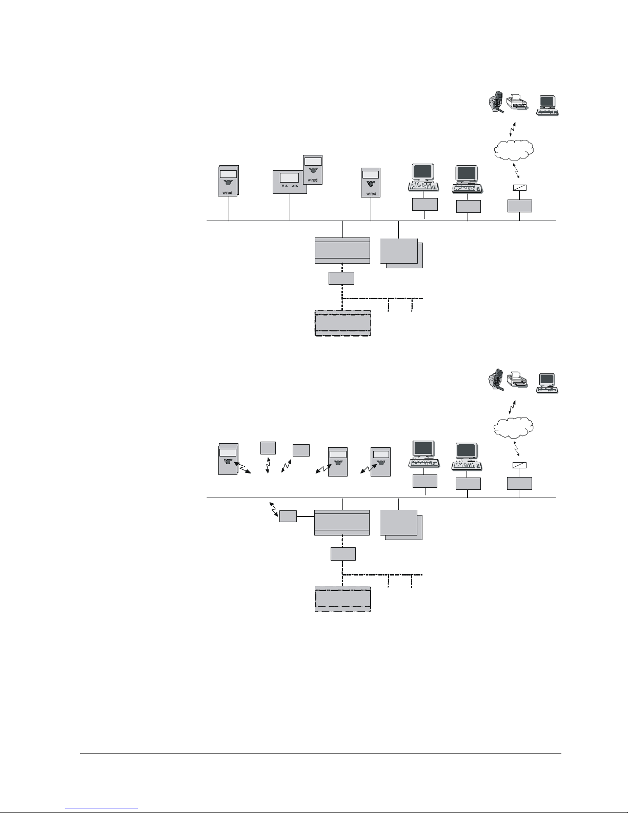
1.3 Product range summary
1.3.1 Topology
Remote
Servi ce tool
Mobile, SMS, Pager , Fax ,
WEB
Tel e f on
Networ k
Tel e f on
SMS
OCI 611
OCI7. ..
ACS700
BSB : Boiler S ystem Bus
Service Unit
(RU)
HMI
HMI
(RU)
Basic Uni t
LMS...
Extens ion
mod. AVS75…
(max. 3)
BSB- W
LPB : Local Process Bus
Basic Unit
LMS... / RVS...
LPB
Servi ce tool
OCI4 30
ACS420
7471z01e/1210
OCI345. ..
Room Unit
Figure 1: Product range summary – wired
Remote
Service tool
Mobile , SMS, Pager , Fax,
WEB
Tel ef o n
Networ k
Tel e fo n
SMS
OCI6 11OCI700
RF
Modul
ACS700
BSB : Boiler System Bus
Room Unit
RF
Repeater
RF
Tou ts id e
BSB-RF
Service Unit
(RU)
HMI
(RU)
Wireless
Wireless
Wireless
Basic Unit
LMS...
Extension
mod. AVS75...
(max. 3)
BSB -W
LPB : Local Process Bus
Basic Unit
LMS.../ RVS...
LPB
Service tool
OCI430
ACS420
7471z02e/1210
OCI345...
Figure 2: Product range summary – wireless
Wired
Wireless
16/617
Building Technologies Division User Manual LMS14... CC1U7471en
1 Summary 28.01.2015
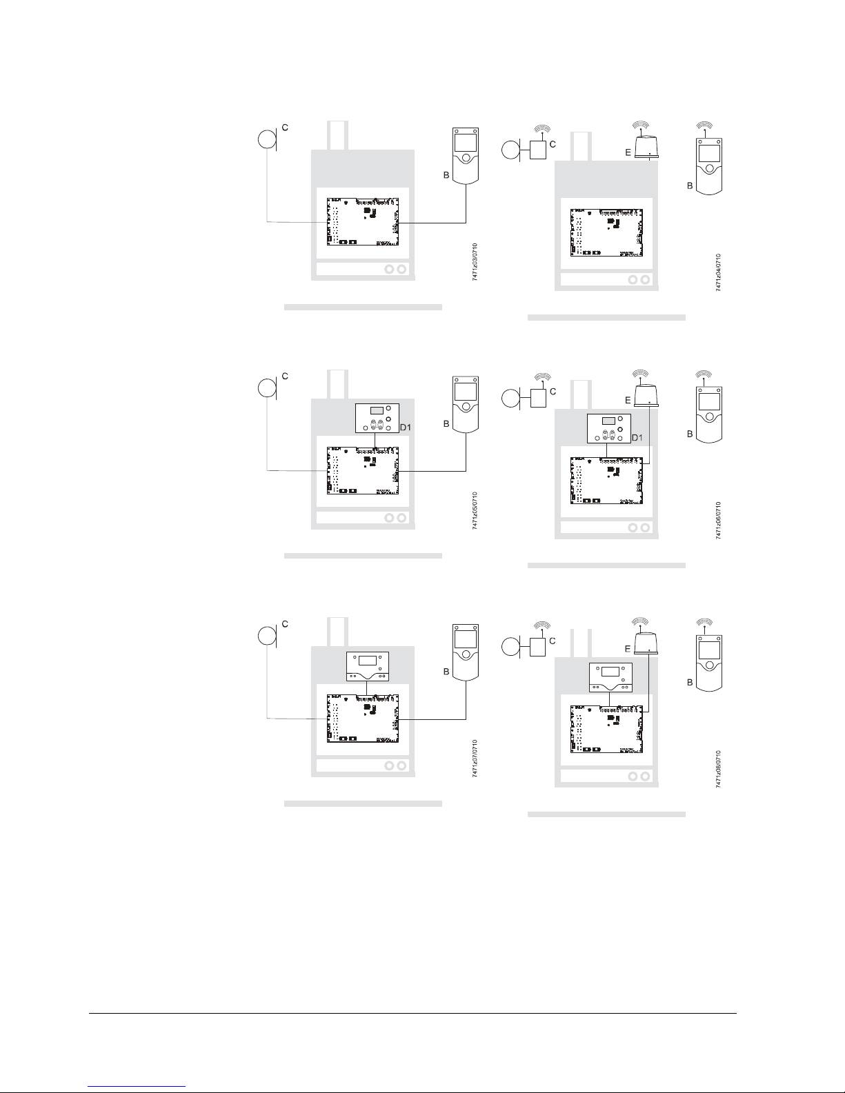
1.3.2 Operating options
Wired Wireless
A
T
A
T
Wired Wireless
A
T
Reset
+
A
T
Reset
+
Wired Wireless
A
T
D
A
T
D
Key
A Basic unit LMS14...
B Room unit QAA55.../QAA75.../QAA78...
C Outside sensor AVS13...
D Operator unit AVS37.294... (Clear-text)
D1 Operator unit AVS37.390... (Basic)
E RF module AVS71...
Operation via room unit
Operation via operator unit
Basic (optionally with
additional room unit)
Operation via operator unit
Clear-text (optionally with
additional room unit)

17/617
Building Technologies Division User Manual LMS14... CC1U7471en
2 Safety notes 28.01.2015
2 Safety notes
2.1 Notes on product liability
The LMS14… may only be used in building services plant and only in compliance
with the applications covered by this document
When employing the products, all requirements specified in chapters Handling and
Technical data must be satisfied
Local safety regulations (installation, etc.) must be complied with
The units must not be opened. If not observed, warranty by Siemens becomes void
Danger!
Do not open, interfere with or modify the units!
All activities (mounting, installation, service work, etc.) must be performed by
qualified personnel
Before performing any work in the connection area of the LMS14…, disconnect the
unit from mains supply (all-polar disconnection). Ensure that the plant cannot be
inadvertently switched on again and that it is indeed dead. If not disconnected,
there is a risk of electric shock
Ensure protection against electric shock by providing adequate protection for the
unit’s terminals
After any kind of activity (mounting, installation, service work, etc.), check to ensure
that wiring is in an orderly state, that all safety functions are performed correctly
and that the parameter settings are correct
Fall or shock can adversely affect the safety functions. Such units must not be put
into operation, even if they do not exhibit any damage
AC 230 V terminals that are not used must be protected by dummy plugs fitted by
the burner manufacturer
Never connect or disconnect the stepper motors (WX1 connected to X16 or
X16a) when live. If not observed, the built-in driver stage can be damaged
Siemens will not assume liability for damage resulting from unauthorized
interference!
If fuses inside the LMS15… are blown, the unit must be returned to Siemens. The
mains fuse (FB01/FB02) may be replaced once
. Since overcurrents can damage
relays, a plant safety check must be made.
Electromagnetic emissions must be checked on an application-specific basis!
The choice of applications and scope of functions covered by this User Manual
shall serve as a guideline. The correct operation of the plant must be checked
and proven by function tests made on the heating appliance and the relevant
plant!
Danger!
At the OEM’s request, the quick connector for the mechanical STB (SLT = safety limit
thermostat) on the printed circuit board can be bridged ex factory. In that case, the
mechanical SLT would be deactivated. When using a mechanical SLT, the resistor
must always be removed. LMS14... with different type numbers must never be mixed
up.

18/617
Building Technologies Division User Manual LMS14... CC1U7471en
2 Safety notes 28.01.2015
2.1.1 Use of high-efficiency pumps
When using high-efficiency pumps or pumps with integrated electronics, the
resulting switch-on currents can adversely affect the relays’ service life. For this
reason, use of these types of pump is permitted only if authorized in writing by
Siemens.
2.1.2 High-voltage test
Caution!
When making 100% inspections to DIN EN 60335-1, Addendum A, only AC
voltage may be applied. If tests are conducted with DC voltage, the LMS14...
might be damaged.

19/617
Building Technologies Division User Manual LMS14... CC1U7471en
2 Safety notes 28.01.2015
2.2 Environmental compatibility
The units contain electrical and electronic components and must not be disposed of
together with domestic waste.
Local and currently valid legislation must be complied with!
2.3 Lifecycle
The LMS14… have a designed lifetime* of 250,000 burner startup cycles which, under
normal operating conditions in Heating mode, correspond to approx. 10 years of usage
(starting from the production date indicated on the type field).
This lifetime is based on the endurance tests in the standard EN 298.
A summary of the conditions has been published by the European Control
Manufacturers Association (Afecor) (www.afecor.org
).
The designed lifetime is based on usage of the LMS14… as specified in the
manufacturer’s Data Sheet and User Manual. After reaching the designed lifetime in
terms of the number of burner startup cycles, or the respective time of usage, the
LMS14… are to be replaced by authorized personnel.
* The designed lifetime is not identical with the warranty time specified in the Terms of
Delivery
2.4 Standards and certificates
Conformity to EEC directives
- Electromagnetic compatibility EMC (immunity)
- Directive for gas-fired appliances
- Low-voltage directive
2004/108/EC
2009/142/EC
2006/95/EC
ISO 9001:2008
ISO 14001:2004
OHSAS 18001:2007
Identification code to EN 298: 2003 chapter 4: F M C L B N
Disposal
20/617
Building Technologies Division User Manual LMS14... CC1U7471en
2 Safety notes 28.01.2015
2.5 Typographical conventions
2.5.1 Safety notes
This User Manual contains instructions which must be observed to ensure your
personal safety and to prevent damage to equipment and property. The instructions
and notes are highlighted by warning triangles, arrows or information symbols and are
presented as follows, depending on the hazard level:
Danger
means that death, severe personal injury or substantial
property damage will occur if adequate precautionary
measures are not taken.
Warning
means that death, severe personal injury or substantial
property damage can occur if adequate precautionary
measures are not taken.
Caution
means that minor personal injury or property damage
can occur if adequate precautionary measures are not
taken.
Note draws your attention to important information on the
product, on product handling, or to a special part of the
documentation.
Reference refers to further information given in other pieces of
documentation or in chapters of this document.
Only qualified personnel are allowed to install and operate the equipment. Qualified
personnel in the context of the safety-related notes contained in this document are
persons who are authorized to commission, ground and tag devices, systems and
electrical circuits in compliance with established safety practices and standards.
Note the following:
The LMS14… may only be used on applications covered by the technical description.
The use of unsuitable or incorrectly installed accessories can lead to personal injury or
damage to property.
When using the unit in connection with third-party products or components, following
must be noted:
- The technical data of the LMS14… must be observed; in addition to static data,
consideration must be given to dynamic data, such as switch-on and switch-off
currents, surge currents, etc.
- EMC-specific properties or retroactive effects can adversely affect the unit’s life and
reliability and must be checked by the customer
- The OEM as the system integrator must ensure compliance with the relevant
regulations and make certain the correct fuses are used
- Siemens assumes no responsibility for the system
The products can only function correctly and safely if shipped, stored, set up and
installed correctly, and operated and maintained as specified.
Qualified personnel
Correct use

21/617
Building Technologies Division User Manual LMS14... CC1U7471en
3 Mounting and installation 28.01.2015
3 Mounting and installation
3.1 Safety regulations
Prior to installation, disconnect power
The low-voltage and mains voltage terminals are arranged on different sides of the
unit
Warning!
Never run ionization probe cable and mains cables in the same trunk.
This unit does not provide any separate line protection for supply cables
running to external loads (field supply)!
The cable insulation must always be appropriate for the rated voltage
concerned.
If supply voltages (including a 24 V extra-low voltage) are fed to external loads,
the cross-sectional areas used must always be suitable for the rated value of
the upstream overcurrent protective device.
Always observe the relevant local regulations in this regard.
Warning!
When making the wiring, the AC 230 V section must be strictly segregated
from the extra low-voltage section, thus ensuring protection against
electric shock and electromagnetic interference
In connection with the (safety) limit thermostat, observe the safety-related
notes given in chapter Electronic safety limit thermostat (SLT)
Make certain that spliced individual wires cannot touch neighboring
terminals. Fit suitable ferrules
Always run the high-voltage ignition cables separate from the unit and
other cables while observing the greatest possible distances
Danger!
Compliance with DIN EN 60335 and DIN EN 60730-2-5 must be ensured
The electrical wiring inside the boiler must conform to national and local
regulations
Degree of protection IP40 as per DIN EN 60529 for burner controls must be
ensured by the burner or boiler manufacturer through correct installation
of the LMS14...
3.1.1 Electrical connection of ionization probe
It is important to achieve practically disturbance- and loss-free signal transmission:
Never run the ionization probe cable together with other cables
- Line capacitance reduces the magnitude of the flame signal
- Use a separate cable
Observe the permissible length of the ionization probe cable (refer to chapter
Technical data in the relevant pieces of documentation)
Locate ignition electrode and ionization probe such that the ignition spark cannot
arc over to the ionization probe (risk of electric shock)
Locate the ionization probe and its connections such that adequate protection
against direct or indirect contact with active parts is ensured in every unfavorable
position allowed under correct usage conditions. If not observed, there is a risk of
electric shock
Electrical installation

22/617
Building Technologies Division User Manual LMS14... CC1U7471en
3 Mounting and installation 28.01.2015
3.1.2 Electrical connection on 2-phase systems
When operating the LMS14 on 2-phase systems, the following points must be observed:
You must adhere to the mains voltage and mains frequency values specified in the
technical data
The components you connect to the LMS14 (gas valve, igniter, etc.) must be
suitable for 2-phase operation
Make sure to connect the phases correctly.
There is a phase angle of 120° between the phases. Therefore, the sequence in
which the phases are connected does make a difference.
Connecting them incorrectly can result in an excessively low ionization current and
lead to "loss of flame" faults.
To ensure they are connected correctly, we recommend following the procedure
described below:
1. The characteristic ionization current for a particular type of boiler must be
determined by the OEM in 1-phase operation and documented in the Service
Manual.
This value can be read by referring to the Ionization current (8329) line in the
Diagnostics heat source menu.
2. When commissioning a boiler on a 1-phase system, it is essential to check the
Ionization current (8329).
If it is the same as or higher than the value in the Service Manual, the phases
have been connected correctly.
If the Ionization current (8329) is lower than the value in the Service Manual,
the phases have been connected incorrectly and must be swapped round.

23/617
Building Technologies Division User Manual LMS14... CC1U7471en
3 Mounting and installation 28.01.2015
3.2 Boiler management unit LMS14…
When mounting the PCB on a metal plate, the clearance between the lower edge
of the PCB and the metal plate must be a minimum of 12 mm (as per DIN EN
60335 minimum 8 mm air and creepage path to the end of the wires or the
solder fillets).
- Spacers must be made of electrically non-conductive material!
- When using metal screws for fixing, the head diameter must be 7.5 mm!
- If 2 metal screws are screwed into a spacer from both sides, an air path of 8 mm
must be observed or solid insulation of 2 mm must be provided (as per
DIN EN 60335)!
Caution!
Mounting (general information)
Currently valid national safety regulations must be complied with!
Inside the boiler, the unit must be fitted in a housing ensuring degree of
protection IP40 as a minimum requirement
Depending on the location and environmental conditions, higher degrees of
protection may be required
When mounted, the maximum permissible ambient temperature must never be
exceeded
Condensation water must not drip on the LMS14… or enter the unit, neither in
operation nor when service work is carried out
Ignition equipment
Note!
In terms of switching performance, any type of external ignition module used must be
approved by Siemens!
Electric ignition sparks generate high-frequency energy which can adversely affects
radio and television reception. The high-voltage cable running to the ignition electrode
acts as a transmit antenna. For this reason, application-specific tests must be made to
confirm that adequate distances are observed. High-frequency energy is also of
capacitive and inductive nature, that is, not wire-bound. This must be taken into
consideration when laying the cables.
The ignition cable used must satisfy the technical requirements of the ignition
module and should be run to the ignition electrode as directly as possible, with
no loops in between.
It must never be laid parallel or very close to other electrical cables.

24/617
Building Technologies Division User Manual LMS14... CC1U7471en
3 Mounting and installation 28.01.2015
Connections and wiring
When making the wiring, ensure that the protective extra low-voltage side is
strictly separated from other sections, thus providing protection against electric
shock and making certain that EMC will not be adversely affected! The
connectors’ predefined coding must be observed! Make the connections only
when the components are disconnected from power! AC 230 V terminals that are
not used must be covered by dummy plugs to ensure protection against electric
shock! A multipole isolator is required to disconnect the unit from mains supply.
For wiring the bus users, cables specified by Siemens are mandatory!
External signal sources (air pressure switch, room thermostat, DHW flow switch, etc.)
should have gold-plated silver contacts.
Both ionization probe and ignition electrode must be protected against electric shock.
Since the line to the ionization probe must be well insulated against ground, that line
together with the ionization probe must be protected against condensation and very
damp surroundings.
Warning!
Connector X17 for the burner ground must be connected as directly as
possible to protective earth (PE) of the mains cable and to X1 or X1a, pin 2, at
the mains input of the LMS14...
The burner’s housing must also be connected to the protective earth of the
mains cable.
The safety regulations for protective earth wiring must be complied with in all
cases.
Neutral point is the protective earth terminal of the mains cable.
The way protective earth is wired has a considerable impact on whether the
emission limits as per DIN EN 60335 are adhered to and on the unit’s EMC
performance inside the boiler.
Tests made by the customer
If the boiler or burner manufacturer wants to make additional insulation and high-
voltage tests, prior approval by Siemens is required!
As regards Directive 2004/108/EC (EMC): Once this component has been installed
in the equipment, evidence and explanatory information must be provided to
demonstrate that the relevant requirements have been met.
Engineering
The flow sensor (B2) and the return sensor (B7) are safety-related
components!
They must meet the requirements of DIN EN 14459:2007 Annex K while also
adhering to EN 15502-1:2012 Section 5.7.8.3.2 b).
Air circulation around the LMS14… must be ensured, enabling the unit to dissipate
the heat produced by its controller
The unit has been designed for use inside equipment of safety class I and must be
installed accordingly
Power may be switched on only when the unit is completely mounted. Otherwise,
there is a risk of electric shock at the terminals and through the cooling slots
The unit must not be exposed to drip water
Mains cables must be run completely separate from low-voltage cables (sensors),
observing a minimum distance of 100 mm
Mounting location
The LMS14… has been designed for mounting inside the burner or inside a control
panel. Protection against electric shock must be ensured!
25/617
Building Technologies Division User Manual LMS14... CC1U7471en
3 Mounting and installation 28.01.2015
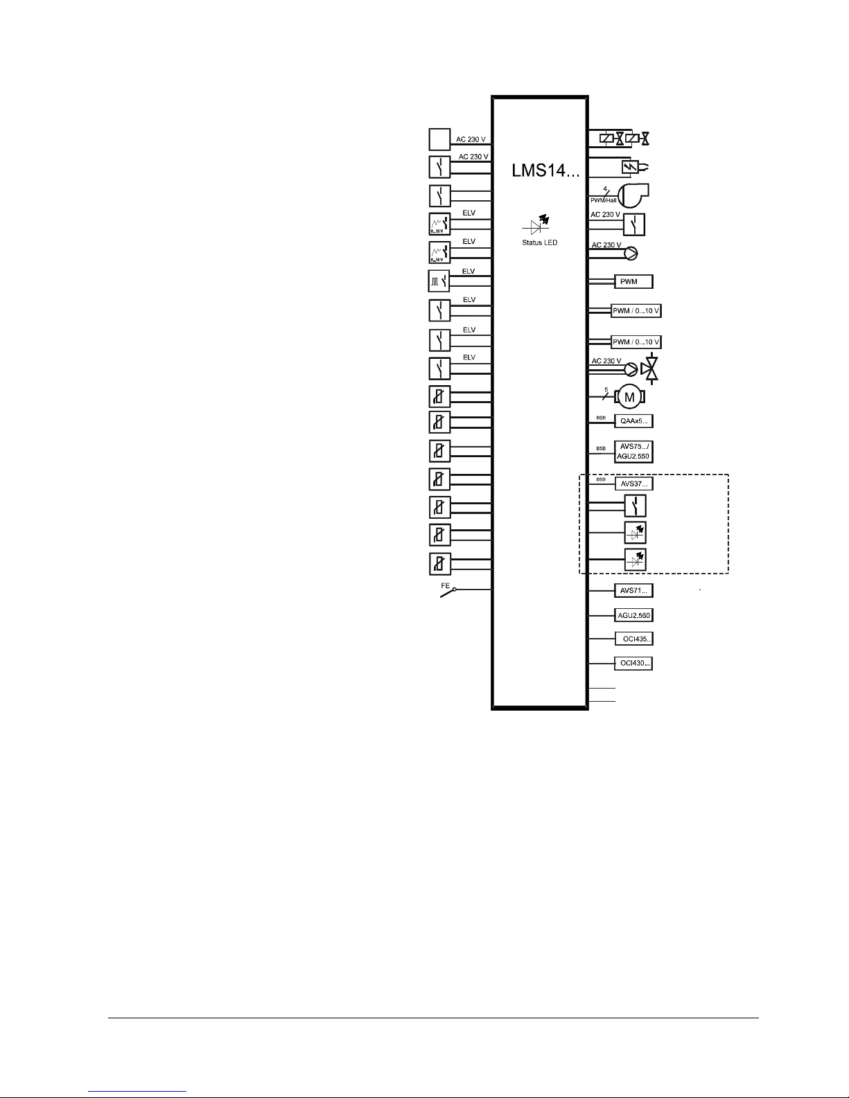
3.3 Basic diagram LMS14…
7471a44e/1214
Mains voltage
Lockout
(Safety temperature limiter,
Temperature li miter)
Lockout r eset butt on
Programmable analog /
digital input
Programmable analog /
digital input
Programmable frequenzy /
digital input
Programmable digital
input
Gas pressure switch or programmable
digital input
Air pressure switch or
progr amm able d igital
input
Boiler flow sensor
DHW sensor 1
Outside sensor
Multifunction sensor
Multifunction sensor
Multifunction sensor
Boiler return sensor /
multifunction sensor
Flame supervision
(continuous)
L1, N, PE / L1, L2, PE
(L1 / N )
replaceable
(S)TB / TB
Reset
H1
H3
H4
H5
H6
H7
B2
B3 / B38
B9
BX1
BX2
Bx3
Return flow B7 / BX4
Threshold programmable /
Dual or single electrode operation
Fuel valve
AC 230 V
Ignition module
AC 230 V
Variable Geschwindigkeit
PWM fan
AC 230 V
Multifunction
outpur
Heating circuit pump
Analog output
Analog output
Analog output
DHW pump 1
or diverting valve
Unipolar / bipolar
stepper motor
(diverting valve)
Room unit S / 1 / 2 / 3
Extension module 1 / 2 / 3
Operator unit
Reset
LED interference
LED flame
Radio module
Parameter stick
LPB module
PC tool
Line A UX1 (fuse )
Line A UX2 (fuse )
QX1
QX2
P1
UX2
UX3
QX3
QX4
Figure 3: Basic diagram
The diagram shows the full scope of functions of the LMS14… system.
The actual functions are to be determined based on the respective
execution/configuration.
26/617
Building Technologies Division User Manual LMS14... CC1U7471en
3 Mounting and installation 28.01.2015
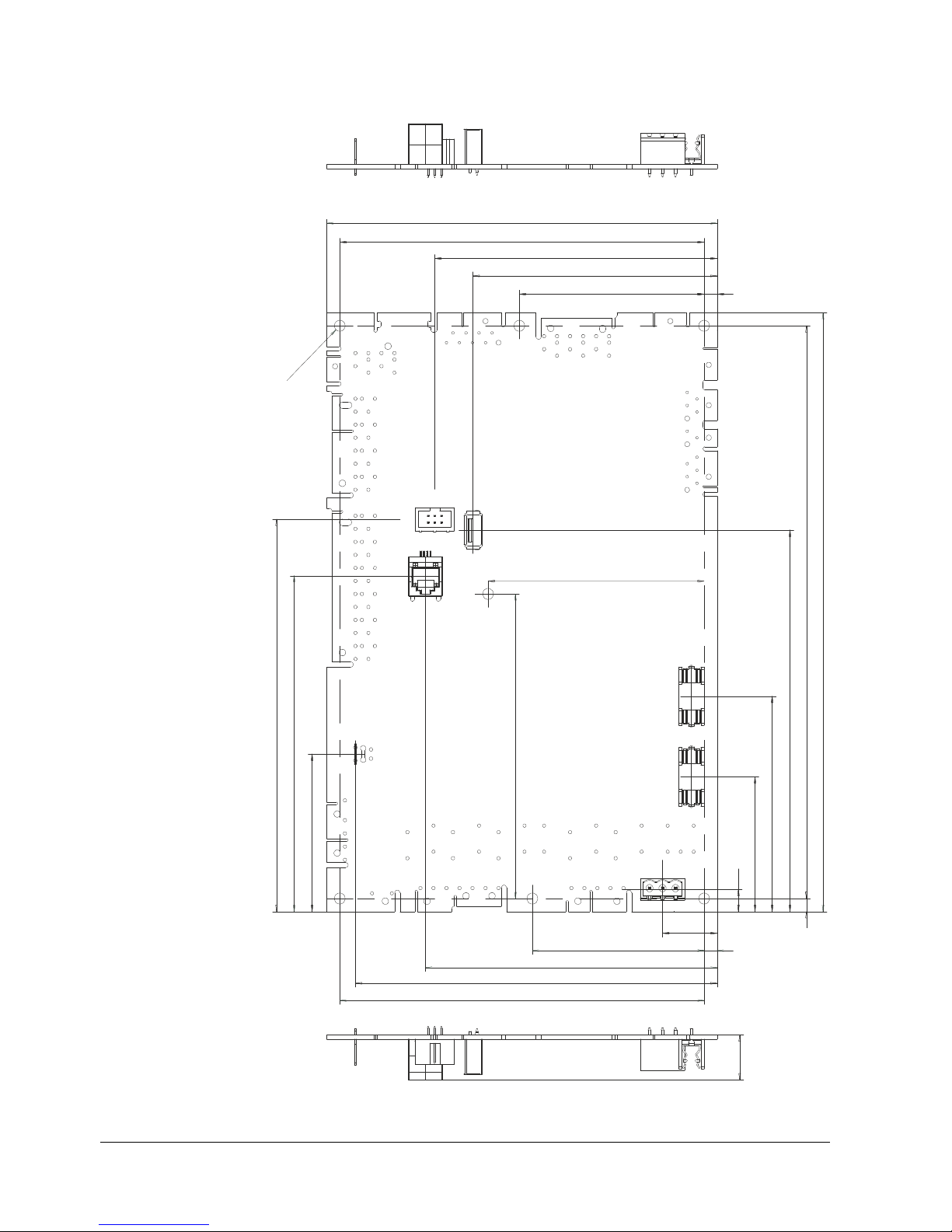
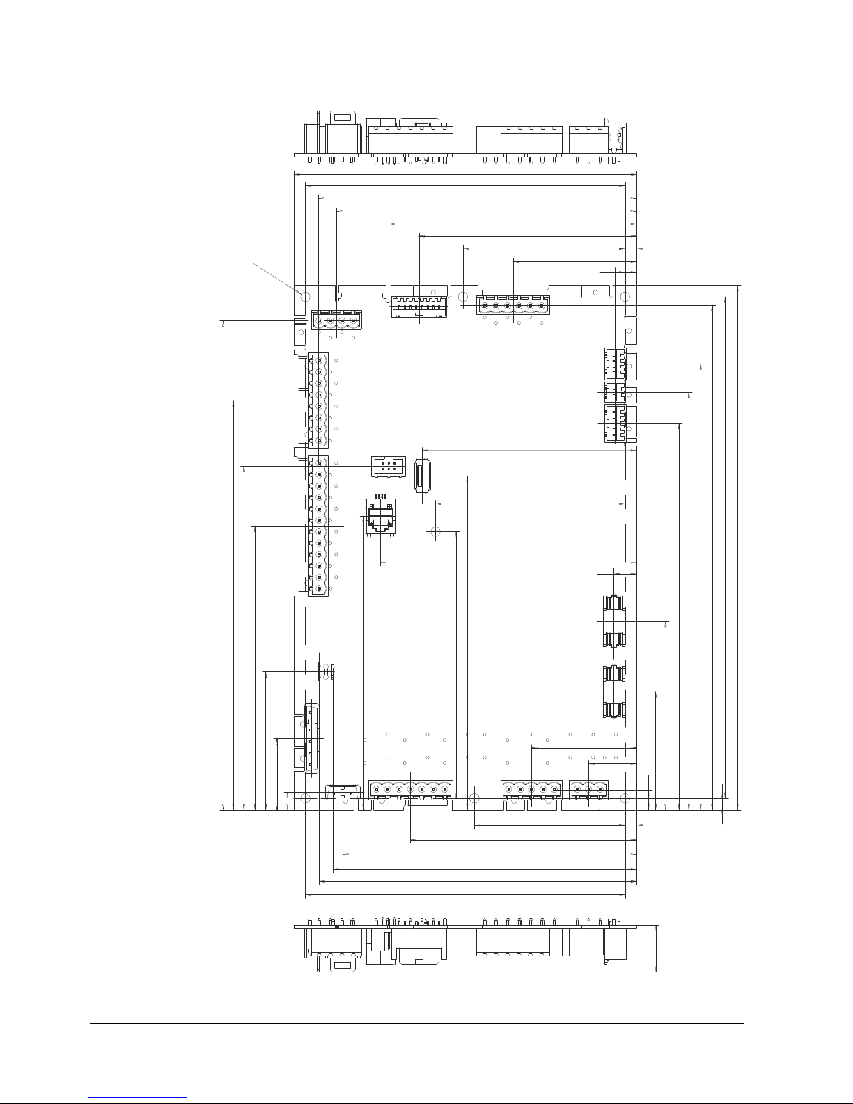
3.4 Basic unit LMS14… complete (Basic)
Dimensions in mm
150
140
108,5
93,8
71
5
Ø
4
,
2
(
7
x
)
83
117
150,7
129
60,5
82,7
146,5
220
230
8,6
51,8
5
21
5
66
112,1
139
140
17,2
7471m27/0514
Figure 4: Dimensions of basic unit complete (Basic)
27/617
Building Technologies Division User Manual LMS14... CC1U7471en
3 Mounting and installation 28.01.2015
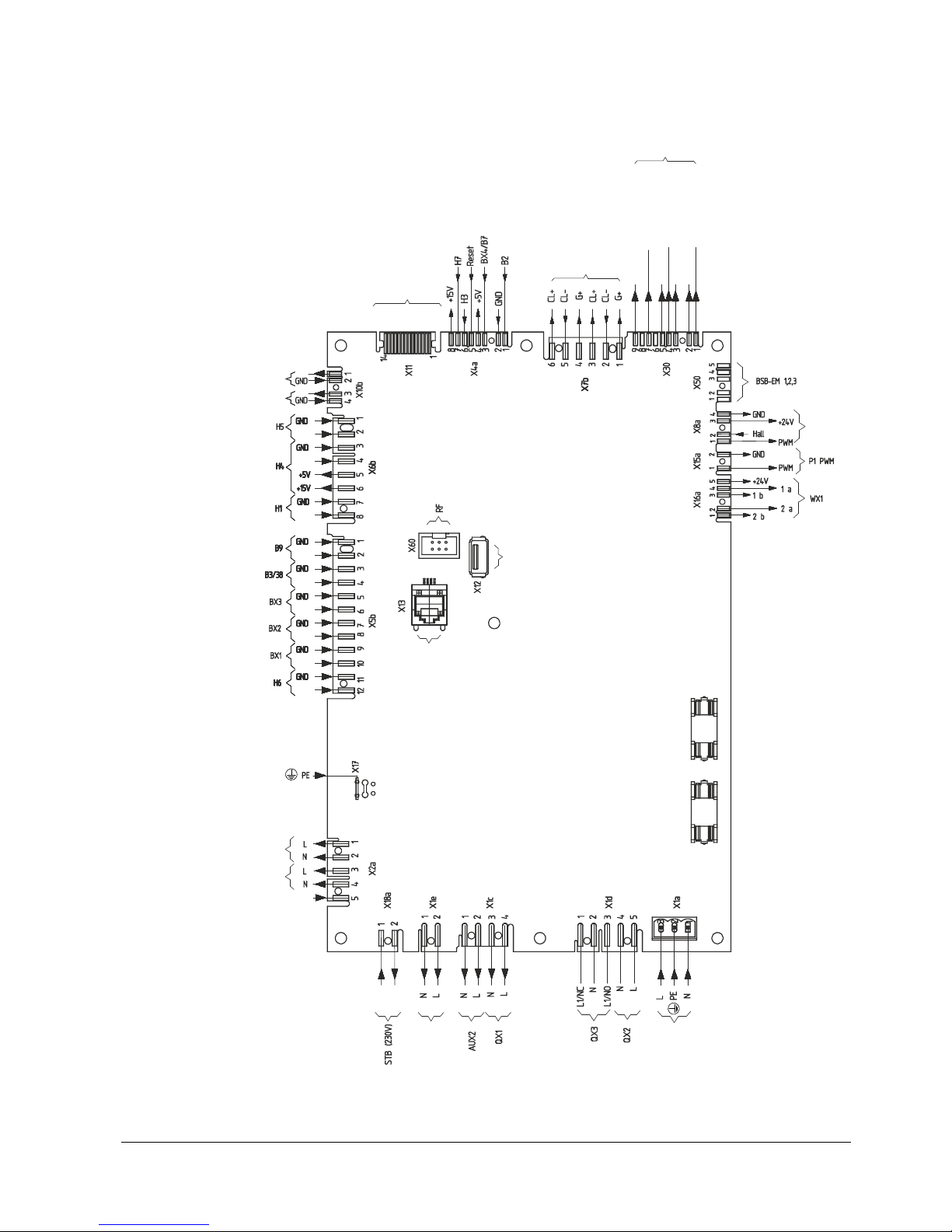
3.4.1 Terminals of LMS14… complete (Basic)
LED flame
LED interference
Reset
Identification port
+12 V
CL+
GND
BSB operator unit
Fan PWM
AUX1 / fan
Mains supply
Ionization
Ignition module
Fuel valve
OCI430
AGU2.56...
BSB bus room unit
OCI345...
7471a4 1e/1214
UX2
UX3
Figure 5: Terminals of LMS14… complete
28/617
Building Technologies Division User Manual LMS14... CC1U7471en
3 Mounting and installation 28.01.2015
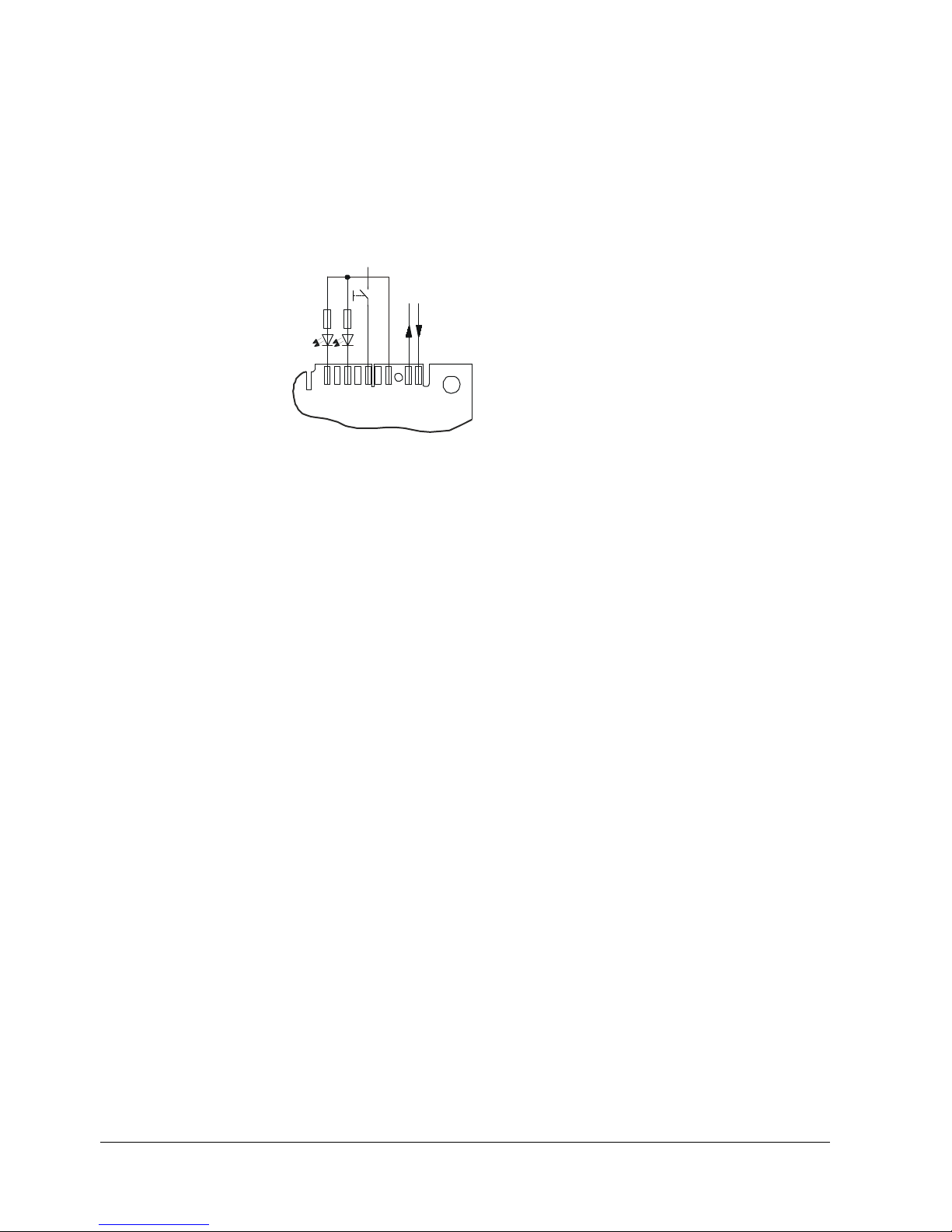
3.4.2 Assignment of terminal X30
7471m22e/1214
LED flame
LED interference
CL+
GND/CL-
Rv = external
Status LEDs
Uex t 12 V
987654321
X30
Rv
Rv
GND
ET
Figure 6: Assignment of terminal X30
29/617
Building Technologies Division User Manual LMS14... CC1U7471en
3 Mounting and installation 28.01.2015
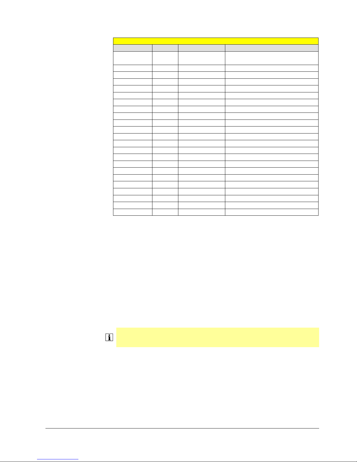
3.4.3 List of terminals of LMS14… complete (Basic)
LMS14... standard (Basic)
Terminal Mating connector
marking Number
of pins
Supplier Type/coding
X1a 3 Wieland 25.320.3353.0 green
X1c 4 Lumberg 3636 04K02
X1d 5 Lumberg 3636 05K02
X1e 2 Lumberg 3636 02K10
X2a 5 Lumberg 3636 05K22
X4a 8 Lumberg 3515 08K20
X5b 12 Lumberg 3636 12K01
X6b 8 Lumberg 3636 08K10
X7b 6 Lumberg 3636 06K09
X8a 4 Lumberg 3515 04K06
X10b 4 Lumberg
3515 04K26
X11 14 Lumberg 302299 14 uncoded
X12 4 Molex 48037-2200 uncoded
X13 6/4 Uncoded
X15a 2 Lumberg 3516 02K05
X16a 5 Lumberg 3515 05K25
X17 1 Uncoded
X18a 2 Lumberg 3636 02K05
X30 9 Lumberg 3515 09K15
X50 5 Lumberg 3515 05K23
X60 2x3 Uncoded
Key to LMS14… complete (Basic)
AUX... Auxiliary output
B2 Boiler sensor
B3 DHW sensor
B7 Boiler return sensor
B9 Outside sensor
B38 DHW outlet sensor
BX... Sensor input
H... Function input
P1 PWM output
QX... Relay output
STB Safety limit thermostat (SLT)
UX... PWM output / 10 output
WX1 Stepper motor output
Note!
The connector designations only specify coding and type. When ordering, also
consider the requirements placed on the material (e.g. filament test) and design.
30/617
Building Technologies Division User Manual LMS14... CC1U7471en
3 Mounting and installation 28.01.2015
3.5 Basic unit LMS14... complete (Medium)
Dimensions in mm
150
140
139,4
131,5
108,5
95,2
71
54
9,33
5
Ø
4
,
2
(
7
x
)
93,8
83
112,1
9,9
214,5
179,5
169,5
183,2
195,65
221,4
220
230
150,7
124,5
60,5
31,3
7,8
129
117
146,5
46
21
8,6
51,8
82,7
5
66
5
99
128,7
133
139
140
20,4
7471m26/0514
Figure 7: Dimensions of basic unit complete (Medium)
 Loading...