

Siemens LME7 Series, LME75, LME71, LME73 Technical Instructions
SCC Inc.
Technical Instructions LME-1000
June 11, 2019
www.scccombustion.com
L M E 7…
Burner Controls
Combustion Controls

IntentionallyLeftBlank

LME Series Technical Instructions
Document No. LME-1000
Table of Contents
Section 1: Overview
Introduction ........................................................................................................................... 1
LME7 System Builder ............................................................................................................. 2
Mounting ............................................................................................................................. 10
Important Safety Notes ........................................................................................................ 12
Approvals ............................................................................................................................. 13
Section 2: LME71 Wiring, Parameters, and Phase Diagrams
LME71 Wiring Diagrams ......................................................................................................... 1
LME71 Parameter List ............................................................................................................ 4
LME71 Phase Diagrams ........................................................................................................ 11
Section 3: LME73 Wiring, Parameters, and Phase Diagrams
LME73 Wiring Diagrams ......................................................................................................... 1
LME73 Parameter List ............................................................................................................ 4
LME73 Phase Diagrams .......................................................................................................... 9
Section 4: LME75 Wiring, Parameters, and Phase Diagrams
LME75 Wiring Diagrams ......................................................................................................... 1
LME75 Parameter List ............................................................................................................ 3
LME75 Phase Diagrams .......................................................................................................... 8
Section 5: Commissioning
Commissioning a New LME7 Burner Control .......................................................................... 1
Parameter Backups / Restores ............................................................................................... 2
Displaying the Flame Signal from the LME7 Burner Control.................................................... 3
Displaying the Actuator Position / PWM Blower Speed from the LME7 Burner Control .......... 4
Manually Adjusting the Actuator Position / PWM Blower Speed from the LME7 Burner
Control ............................................................................................................................. 4
AZL23 Display Unit Icons ........................................................................................................ 4
SCC Inc. Page 1 Table of Contents

Technical Instructions LME Series
Document No. LME-1000
Section 6: PWM Blowers
Introduction ........................................................................................................................... 1
PWM Blower Fundamentals ................................................................................................... 1
Centrifugal Blower Fundamentals .......................................................................................... 2
Blower Speed Monitoring ...................................................................................................... 3
Commissioning the LME7 when Using a PWM Blower............................................................ 5
Adjusting P0, P1, and P2 via the LME7 Built-in Display ........................................................... 7
Adjusting P0, P1, and P2 via the AZL23 Display Unit ............................................................... 8
Additional Tips for Burners with PWM Blowers ...................................................................... 9
Section 7: Troubleshooting
Troubleshooting Introduction ................................................................................................ 1
Complete Fault Code List ....................................................................................................... 3
Other Common Faults ............................................................................................................ 7
Section 8: Modbus
Introduction ........................................................................................................................... 1
Physical Connections.............................................................................................................. 1
Status LED .............................................................................................................................. 2
Tx/Rx LED ............................................................................................................................... 2
Modbus RTU Connection Details ............................................................................................ 3
BACnet MS/TP Connection Details ......................................................................................... 4
Using the OCI417 Configuration Utility ................................................................................... 5
Updating the OCI417.10 Firmware ......................................................................................... 7
Modbus Mapping ................................................................................................................... 8
BACnet Mapping .................................................................................................................. 11
Unused Inputs ...................................................................................................................... 13
Table of Contents Page 2 SCC Inc.

LME Series Technical Instructions
Document No. LME-1000
Section 9: ACS410
ACS410 Software Introduction ............................................................................................... 1
Software Installation .............................................................................................................. 2
Connecting to a PC ................................................................................................................. 3
Saving a Parameter Set to a PC .............................................................................................. 4
Uploading a Parameter Set to an LME7 .................................................................................. 5
Creating an LME7 Startup Report ........................................................................................... 6
Synchronizing the LME7 and PME Parameters ....................................................................... 7
Saving and Viewing Trends ..................................................................................................... 8
Viewing the Status Screen .................................................................................................... 10
Appendix A: Application Guide
Honeywell Modutrol IV Motor with the LME75 ...................................................................... 3
Two Flame Detectors ........................................................................................................... 13
SCC Inc. Page 3 Table of Contents

Technical Instructions LME Series
Document No. LME-1000
Intentionally Left Blank
Table of Contents Page 4 SCC Inc.

Section 1
Overview
Section 2
LME71 Wiring, Parameters,
and Phase Diagrams
Section 3
LME73 Wiring, Parameters,
Section 4
LME75 Wiring, Parameters,
Section 5
Commissioning
Section 6
PWM Blowers
Section 7
Troublesho
oting
Section 8
Modbus
Section 9
ACS410
Appendix A
Application Guide
and Phase Diagrams
and Phase Diagrams

Section 1
Overview
Section 2
LME71 Wiring, Parameters,
and Phase Diagrams
Section 3
LME73 Wiring, Parameters,
Section 4
LME75 Wiring, Parameters,
Section 5
Commissioning
Section 6
PWM Blowers
Section 7
Troubleshooting
Section 8
Modbus
Section 9
ACS410
Appendix A
Application Guide
and Phase Diagrams
and Phase Diagrams
LME Series Technical Instructions
Document No. LME-1000
Introduction
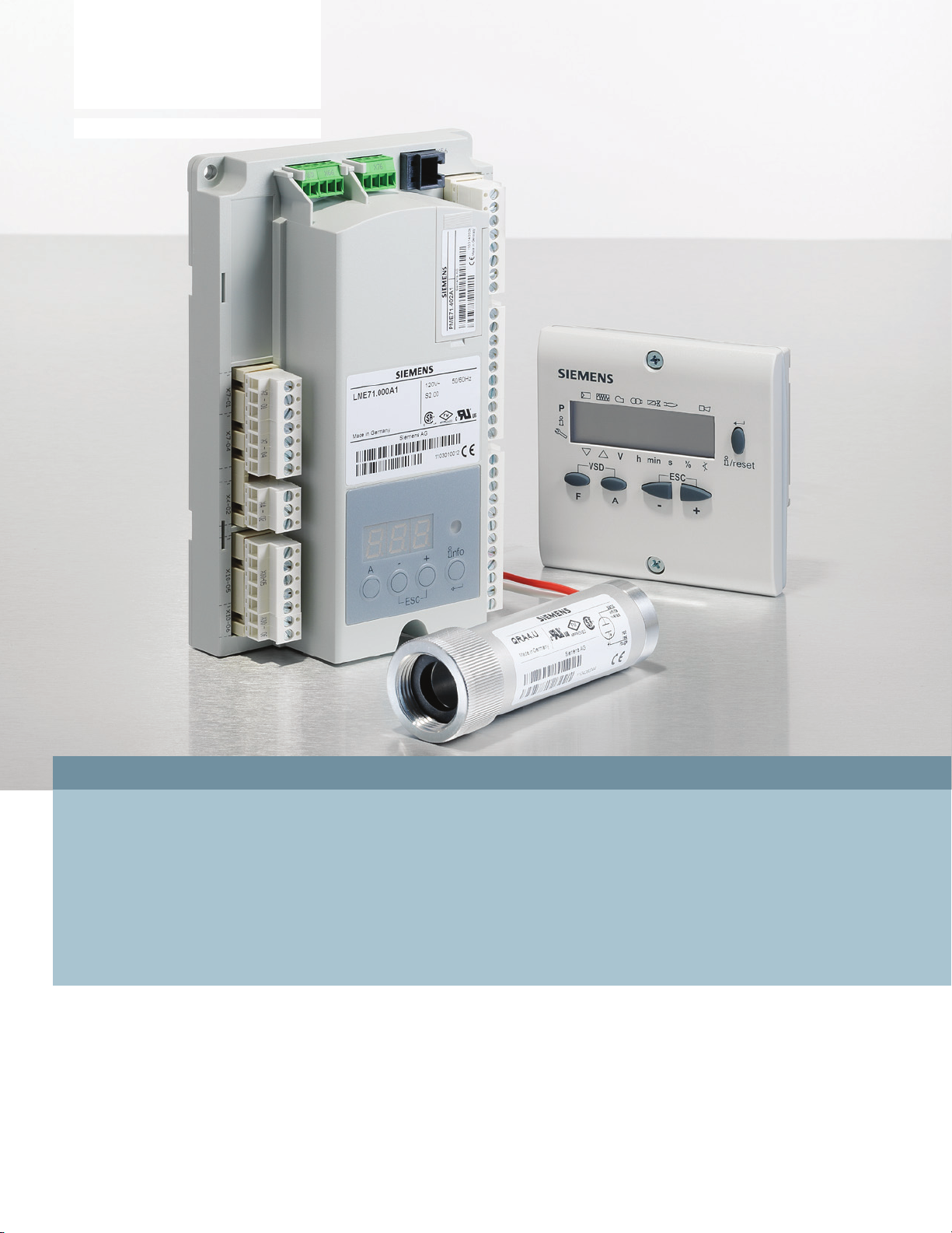
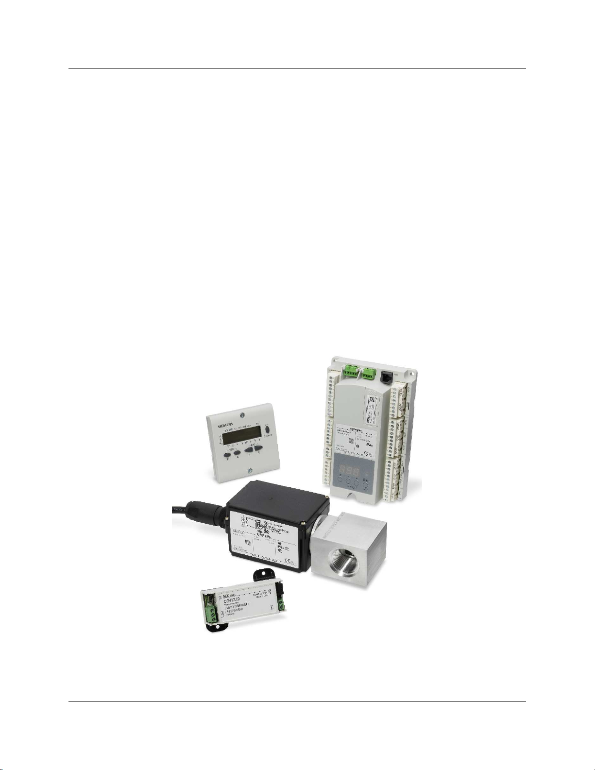
The LME7 burner control is ideally suited for use in industrial thermal process applications. The
LME7 is extremely flexible, and encompasses the following features:
• Accepts standard UV, self-check UV, or self-check IR scanners and/or flame rods
• Integral LED display
• Programmable purge times and safety times
• Programmable actuator positions for purge, ignition, and low fire
• Adjustable time overlap of spark ignition and pilot valve
• Adjustable time overlap of pilot and main gas valves
• Proof-of-closure (POC) switch monitoring
• Modbus RTU or BACnet MS/TP communication
• Optional gas valve proving function
• Password-protected access to OEM parameters
• Integrated actuator control
• Integrated PWM blower control
Figure 1-1: The Main Components of an LME7 System
SCC Inc. Page 1 Section 1

Technical Instructions LME Series
Document No. LME-1000
LME7 System Builder
The LME7 burner control system is comprised of many components. Use the following pages to
choose the components needed for your specific application.
Control Panel Components
Base Unit – Qty (1) Required
Choose one of the following LME7 base unit options. See page 10 for mounting information.
LME71.000A1
self-check scanner capability, 110V
Flame safeguard, with actuator control, without
Flame safeguard, without actuator control, without
LME73.000A1
self-check scanner capability, 110V
Flame safeguard, with actuator control, with self-
LME75.000A1
check scanner capability, 110V
Program Module – Qty (1) Required
Choose one of the following PME7 program modules. The program module contains the
program sequence used to operate the burner.
Base Unit
PME71.111A1
PME71.112A1 • •
PME71.901A1 • • • • • •
PME73.811A1
PME73.812A1 • • •
PME73.840A1 • • • • • •
PME75.811A1
PME75.812A1 • • • •
LME71.000A1
LME73.000A1
LME75.000A1
Controls Actuator
Actuator Control Can Be Disabled
• •
• • • • • •
• • • • • • •
Controls PWM Blower
Flame Rod
Non-Self-Checking UV Scanner
Self-Checking UV or IR Scanner
Valve Proving
Purge
•
• • •
• • •
Independent Ignition Position
Analog Input for Fire Rate
Section 1 Page 2 SCC Inc.
LME Series Technical Instructions
Document No. LME-1000
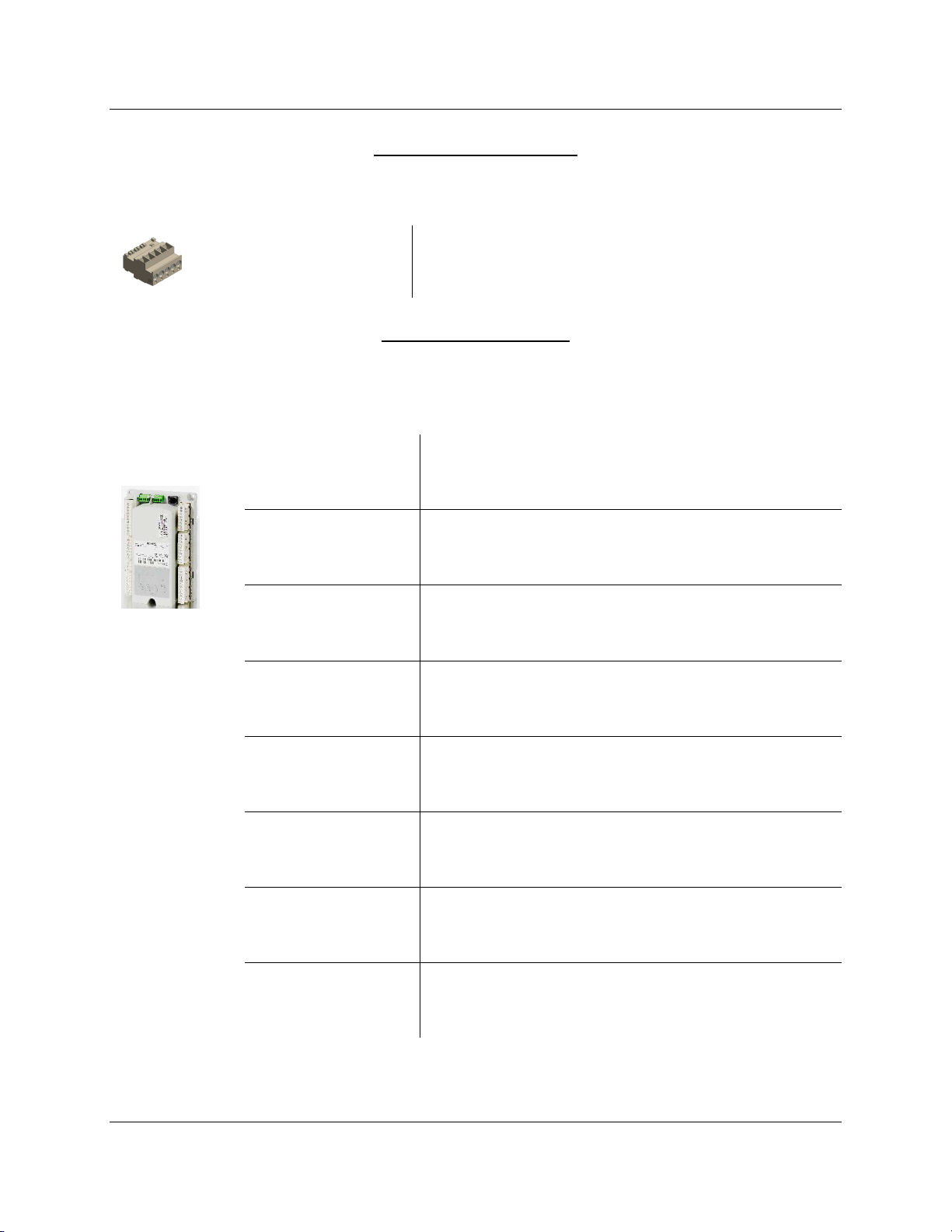
Plug Set – Qty (1) Required
The terminal plug set for the LME7 is sold separately. Each LME7 needs one plug set.
AGG3.710
Plug set containing all terminals for an LME7 system
LME7 Package - Optional
For convenience, the LME7 base unit, PME7 program module, and AGG3.710 plug set can be
ordered as a package that is shipped pre-assembled.
LME71.000A1 with PME71.111A1 program module
LME71.111A1PKG
and AGG3.710 plug set installed
LME71.000A1 with PME71.112A1 program module
LME71.112A1PKG
LME71.901A1PKG
LME73.811A1PKG
and AGG3.710 plug set installed
LME71.000A1 with PME71.901A1 program module
and AGG3.710 plug set installed
LME73.000A1 with PME73.811A1 program module
and AGG3.710 plug set installed
LME73.812A1PKG
LME73.840A1PKG
LME75.811A1PKG
LME75.812A1PKG
LME73.000A1 with PME73.812A1 program module
and AGG3.710 plug set installed
LME73.000A1 with PME73.840A1 program module
and AGG3.710 plug set installed
LME75.000A1 with PME75.811A1 program module
and AGG3.710 plug set installed
LME75.000A1 with PME75.812A1 program module
and AGG3.710 plug set installed
SCC Inc. Page 3 Section 1
Technical Instructions LME Series
Document No. LME-1000
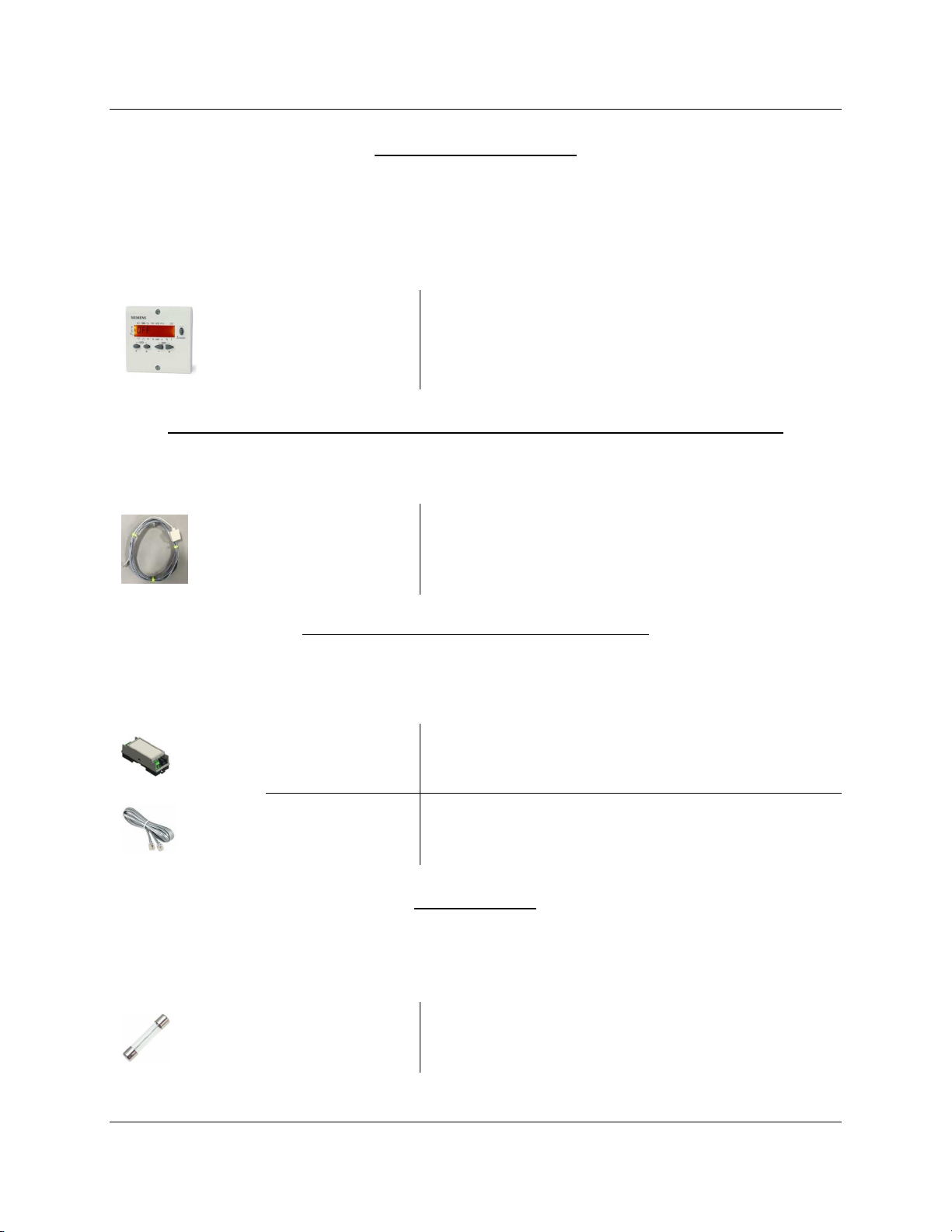
Remote Display – Optional
Each LME7 can be equipped with a remote display that provides additional status information
not shown by the integral LED display on the LME7. Either the remote display or the ACS410
software are required to change parameter settings on the LME7. See page 11 for mounting
information and panel cutout dimensions.
AZL23.00A9
Backlit remote display
Remote Display Cable – Qty (1) Required if Using the AZL23.00A9 Remote Display
This cable is required when using an AZL23 display to connect the AZL23 to the LME7 base unit.
Pre-made 7 foot cable and adapter for connecting
TDCCOMBO
the AZL23 display to the LME7 base unit
Interface Modules and Accessories – Optional
A separate interface module is required for Modbus or BACnet MS/TP communication with the
LME7.
OCI417.10
Modbus and BACnet MS/TP interface module
TDC207
7 foot cable to connect OCI417.10 to LME7 base unit
Fuses - Optional
The LME7… base units do not have a built-in replaceable fuse. It is recommended to install an
external fuse on the incoming power to the LME7.
FUSE6.3A-SLOW
5-pack of 6.3A, 250V, 5x20mm, slow blow fuses
Section 1 Page 4 SCC Inc.
LME Series Technical Instructions
Document No. LME-1000
Actuators and Accessories
Actuator – Qty (1) Optional with LME73 and LME75 Burner Controls
SQM4… and SQM5… series actuators are available for use with the LME73 and LME75 burner
controls. For more information on SQM4… actuators, refer to Document No. N7817. For more
information on SQM5… actuators, refer to Document No. 155-517P25.
SQM4…
adjustable switches, zero and span adjustment
90-400 in-lb torque, NEMA 4 optional,
45-160 in-lb torque, NEMA 4 standard, up to three
SQM5…
auto/manual toggle switch, six adjustable position
switches, zero and span adjustment
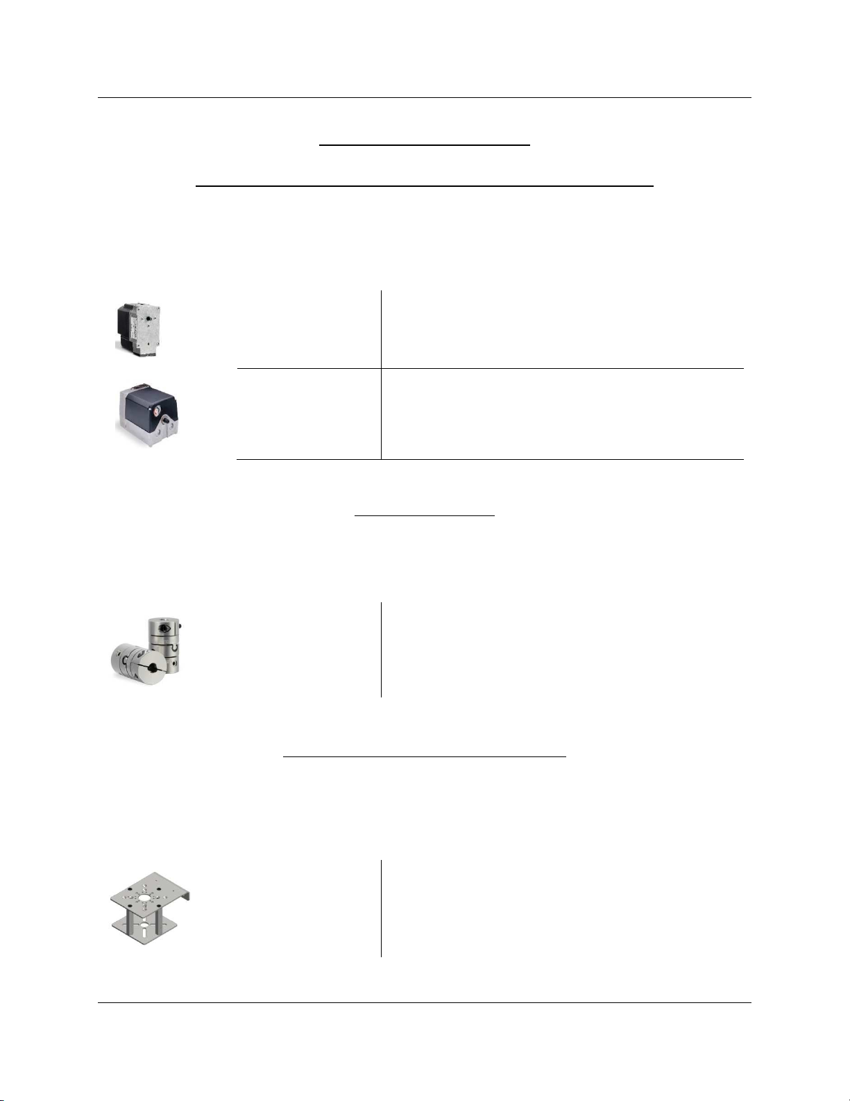
Couplings – Optional
Zero-lash, flexible couplings are available for SQM… actuators. For more information, refer to
Document No. CPBK-1000.
Cxx…
Flexible couplings for SQM… actuators
Actuator Mounting Bracket Kits - Optional
Modular bracket kits are available to assist in mounting an SQM… actuator to a variety of valves
or dampers. A coupling is necessary when using a modular bracket kit. For more information,
refer to Document No. CPBK-2000.
BR-AS…
to a variety of valves or dampers
SCC Inc. Page 5 Section 1
Modular bracket kits for mounting SQM… actuators
Technical Instructions LME Series
Document No. LME-1000
Flame Scanners
Flame Scanners – Qty (1) Required Unless Using a Flame Rod
Four flame scanners are available for use with the LME7. For technical information about these
flame scanners, refer to Document No. N7711 for the QRA4.U, Document No. N7719 for the
QRI… flame scanners, and Document No. N7712 for the QRA75.A17.
Ultraviolet (UV) flame scanner, non-self-checking,
QRA4.U
forward viewing, with ¾” NPSM connection, for use
with LME71 or LME73 base units
QRA75.A17
QRI2A2.B180B
QRI2B2.B180B
Ultraviolet (UV) flame scanner, self-checking, side
viewing, for use with LME75 base units
Infrared (IR) flame scanner, self-checking, forward
viewing, for use with LME75 base units
Infrared (IR) flame scanner, self-checking, side
viewing, for use with LME75 base units
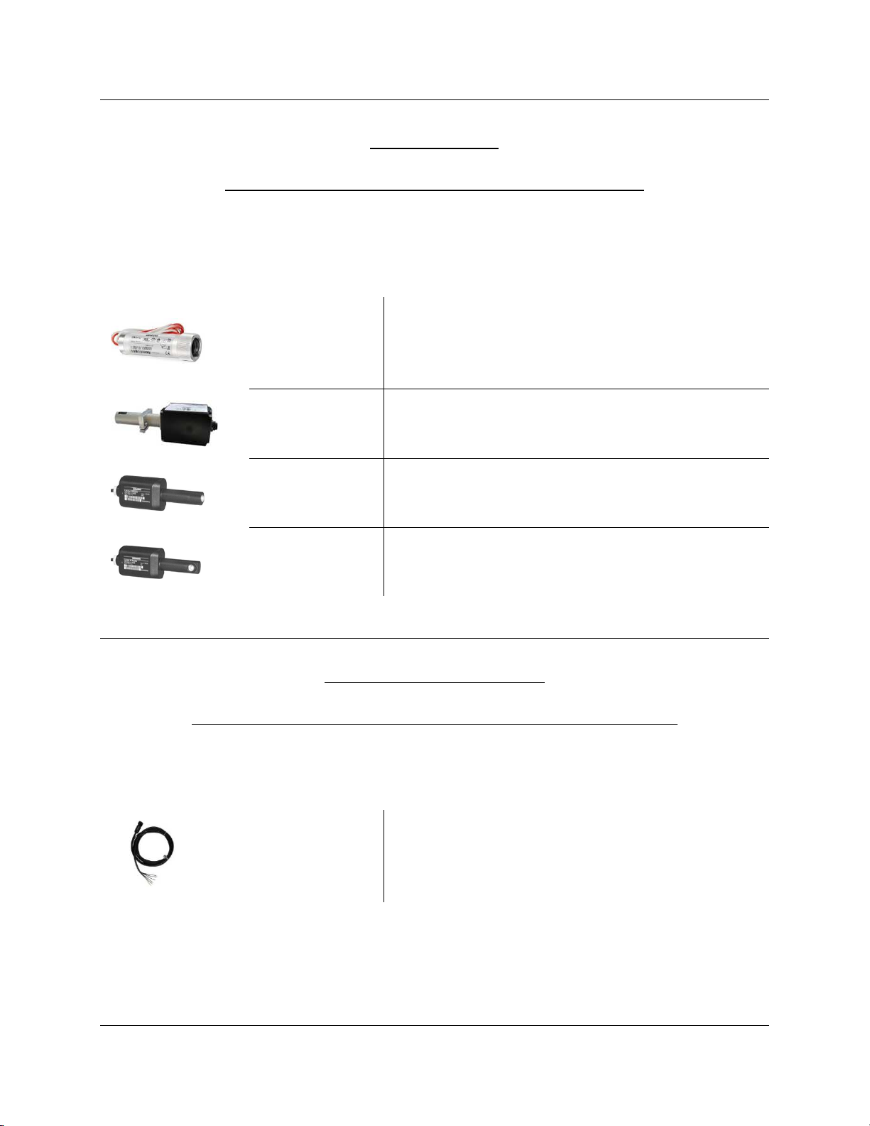
Flame Scanner Accessories
QRA75 Wiring Cable – Qty (1) Required per QRA75.A17 Flame Scanner
A pre-made 12 foot cable is required when using the QRA75.A17 flame scanner. For more
information, refer to Document No. N7712.
Pre-made 12 foot cable for use with the QRA75.A17
AGM23U
flame scanner. Supplied with 1/2” NPSM conduit
adapter
Section 1 Page 6 SCC Inc.
LME Series Technical Instructions
Document No. LME-1000
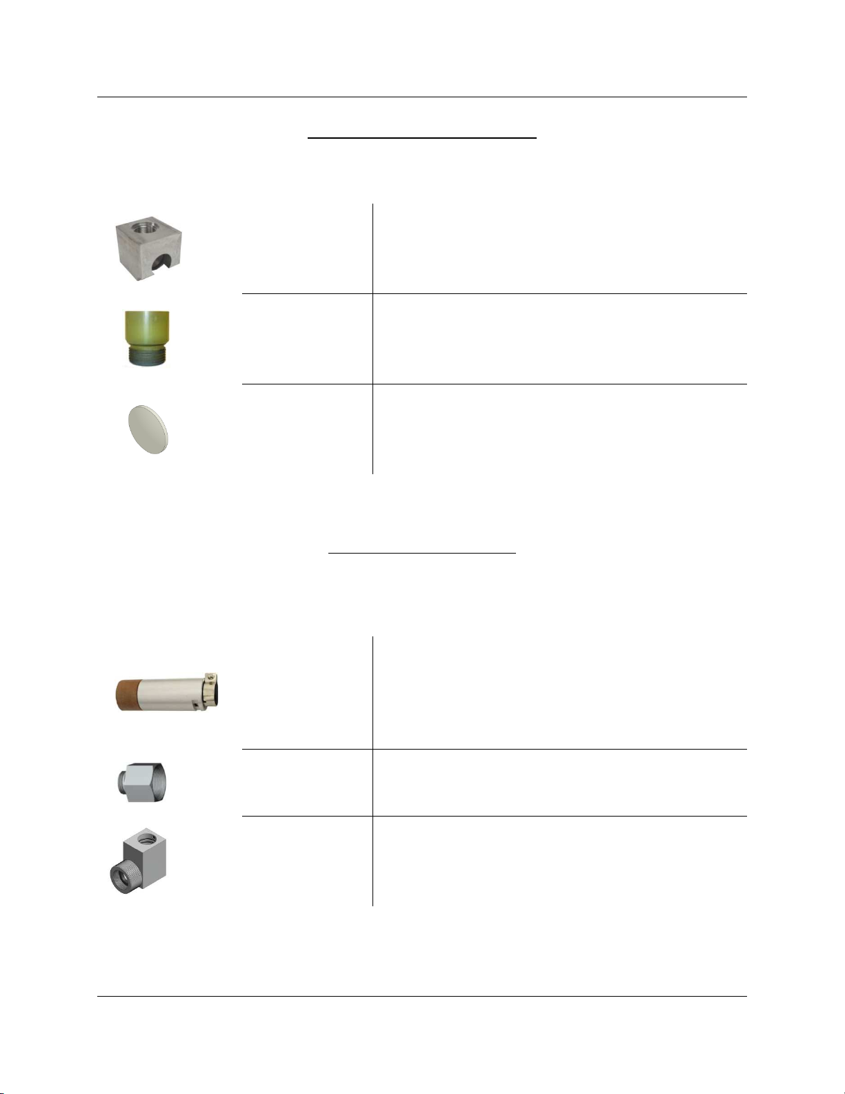
QRA75.A17 Accessories - Optional
Mounting accessories are available for the QRA75.A17 flame scanner. For more information,
refer to Document No. N7712.
Right angle adapter for mounting a QRA75 flame
AGG16.U
scanner. Comes with a 1” NPSM female thread
connection
Thermal barrier for use with the QRA75 flame
THERMAL-1X75
scanner along with accessory AGG16.U. Adapts a 1”
NPSM thread to a female 3/4” NPT connection
Magnifying lens with spring washer and O-ring for
AGG03
increased sensitivity, to be mounted inside thermal
barrier THERMAL-1X75
QRI… Accessories - Optional
Mounting accessories are available for both the forward viewing and side viewing QRI… flame
scanners. For more information, refer to Document No. N7719.
Kit for mounting forward viewing scanner
QRI2A2.B180B on a flame tube. Comes with clamp,
AGG2.110
mounting sleeve, thermal barrier with 3/4” NPSM
connection, and heat insulation glass
Pg9 thread to 1/2” NPSM conduit connection
AGG2.120
adapter for use with any QRI… flame scanner
Right angle adapter for mounting side viewing
AGG90.U
scanner QRI2B2.B180B on a flame tube. Comes
with 3/4” NPSM female thread connection
SCC Inc. Page 7 Section 1
Technical Instructions LME Series
Document No. LME-1000
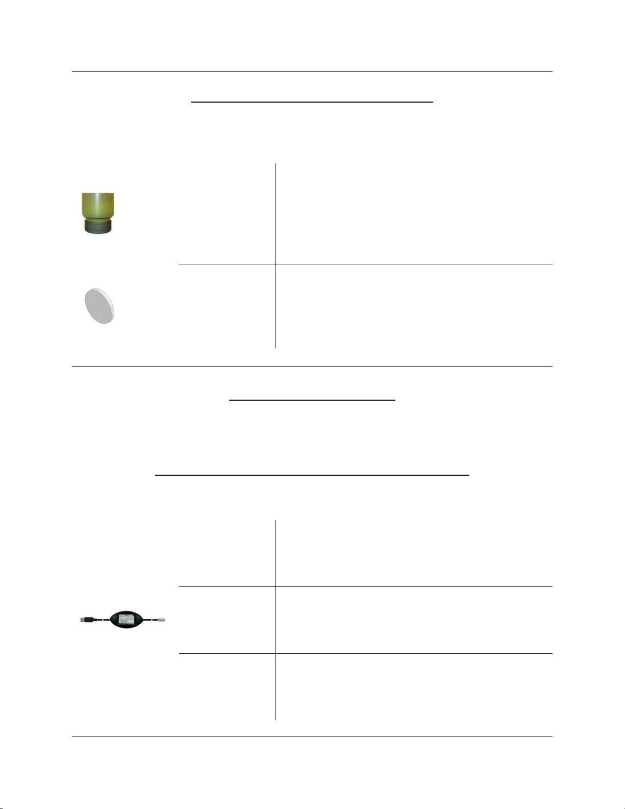
Additional Flame Scanner Accessories – Optional
Additional accessories are available for flame scanners to prevent heat from getting to the
scanner. For more information, refer to Document No. N7711 and Document No. N7712.
Thermal barrier for use with the QRA4.U flame
scanner, and QRI2B2.B180B flame scanner when
THERMAL-
used with right angle adapter AGG90.U. Adapts a
75X75
3/4” NPSM thread to a female 3/4” NPT connection.
Rated for scanner tube temperatures up to 250 °F
Heat insulating lens with spring washer and O-ring,
for applications where the temperature at the
AGG02
scanner will exceed 176 °F. Can be mounted inside
thermal barriers THERMAL-75X75 or THERMAL-1X75
ACS410 Software for Laptop
The ACS410 software for the LME7 offers many features including parameter backups, startup
reports, and trending. The software may be downloaded at www.scccombustion.com.
ACS410 Cables – Qty (1) Required if Using the ACS410 Software
To use the ACS410 software, cables are necessary to connect the LME7 to a PC.
User-level PC interface module and cable. Permits
access to user level parameters only without the
ability to perform parameter backups
Service-level PC interface module and cable.
Permits access to user and service level parameters
and the ability to perform parameter backups
OCI410.20
OCI410.30
OEM-level PC interface module and cable. Permits
OCI410.40
access to all parameters and the ability to perform
parameter backups
Section 1 Page 8 SCC Inc.
LME Series Technical Instructions
Document No. LME-1000
Enclosures
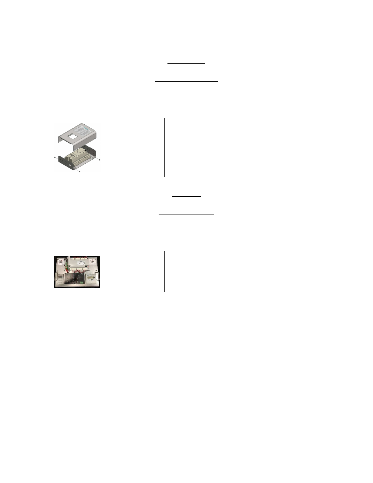
Enclosures - Optional
A small NEMA 1 enclosure is available for use with any LME7… base unit. Three ½” conduit
knockouts are available on both the top and the bottom of the enclosure.
LME7-ENC-KT
NEMA 1 enclosure for any LME7… base unit
Trainers
Trainers - Optional
Training units are available to train OEMs and field technicians how to program and use the
various features of the LME75 burner control.
TR-L75-1A
LME75 training unit, 110 VAC
SCC Inc. Page 9 Section 1
Technical Instructions LME Series
Document No. LME-1000
Mounting
LME7 Controller
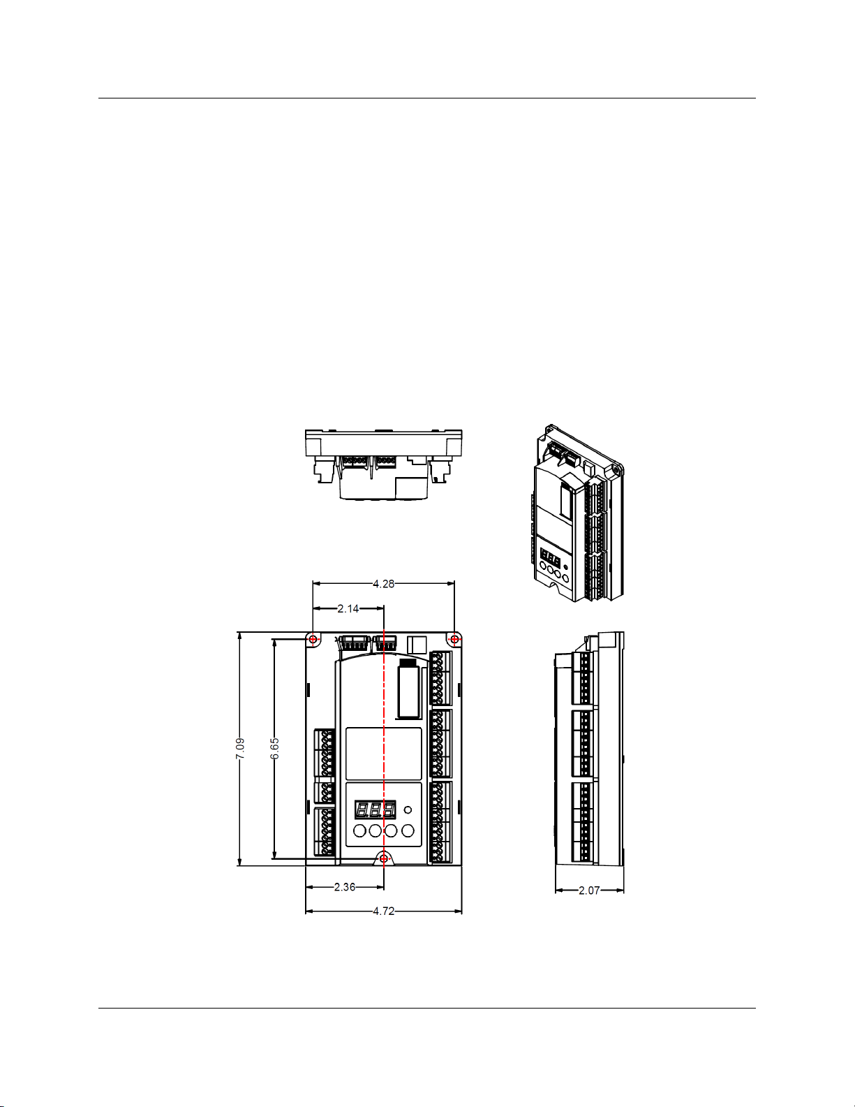
The LME7 must be mounted inside an enclosure that will protect it from dirt and moisture. The
unit should be mounted with three #8 screws (not provided). The panel, which the unit sits on,
should be drilled and tapped to accommodate these screws.
During the mounting process, consideration should be given to the various plugs and wires that
must be attached to the LME7. Electrical connections are made via plugs that are located in the
face of the unit with wires coming out to the top, left side, and right side of the unit. A space of
at least one inch is recommended above, to the left, and to the right of the LME7. The
recommended total space to leave for the LME7 is 8” x 6.75” x 3” because the overall
dimensions of the LME7 are 7.09” x 4.72” x 2.07”.
Figure 1-2: LME7 Dimensions (inches)
Section 1 Page 10 SCC Inc.
LME Series Technical Instructions
Document No. LME-1000
AZL23 Display
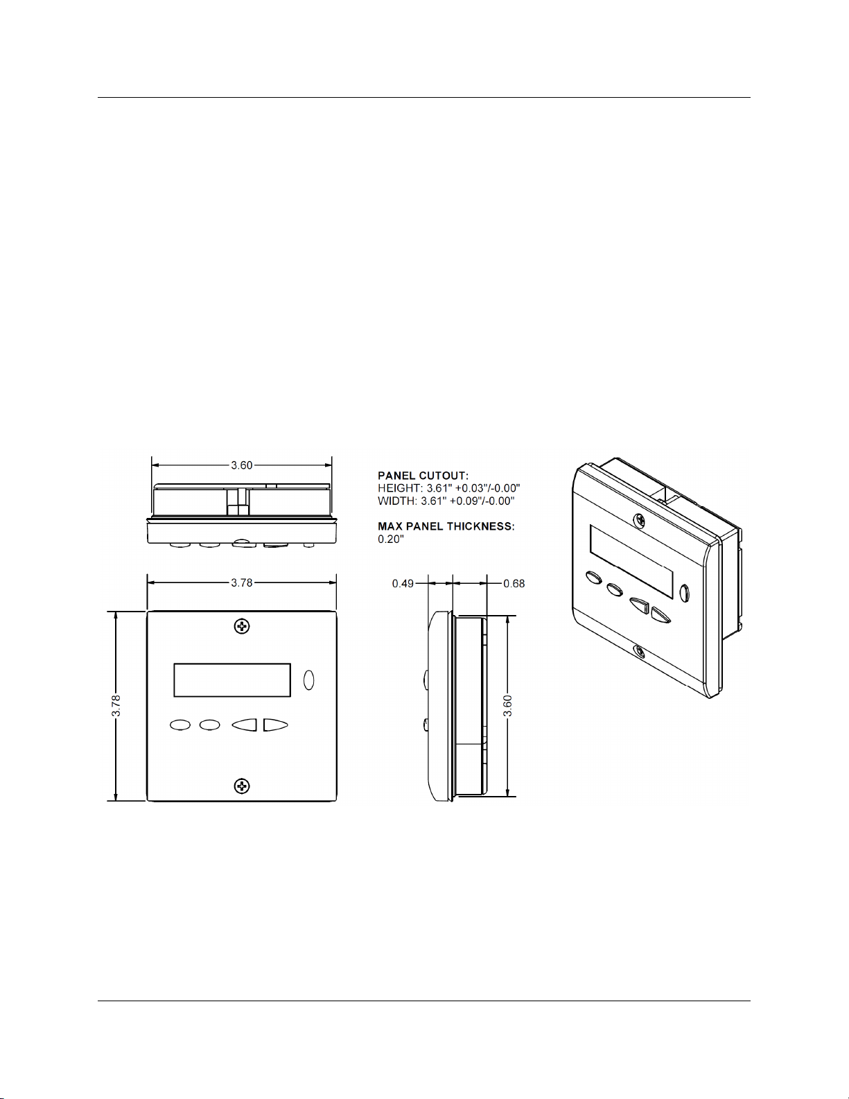
The AZL23 is designed to be mounted in a rectangular cutout through the face / door of an
electrical enclosure. It has one screw on the top and another on the bottom that engage small
plastic tabs which will swing out when the screw is tightened clockwise; the screw can be
loosened to retract the tab and increase clearance before tightening. The tab will pinch the
sheet metal of the enclosure door between itself and the AZL23 gasket. This facilitates easy
removal and replacement of the AZL23 since it is designed to be taken out of the enclosure face
and held in the hands for setup and commissioning.
The AZL23 connects to the LME7 at terminal X56 with cable TDCCOMBO. The AZL23 has an
IP54 rating when mounted in an electrical enclosure.
Figure 1-3: AZL23 Dimensions (inches)
SCC Inc. Page 11 Section 1

Technical Instructions LME Series
Document No. LME-1000
Important Safety Notes
• The LME7 is a safety device. Under no circumstances should the unit be modified or
opened. SCC Inc. will not assume responsibility for damage resulting from unauthorized
modification of the unit.
• All activities (mounting, installation, service work, etc.) must be performed by qualified
staff.
• Before performing any work in the connection area of the LME7, disconnect the unit
from the main supply (all-polar disconnection).
• Protection against electrical shock hazard on the LME7 and all other connected
electrical components must be ensured through good wiring and grounding practices.
• Fall or shock can adversely affect the safety functions of an LME7. Such units must not
be put into operation, even if they do not exhibit any apparent damage.
• Condensation and the entry of water into the unit must be avoided.
Section 1 Page 12 SCC Inc.
LME Series Technical Instructions
Document No. LME-1000
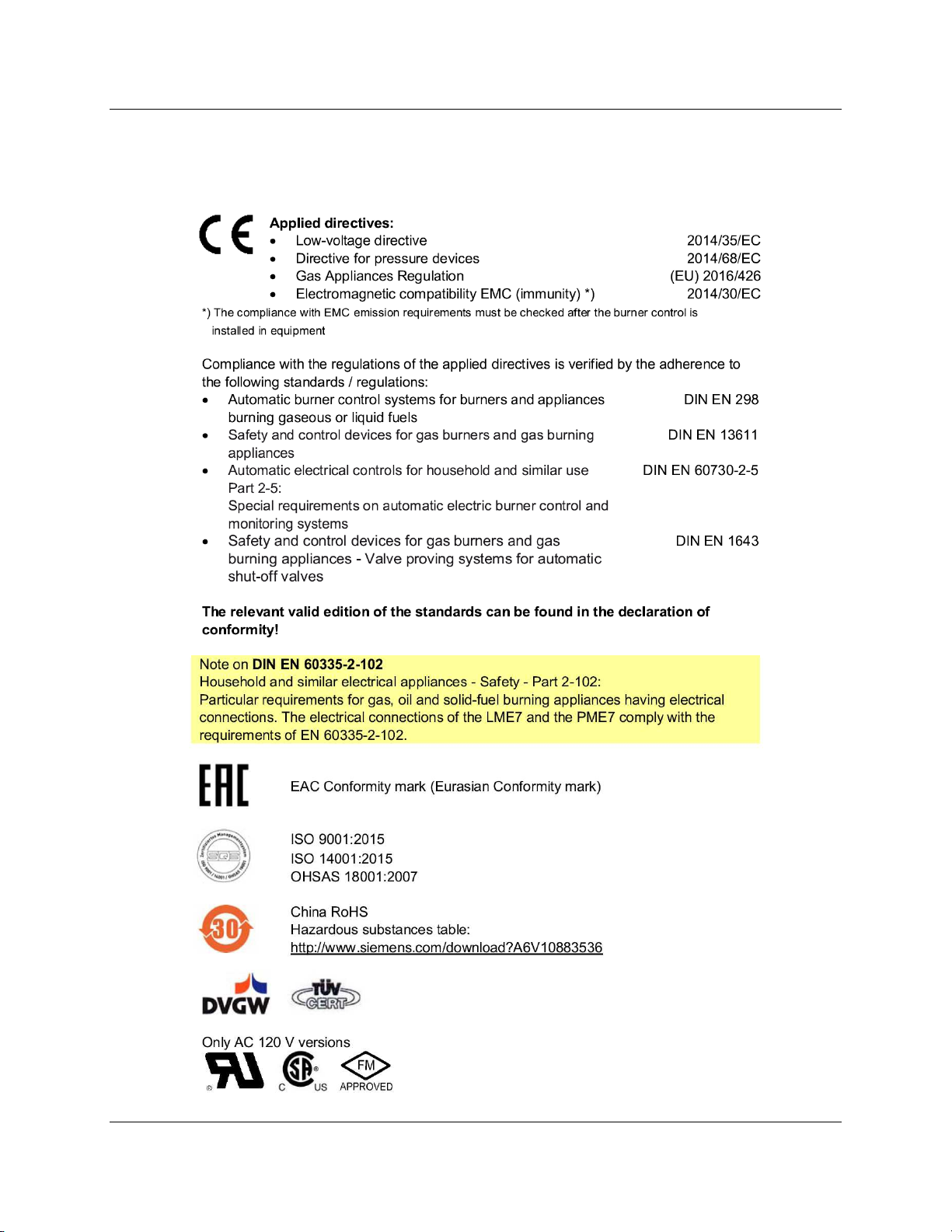
Approvals
The LME7 has the following standards and approvals:
SCC Inc. Page 13 Section 1

Technical Instructions LME Series
Document No. LME-1000
Intentionally Left Blank
Section 1 Page 14 SCC Inc.

Section 1
Overview
Section 2
LME71 Wiring,
Section 3
LME73 Wiring, Para
meters,
Section 4
LME75 Wiring, Parameters,
Section 5
Commissioning
Section 6
PWM Blowers
Section 7
Troubleshooting
Section 8
Modbus
Section 9
ACS410
Appendix A
Application Guide
Parameters, and
P
hase Diagrams
and Phase Diagrams
and Phase Diagrams

Section 1
Overview
Section
2 LME71 Wiring,
Parameters, and
Section 3
LME73 Wiring, Parameters,
Section 4
LME75 Wiring, Parameters,
Section 5
Commissioning
Section 6
PWM Blowers
Section 7
Troubleshooting
Section 8
Modbus
Se
ction 9
ACS410
Appendix A
Application Guide
hase Diagrams
P
and Phase Diagrams
and Phase Diagrams
LME Series
LME-1000
Technical Instructions
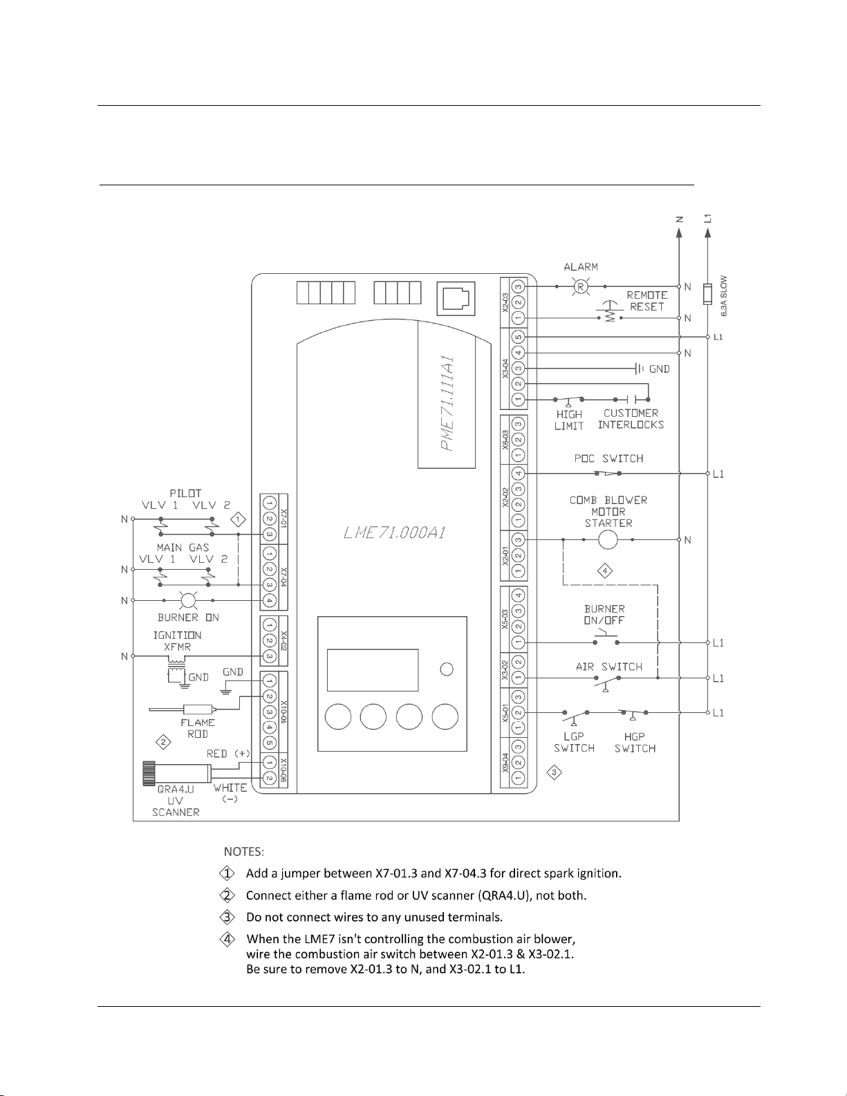
LME71 Wiring Diagrams
PME71.111A1 – Pilot or direct spark; with purge; no actuator control; no valve proving
SCC Inc. Page 1 Section 2
Technical Instructions L
Document No. LME-1000
u
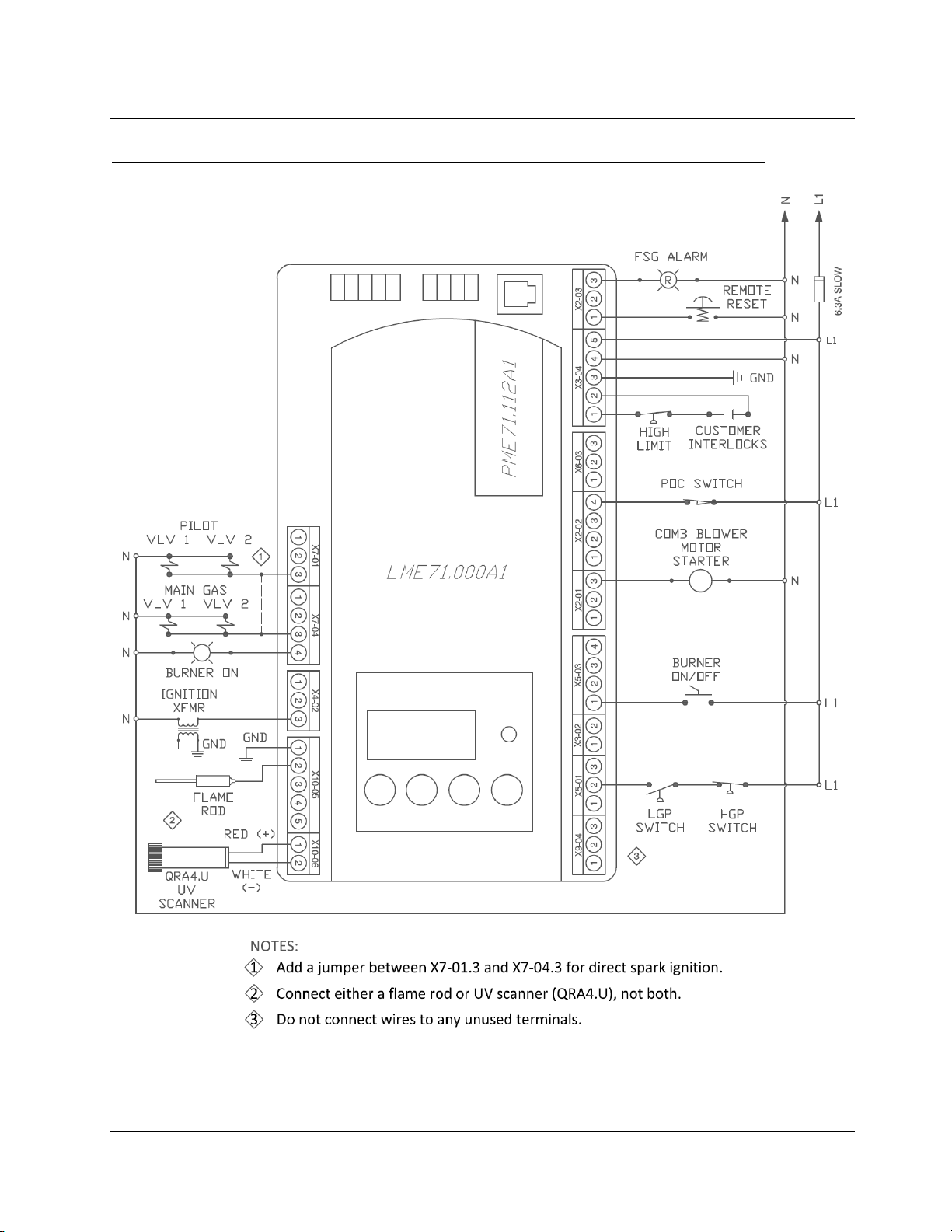
PME71.112A1 – Pilot or direct spark; no purge; no act
ator control; no valve proving
ME Series
Section 2 Page 2 SCC Inc.
LME Series
LME-1000
Technical Instructions
v
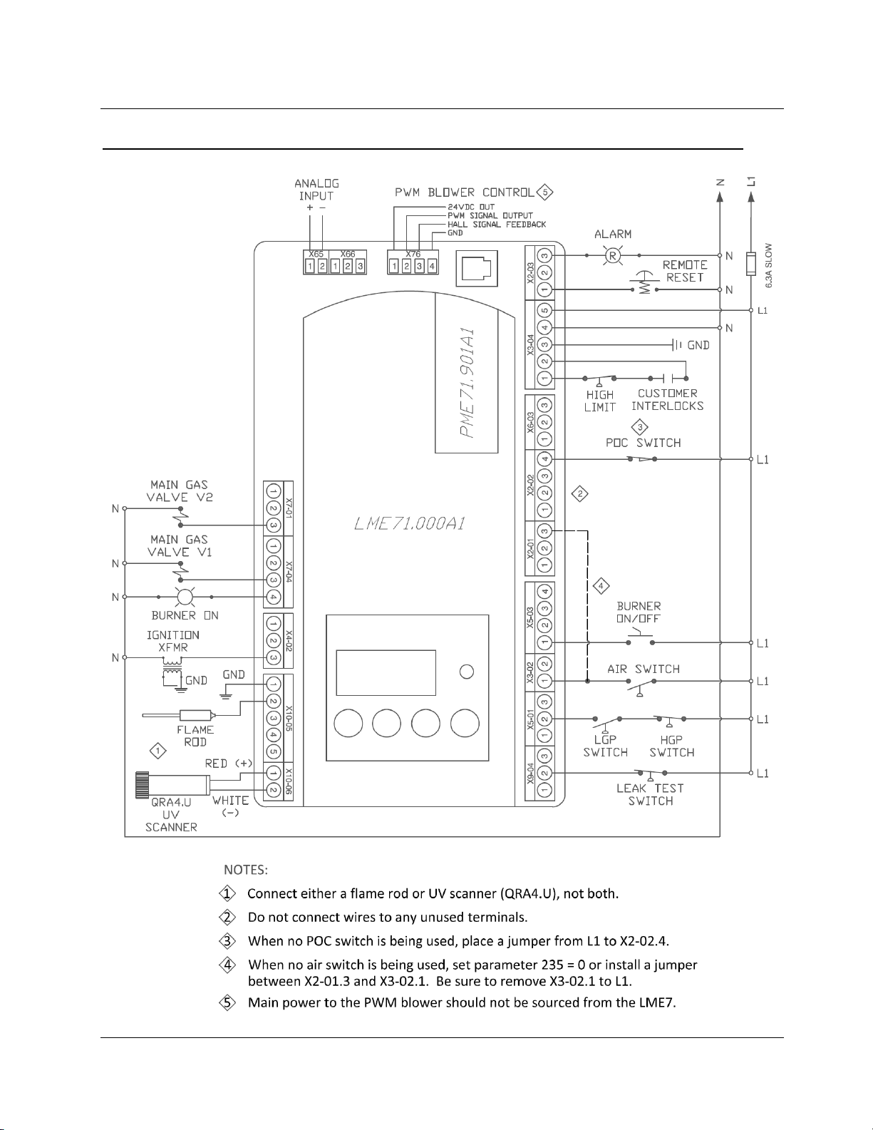
PME71.901A1 – PWM blower control; direct spark only;
alve proving; no actuator control
SCC Inc. Page 3 Section 2
LME Series
Used to perform parameter backups and restores.
display "rSt End".
000 Level: Parameter Backup / Restore / Change Passwords
LME71 Parameter List
Technical Instructions
LME-1000
Parameter
Number
041 Service Level PW 7173 Any 4 characters
042 OEM Level PW L7unI Any 5 characters
060 Backup / Restore S
Parameter Name
Shaded Parameters = Frequently Used
PW Level Default Range Description
The service level password can be changed here. It must be exactly 4 characters in length. Enter the
O
Backup - 0
Restore - 0
0-1
current password, then enter the new password twice to change it (c = current, n = new, r = repeat).
The OEM level password can be changed here. It must be exactly 5 characters in length. Enter the current
password, then enter the new password twice to change it (c = current, n = new, r = repeat).
Backup: Transfer LME7 parameters to PME7. Restore: Transfer PME7 parameters to LME7.
Set parameter to 1 and press the info button to begin the backup or restore. Once a parameter backup is
successful, the screen will display "bAC End". Once a parameter restore is successful, the screen will
100 Level: General Information / Display Mode
LEGEND - Password Level: S = Service; O = OEM; S/O = View - Service, Write - OEM; Info = Info Menu; Ser = Service Menu
102 Production Date Date that the LME7 was produced in the DD.MM.YY format.
103 Serial Number Serial number of the LME7.
Info
113 Burner ID Not set 0-99999999
140 Display Mode S
164 Startups
166 Total Startups Displays the total number of startups. Not resettable.
Info
170 Number of Relay Cycles
171 Max Relay Cycles Displays the maximum number of relay cycles allowed on the internal relays of the LME7.
111 - 1
112 - 1
901 - 4
Read only
Reset only
Read only
1-4
The burner ID can be viewed through the AZL23 but can only be set using the ACS410 software. The
burner ID must be all digits (no letters), from 1-8 digits in length. Typically the burner serial number is
used. This serves as an identifier for the parameter set. The burner ID must be set in order to perform a
parameter backup to a PC using the ACS410 software. Parameter backups to the PME7 program module
can be made without setting the burner ID.
Sets what will be displayed by the LME7 integral display.
1 = phase
2 = flame signal (QRA… flame scanner or flame rod)
3 = not used
4 = load
Displays the total number of startups. To reset this value, press and hold the info button until the value
begins to flash, then let go. The value will automatically change to 0. Press the info button again to
confirm the reset.
Displays the number of cycles on different internal relays in the LME7.
Index 00 = K12 relay cycles
Index 01 = K11 relay cycles
Index 02 = K2 relay cycles
Index 03 = K1 relay cycles
PME71.
111A1
PME71.
112A1
• • •
• • •
• • •
• • •
• • •
• • •
• • •
• • •
• • •
• • •
• • •
PME71.
901A1
SCC Inc. Page 4 Section 2

LME Series
Once the LME7 reaches phase 22 for the second time (between phases 24 and 30), this sets the length of
due to lack of air pressure. As soon as the switch is made, the sequence progresses.
opened. Sets the length of phase 38.
When activated, this forces the LME7 to shut the burner down every 24 hours of uninterrupted operation.
The burner will automatically restart afterwards. The purpose of the shutdown is to check and cycle safety
1 = activated
Technical Instructions
LME-1000
Parameter
Number
224
225 Prepurge Time
226 Pre-Ignition Time 3.087 sec 1.029-37.485 sec
230
231
234 Postpurge Time
235 Air Pressure Switch 0 0-1
237 POC Switch S 1 0-2
Parameter Name
Time Air Pressure
Switch
Pilot / Main
Stabilization Time
Pilot and Main Overlap
Time
Shaded Parameters = Frequently Used
PW Level Default Range Description
13.818 sec 0-13.818 sec
S/O
111 - 29.106 sec
901 - 19.404 sec
111 - 3.234 sec
112 - 3.234 sec
901 - 15.582 sec
9.996 sec 0-74.97 sec
111 - 19.404 sec
901 - 4.851 sec
0-1237 sec
3.234-74.97 sec
0-1237 sec Sets the postpurge time (length of phase 74).
LEGEND - Password Level: S = Service; O = OEM; S/O = View - Service, Write - OEM; Info = Info Menu; Ser = Service Menu
200 Level: Burner Control
time the LME7 will wait for air pressure switch input X3-02.1 to become energized before a lockout occurs
Sets the prepurge time (length of phase 30). The LME7 has a base prepurge time of 2.1 seconds. This
setting adds seconds to the base time.
The period of time that the ignition transformer (output X4-02.3) is energized before the main valves are
On PME71.111A1 and PME71.112A1, this setting defines the pilot stabilizing period if a pilot is used.
During this period, only the pilot valve is open. The spark is de-energized.
On PME71.901A1, this setting defines the main stabilizing period. During this time, only the main valves
are open. The spark is de-energized. Sets the length of phase 44.
When a fuel train with a pilot is used, this setting defines the overlap of the pilot (output X7-01.3) and the
main fuel valves (output X7-04.4). After this time expires, the pilot is de-energized. Sets the length of
phase 50.
This setting activates or deactivates the air pressure switch input X3-02.1.
0 = deactivated
1 = activated
This setting defines the function of POC switch input X2-02.4.
0 = deactivated
1 = activated (verify POC switch is closed on startup and shutdown)
2 = activated (verify POC switch is closed on startup and shutdown, and open during operation)
PME71.
111A1
PME71.
112A1
• •
• • •
• •
• •
• •
PME71.
901A1
•
•
•
239 Forced Intermittent 0 0-1
S/O
240 Repetition Flame 0
Index 00 = 0-2
Index 01 = 0-4
devices. The PME73.840A1 will recycle every 24 hours.
0 = deactivated
This sets the numbers of times a flame failure must occur before causing a lockout. Most North American
codes require 1.
Index 00 = flame failures during operation
Index 01 = flame failures during main trial for ignition
0 = no repetitions
1 = no repetitions
2 = 1 repetition
3 = 2 repetitions
4 = 3 repetitions
• •
• • •
SCC Inc. Page 5 Section 2

LME Series
Determines at which point during the burner's sequence that valve proving will be performed. Used in
1 = valve proving on shutdown
Determines at which point during the burner's sequence that valve proving will be performed. Used in
1 = valve proving on startup and shutdown
Flame Failure Response
Technical Instructions
LME-1000
Parameter
Number
241.00
241.01 Valve Proving Setup 1 1 0-1
241.02 Valve Proving Setup 2 0 0-1
242 VP Evacuation Time 2.646 sec 0-2.646 sec
243 VP Upstream Test 10.290 sec 1.029-37.485 sec
244 VP Fill Time 2.646 sec 0-2.646 sec
245 VP Downstream Test 10.290 sec 1.029-37.485 sec
247 Intermittent Pilot 0 0-1
Parameter Name
Valve Proving
Activation
Shaded Parameters = Frequently Used
PW Level Default Range Description
0 0-1
S/O
LEGEND - Password Level: S = Service; O = OEM; S/O = View - Service, Write - OEM; Info = Info Menu; Ser = Service Menu
This setting determines if gas valve proving (leak testing) will be performed. Gas valve proving can be
performed on startup, shutdown, or both depending on the settings of parameters 241.01 and 241.02.
0 = deactivated
1 = activated
conjunction with parameter 241.02.
0 = valve proving on startup
conjunction with parameter 241.01.
0 = valve proving according to parameter 241.01
If valve proving is performed, this specifies the length of time that the downstream valve (V2) is energized
(output X7-01.3). This will evacuate any gas that might exist between the gas valves. Sets the length of
phase 80.
If valve proving is performed, this specifies the length of time that both the upstream and downstream
valves are closed. If the pressure between the valves rises during this period (enough to open the NC
valve proving pressure switch), then the upstream valve is leaking and the LME7 will lockout. A longer
time period will produce a more sensitive test. Sets the length of phase 81.
If valve proving is performed, this specifies the length of time that the upstream valve (V1) is energized
(output X7-04.4). This will fill the volume between the main gas valves to line pressure. Sets the length of
phase 82.
If valve proving is performed, this specifies the length of time that both the upstream and downstream
valves are closed. If the pressure between the valves falls during this period (enough to close the NC valve
proving pressure switch), then the downstream valve is leaking and the LME7 will lockout. A longer time
period will produce a more sensitive test. Sets the length of phase 83.
Sets the type of pilot being used. If set to 1, the pilot valve will remain open from phase 40 to the end of
main operation (oP1).
0 = interrupted pilot
1 = intermittent pilot
PME71.
111A1
• •
PME71.
112A1
PME71.
901A1
•
•
•
•
•
•
•
Sets the flame failure response time (FFRT). The FFRT is the maximum length of time that the flame signal
can go away before a lockout occurs. This setting also doubles as the length of time the signal from the air
254
257 Trial for Ignition
Time
(FFRT)
1 0-1
111 - 4.116 sec
112 - 4.116 sec
901 - 2.205 sec
0-13.23 sec
pressure switch can go away before a lockout occurs. On PME71.901A1, the FFRT is fixed at 1 second.
0 = 1 second
1 = 3 seconds
On PME71.111A1 and PME71.112A1, this setting defines the overlap of the spark (output X4-02.3) and the
pilot valve (output X7-01.3) if a pilot is used.
On PME71.901A1, this setting defines the overlap of the spark (output X4-02.3) and the main valves.
After this time expires, the spark is de-energized. The LME7 has a base time of 0.3 seconds. This setting
adds seconds to the base time. Sets the length of phase 40.
• •
• • •
SCC Inc. Page 6 Section 2
 Loading...