

Siemens LME21.230A2, LME11.230A2, LME21.130A2, LME21.330A1, LME21.330A2 Installation Manuals
...
CC1N7101en
27.11.2008
Building Technologies
HVAC Products
7
101
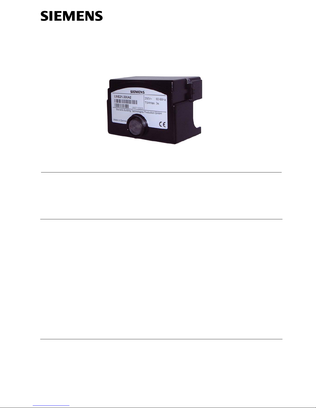
Burner Controls LME...
Burner controls for the supervision of 1- or 2-stage gas or gas / oil burners of
small to medium capacity, operation, with or without fan in intermittent.
The LME… and this Data Sheet are intended for use by OEMs which integrate the
burner controls in their products.
Use, features
LME… burner controls are used for the startup and supervision of 1- or 2-stage gas or
gas / oil burners in intermittent operation. The flame is supervised by an ionization
probe or flame detector QRA… with ancillary unit AGQ3…A27 for gas / oil forced draft
burners or blue–burning flames with blue-flame detectors QRC...
In terms of housing dimensions, the LME... are identical with the LGB… and LMG…
burner controls (refer to «Type summary»).
- For gas burners with or without fan to EN 298: 2003
- For gas burners with fans conforming to EN 676
- For oil burners to EN 230: 2005
- Undervoltage detection
- Air pressure supervision with functional check of the air pressure switch during
startup and operation
- Electrical remote reset facility
- Multicolor indication of fault status and operational status messages
- Limitation of the number of repetitions
- Accurate control sequence thanks to digital signal handling
- Controlled intermittent operation after 24 hours of continuous operation
Supplementary documentation
Product Range Overview LME…............................................................................ Q7101
Use
Features

2/25
Building Technologies CC1N7101en
HVAC Products 27.11.2008
Warning notes
To avoid injury to persons, damage to property or the environment, the following
warning notes must be observed!
Do not to open, interfere with or modify the unit!
• All activities (mounting, installation and service work, etc.) must be performed by
qualified staff
• Before making any wiring changes in the connection area, completely isolate the
plant from mains supply (all-polar disconnection). Ensure that the plant cannot be
inadvertently switched on again and that it is indeed dead. If not observed, there is
a risk of electric shock hazard
• Ensure protection against electric shock hazard by providing adequate protection
for the burner control’s connection terminals
• Check the connecting lines of the air pressure switch for short-circuits (connection
terminals 3, 6 and 11)
• Press the lockout reset button / operation button of LME... or the AGK20… lockout
reset button extension only manually (applying a force of no more than 10 N) without using any tools or pointed objects
• Fall or shock can adversely affect the safety functions. Such units must not be put
into operation, even if they do not exhibit any damage
• Each time work has been carried out (mounting, installation, service work, etc.),
check to ensure that wiring is in an orderly state and make the safety checks as
described in «Commissioning notes»
Engineering notes
• When used in connection with actuators, there is no position feedback signal from
the actuator to the burner control
• When used in connection with actuators, the requirements of applicable norms and
regulations must be observed
• The running times of the actuators must match the burner control’s program. An
additional safety check of the burner control together with the actuators is required
• When substituting burner controls type LGB… or LMG… by LME…, the AGQ1… or
AGQ2… ancillary unit must be replaced by the AGQ3…A27
Mounting notes
• Ensure that the relevant national safety regulations are complied with
3/25
Building Technologies CC1N7101en
HVAC Products 27.11.2008
Installation notes
• Always run the high ignition cables separate from the unit and other cables while
observing the greatest possible distance
• Do not mix up live and neutral conductors
• Install switches, fuses, earthing, etc., in compliance with local regulations
• The connection diagrams show the burner controls with earthed neutral conductor.
In networks with non-earthed neutral conductor and ionization current supervision,
terminal 2 must be connected to the earth conductor via an RC unit (type reference
ARC 4 668 9066 0). It must be made certain that local regulations are complied
with (e.g. protection against electric shock hazard) since AC 120 V (50 / 60 Hz) or
AC 230 V (50 / 60 Hz) mains voltage produces peak leakage currents of 2.7mA
• Make certain that the maximum permissible current rating of the connection termi-
nals will not be exceeded
• Do not feed external mains voltage to the control outputs of the unit. When testing
the devices controlled by the burner control (fuel valves, etc.), the LME… must not
be connected
• In the case of burners with no fan motor, an AGK25 must be connected to terminal
3 of the unit, or else the burner cannot reliably be started up
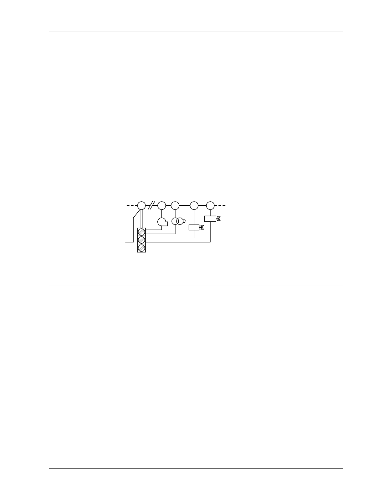
• For safety reasons, feed the neutral conductor to terminal 2. Connect the burner
components (fan, ignition transformer and fuel valves) to the neutral distributor as
shown below in figure. The connection between neutral conductor and terminal 2 is
prewired in the base
Example
23
7
4
5
BV2
BV1
Z
M
N
7101a05/0804
Correct wiring of neutral conductors!
Electrical connection of flame detectors
It is important to achieve practically disturbance- and loss-free signal transmission:
• Never run detector cables together with other cables
– Line capacitance reduces the magnitude of the flame signal
– Use a separate cable
• Observe the permissible length of the detector cables (refer to «Technical data»)
• The ionization probe is not protected against electric shock hazard
• Locate the ignition electrode and the ionization probe such that the ignition spark
cannot arc over to the ionization probe (risk of electrical overloads) and that it cannot adversely affect the supervision of ionization
• Insulation resistance
– Must be a minimum of 50 MΩ between ionization probe and ground
– Soiled detector holders reduce the insulation resistance, thus supporting cree page currents
• Earth the burner in compliance with the relevant regulations; earthing the boiler
alone does not suffice
Legend
BV... Fuel valve
M Fan motor
Z Ignition transformer
4/25
Building Technologies CC1N7101en
HVAC Products 27.11.2008
Commissioning notes
• When commissioning the plant for the first time or when doing maintenance work,
make the following safety checks:
Safety check to be carried out Anticipated response
a) Burner startup with previously inter-
rupted line to the flame detector
LME11… / LME41.051...:
Max. 3 repetitions
LME2… / LME41.052... / LME41.053... / LME41.054... / LME41.071...
/ LME41.09... / LME44...:
Lockout at the end of «TSA»
b) Burner operation with simulated loss of
flame. For that purpose, cut off the fuel
supply
LME11… / LME41.051...:
• Establishment of flame at the end of «TSA» → Max. 3 repetitions
• No establishment of flame at the end of «TSA» → Lockout
LME2… / LME44...:
Lockout
LME41.052... / LME41.053... / LME41.054... / LME41.071... /
LME41.09...:
Repetition
c) Burner operation with simulated air
pressure failure
Immediate lockout
LME41...:
Safety shutdown / restart
5/25
Building Technologies CC1N7101en
HVAC Products 27.11.2008
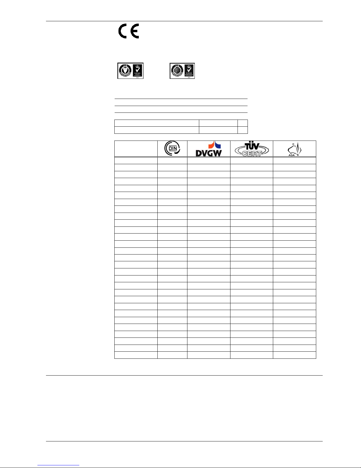
Standards and certificates
Conformity to EEC directives
- Electromagnetic compatibility EMC (immunity)
- Directive for gas-fired appliances
- Low-voltage directive
- Directive for pressure devices
2004/108/EC
90/396/EEC
2006/95/EC
97/23/EC
ISO 9001: 2000
Cert. 00739
ISO 14001: 2004
Cert. 38233
Identification code to EN 298 / EN 230
LME11…
F M C L X N
LME21… / LME22… / LME23…
F T L L X N
LME41...
A M C L X N
LME44…
A B L L X N
Type
LME11.230A2
--- x x ---
LME11.330A2
--- x x x
LME21.130A1
x x x ---
LME21.130A2
x x x x
LME21.230A2
x x x x
LME21.330A1
x x x ---
LME21.330A2
x x x x
LME21.350A1
x x x ---
LME21.350A2
x x x x
LME21.550A2
x x x x
LME22.131A2
x x x x
LME22.231A2
x x x x
LME22.232A2
x x x x
LME22.233A2
x x x x
LME22.331A1
x x x ---
LME22.331A2
x x x x
LME22.333A2
x x x ---
LME23.331A2
x x x x
LME23.351A2
x x x x
LME41.051A2
--- x x ---
LME41.052A2
--- x x ---
LME41.053A2
--- x x ---
LME41.054A2
--- x x ---
LME41.071A2
--- x x ---
LME41.091A2
--- x x ---
LME41.092A2
--- x x ---
LME44.056A2
--- x x x
LME44.057A1
--- x x ---
LME44.057A2
--- x x x
Service notes
• Use the KF8872 service adapter for short periods of time only
6/25
Building Technologies CC1N7101en
HVAC Products 27.11.2008
Life cycle
Burner controls has a designed lifetime* of 250,000 burner startup cycles which, under
normal operating conditions in heating mode, correspond to approx. 10 years of usage
(starting from the production date given on the type field). This lifetime is based on the
endurance tests specified in standard EN230 / EN298 and the table containing the
relevant test documentation as published by the European Association of Component
Manufacturers (Afecor) (www.afecor.org
).
The designed lifetime is based on use of the burner controls according to the manufacturer’s Data Sheet. After reaching the designed lifetime in terms of the number of
burner startup cycles, or the respective time of usage, the burner control is to be replaced by authorized personnel.
* The designed lifetime is not the warranty time specified in the Terms of Delivery
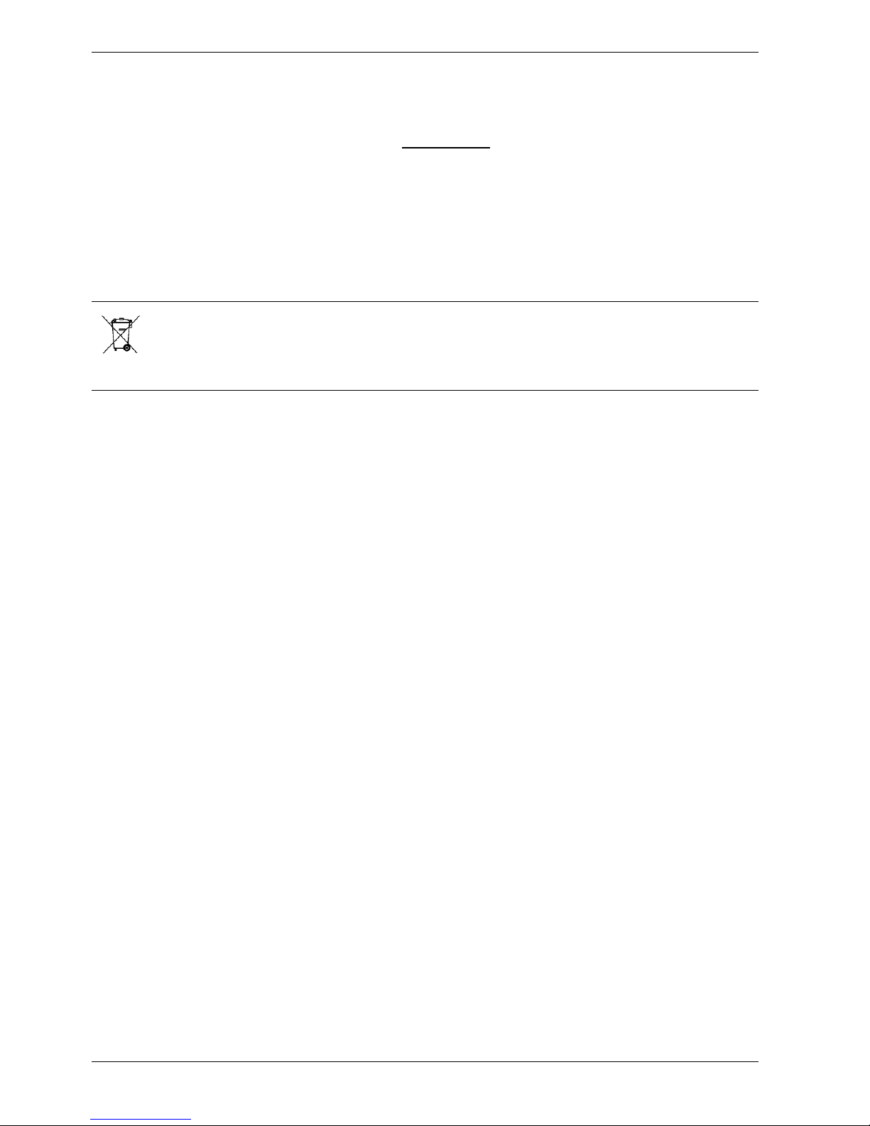
Disposal notes
The unit contains electrical and electronic components and must not be disposed of
together with domestic waste.
Local and currently valid legislation must be observed.
Mechanical design
• Units of plug-in design like their predecessor types LGB... and LMG... (refer to
«Dimensions»)
• The housing is made of impact-proof, heat-resistant and flame-retarding plastic. It
is of plug-in design and engages audibly in the base
• The housing accommodates the
- microcontroller for the control sequence and the control relays for load control
- electronic flame signal amplifier (ionization)
- lockout reset button with its integrated 3-color signal lamp (LED) for operational
status and fault status messages and the socket for connecting the OCI400 inter face adapter or the AGK20... lockout reset button extension
• Multicolor indication for operational status and fault status messages
• Transmission of operational status and fault status messages and detailed service
information via additional OCI400 interface adapter and ACS410 PC Windows
software
• Burner capacity unlimited (thermal output on startup ≤ 120 kW)
• 3 repetitions in the event of loss of flame during operation (LME11… /
LME41.051…)
• Repetition in the event of loss of flame during operation (LME41.052… /
LME41.053… / LME41.054… / LME41.071… / LME41.091… / LME41.092…)
LME...
Indication and
diagnostics
Versions
7/25
Building Technologies CC1N7101en
HVAC Products 27.11.2008
Type summary (other types of burner controls on request)
The type references given below apply to the LME… burner control without plug-in
base and without flame detector. For ordering information on plug-in bases and other
accessories, refer to «Ordering».
Flame detector
Type
reference
Main
voltage
tw
approx.
s
t1
min.
s
TSA
max.
s
t3n
approx.
s
t3
approx.
s
t4
approx.
s
t10
min.
s 3)
t11
min.
s 1)
t12
min.
s 1)
Repetition
For
replacing of
Burner controls for 1-stage burners (up to 120 kW output)
LME11.230A2
AC230V
2.5 20 3 2 2 --- 5 --- --- 3x
---
Ionization probe
(ION)
LME11.330A2
AC230V
2.5 30 3 2 2 --- 5 --- --- 3x
---
Burner controls for 2-stage burners, without actuator control
LME21.130A1
AC 120 V
2.5 7 3 2 2 8 5 --- --- ---
LGB21.130A17
LME21.130A2
AC 230 V
2.5 7 3 2 2 8 5 --- --- ---
LGB21.130A27
LMG21.130B27
LME21.230A2
AC 230 V
2.5 20 3 2 2 8 5 --- --- ---
LGB21.230A27
LMG21.230B27
LME21.330A1
AC 120 V
2.5 30 3 2 2 8 5 --- --- ---
---
LME21.330A2
AC 230 V
2.5 30 3 2 2 8 5 --- --- ---
LGB21.330A27
LMG21.330B27
LME21.350A1
AC 120 V
2.5 30 5 4 2 10 5 --- --- ---
LGB21.350A17
LME21.350A2
AC 230 V
2.5 30 5 4 2 10 5 --- --- ---
LGB21.350A27
LMG21.350B27
Ionization probe
(ION) or flame
detector
QRA...
4)
with
AGQ3...A27
LME21.550A2
AC 230 V
2.5 50 5 4 2 10 5 --- --- ---
LGB21.550A27
Burner controls for 2-stage burners, with actuator control
LME22.131A2
AC 230 V
2.5 7 3 2 3 8 3 12 12 ---
LGB22.130A27
LMG22.130B27
LME22.231A2
AC 230 V
2.5 20 3 2 3 8 3 12 12 ---
---
LME22.232A2
AC 230 V
2.5 20 3 2 3 8 3 16.5 16.5 ---
LGB22.230A27
LMG22.230B27
LME22.233A2
AC 230 V
2.5 20 3 2 3 8 3 30 30 --- LMG22.233B27
LME22.331A1
AC 120 V
2.5 30 3 2 3 8 3 12 12 ---
---
LME22.331A2
AC 230 V
2.5 30 3 2 3 8 3 12 12 ---
LGB22.330A27
LMG22.330B27
Ionization probe
(ION) or flame
detector
QRA... 4) with
AGQ3...A27
LME22.333A2
AC 230 V
2.5 30 3 2 3 8 3 30 30 ---
---
Burner controls for 2-stage burners, with actuator control
LME23.331A2
AC 230 V
2.5 30 3 2 3 8 3 12 12 --- LGB32.330A27
Blue flame
detector QRC…
LME23.351A2
AC 230 V
2.5 30 5 4 1 10 3 12 12 ---
LGB32.350A27
Legend
tw Waiting time 1) Max. running time available for actuator «SA»
TSA Safety time The actuator running time must be shorter
t1 Prepurge time 2) t22 + response time of flame relay
t3 Preignition time 3) Max. 65 s
t3n Postignition time 4) Only used for AC 230 V
t4 Interval between ignition «Off» and «BV2»
t10 Specified time for air pressure signal
t11 Programmed opening time for actuator «SA»
t12 Programmed closing time for actuator «SA»
t22 2nd safety time
8/25
Building Technologies CC1N7101en
HVAC Products 27.11.2008
Type summary (other types of burner controls on request) [cont´d]
Flame detector
Type reference
Main
voltage
tw
min.
s
t1´
min.
s
TSA
max.
s
t3n
approx.
s
t3
approx.
s
t4
approx.
s
t22
approx. s Repetition For replacing of
Burner controls for atmospheric burners
LME41.051A2
AC 230 V
2,5 1 5 4 1 --- --- 3x ---
LME41.052A2
AC 230 V
2,5 1 5 4 10 --- --- X ---
LME41.053A2
AC 230 V
2,5 10 5 4 1 --- --- X ---
LME41.054A2
AC 230 V
2,5 1 5 4 1 --- --- X ---
LME41.071A2
AC 230 V
2,5 10 10 9 1 --- --- X ---
LME41.091A2
AC 230 V
2,5 1 10 9 10 --- --- X ---
Ionization probe (ION)
or flame detector
QRA...
4)
with
AGQ3...A27
LME41.092A2
AC 230 V
2,5 1 10 9 1 --- --- X ---
Burner controls for atmospheric burners
LME44.056A2
AC 230 V
16 9 5 4 2 10 5 --- LGB41.255A27
LME44.057A1
AC 120 V
16 9 5 4 2 10 8 --- LGB41.258A17
Ionization probe (ION)
or flame detector
QRA...
4)
with
AGQ3...A27
LME44.057A2
AC 230 V
16 9 5 4 2 10 8 --- LGB41.258A27
Legend
tw Waiting time 1) Max. running time available for actuator «SA»
TSA Safety time The actuator running time must be shorter
t1´ Purge time 2) Max. 65 s
t3 Preignition time 3) Max. 65 s
t3n Postignition time 4) Only used for AC 230 V
t4 Interval between ignition «Off» and «BV2»
t10 Specified time for air pressure signal
t11 Programmed opening time for actuator «SA»
t12 Programmed closing time for actuator «SA»
t22 2nd safety time
 Loading...