

Page 1

LITHOSTAR Multiline
Adjustment instructions
SP
Instructions for isocenter adjustment
© Siemens AG 1994
The reproduction, transmission or
use of this document or its contents
is not permitted without express
written authority. Offenders will be
liable for damages. All rights,
including rights created by patent
grant or registration of a utility
model _or_ design,_are_ reserved.
Register English
Print No.: RXL2-120.071.01.04.02 Doc . Gen. Date: 05.97
Replaces: RXL2-120.071.01.03.02
Page 2

0 - 2 Revision
Chapter Page Revision
01 - 404
11 - 204
2 1 - 10 01
31 - 201
LITHOSTAR Multiline Register RXL2-120.071.01 Page 2 of 4 Siemens AG
Rev. 04 05.97 TD SP 1 Medical Engineering
Page 3

Contents 0 - 3
Page
1 _______General_______________________________________________________1 - 1
Tools and auxiliary devices requir ed . . . . . . . . . . . . . . . . . . . . . . . . . .1 - 1
2 _______Centering the X-ray tube / Image intensifier_________________________2 - 1
Parallelism check . . . . . . . . . . . . . . . . . . . . . . . . . . . . . . . . . . . . 2 - 1
Determining the electrical I. I. center . . . . . . . . . . . . . . . . . . . . . . . . . . 2 - 2
Adjusting the 23 cm I.I. . . . . . . . . . . . . . . . . . . . . . . . . . . . . . . . . .2 - 3
Parallel adjustment in the pati ent longitudinal direction . . . . . . . . . . . . . . . 2 - 3
Parallel adjustment in the pati ent transverse direction . . . . . . . . . . . . . . . 2 - 3
Adjusting the 33 cm I.I. . . . . . . . . . . . . . . . . . . . . . . . . . . . . . . . . .2 - 4
Removing the I.I. mounting covers . . . . . . . . . . . . . . . . . . . . . . . . . 2 - 4
Parallel adjustment in the pati ent longitudinal direction . . . . . . . . . . . . . . . 2 - 4
Parallel adjustment in the pati ent transverse direction . . . . . . . . . . . . . . . 2 - 4
Adjustment of the isocenter, +30°/-10° position . . . . . . . . . . . . . . . . . . . . . 2 - 5
Adjustment of the isocenter, +30° position . . . . . . . . . . . . . . . . . . . . . 2 - 5
Adjustment of the isocenter, -10° position. . . . . . . . . . . . . . . . . . . . . . 2 - 7
Cross hairs adjustment . . . . . . . . . . . . . . . . . . . . . . . . . . . . . . . . . 2 - 8
Image orientation check. . . . . . . . . . . . . . . . . . . . . . . . . . . . . . . . .2 - 8
Final steps. . . . . . . . . . . . . . . . . . . . . . . . . . . . . . . . . . . . . . . . 2 - 9
3 _______Changes as compared to previous versions ________________________3 - 1
Siemens AG Register RXL2-120.071.01 Page 3 of 4 LITHOSTAR Multiline
Medical Engineering Rev. 04 05.97 TD SP 1
Page 4

0 - 4 Contents
This page intentionally left blank.
LITHOSTAR Multiline Register RXL2-120.071.01 Page 4 of 4 Siemens AG
Rev. 04 05.97 TD SP 1 Medical Engineering
Page 5
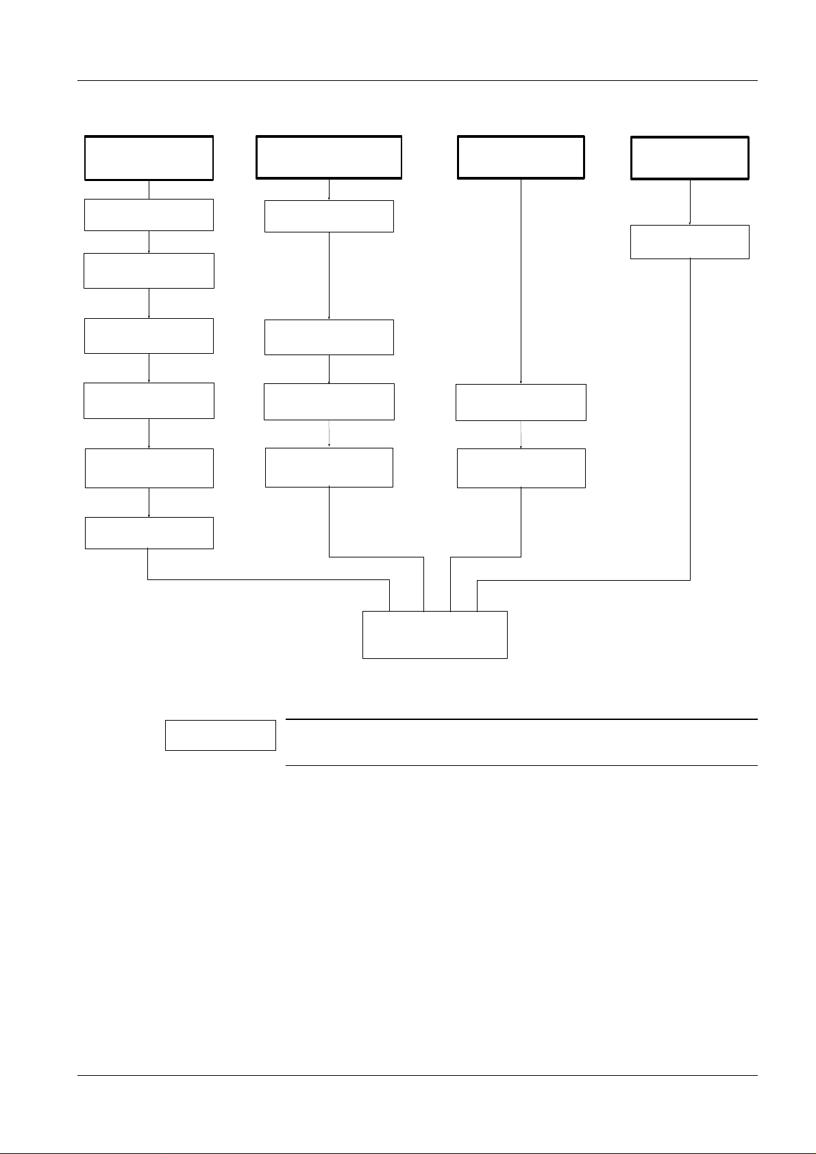
NOTICE
General 1
1 - 1
I.I. replacement
Parallelism check
Determining
the electrical I.I. center
Centering the tube - I.I.
Adjustment of Isocenter
30° position
Adjustment of Isocenter
- 10° position
Cross hairs adjustment
Parallelism check
Centering the tube - I.I.
Adjustment of Isocenter
30° position
Adjustment of Isocenter
- 10° position
Shock wave head replacementTube - Collimator replacement
Adjustment of Isocenter
30° position
Adjustment of Isocenter
- 10° position
Camera replacement
Image orientation check
Final steps
These instructions describe all centering procedures. Perform only the
adjustments necessary for the system you are servicing.
Tools and auxiliary devices required 1
• Standard installation tools
• Water level
• M6 washer (hole diameter 6 - 6.5 mm)
Siemens AG Register RXL2-120.071.01 Page 1 of 2 LITHOSTAR Multiline
Medical Engineering Rev. 04 05.97 TD SP 1
Page 6

1 - 2 General
This page intentionally left blank.
LITHOSTAR Multiline Register RXL2-120.071.01 Page 2 of 2 Siemens AG
Rev. 04 05.97 TD SP 1 Medical Engineering
Page 7

Centering the X-ray tube / Image intensifier 2
2 - 1
4
3
1
1
Fig. 1
2
Parallelism check 2
• Remove the covers of the shock wave head.
• Mount the short table extensio n to the left side of the table.
• Move the C-arm into the 0° position.
• Remove the I.I. collision protect ion.
- Insert the jumper at X18 or make a connection using a wire.
When replacing the X-ray tube:
• Prior to mounting the collimator t o the machined flange surface (3/Fig.1) , pl ace a
protractor spirit level on the fl ange and check whether it is level.
• If necessary, adjust the posit ion.
Adjusting th e X-ray tube:
- Patient longitudinal direction4x screws (1/Fig. 1)
- Patient transverse direction Mounting ring screws (2/Fig. 1)
When replacing the I.I.:
• Check that the image intensifier is level.
Place a water level on the machined surfac e (4/Fig. 1) and adjust as follows:
Adjusting the I.I. parallelism:
- 23 cm I.I. Patient longitidunal direction
Patient transverse direction
- 33 cm I.I. Patient longitudinal direction
Patient transverse dir ection
screws (3/Fig . 2)
screws(4/Fig. 2)
screws (4/Fig. 4)
screws (3/Fig. 5 )
Siemens AG Register RXL2-120.071.01 Page 1 of 10 LITHOSTAR Multiline
Medical Engineering Rev. 01 05.97 TD SP 1
Page 8

2 - 2 Centering the X-ray tube / Image intensifier
Determining the electrical I. I. center 2
• Attach a washer to the center of the I.I. input. (Remove the grid; the plat e with the center
cross may remain attached.)
• Attach a transparent piece of tape in th e center of the monitor.
• Select the smallest zoom format.
• Release fluoro.
• Mark the image of the washer on the adhesive tape .
• Select full form at.
• Release fluoro.
The washer must appear centered on the marking (s mallest format on the adhesive
tape).
• If necessary, shift the washer on the I.I. input and repeat the entir e procedure, until the
"electrical center" is dete rmined.
(tolerance ± 1 mm)
.
LITHOSTAR Multiline Register RXL2-120.071.01 Page 2 of 10 Siemens AG
Rev. 01 05.97 TD SP 1 Medical Engineering
Page 9

Centering the X-ray tube / Image intensifier 2 - 3
3
2
1
2
4
Fig. 2 Fig. 3
Adjusting the 23 cm I.I. 2
1
Parallel adjustment in the patient longitudinal direction 2
• Remove the 9 screws (1/Fig. 2) .
• The image intensifier can be shifted in the patient longitudinal direction by loosening or
tightening the 4 screws (2/Fig. 1) .
Parallel adjustment in the patient transverse direction 2
• Turning the screw (1/Fig. 3) shift s the I.I. in the patient transv erse direction.
• Retighten the 9 screws (1/Fig. 2) .
• Close the collimator.
• Release fluoro and check whether the radi ation field appears to be centered to the
marking on the image intensifier (washer or ce nter cross).
If not, proceed as foll ows:
• Remove the lower rubber panelling with a 2.5mm Allen key (2 scr ews).
• Loosen the two screws on the inside with a 3mm Allen key.
• Remove the panelling from the top of the C-a rm (4 panelling screws with 2.5mm Allen
key)
• Loosen the two screws with a 6mm Allen key, but do not remove them.
The rubber panelling can now be removed towards t he top.
• Reinstall the rubber panelling i n the reverse order.
Siemens AG Register RXL2-120.071.01 Page 3 of 10 LITHOSTAR Multiline
Medical Engineering Rev. 01 05.97 TD SP 1
Page 10

2 - 4 Centering the X-ray tube / Image intensifier
3
1
4
4
2
2
1
Fig. 4 Fig. 5
Adjusting the 33 cm I.I. 2
Removing the I.I. mounting cover s 2
• Loosen the set screws on the U-latch and remove t hem from the top.
• Loosen only the 6 cover screws (white) ; do not remove them.
• Loosen the 4 cover clamps and remove the cover.
• Loosen only the two upper and four lower whit e cover screws; do not remove them. Pull
the cover off toward the back.
• Reinstall the covers in the rev erse order.
Parallel adjustment in the patient longitudinal direction 2
• Remove the five Allen screws (1/F ig. 4) (Only 3 screws are pict ured).
• The I.I. (2/Fig. 4) can be shif ted with the screws in the patient longitudinal direction .
• Retighten the five Allen screws (1/F ig. 4).
3
Parallel adjustment in the patient transverse direction 2
• Remove the 7 screws (1/Fig. 5) on each side.
• The I.I. can be shifted with the s crew (2/Fig. 5) in the patient transverse direction.
• Retighten the screws (1/Fig. 5).
LITHOSTAR Multiline Register RXL2-120.071.01 Page 4 of 10 Siemens AG
Rev. 01 05.97 TD SP 1 Medical Engineering
Page 11

Centering the X-ray tube / Image intensifier 2 - 5
Adjustment of the isocenter, +30°/-10° position 2
a)
Fig. 6 Fig. 7
b)
Adjustment of the isocenter, +30° position 2
• Move the shock wave head into the coupling position (not to be confused with the gel
position).
• Attach the adjustment device.
• Move the C-arm into the 30° position.
• Release fluoro.
The adjustment ball must be located in the cent er of the indicator or the cross hai rs (refer
to Fig. 10)
a) Shifting in the longitudinal patient direction
• Loosen the mounting screws (B/Fig. 7) for t he shock wave head.
• Shift the shock wave head in the long itudinal patient direction un til the ball lies within th e
marking (indicator, centering cr oss-hairs) with fluoro.
- moving the ball in the monitor image YZ
- moving the shock wave head in the unit yz
(For the directions in dicated, the short tabl e extension must be attached to t he left side of
the table. Otherwise the figure is di splayed laterally rever sed.
In addition, prone position must not be selected).
• Retighten the mounting screws.
b) Shifting in the transverse patient direction
• Connect the service PC to MULTILINE.
• Connect the DVM to measurement points D5.X12 and D5.X30 (0V).
• Check the value at X12 (pot value R3 for W driv e); it should be 4.77 V ± 5 mV.
• Go into the ”uncontrolled mode” as descri bed in the chapter ”System Logon, Adjustment
Calibration” of the operating i nstructions for service sof tware (RXL2-120.113.01...).
Siemens AG Register RXL2-120.071.01 Page 5 of 10 LITHOSTAR Multiline
Medical Engineering Rev. 01 05.97 TD SP 1
Page 12

2 - 6 Centering the X-ray tube / Image intensifier
CAUTION
CAUTION
Fig. 8
The system is in the ”uncontrolled mode”. This means that the program
no longer monitors system movements. Avoid points of collision.
• Switch on fluoro. Move the ball into t he center of the indicator or the cross -hairs ) via the
tableside control. Use the keys for t he W drive.
• Change from the ”uncontrolled mode” to the st andard operating mode.
Perform a reset at Host D1 each time you set the R3 value.
• Loosen the set screws (M/Fig. 8) of potenti ometer R3 (1.5mm Allen key required) and
rotate the potentiometer, until the nomin al value of 4.77 V ± 5 mV is attained on the DVM.
(ADC value 954 ± 4 on the service PC
• Retighten the screws .
• Readjust reference switch S3:
- the switch must be closed in the range between 4.75V and 4.79V,
(ADC value 954 ± 4 )
- the switch must be open in the range between <4.73 V (ADC value > 946) and > 4. 81 V
(ADC value > 962).
LITHOSTAR Multiline Register RXL2-120.071.01 Page 6 of 10 Siemens AG
Rev. 01 05.97 TD SP 1 Medical Engineering
Page 13

Centering the X-ray tube / Image intensifier 2 - 7
Fig. 9
Adjustment of the isocenter, -10° position 2
• Move the tube into the -10° position.
• Switch on fluoro.
The adjustment ball must be located in the cent er of the indicator or the cross hai rs. If
required, adjust it.
• Loosen the three mounting screws (S/Fig. 9) at the shock wave head.
• Loosen the set screws (M) at the eccentri c adjustment (E) (Fig. 9).
• Move the ball into the center of the i ndicator or cross hairs by pushing t he excentric
screws on the shock wave head.
Do not move the shock wave head out of alignment.
• Retighten the shock wave head mounting screws (S/ M Fig. 9) .
• Switch on fluoro. Alternately select the +30° and -10° position and verity that the ball is
displayed in the isocenter.
• If necessary, repeat the adjust ment of the isocenter until there i s no more drifting.
• If a washer was attached for centeri ng, remove it.
• Remove the adjustment device.
• Move the W drive back into the coupling position.
• Remount the adjustment device.
• Check the isocenter adjustment in bot h the +30° and -10° positions with fluoro ON.
If necessary, repeat the isocent er adjustment.
• Remove the adjustment device (doe s not apply to replacement of the I .I.)
• Perform the cross hairs adjustment or final steps.
Siemens AG Register RXL2-120.071.01 Page 7 of 10 LITHOSTAR Multiline
Medical Engineering Rev. 01 05.97 TD SP 1
Page 14

2 - 8 Centering the X-ray tube / Image intensifier
CAUTION
Cross hairs adjustment 2
The shock wave head is in the coupling position (not to be confused with the GEL position).
• Switch fluoro on and check the isocent er at -30° and -10°.
Correction
needed
Fig. 10
ok
Acceptable
• If the cross hairs need to be adjusted, t he I.I. collision protection an d the grid cover ring
on the I.I. must be removed.
The grid is attached by means of this cover and must also be removed.
• Bypass jumper X18, so that the safety ci rcuit is activated.
• Loosen the screws in the retai ner ring far enough so that the cross hairs can be adjusted.
• Switch fluoro on and move the centering cross hai rs until the ball of the adjustment
device is displayed in the center of t he marking in both projection planes (-30° and -10°).
• Tighten the cross hairs mounti ng screws. Ensure that the retainer ri ng does not bend.
• Insert the I.I. grid at an an gle of 45° ( ± 10°) between the bolts of the r etainer ring.
• Reinstall the I.I. colli sion protection and tighten the grid cover ring on the I.I. from below
to secure the grid and to prevent twi sting.
Image orientation check 2
• Close one of the collimator pairs completel y.
• Open the other collimator pair complet ely.
• Release fluoro.
• Check whether the image orientation is ver tical or horizontal on the monitor.
• To adjust, loosen the mounting screws on the camer a and turn the camera head.
• Check the image orientation again with FL .
LITHOSTAR Multiline Register RXL2-120.071.01 Page 8 of 10 Siemens AG
Rev. 01 05.97 TD SP 1 Medical Engineering
Page 15

Centering the X-ray tube / Image intensifier 2 - 9
Final steps 2
• Remove jumpers at plug X18 .
• Reinstall the I.I. colli sion protection.
• Reinstall the shock wave head cover.
• Measure the protective conductor function.
• Perform an IQ test according to cha pter 6 "Dose rate" of the Start-up Inst ructions (does
not apply when replacing the shock wave head).
• Replace or supplement the documents.
• Check all functions.
Siemens AG Register RXL2-120.071.01 Page 9 of 10 LITHOSTAR Multiline
Medical Engineering Rev. 01 05.97 TD SP 1
Page 16

2 - 10 Centering the X-ray tube / Image intensifier
This page intentionally left blank.
LITHOSTAR Multiline Register RXL2-120.071.01 Page 10 of 10 Siemens AG
Rev. 01 05.97 TD SP 1 Medical Engineering
Page 17

Changes as compared to previous versions 3
Templat es changed
Chapter 0 Revision lev el and table of contents adjusted
Chapter 1 Text changes
Chapter 2 New
Chapter 3 New
3 - 1
TD SP 1 / Schlee
TD SP 2 / Wendt
SMS Iselin
Siemens AG Register RXL2-120.071.01 Page 1 of 2 LITHOSTAR Multiline
Medical Engineering Rev. 01 05.97 TD SP 1
Page 18

3 - 2 Changes as compared to previous versions
This page intentionally left blank.
LITHOSTAR Multiline Register RXL2-120.071.01 Page 2 of 2 Siemens AG
Rev. 01 05.97 TD SP 1 Medical Engineering
 Loading...