

Page 1
LITHOSTAR Multiline
Planning Guide
System
SP
© Siemens AG 1994
The reproduction, transmission or
use of this document or its contents
is not permitted without express
written authority. Offenders will be
liable for damages. All rights,
including rights created by patent
grant or registration of a utility
model _or_ design,_are_ reserved.
English
Print No.: RXL2-120.021.01.12.02 Doc. Gen. Date: 10.04
Replaces: RXL2-120.021.01.11.02
Page 2

0 - 2 Revision
Chapter Page Revision
all all 01
all all 02
all all 03
all all 04
all all 05
all all 06
all all 07
all all 08
all all 09
all all 10
all all 11
all all 12
Document revision level
The document corresponds to the version/revision level effective at the time of system delivery.
Revisions to hardcopy documentation are not automatically distributed.
Please contact your local Siemens office to order current revision levels.
Disclaimer
The installation and service of equipment described herein is to be performed by qualified personnel
who are employed by Siemens or one of its affiliates or who are otherwise authorized by Siemens or
one of its affiliates to provide such services.
Assemblers and other persons who are not employed by or otherwise directly affiliated with or authorized by Siemens or one of its affiliates are directed to contact one of the local offices of Siemens or
one of its affiliates before attempting installation or service procedures.
LITHOSTAR Multiline RXL2-120.021.01 Page 2 of 4 Siemens AG
Rev. 12 10.04 CS SD 21 Medical Solutions
Page 3

Contents 0 - 3
Page
1 _______General Notes _________________________________________________ 1 - 1
General notes . . . . . . . . . . . . . . . . . . . . . . . . . . . . . . . . . . . . . . 1 - 1
Safety . . . . . . . . . . . . . . . . . . . . . . . . . . . . . . . . . . . . . . . . . . 1 - 2
System Configuration . . . . . . . . . . . . . . . . . . . . . . . . . . . . . . . . . . 1 - 3
(Basic layout), LITHOSTAR Multiline with POLYDOROS LX . . . . . . . . . . . . 1 - 3
2 _______Room Planning ________________________________________________ 2 - 1
Wall Distances and Room Height, Version I. . . . . . . . . . . . . . . . . . . . . . . 2 - 1
Wall Distances and Room Height, Version II . . . . . . . . . . . . . . . . . . . . . . 2 - 2
Dimensions: LITHOSTAR Multiline . . . . . . . . . . . . . . . . . . . . . . . . . . . 2 - 3
Dimensions: UMR Cabinets with POLYDOROS LX . . . . . . . . . . . . . . . . . . 2 - 4
Dimensions: UMR Cabinets with POLYDOROS SX . . . . . . . . . . . . . . . . . . 2 - 5
Dimensions: System Operating Console . . . . . . . . . . . . . . . . . . . . . . . . 2 - 6
Dimensions: Monitor Trolley, Option. . . . . . . . . . . . . . . . . . . . . . . . . . . 2 - 7
Dimensions: Respiratory ECG Gating, Option . . . . . . . . . . . . . . . . . . . . . 2 - 7
Dimensions: Ultrasound System with Monitor, Option . . . . . . . . . . . . . . . . . 2 - 8
Laser Camera Connection, Option . . . . . . . . . . . . . . . . . . . . . . . . . . . 2 - 8
Static Load Prerequisites . . . . . . . . . . . . . . . . . . . . . . . . . . . . . . . . 2 - 9
Suggested Construction for Radiation Protection Shield . . . . . . . . . . . . . . . 2 - 10
3 _______Preparation for Installation _______________________________________ 3 - 1
Installation Information . . . . . . . . . . . . . . . . . . . . . . . . . . . . . . . . . 3 - 1
Dimensions: Installation Plate . . . . . . . . . . . . . . . . . . . . . . . . . . . . . 3 - 2
Installation Plate . . . . . . . . . . . . . . . . . . . . . . . . . . . . . . . . . . . . . 3 - 3
Water Installation . . . . . . . . . . . . . . . . . . . . . . . . . . . . . . . . . . . . 3 - 4
On-site Electrical Installation . . . . . . . . . . . . . . . . . . . . . . . . . . . . . . 3 - 5
4 _______System Connections____________________________________________ 4 - 1
Overview of Connections . . . . . . . . . . . . . . . . . . . . . . . . . . . . . . . . 4 - 1
5 _______Technical Data _________________________________________________ 5 - 1
Electrical Data . . . . . . . . . . . . . . . . . . . . . . . . . . . . . . . . . . . . . 5 - 1
Weights and Heat Dissipation . . . . . . . . . . . . . . . . . . . . . . . . . . . . . 5 - 1
Environmental Conditions . . . . . . . . . . . . . . . . . . . . . . . . . . . . . . . 5 - 2
Packing and Transportation . . . . . . . . . . . . . . . . . . . . . . . . . . . . . . . 5 - 2
Surface Colors . . . . . . . . . . . . . . . . . . . . . . . . . . . . . . . . . . . . . 5 - 2
Additional Data . . . . . . . . . . . . . . . . . . . . . . . . . . . . . . . . . . . . . 5 - 2
Noise Level . . . . . . . . . . . . . . . . . . . . . . . . . . . . . . . . . . . . . . .5 - 3
6 _______Transportation Specifications ____________________________________ 6 - 1
Transport Dimensions, Basic System with Transport Frame . . . . . . . . . . . . . . 6 - 1
Siemens AG RXL2-120.021.01 Page 3 of 4 LITHOSTAR Multiline
Medical Solutions Rev. 12 10.04 CS SD 21
Page 4

0 - 4 Contents
Page
7 ______ Changes to Previous Version _____________________________________ 7 - 1
LITHOSTAR Multiline RXL2-120.021.01 Page 4 of 4 Siemens AG
Rev. 12 10.04 CS SD 21 Medical Solutions
Page 5

General Notes 1
1 - 1
General notes 1
- With distribution of these revision level, all preceding planning guides, Speed - Infos (PG’s) and
drafts lose their validity.
- All layouts issued by the Planning Departments must bear a note referring to the installation and
delivery conditions of Siemens Medical Engineering. The installation and delivery conditions must
be submitted with the layouts.
- Unless otherwise specified, all dimensions are indicated in "mm".
- The symbol indicates a change (see revision status).
- Orientation points
Points specific to system components to which reference is made when positioning system
components to each other or in the room.
The isocenter of a radiographic system is always illustrated as the orientation point.
-Fixpoints
Clearly marked points on system components, installation ceiling, walls or floor on which cable
outlets are located.
Illustration in the drawings: octagon with letter/number-combination.
The cable lengths specify the maximum fixpoint distances and thus the maximum distances
between the individual system components.
- Room height
The room height is the distance measured from the top surface of the floor to the bottom surface of
the ceiling structural elements (Unistrut rails) (bottom surface of drop ceiling).
- Room lighting
According to DIN 68 68-57 (international standard in preparation), the lighting in rooms in which
image playback devices (monitors) are used for diagnosis, the following requirements must be
met:
adjustable, no anti-glare screen, reproducible adjustment of the lighting (e. g. dimmer with
scala),
no glare or reflection from windows, lights and light boxes in the standard working position of
the monitors.
Hotline + 49 (9191) 18 - 8080
Siemens AG RXL2-120.021.01 Page 1 of 4 LITHOSTAR Multiline
Medical Solutions Rev. 12 10.04 CS SD 21
Page 6

1 - 2 General Notes
Safety 1
- The provisions of the relevant fire safety regulations must be observed for the premises.
- The system has been developed according to EN 60601 - 1.
- Minimum dimensions (e. g. room heights, safety distances) indicated in the planning guides are
marked "min."
- Basic strength against electromagnetic sources of interference.
Result of lightning discharges.
The protection targets of the different lightning protection areas up to the unit connection are also
specified in the IEC 1024, DIN 48810, VDE 0675 and in the DEMVT recommendations.
LITHOSTAR Multiline RXL2-120.021.01 Page 2 of 4 Siemens AG
Rev. 12 10.04 CS SD 21 Medical Solutions
Page 7
General Notes 1 - 3
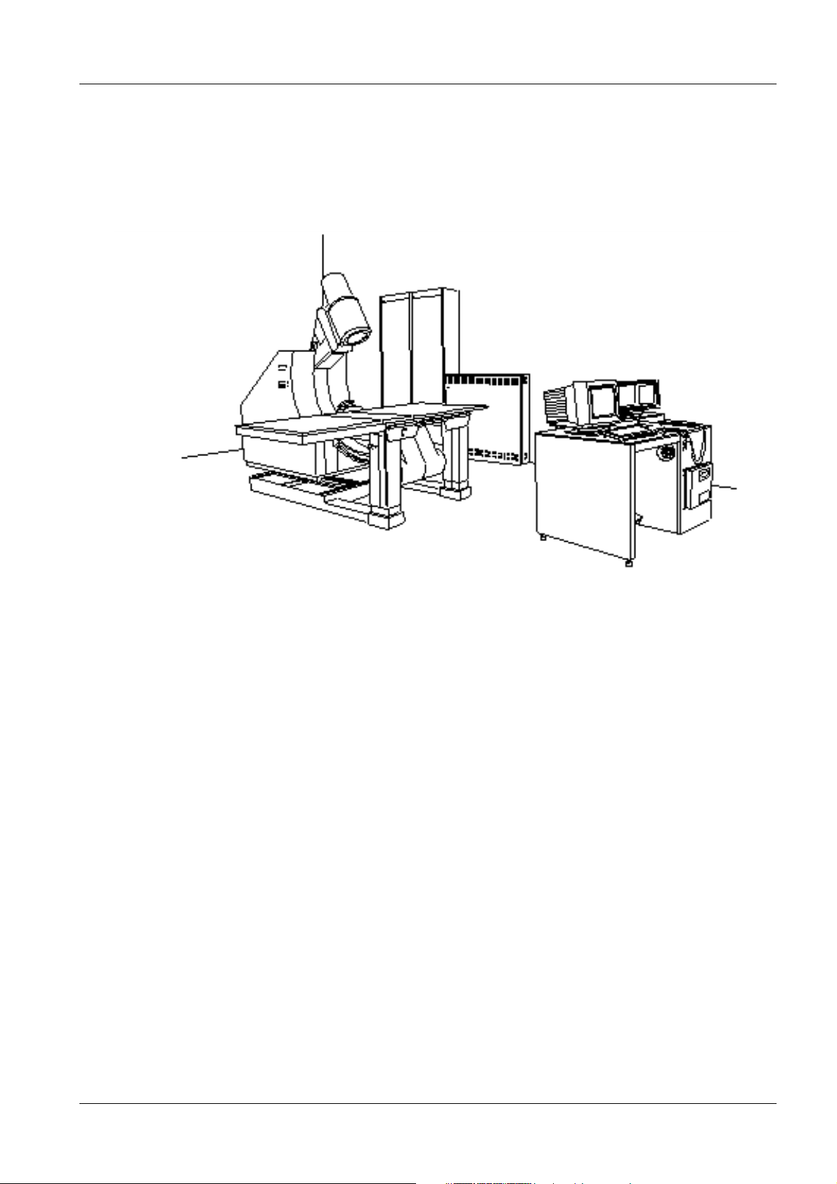
System Configuration 1
(Basic layout), LITHOSTAR Multiline with POLYDOROS LX 1
The following options are not shown in the basic layout: Respiratory ECG triggering
Ultrasound unit
Monitor cart
Diamentor
DICOM
Siemens AG RXL2-120.021.01 Page 3 of 4 LITHOSTAR Multiline
Medical Solutions Rev. 12 10.04 CS SD 21
Page 8

1 - 4 General Notes
This page intentionally left blank.
LITHOSTAR Multiline RXL2-120.021.01 Page 4 of 4 Siemens AG
Rev. 12 10.04 CS SD 21 Medical Solutions
Page 9
Room Planning 2
2 - 1
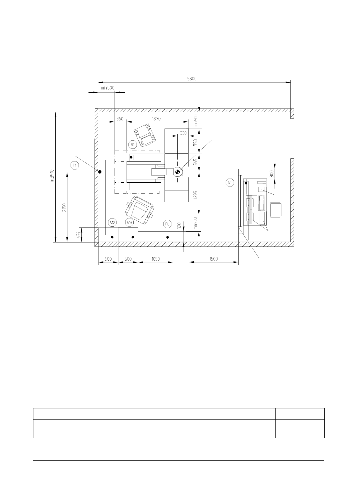
Wall Distances and Room Height, Version I 2
LITHOSTAR Multiline with POLYDOROS LX
*1
*5
*2
*1
*4
Orientation point
*3
*6
*5
*1
*7
Radiation protection
shield, on-site
1 : 50
*1 Safety distance according to the equipment safety law
*2 System excursion
*3 Only in countries with UL regulations apply
*4 Option: Ultrasound unit
*5 Option: 3rd monitor with monitor trolley
Cable feed max. 5 cm above floor.
Cable outlet, item no. 14 76 241 R 4189 also required
*6 Option: Diamentor
*7 Option: DICOM
Room size
Area Length Width Height
Technically possible minimum
examination room size
Siemens AG RXL2-120.021.01 Page 1 of 10 LITHOSTAR Multiline
Medical Solutions Rev. 12 10.04 CS SD 21
22.70 m
2
5.80 m 3.90 m min. 2.40 m
Page 10
2 - 2 Room Planning
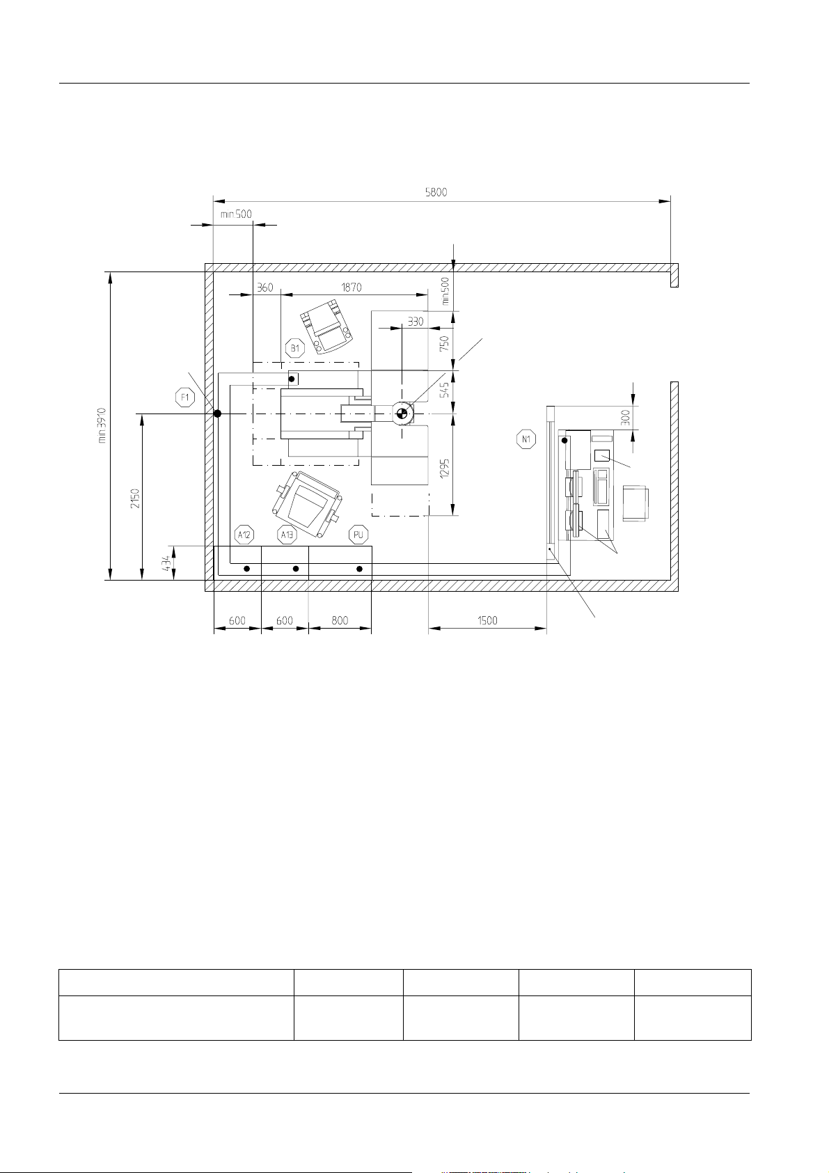
Wall Distances and Room Height, Version II 2
LITHOSTAR Multiline with POLYDOROS SX
*1
*3
*2
*3
*5
*1
Orientation point
*4
*6
*7
Radiation protection
shield, on-site
1 : 50
*1 Safety distance according to the equipment safety law
*2 System excursion
*3 3rd monitor with monitor trolley
Cable feed max. 5 cm above floor.
Cable outlet, item no. 14 76 241 R 4189 also required
*4 Only in countries with UL regulations apply
*5 Option: Ultrasound unit
*6 Option: Diamentor
*7 Option: DICOM
Room size
Area Length Width Height
Technically possible minimum
examination room size
LITHOSTAR Multiline RXL2-120.021.01 Page 2 of 10 Siemens AG
Rev. 12 10.04 CS SD 21 Medical Solutions
22.70 m
2
5.80 m 3.90 m min. 2.40 m
Page 11
Room Planning 2 - 3
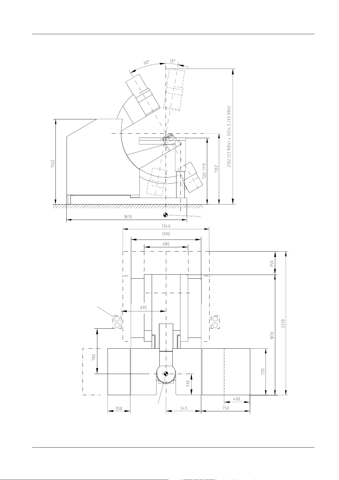
Dimensions: LITHOSTAR Multiline 2
Side view
Drawing shows the installation
plate embedded in the floor
Top vi e w
*1 System travel range
*2 Tabletop extension
right or left
Option:
preferred position:
water connection kit
*1
Orientation point
*1
*1
*2
Siemens AG RXL2-120.021.01 Page 3 of 10 LITHOSTAR Multiline
Medical Solutions Rev. 12 10.04 CS SD 21
Orientation
point
*2
1 : 25
Page 12

2 - 4 Room Planning
Dimensions: UMR Cabinets with POLYDOROS LX 2
POLYDOROS LX
Shock wave
cabinet
Control cabinet
1 : 20
NOTICE
LITHOSTAR Multiline RXL2-120.021.01 Page 4 of 10 Siemens AG
Rev. 12 10.04 CS SD 21 Medical Solutions
For improved visual effect, the front panels of the cabinets can be aligned
with one another.
Page 13

Room Planning 2 - 5
Dimensions: UMR Cabinets with POLYDOROS SX 2
POLYDOROS SX
Shock wave
cabinet
Control cabinet
1 : 20
Siemens AG RXL2-120.021.01 Page 5 of 10 LITHOSTAR Multiline
Medical Solutions Rev. 12 10.04 CS SD 21
Page 14

2 - 6 Room Planning
Dimensions: System Operating Console 2
*2
System
ON/OFF
E. STOP
Connection for footswitch (optional) 60 mm above the
floor (note adjustment range) and 500 mm from the front
Alternate
cable outlet
Operating keyboard for
option: DICOM
Door, system control console
Cable outlet ∅ 100 mm
Push-button pad
permanently installed
Operating
keyboard
1 : 20
Option: MULTISPOT
*1
LITHOSTAR Multiline RXL2-120.021.01 Page 6 of 10 Siemens AG
Rev. 12 10.04 CS SD 21 Medical Solutions
*1 Face plate is removed when installing the
MULTISPOT
Option: DICOM
*2 Display only at option DICOM available
Page 15

Room Planning 2 - 7
Dimensions: Monitor Trolley, Option 2
Dimensions of monitor trolley with 44 cm monitor (for Uro Plus equipment, included in delivery)
Swivel range
+ 15
o
... - 10
o
Radiation
indicator
Radiation indicator
Cable holder
both front
castors
with brakes
both rear castors
without brakes
Dimensions: Respiratory ECG Gating, Option 2
Patients monitor
A location for installation of the patients monitor must
be provided on-site.
Refer also to the accessory catalog for patient
monitoring
Siemens AG RXL2-120.021.01 Page 7 of 10 LITHOSTAR Multiline
Medical Solutions Rev. 12 10.04 CS SD 21
Page 16

2 - 8 Room Planning
Dimensions: Ultrasound System with Monitor, Option 2
1 : 20
The ultrasound option can be disconnected from device B1. A support bracket must be provided onsite for the excess corrugated tubing (6m).
Laser Camera Connection, Option 2
The optical video separation device between the laser camera and the Memoskop is installed in the
control cabinet. The cable from the optical video separation device to the laser camera must not
exceed a maximum length of 24 m.
LITHOSTAR Multiline RXL2-120.021.01 Page 8 of 10 Siemens AG
Rev. 12 10.04 CS SD 21 Medical Solutions
Page 17

Room Planning 2 - 9
Static Load Prerequisites 2
Orientation point
Cable outlet
Free area for levelling concrete
1 : 20
The pull forces that occur at the floor mounting points A are max. 1688 N per mounting point.
Total weight:
System
Floor plate
Patient
approx. 660 kg
approx. 130 kg
approx. 150 kg
∑ approx. 940 kg
• = Alternate bore
Siemens AG RXL2-120.021.01 Page 9 of 10 LITHOSTAR Multiline
Medical Solutions Rev. 12 10.04 CS SD 21
Page 18

2 - 10 Room Planning
Suggested Construction for Radiation Protection Shield 2
NOTICE
Variable side beams
depending on ceiling
height
Type Kyowa H 35 = 1.5 Pb at 110 kV can be used for the radiation protection
shield.
1 : 25
LITHOSTAR Multiline RXL2-120.021.01 Page 10 of 10 Siemens AG
Rev. 12 10.04 CS SD 21 Medical Solutions
Page 19

Preparation for Installation 3
3 - 1
Installation Information 3
The installation plate must be ordered in advance under item no. 31 27 052 J 1042.
Liebig expansion bolts/anchors, type LSP I 14/80 item no. 70 54 828 F 1107 and corresponding installation material are included in the shipment for the installation. Only the Liebig expansion bolts packed
with the unit may be used.
The system must be installed on a solid sub-floor with sufficient load-bearing capacity, such as concrete. If the existing self-leveling grout has sufficient load bearing capacity, the system can be installed
directly on the self-leveling grout.
Other types of floors and floor coverings without sufficient load bearing capacity should be removed
prior to the installation.
If the system is not being delivered by a third party (contractor, outside of Europe/overseas),
the transport roller set (identical to POLYSTAR) item no. 11 53 654 G 5338 must be ordered
in advance.
The UMR cabinets must be installed at the same level as the system.
After the installation, the space between the system and the floor must be sealed.
(Refer to installation instructions RXL2-120.031.01...)
NOTICE
NOTICE
NOTICE
The UMR cabinets should be planned left to right.
Generator - Shock wave cabinet - Control cabinet or
Control cabinet - Shock wave cabinet - Generator
The installation plate must be levelled.
Maximum deviation over the longest dimension =1 mm/m
Recommendations from Liebig and the Installation instructions enclosed
for the dowels RXL2-120.038.01 must be strictly observed.
With 440/480 V, connect the patients monitor monitor before the building
system transformer.
NOTICE
Option:
1 Water connection kit Item no. 16 12 972 G 5354
Siemens AG RXL2-120.021.01 Page 1 of 6 LITHOSTAR Multiline
Medical Solutions Rev. 12 10.04 CS SD 21
For information on installing LITHOSTAR Multiline in mobile environments,
refer to PG RXL2-120.021.02.01...
Page 20

3 - 2 Preparation for Installation
Dimensions: Installation Plate 3
*1
*3
*1
*3
*2
*3
*3
*3
*1
Orientation point
*1
*2
*1
*2
t = 12
*1
*1
*1
*2
1 : 10
*1 Alternate bore *2 System base mounting M10 *3 System mounting M8
LITHOSTAR Multiline RXL2-120.021.01 Page 2 of 6 Siemens AG
Rev. 12 10.04 CS SD 21 Medical Solutions
Page 21

Preparation for Installation 3 - 3
Installation Plate 3
Solid concrete
Insulation plates 2.0 mm
Installation plate
System
Concrete
Direct installation on self-leveling grout
Screed
Liebig expansion bolt*1
System
Levelling concrete
Insulating plates 2.0 mm
Concrete
Installation
plate
Self-leveling grout
*1 The instructions from the Liebig company must be observed.
Anchoring in the levelling concrete is not permitted.
Comply with the Installation Instructions RXL2-120.038.01.
Siemens AG RXL2-120.021.01 Page 3 of 6 LITHOSTAR Multiline
Medical Solutions Rev. 12 10.04 CS SD 21
Page 22

3 - 4 Preparation for Installation
Water Installation 3
Cover plate
Sealing with
sanitary silicone
Screed
Use caution due to
static forces when
cutting out self-leveling grout and
concrete
Shutoff valve
Flush with finished
floor
*1
*1 On-site water connection 1/2" external thread
System-front
Floor recess
(flush with top edge of finished floor)
Water installation
materials:
16 12 972 G 5354
(complete material
from on-site pipe)
1 : 2.5
on-site drain 1" external thread
NOTICE
LITHOSTAR Multiline RXL2-120.021.01 Page 4 of 6 Siemens AG
Rev. 12 10.04 CS SD 21 Medical Solutions
Prevent introduction of foreign substances into the drinking water supply.
Observe all national and local laws and regulations.
Page 23

Preparation for Installation 3 - 5
On-site Electrical Installation 3
Proposal for on-site power distribution per DIN VDE 0100-710 or national regulations
Power supply line
must be provided on-site
*1
*1 The fuse protection must
be selected to match the
generator used
Generator cabinet
SIEMENS
must be provided on-site
On/Off button with pilot lamp
Emergency shutdown button with lock
Generator cabinet
Power connection box
Patients monitor (optional)
Ultraschallgerät (optional)
1 To extraneous conductive parts
2 Per DIN EN 50178 Classification VDE 0160, "Equipping of high voltage systems with electronic
operating elements", the following FI switches must be used exclusively:
For U(N) = 3 ~ 400/415 V: I(N) = 63A, IdN = 30 mA for AC and pulsed as well as smooth DC currents.
Order from wholesale electrical supply company, Order No.FI 5SZ3 466 0KG05 all-current sensitive
Order from SPH2, Part No. 49 54 470 Y7933
(Width of the FI switch is 144 mm = 8TE, install on standard rail)
For countries in which this standard does not apply, the following ground fault interrupters can be
used for voltages of
> 415 V: With U(N) > 3 ~ 415 V; I(N) = 125 A, IdN = 30 mA
Doepke-Norden (order from SPH2, Part No. 51 41 168 Y7933)
2a Ground fault current interrupter (GF I) IDN 30 mA
3 Unit breaker
4 Option: Radiation display (24 V/5 W)
Siemens AG RXL2-120.021.01 Page 5 of 6 LITHOSTAR Multiline
Medical Solutions Rev. 12 10.04 CS SD 21
Page 24

3 - 6 Preparation for Installation
5 Applicable only in countries with line voltage of 115 V, ±10%, 50/60 Hz, ±1 Hz:
If the ultrasound option is configured, at least one power outlet with the specifications 115 V, ± 10%,
50/60 Hz, ±1 Hz must be installed on site, in the vicinity of the ultrasound unit. Depending on how
the room is set up, additional power outlets must be provided for the various working positions.
[ ] Numbers are free lead ends in m
LITHOSTAR Multiline RXL2-120.021.01 Page 6 of 6 Siemens AG
Rev. 12 10.04 CS SD 21 Medical Solutions
Page 25

System Connections 4
4 - 1
Overview of Connections 4
Option:
3rd Monitor
*3
System cabinet (Control
cabinet) I.I./TV
System
Option:
Ultrasound
unit
*2
*2
*1
*1
*1
*1
Generator and
System control panel
Option: Diamentor
Option: DICOM
Patients monitor
Shock wave cabinet
POLYDOROS SX
POLYDOROS LX
*1
Cable duct between the system and cabinets min. W 200 x H 50 mm.
Cable duct between the system control panel and cabinets min. W 50 x H 50 mm.
Tap holes of
*1 Zipper hose
If a conduit is used in place of a cable channel, a conduit with a dia. of at least 100 mm must be
provided for each zipper hose.
*2 The fiber optic cable and video cable are included in the Ultrasound option.
*3 Cable lengths = 18 m
NOTICE
∅ 80 mm must be provided for zipper hoses for ceiling feed-through.
∅ 50 mm
System cabling
The cable length between the system and each cabinet is 9 m.
The cable length from the control console to the control cabinet is 9 m.
The cable lengths indicated are fixed lengths that cannot be changed. If the
cable length required is shorter, storage must be provided for the excess
cable length. (Excess cable lengths may not be stored in the cabinets due
to EMC).
Siemens AG RXL2-120.021.01 Page 1 of 2 LITHOSTAR Multiline
Medical Solutions Rev. 12 10.04 CS SD 21
Page 26

4 - 2 System Connections
Options:
The cable length for patients monitor is 18 m.
The ultrasound unit can be disconnected from the system at B1. A support bracket must be
provided on-site for the remaining corrugated tubing (6m).
The measuring cable for the Diamentor is pulled in from the unit to the system cabinet. If the Diamentor
option is configured, lay the measuring cable further to the control console.
Die Option DICOM wird nur innerhalb der Bodenplatte installiert. Es sind keine zusätzlichen Kabel zu
verlegen.
LITHOSTAR Multiline RXL2-120.021.01 Page 2 of 2 Siemens AG
Rev. 12 10.04 CS SD 21 Medical Solutions
Page 27

Technical Data 5
5 - 1
Electrical Data 5
Power consumption
Power connection
POLYDOROS LX 50
3/N/PE
50/60 Hz
Power connection
POLYDOROS SX 65/80
3/N/PE
50/60 Hz
*1 If this power supply is not available, an on-site system transformer is required.
∼ 400 V ± 10%
± 1 Hz *1
∼ 400 V ± 10%
± 1 Hz *1
NOTICE
Max. Ri at the output terminals
(including the line Ri).
(observe UL regulations)
Rating = line voltage x internal fuse x
Ri max. = 170 m Ω POLYDOROS LX, Ri max. = 170 m Ω POLYDOROS SX
Fluoroscopy
and lithotripsy
2.5 kVA 94 kVA
2.1/3.3 kVA 120/145 kVA
≤ 170 m Ω POLYDOROS LX, ≤ 170 m Ω POLYDOROS SX
Transient power con-
sumption during
radiography
√3 [kVA]
Internal fuse
35 A
slow-blow
50 A
slow-blow
Weights and Heat Dissipation 5
Weight [kg] Heat dissipation [W]
LITHOSTAR Multiline
System approx. 660 approx. 250
Control cabinet approx. 160 approx. 800
Shock wave cabinet approx. 240 approx. 600
System control console approx. 110 approx. 150
Generator cabinet LX approx. 230 approx. 300
Generator cabinet SX approx. 290 approx. 900
Monitor and monitor trolley approx. 100 approx. 90
Ultrasound system approx. 85 approx. 450
Patients monitor approx. 5 approx. 55
Physiological monitor approx. 11 approx. 50
Siemens AG RXL2-120.021.01 Page 1 of 4 LITHOSTAR Multiline
Medical Solutions Rev. 12 10.04 CS SD 21
Page 28

5 - 2 Technical Data
Environmental Conditions 5
LITHOSTAR Multiline
without Ultrasound option
Permissible ambient temperature + 10° C ... + 35° C- 20° C ... + 35° C
Permissible relative humidity 15 % ... 75 % 10 % ... 75 %
Barometric pressure 700 hPa - 1060 hPa 500 hPa - 1060 hPa
LITHOSTAR Multiline
with Ultrasound option
Permissible ambient temperature + 15
Permissible relative humidity 30 % ... 75 % 10 % ... 75 %
Barometric pressure 700 hPa - 1060 hPa 500 hPa - 1060 hPa
Operating Transport / Storage
Operating Transport / Storage
° C ... + 35° C- 10° C ... + 35° C
Packing and Transportation 5
Largest crate L 2400 x W 1240 x H 2000 mm
Heaviest individual part
approx.
approx.
970 kg with transport frame and palette
840 kg with transport frame, without packaging
minimum door width and door height
for transport
min.
approx.
min.
1100 mm door width
1800 mm corridor width
2000 mm door height
Surface Colors 5
Main color Medical White C610
Combination color Anthracite C614
Additional Data 5
POLYDOROS LX 50 refer to PG RX63-020.021.01...
POLYDOROS SX 65/80 refer to PG RX63-065.021.01...
Monitor trolleys (optional) refer to PG RX53-020.021.01...
Installation in mobile environments refer to PG RXL2-120.021.02...
LITHOSTAR Multiline RXL2-120.021.01 Page 2 of 4 Siemens AG
Rev. 12 10.04 CS SD 21 Medical Solutions
Page 29

Technical Data 5 - 3
Noise Level 5
Noise generation during shock wave release at 1 m distance from the patient’s head
Noise level [db (A)]
Energy level 4
Energy level 7
≤ 70.4
≤ 73.3
Siemens AG RXL2-120.021.01 Page 3 of 4 LITHOSTAR Multiline
Medical Solutions Rev. 12 10.04 CS SD 21
Page 30

5 - 4 Technical Data
This page intentionally left blank.
LITHOSTAR Multiline RXL2-120.021.01 Page 4 of 4 Siemens AG
Rev. 12 10.04 CS SD 21 Medical Solutions
Page 31

Transportation Specifications 6
6 - 1
Transport Dimensions, Basic System with Transport Frame 6
*1
*1
*1 Required for removal of the transport pallet
NOTICE
Siemens AG RXL2-120.021.01 Page 1 of 2 LITHOSTAR Multiline
Medical Solutions Rev. 12 10.04 CS SD 21
Minimum door width 1100 mm, minimum corridor width approx. 1800 mm,
minimum door height 2000 mm.
Transport height without transport rollers: 23 cm I.I.1860 mm
Transport height without transport rollers: 33 cm I.I. 1989 mm
Page 32

6 - 2 Transportation Specifications
This page intentionally left blank.
LITHOSTAR Multiline RXL2-120.021.01 Page 2 of 2 Siemens AG
Rev. 12 10.04 CS SD 21 Medical Solutions
Page 33

Changes to Previous Version 7
Chapter Page Change
0 - 7 Rev. level of document changed from 11 to 12.
2 2-7 SIRECUST by patients monitor replaces.
3 3-1 SIRECUST by patients monitor replaces.
3 3-5 Text updated.
4 4-1 and 4-2 SIRECUST by patients monitor replaces.
5 5-1 SIRECUST by patients monitor replaces.
5 5-2 Surface colors updated.
7 7-1 Changes to previous version updated.
7 - 1
Siemens AG RXL2-120.021.01 Page 1 of 2 LITHOSTAR Multiline
Medical Solutions Rev. 12 10.04 CS SD 21
Page 34

7 - 2 Changes to Previous Version
This page intentionally left blank.
LITHOSTAR Multiline RXL2-120.021.01 Page 2 of 2 Siemens AG
Rev. 12 10.04 CS SD 21 Medical Solutions
 Loading...