

Page 1

LITHOSTAR Multiline
System Descript ion
SP
© Siemens AG 1995
The reproduction, transmission or
use of this document or its contents
is not permitted without express
written authority. Offenders will be
liable for damages. All rights,
including rights created by patent
grant or registration of a utility
model _or_ design,_are_ reserved.
Register 7 English
Print No.: RXL2-120.041.01.03.02 Doc. Gen. Date: 09.97
Replaces: RXL2-120.041.01.02.02
Page 2

0 - 2 Revision
Chapter Page Revision
0 1 to 4 02
11 to 1202
2 1 to 8 02
3 1 to 6 02
4 1 to 4 02
51 to 1402
6 1 to 8 02
71 to 1802
8 1 to 4 02
9 1 to 4 02
10 1 to 10 02
11 1 to 2 01
LITHOSTAR Multiline Register 7 RXL2-120.041.01 Page 2 of 4 Siemens AG
Rev. 03 09.97 TD SD 34 Medical Engineering
Page 3

Contents 0 - 3
Page
1 _______System Overview________________________________________________1-1
General . . . . . . . . . . . . . . . . . . . . . . . . . . . . . . . . . . . . . . . . . 1-3
System components . . . . . . . . . . . . . . . . . . . . . . . . . . . . . . . . . . . 1-5
System controls . . . . . . . . . . . . . . . . . . . . . . . . . . . . . . . . . . . . . 1-9
Block diagram . . . . . . . . . . . . . . . . . . . . . . . . . . . . . . . . . . . . . .1-11
2 _______Control Panels__________________________________________________2-1
Operating PC . . . . . . . . . . . . . . . . . . . . . . . . . . . . . . . . . . . . . . 2-3
Main control panel and tableside control panel . . . . . . . . . . . . . . . . . . . . . 2-5
DUEP Interface . . . . . . . . . . . . . . . . . . . . . . . . . . . . . . . . . . . . . 2-7
3 _______System Startup _________________________________________________3-1
Simplified program sequence . . . . . . . . . . . . . . . . . . . . . . . . . . . . . . 3-3
4 _______Interf ace I/O signals ___________________________ __________________4-1
Overview . . . . . . . . . . . . . . . . . . . . . . . . . . . . . . . . . . . . . . . . 4-3
5 _______Motor Control___________________________________________________5-1
Overview . . . . . . . . . . . . . . . . . . . . . . . . . . . . . . . . . . . . . . . . 5-3
Important system positions . . . . . . . . . . . . . . . . . . . . . . . . . . . . . . . 5-7
Shock wave drive “W” . . . . . . . . . . . . . . . . . . . . . . . . . . . . . . . . . .5-11
Overview of the drives - Tables . . . . . . . . . . . . . . . . . . . . . . . . . . . . .5-12
Overview of the motors . . . . . . . . . . . . . . . . . . . . . . . . . . . . . . .5-12
Safety limit switches for the smaller drives . . . . . . . . . . . . . . . . . . . . .5-12
Safety limit switches for the larger drives . . . . . . . . . . . . . . . . . . . . . .5-12
6 _______Safety Circuit ___________________________________________________ 6-1
Safety circuit for larger drives . . . . . . . . . . . . . . . . . . . . . . . . . . . . . . 6-3
Safety circuit for smaller drives . . . . . . . . . . . . . . . . . . . . . . . . . . . . . 6-7
7 _______Shock Wave System _____________________________________________7-1
Interfaces N11 / N12 . . . . . . . . . . . . . . . . . . . . . . . . . . . . . . . . . . 7-3
Interface board W16. . . . . . . . . . . . . . . . . . . . . . . . . . . . . . . . . . . 7-5
Coupling control. . . . . . . . . . . . . . . . . . . . . . . . . . . . . . . . . . . . . 7-7
Cooling system . . . . . . . . . . . . . . . . . . . . . . . . . . . . . . . . . . . . .7-11
Overview of board W11 . . . . . . . . . . . . . . . . . . . . . . . . . . . . . . . . .7-13
Monitoring system. . . . . . . . . . . . . . . . . . . . . . . . . . . . . . . . . . . .7-17
Block wiring diagram . . . . . . . . . . . . . . . . . . . . . . . . . . . . . . . . . .7-19
Siemens AG Register 7 RXL2-120.041.01 Page 3 of 4 LITHOSTAR Multiline
Medical Engineering Rev. 03 09.97 TD SD 34
Page 4

0 - 4 Contents
Page
8 ______ Resp. and ECG Triggering ________________________________________8-1
ECG and respiratory triggering block diagram . . . . . . . . . . . . . . . . . . . . . . 8-3
9 ______ Generator Function Unit __________________________________________9-1
10 _____ Image Acquisition _________________ _____ _____ ____ _____ __________10-1
Overview . . . . . . . . . . . . . . . . . . . . . . . . . . . . . . . . . . . . . . . . 10-3
Fluoroscopy and Film acquisition. . . . . . . . . . . . . . . . . . . . . . . . . . . . 10-5
Snap shot (optional) . . . . . . . . . . . . . . . . . . . . . . . . . . . . . . . . . . 10-9
11 _____ Ultrasound function unit_________________________________________11-1
12 _____ Changes to previous version _____________________________________12-1
LITHOSTAR Multiline Register 7 RXL2-120.041.01 Page 4 of 4 Siemens AG
Rev. 03 09.97 TD SD 34 Medical Engineering
Page 5

System Overview 1
1 - 1
Document structure
Comments and
suggestions
The system description was generated according to the following criteria:
• Empirical values recorded from function descriptions of previous versions
The system description can always be improved since it is not necessarily
complete in all aspect s. T herefore, I hope there will be com m ents and su ggestions from the field. As far as possible, I shall try to incorporate any comments and suggestions into the document.
Please w rite to me wit h you r s uggestions for improvement. Many s uggestions, while th ey may app ear improb able at t he outset, ca n be the key to sudden "i ns ight" for a service engi neer.
Many thank s to all of you participating in the preliminary pha s e for your co m ments and suggested improvements.
.
Gunar Kneisl TDF 1
My addre s s is as follows :
Werner von Siemen s-Straße 43
91052 Erl an gen
or:
OPSBRD::Kneisl
E-Mail: gunar.kneisl@med.siemens.de
NOTICE
All voltages in the document are typical values and are
not intended to be used for adjustments.
Always use the cu r re n t M ai n tenance I n str u ctions for
any ad justments requ i red.
Siemens AG Register 7 RXL2-120.041.01 Page 1 of 12 LITHOSTAR Multiline
Medical Engineering Rev. 03 09.97 TD SD 34
Page 6
1 - 2 System Overview
SC
3rd monitor (option)
PC
Monitor
Monitor I + II
SIRECUST
(option)
Respiratory / ECG
Moni to r (o p tion
System-
control-
console
Multispot
(option)
Polydoros
LX
)
AC
Polydoros
SX
Charg-
ing unit
”HPE”
N12
Shock-
wave-
control
Cooling
system
Water
cooling cir-
cuit
A13
VIDEO-
MED
-DIM-
Image
storage
N11
System
controller
M16
Pow.sply
A12
USmonitor
(SONOLINE
Prima)
Option
LITHOSTAR Multiline Register 7 RXL2-120.041.01 Page 2 of 12 Siemens AG
Rev. 03 09.97 TD SD 34 Medical Engineering
Page 7

System Over vie w 1 - 3
General 1
Universal
work station
Positioning
C - arm
Localization
US localization
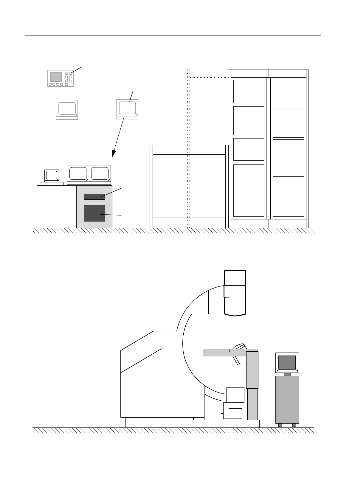
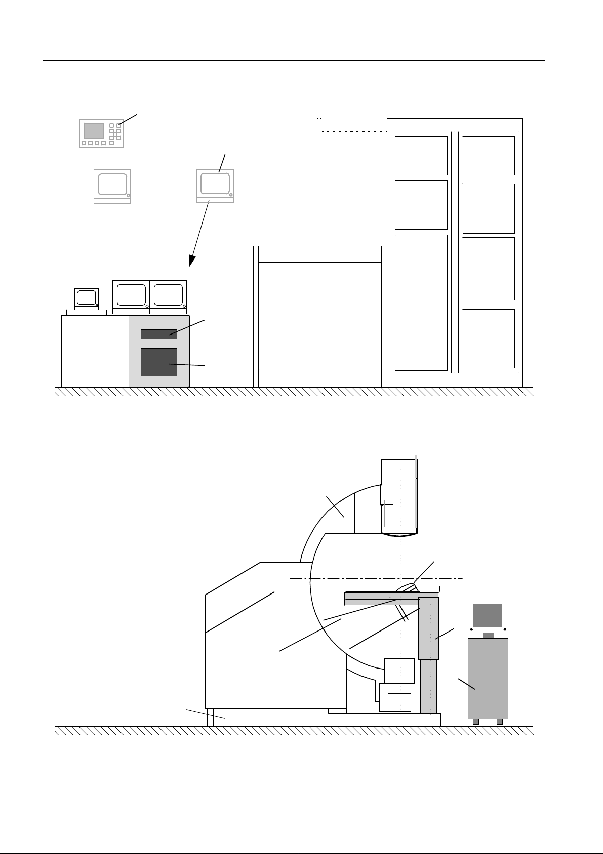
The "LITHOSTAR Multiline system" is a multifunction workstation for diagnosis and therapy involvin g extrac orporeal shock wave lithotr ips y w it h radiographic and optional ultrasound imaging. The system is excellent for the
treatment of stones throughout the entire urinary tract as well as for all suitable auxiliary treat m ents required.
Laser light loc alizer for preposi tio ning the patient
The system includes an undertable X-ray unit permanently mounted on a Carm. In addition to conventional use of the system for diagnostic purposes
(0°), the C-arm can be moved orbitally for the purpose of stone localization
(-10°/30°).
The focal point of the shock wave head (maximum shock) is located in the
center of both localiz at ion ranges (isocenter). In line technology enables
observation of ston e f ragmentati on t hrough the sh ock wave source.
Additional stone localization is made possible via the ultrasound monitor by
inserting an ultrasound probe in the shock wave head (Inline Position).
System control
US control
Documentation
“Work
authorization”
Oper ating modes
The system is controlled at a control console via a PC with keyboard and
mouse as well as a tableside control. A tableside control is also available on
the patient table. The table can be lowered to 720 mm to provide comfortable
access for the p at ient.
A tableside control is loc at ed on the Ultra so und unit for important fu nc t ions
such as: probe movement, shock wave release, shock wave counter, probe
angle display.
Hardcopy doc um entation is als o possible us ing film
(cassette size 35 x 43 cm) via an insertable cassette holder.
To guarantee system functions, only service engineers with work authorizations for the LITHOSTAR Multiline may service this system.
Two operating modes are possible:
Diagnostic mode (table insert locked in)
Therapy mode* (table insert removed)
*with X-ray or ultrasound localizat ion
Siemens AG Register 7 RXL2-120.041.01 Page 3 of 12 LITHOSTAR Multiline
Medical Engineering Rev. 03 09.97 TD SD 34
Page 8

1 - 4 System Overview
SC
3rd monitor (option)
PCMonitor
Monitor I + II
SIRECUST
(option)
Respiratory / ECG
Monitor (option
System-
control-
console
Multispot
(option)
Polydoros
LX
)
AC
Polydoros
SX
Charg-
ing unit
”HPE”
N12
Shock
wave-
control
Water-
cooling
circuit
A13
VIDEO-
MED
-DIM-
Image-
storager
N11
System
controlle r
M16
Pow.sply
A12
Basic system
A
D
US monitor
E
(SONOLINE
Prima)
(option)
B
C
F
LITHOSTAR Multiline Register 7 RXL2-120.041.01 Page 4 of 12 Siemens AG
Rev. 03 09.97 TD SD 34 Medical Engineering
Page 9

System Over vie w 1 - 5
System components 1
Basic versions
Main system features
Notice:
Basic system
• System type 1----- LITHOSTAR Multiline
• System type 2----- LITHOSTAR Multiline Pro
• System type 3----- LITHOSTAR Multiline Uro Plus
In additio n t o th e features of system types 1 and 2, syste m ty pe 3 features a
different X-ray gene rat or and image int ensifier.
• System types 1 and 2:------with POLYDOROS LX and 23cm I.I.
• System type 3:------------- POLYDOROS SX / 33cm I.I.
For additional details, refer to the data sheets.
The ultrasound optio n c an be installed in all of the s y stems.
A: Basic frame
System lo ngitudinal m ovement
Drives, table lift / tilt , lo ngitudinal moveme nt , footswitche s
B: Patient table
Two lifting columns, ta blet op carrie r, tabletop
Uro ins ert, head extension, foot extension, ta bles ide control panel
C: System carr i er
Support frame, C-arm support, shock wave system support, C-arm
orbital drive, shock wave system drive, system transverse movement
drive
D: C-arm
I.I. / TV system, adapter unit, X-ray tube assembly
Collimator N
E: Shock wave system support
Shock wave head M, Sys t em c arrier, Shock wave genera tor,
coupling system
F: Ultrasound unit
Siemens AG Register 7 RXL2-120.041.01 Page 5 of 12 LITHOSTAR Multiline
Medical Engineering Rev. 03 09.97 TD SD 34
Page 10
1 - 6 System Overview
SC
3rd monitor (option)
PC
Monitor
Monitor I + II
SIRECUST
(option)
Respiratory / ECG
Monitor (option
System-
control-
console
Multispot
(option)
Polydoros
LX
)
AC
Polydoros
SX
"HPE"
charg-
ing unit
N12
Shock-
wave-
control
Water-
cooling
circuit
A13
VIDEO-
MED
-DIM-
Image
storage
N11
System
control
M16
Pow.sply
A12
Basic unit
A
D
US Monitor
E
(SONOLINE
Prima)
option
B
C
F
LITHOSTAR Multiline Register 7 RXL2-120.041.01 Page 6 of 12 Siemens AG
Rev. 03 09.97 TD SD 34 Medical Engineering
Page 11

System Over vie w 1 - 7
Shock wav e cabinet
A 13
Contr ol cabi net
A 12
➪ Charging unit HPE
Suppli es high voltage to the shock wave generator.
➪ Shock wav e contro l
Coordinates and m onitors shock wave release and data transmission
to the main process or (HOST). Th e wa t er process controller is
included in this cabinet.
➪ Water cooling c irc uit
Cools the water heat ed by th e s hock wave head (E) in the coo ling circuit. The mechanical parts such as v alv es , filte rs, hose inter fa ces, etc.
are contained in this unit.
➪ Image st orage
Stores th e im age signa ls in th e F luoroscopy an d s nap shot mo des*.
The Me m os ko p 100-L ca n s t ore up to 100 images.
➪ Videomed DI -M
TV system with 50/60 Hz 625/525 lines. The image acquisition system (the camera) contains a CCD chip. "M" stands for motor-controlled iris diaphragm (controlled by the Host via the Motor end stage
D4).
➪ System control
Consist s of var ious compo nents for control and monitoring of the
entire s yst em (refer to the block diagram, page 1-8).
➪ Power supply
Power supply for the basic system and controls.
Also co nt ains the elem ents of the sa fety circ uits.
*optional
Siemens AG Register 7 RXL2-120.041.01 Page 7 of 12 LITHOSTAR Multiline
Medical Engineering Rev. 03 09.97 TD SD 34
Page 12
1 - 8 System Overview
HOST
D1
XCS
Controller
D2
Bright.act.val
COM
Controller
DUEP
Service PC
Videomed
DI
NBF
on
unit
NBF
FT
on
unit
Generator
NBF
US
*
NBF
on
con
sole
XCU
System
Contr.
PC
(BF)
XCS-net
SWL
Syst.
Service PC
Memo
3/100*
M3
M1
M2
*
I.I.
UB=ok?
FOC
M
M
W
TL
US
*
M
M
Resp.
Trig. *
O
*
TR
ECG
M
IB
* optional
Zoom and gray scale filter
CAN
S
M
P
M
B
U
S
D6
MC 1
D4A
Circuit
Func-
tions
M
ZL
Safety
Colli-
mator
M
ZR
MC 2
D4B
M
X
M
Y
A/D
D5
REF
LITHOSTAR Multiline Register 7 RXL2-120.041.01 Page 8 of 12 Siemens AG
Rev. 03 09.97 TD SD 34 Medical Engineering
Page 13
System Over vie w 1 - 9
NBF
Service PC
HOST
D1
XCS
Controller
D2
COM
Controller
D6
PC
(BF)
SWL
Syst.
Memo
3/100
Colli-
mator
N
I.I.
US
Resp.
ECG
Trig.
safety
circuit
safety
circuit
mats
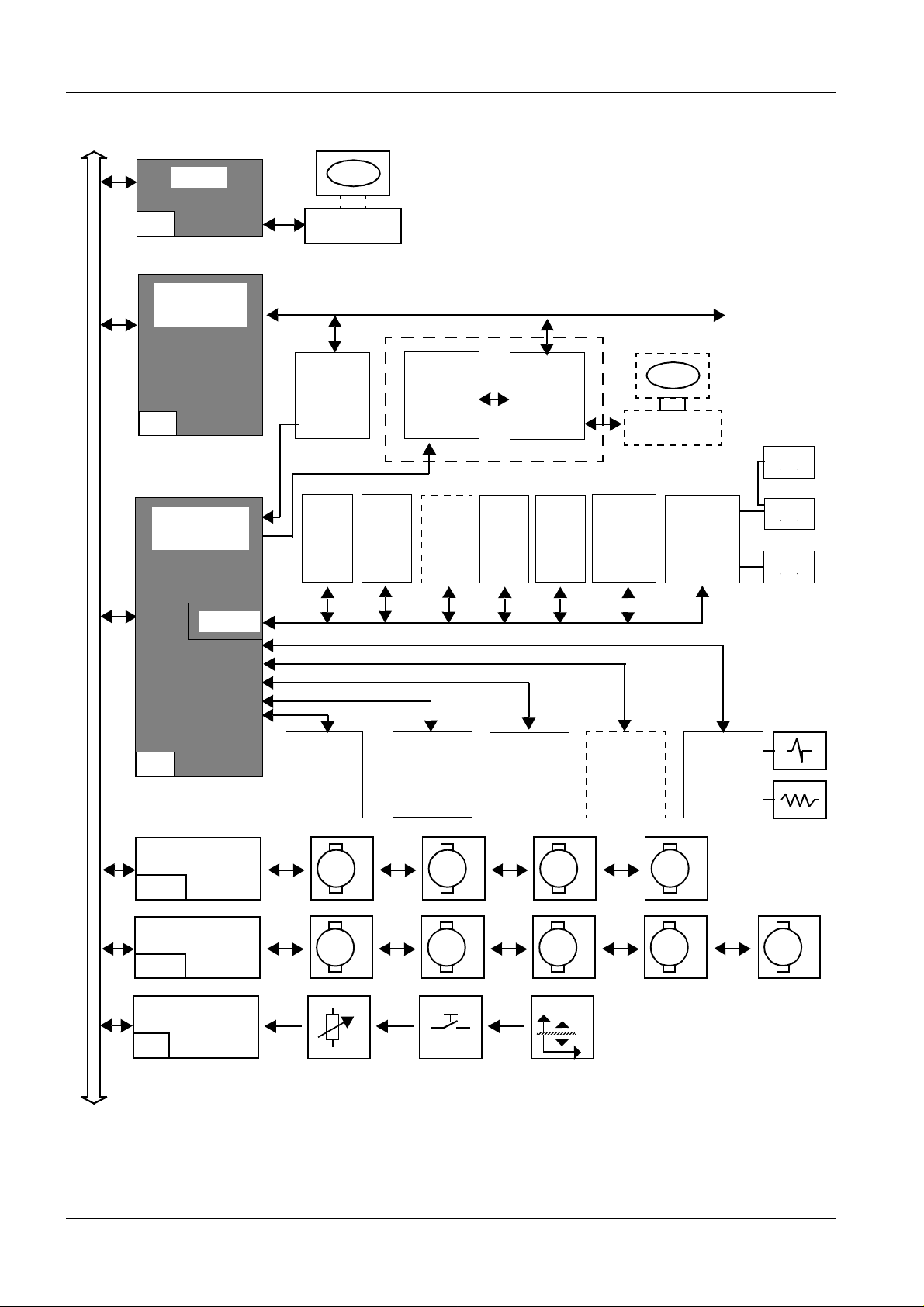
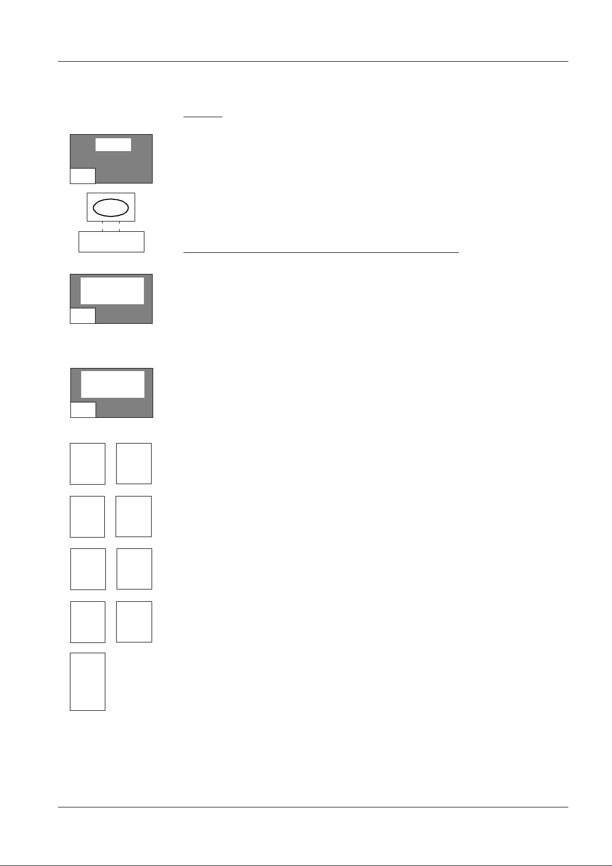
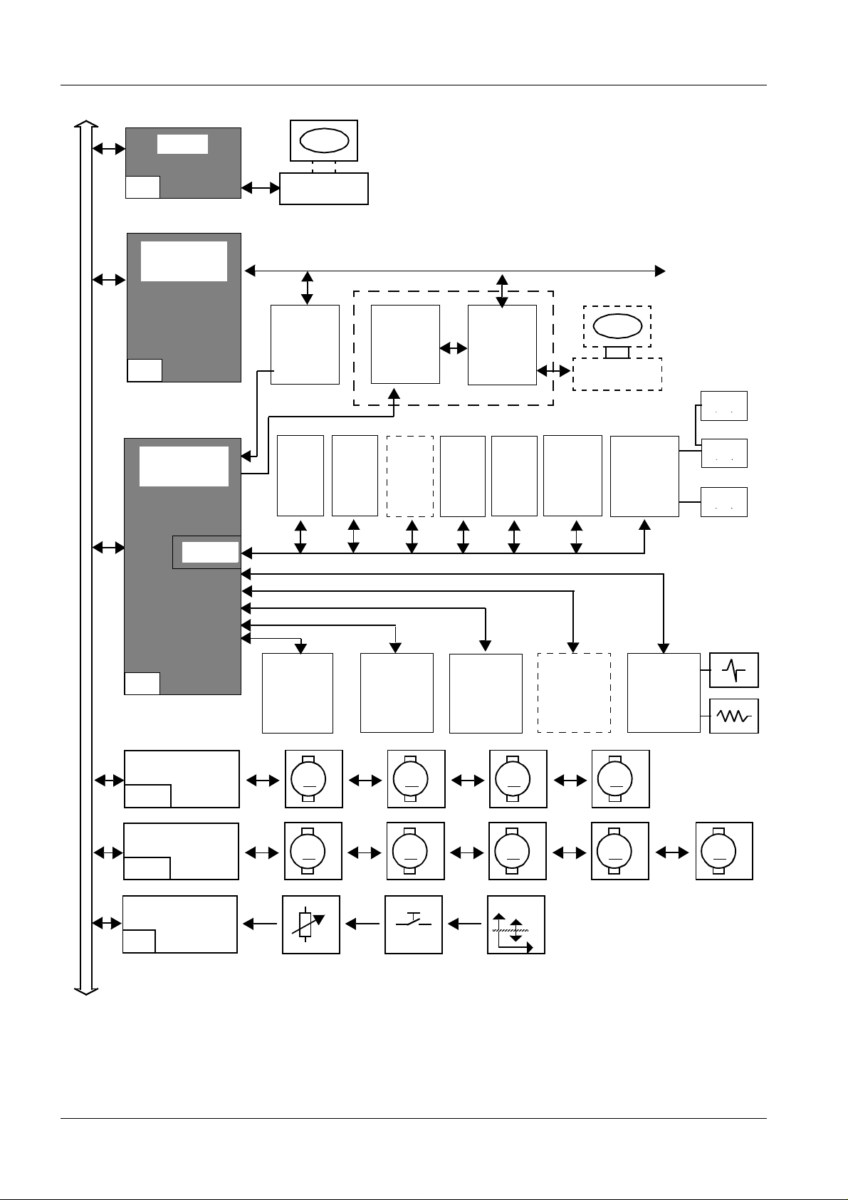
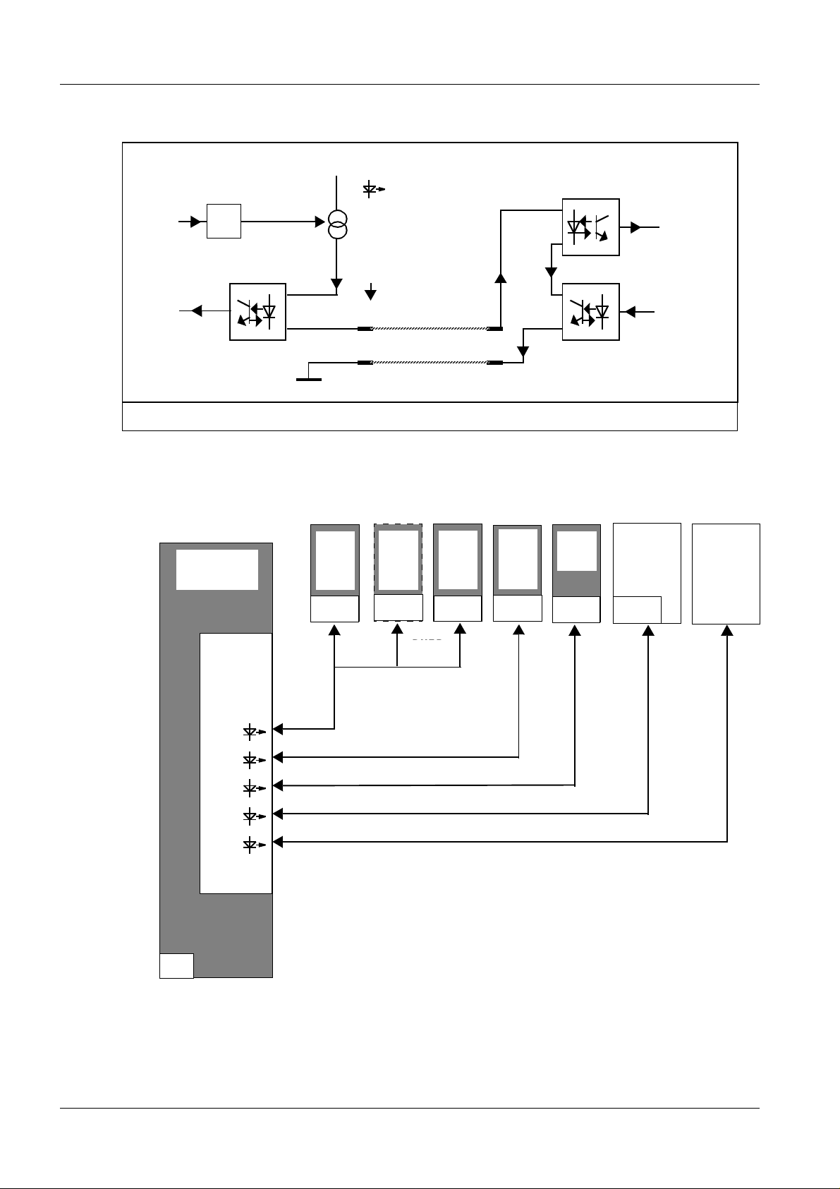
System controls 1
TASKS:
System control and system monitoring
(System start, hardware tests, Service PC interface
Data communication to the external units (via D2 and D6)
(Establishes c ontact with th e XC U in the X-ray generat or)
Simulates functions of generator operation and TV system (via D2).
(FE = Funktionseinheit (function unit).
Manages errors via a four-digit error code system.
The ser v ic e PC interface is loc ated on the H OST board
The XC S Controller (X-Ray Comm unication Sy s t em ) acts as
an interface to the XCS network (serial communication system).
The H os t commu nicates wit h t he XCU via the XCS Cont roller.
(X-Ray Contr olling Unit). Th e XC U is located in the POLYDOR OS generato r.
This is the central interface m odule for communication bet w een the
HOST(D1) and the function unit s c onnected.
1) Serial interfaces DUEPs (Data transmission protocol) to the:
➪ Operating PC....................................................(PC)
➪ System and Ultrasou nd tableside co nt rol panel,
system footswitch........................................(NBFG, NBFUS*, NBFFT)
➪ Water system and shock wave release....(SWL Syst.)
➪ Image storage...... .................................... ........(Memoskop 3/100)
➪ Control console.....................................................(NBF)
2) Serial interface for collimator N via CAN (Contr oller Area Network)
3) I/O Interace fo r image intensifier I.I. (Zoom selection)
4) I/O Interface for Ultrasound SONOLINE Prima
5) Serial interface for respiratory and ECG Triggering
6) additional in/output por t s are available to the Hos t for monitoring
and control of:
➪ the safety circuit and the safety circuit mats
➪ reference switch es for the drives
➪ casset te expo su res, FL, prep, main release
Siemens AG Register 7 RXL2-120.041.01 Page 9 of 12 LITHOSTAR Multiline
Medical Engineering Rev. 03 09.97 TD SD 34
➪ image m emor y (Memoskop) , shock wave release, etc.
Page 14

1 - 10 System Overview
HOST
D1
XCS
Controller
D2
Bright.act.val
COM
Controller
DUEP
Service PC
Videomed
DI
NBF
on
unit
NBF
FT
on
unit
Generator
NBF
US
*
NBF
on
con
sole
XCU
System
Contr.
PC
(BF)
XCS-net
SWL
Syst.
Service PC
Memo
3/100*
M3
M1
M2
*
I.I.
UB=ok?
FOC
M
M
W
TL
US
*
M
M
Resp.
Trig. *
O
*
TR
ECG
M
IB
* optional
Zoom and gray scale filter
CAN
S
M
P
M
B
U
S
D6
MC 1
D4A
circuit
functions
M
ZL
Safety-
Colli-
mator
M
ZR
MC 2
D4B
M
X
M
Y
A/D
D5
REF
LITHOSTAR Multiline Register 7 RXL2-120.041.01 Page 10 of 12 Siemens AG
Rev. 03 09.97 TD SD 34 Medical Engineering
Page 15
System Overview 1 - 11
D7
MC 1
M
MCx
D4x
A/D
D5
Block diagram 1
Motor controller MC1 Motor controller MC2
ZR: Right lifting column A M1 X: System transverse drive AM5
ZL: Lef t lifting column AM2 Y: System longitudina l drive AM6
W: Shock wave head AM3 IB: Iris diaphragm AM7
O: Orbit al (C-arm) AM4 TL: Cone lon gitudi nal drive AM8
TR: Cone rotation (optional) AM9
TASKS:
➪ MC: The motor controller controls or regulates the system motors.
Commands for the mot ors are transmitt ed via the Du alport R AM of
the HOST (D1). Two motor controllers are used. Each one can control
a maximum of five motors.
NOTICE
➪ A/D: Co nverts the analog input voltage of the actual value potent iom-
eter and t he operating voltages.
➪ Quer ies t he reference switches .
There are 16 channe ls w it h 10 bit resolut ion and 16 digital inputs available.
The motors are controlled via timed motor end stages.
(D7..).
An enco d er and a poten tiometer are us ed to co mmuni cate the current movement and position of the motor.
Siemens AG Register 7 RXL2-120.041.01 Page 11 of 12 LITHOSTAR Multiline
Medical Engineering Rev. 03 09.97 TD SD 34
Page 16

1 - 12 System Overview
This page int entionally lef t blank .
LITHOSTAR Multiline Register 7 RXL2-120.041.01 Page 12 of 12 Siemens AG
Rev. 03 09.97 TD SD 34 Medical Engineering
Page 17

Control Panels 2
This pag e int entionall y lef t blan k .
2 - 1
Siemens AG Register 7 RXL2-120.041.01 Page 1 of 8 LITHOSTAR Multiline
Medical Engineering Rev. 03 09.97 TD SD 34
Page 18
2 - 2 Control Panels
HOST
D1
XCS
Controller
D2
Bright.act.val
COM
Controller
DUEP
Service PC
Videomed
DI
NBF
on
unit
NBF
FT
on
unit
Generator
NBF
US
*
NBF
on
con-
sole
XCU
System
Contr.
PC
(BF)
XCS-net
SWL
Syst.
Service PC
Memo
3/100*
M3
M1
M2
*
I.I.
UB=ok?
FOC
M
M
W
TL
US
*
M
M
Trig. *
O
*
TR
Resp
ECG
M
IB
* optional
Zoom and gray scale filter
CAN
S
M
P
M
B
U
S
D6
MC 1
D4A
circuit
functions
M
ZL
Safety
Colli-
mator
M
ZR
MC 2
D4B
M
X
M
Y
A/D
D5
REF
LITHOSTAR Multiline Register 7 RXL2-120.041.01 Page 2 of 8 Siemens AG
Rev. 03 09.97 TD SD 34 Medical Engineering
Page 19
Control Panels 2 - 3
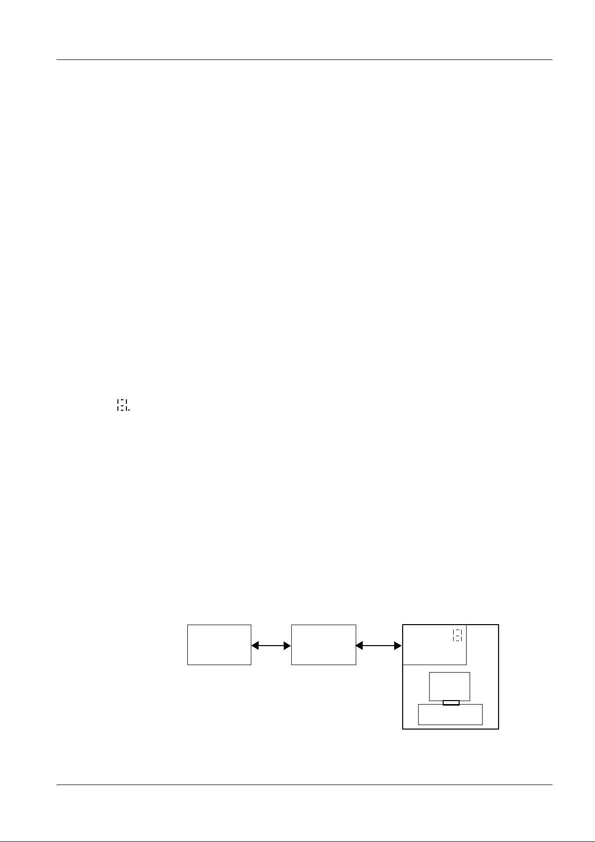
Operating PC 2
Components
Communication
D 51 Tasks
D51 Displays
Initializat ion
Seven-segment
Display.
➪ Central unit
➪ Monitor
➪ Keyboard
➪ Mouse
Data trans fer betw een the opera ti ng PC and the C OM contro ller takes place
via a serial DUEP interface, which is located on the ADC/DUEP PC D51 plugin board. T he D51 acts as a D U EP slave (pp 2-6) co m pared to the C OM controller.
Data trans fer betw een the PC and DUEP slave via the AT-B us of t he PC.
➪ Communication with the Com-Controller D6 via the DUEP 2 interface
➪ Communication w it h t he PC-AT-Bus via the Dual-Port Ram interface
1 seven segment, 1 Watch d og reset, 1 bo ot m ode
1 life sign AT-Bus, 1 life sign DUEP.
Tests the hardware, initializes the components, establishes contact with the
HOST and with the operating PC.
Visible only when the PC housing is open
0: Normal mode
1: DUEP communication error, DPR ok
2: DPR communcation error, DUEP ok
3: DPR and DU EP commun ic at ion error
4: Error in the analog component
5 Clock error
5: External RAM error
7: E PRO M or program RAM error
8: E rror-free initilization but no D PR c ontact & no DU EP contact
9: n .c.
DP: Decimal point flashes; 80C535 µP vital sign
HOST
D1
DUEP: Data transmission protocol
(refer to descr iption)
DPR: Du al por t RAM
COM
Controller
D6
DUEP 2
ADC
DUEP-D51
xxxxxx
xxxxxx
Oper. PC
Siemens AG Register 7 RXL2-120.041.01 Page 3 of 8 LITHOSTAR Multiline
Medical Engineering Rev. 03 09.97 TD SD 34
Page 20

2 - 4 Control Panels
HOST
D1
XCS
Controller
D2
Bright.act.val
COM
Controller
DUEP
Service PC
Videomed
DI
NBF
on
unit
NBF
FT
on
unit
Generator
NBF
US
*
NBF
on
console
XCU
System
Contr.
PC
(BF)
XCS-net
SWL
Syst.
Service PC
Memo
3/100*
M3
M1
M2
*
I.I.
UB=ok?
FOC
M
M
W
TL
US
*
M
M
Trig. *
O
*
TR
Resp
ECG
M
IB
* optional
Zoom and gray scale filter
CAN
S
M
P
M
B
U
S
D6
MC 1
D4A
circuit
functions
M
ZL
Safety
Colli-
mator
M
ZR
MC 2
D4B
M
X
M
Y
A/D
D5
REF
LITHOSTAR Multiline Register 7 RXL2-120.041.01 Page 4 of 8 Siemens AG
Rev. 03 09.97 TD SD 34 Medical Engineering
Page 21
Control Panels 2 - 5
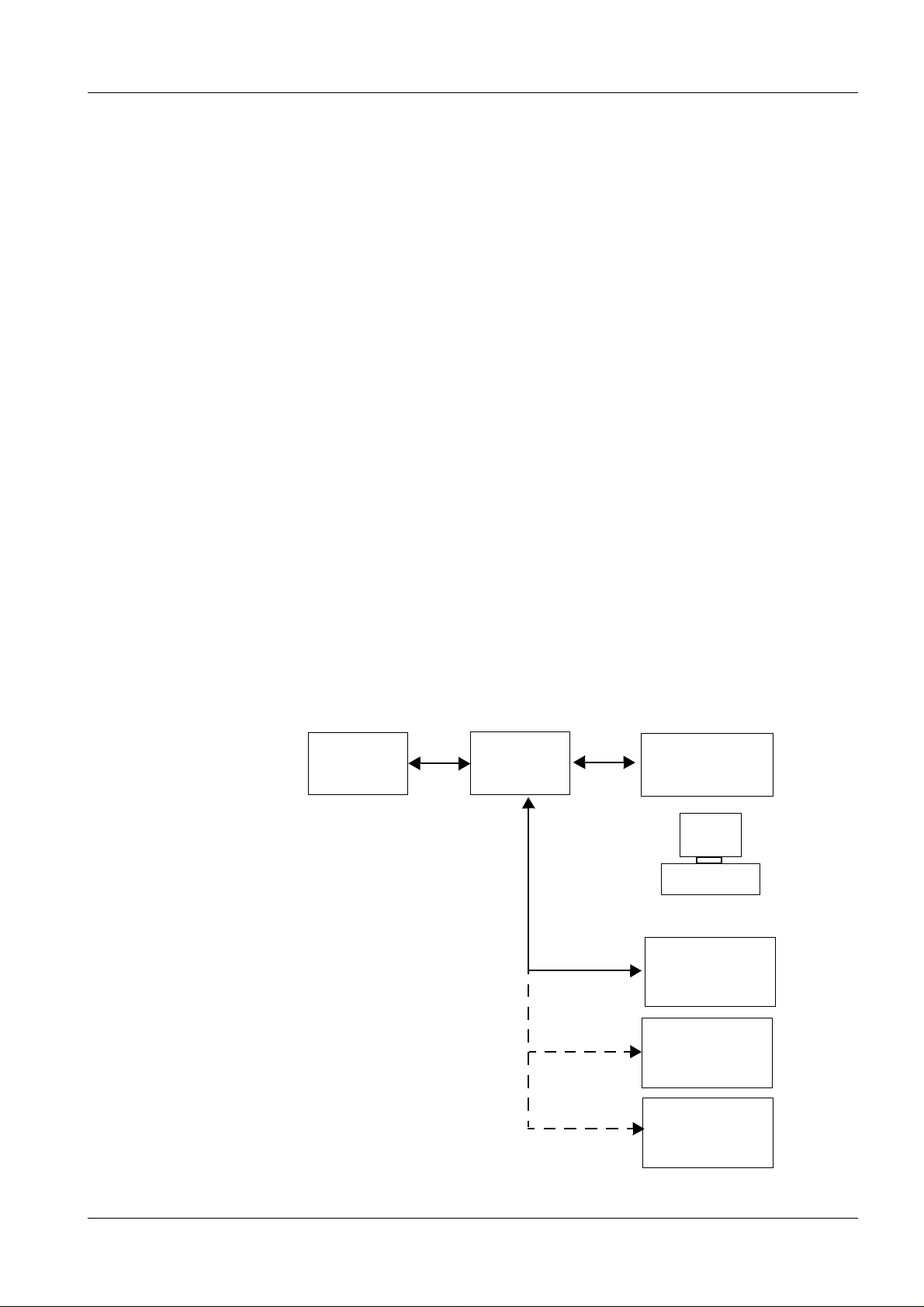
Main control panel a nd tableside co ntrol panel 2
Tableside control
panel
Communication
Initialization
Erro r handl in g
Tableside control panels
In additio n t o th e PC operation, some op erat ing functio ns are available
directly at the system. These operating functions are limited to syste m functions and functions for urological examinations (image storage, zoom etc.). In
addition, the tableside control panel on the PC, the tableside control panel on
the unit, the system footswitch and the US tableside control panel may also
be used.
Data trans fer betw een the opera ti ng panel and t he COM con tr oller takes
place via a serial DUEP interface.
Tableside control (c onsole) ➝ DUE P 4
Tableside control (unit)
The most important tasks are: basic initialization and hardware tests and
time-out m onitorin g (establishin g c ontact). Error handling is import ant when
serv ic e w ork is being performed.
Hardware errors: LED’s flash in all keys. (approx. 5 Hz)
Establishing contact: Initial contact. LED’s flash sequentially in keys
Polling time out: LED’s in all keys flash. (ap prox. 1 H z )
➝ DUE P 1
D41:
HOST
D1
Configurable via
address DI P-switch as
tableside control at PC
or at the patient table
(refer to block diagram)
Control ler
COM
D6
DUEP 4
DUEP 1
DUEP 1
DUEP 1
Main
contr ol panel
D41
xxxxxx
xxxxxx
Operat. PC
at patient ta ble
Tableside cont.
D41
*
Tabl es ide con t .
US
System
footswitch
Siemens AG Register 7 RXL2-120.041.01 Page 5 of 8 LITHOSTAR Multiline
Medical Engineering Rev. 03 09.97 TD SD 34
Page 22
2 - 6 Control Panels
DUEP Master
TxD
RxD
COM
Controller
V
cc
DUEP S lave
Vxx
1
RxD
20mA
TxD
Function principle of DUEP interface
NBF
on
unit
D41
NBF
US
*
D41/43
NBF
FT
on
unit
D41
NBF
console
D41
PC
(BF)
D51
SWL
Syst.
W16
Memo
3/100*
D6
DUEP
Master
V13
V7
V11
V9
V69
DUEP 1
DUEP-DUEP 1DUEP 1
DUEP 4
DUEP 5DUEP 3DUEP 2
LITHOSTAR Multiline Register 7 RXL2-120.041.01 Page 6 of 8 Siemens AG
Rev. 03 09.97 TD SD 34 Medical Engineering
Page 23

Control Panels 2 - 7
NOTICE
DUEP Interface 2
DUEP
Function
Serial dat a t rans m ission bet we en the master (Com con t roller D6) and th e
slaves (e.g. operatin g panels or image memory, etc.) occurs via a Siem ensstandarized data transmission protocol (DUEP).
The DUEP inter face is a 20mA current lo op.
Each curr ent loop has an LED as indicator on bo ard D6.
If the LED is "ON", it means: the loop is connected and 20 mA are present.
DUEP 1: Current loop 1 Tableside controls (system, US unit, NBFFT)
DUEP 2: Current loop 2 Operating PC
DUEP 3: Current loop 3 Shock wave system
DUEP 4: Current loop 4 Tableside control at the PC
DUEP 5: Current loop 5 Image memory
Telegra m s co nt aining comm ands to be performed are sent via the s e c urrent
loops (e.g. selecting functions or increasing values etc.). Even if no commands are p r ese nt , th e COM c ont ro l ler (D6 ) co nt i nuo usl y ch ec ks t he f unc ti on
of the interface. If n o s igns of life are present, the COM c ontroller trans it ions
to a security level and sends a failure message to the Host (D1). An error
message is displayed.
Possible
causes of error
Connection to the slave has been interrupted (e.g. damaged cable). The LED
goes out.
Connection to the slave has shorted out.
Assembly for resp ec t ive DU EP is defective.
The se r vi ce engineer (FSE) can d eactivate slaves via
the service program. This can be useful during error
localization. This method should, however, only be initiated by experienced service engineers. For example,
it is typical to see the LED’s flash sequentially in the
operati n g keys if initial co n tact from the op er ating
panel (D41) to the master (D6) does not occur.
Siemens AG Register 7 RXL2-120.041.01 Page 7 of 8 LITHOSTAR Multiline
Medical Engineering Rev. 03 09.97 TD SD 34
Page 24

2 - 8 Control Panels
This page int entionally lef t blank .
LITHOSTAR Multiline Register 7 RXL2-120.041.01 Page 8 of 8 Siemens AG
Rev. 03 09.97 TD SD 34 Medical Engineering
Page 25

System Startup 3
This pag e int entionall y lef t blan k .
3 - 1
Siemens AG Register 7 RXL2-120.041.01 Page 1 of 6 LITHOSTAR Multiline
Medical Engineering Rev. 03 09.97 TD SD 34
Page 26
3 - 2 System Startup
Switch on
Boot Sofware sta rt
Operating system initializes
Service PC
can be con-
nected here.
Self-test of processor system
Initialization
EEPROM
code
correct?
yes
Initializat ion of the
subsystems
Stand-by mode
no
Perform
Download
Error message
LITHOSTAR Multiline Register 7 RXL2-120.041.01 Page 2 of 6 Siemens AG
Rev. 03 09.97 TD SD 34 Medical Engineering
Page 27

System Startup 3 - 3
Simplified program sequence 3
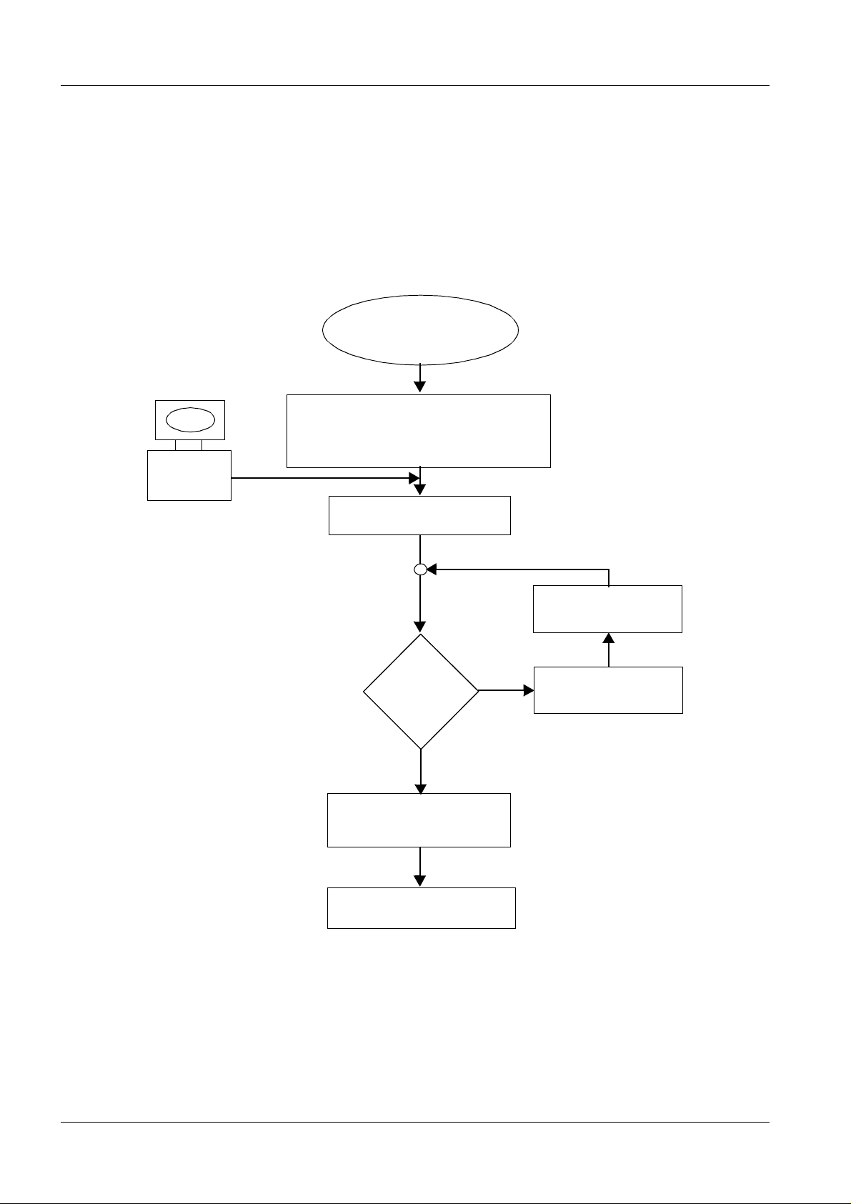
Switch on/
Switch off
In normal cases: at the control console. Key S30 switches ON and key
S31 switches OF F.
In case of service: at th e generator a t D160. Key S1 switches ON and
switch S2 switches O FF.
Initialization
Service PC
NOTICE
Step 1:
Switching the system off from the generator provides
additiona l sa fety for the servi ce engineer becau se the
system cannot be switched back on from the control
console.
• Starts bo ot soft ware
• Initialize operatin g system
• Processor system self-test
Simply stated, this first step initializes and tests the HOST board D1.
All subsystems are initialized in parallel.
The PC can be connected following completion of the first step.
Step 2:
• Starts initialization tasks
The version number of the HOST software is compared with the version number in the EEPROM.
Download
Establishing contact
with the subsystems
Siemens AG Register 7 RXL2-120.041.01 Page 3 of 6 LITHOSTAR Multiline
Medical Engineering Rev. 03 09.97 TD SD 34
If there is a discrepancy, the HOST will send an error message and will transition to a wait lo op. Onl y by dow nloading th e operating sof t war e in t he
EEPROM is it pos s ible t o c ontinue the initializatio n.
Step 3:
• Initialization routi nes of the subsystems
Contact with the subsystems is established in this part of the initialization. In
principle, the subsystem must contact the HOST after initial contact is established and vi c e versa.
As a rule, three attempts will be made to establish contact to the other if
errors occur during this data exch ange . If these atte mpts fail, the systems will
transition t o a s ec urity level and an error messag e w ill be displayed.
Page 28

3 - 4 System Startup
Switch on
Boot Sofware sta rt
Operating system initialization
Service PC
can be con-
nected here.
Processor system self-test
Initialization
EEPROM
code
correct?
yes
Initializat ion of the
subsystems
Stand-by mode
no
Perform
Download
Error message
LITHOSTAR Multiline Register 7 RXL2-120.041.01 Page 4 of 6 Siemens AG
Rev. 03 09.97 TD SD 34 Medical Engineering
Page 29
System Startup 3 - 5
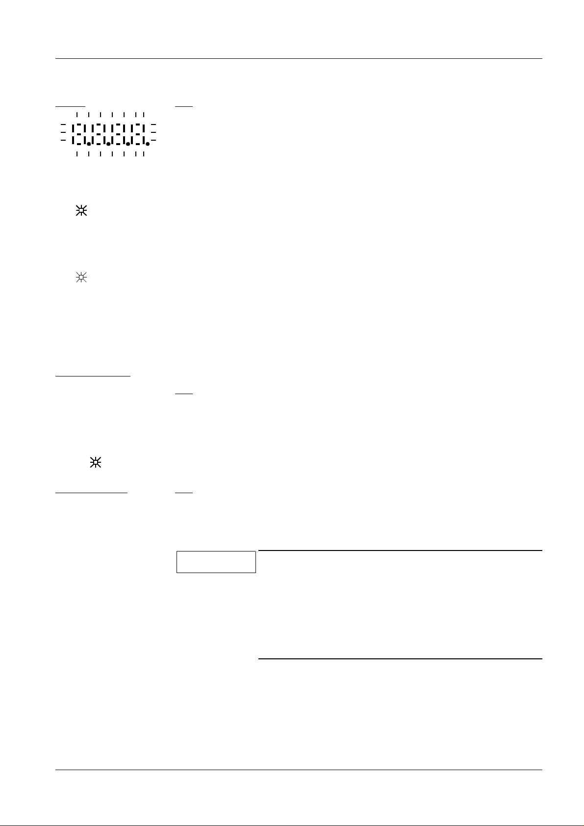
5 5
0 0 0 0
0 0 0 0
The 7-segment displays during system initialization.
HOST
V1,V7 on
V1,V7 on
V1 on
RESET
COM Controller
D1:
• All four 7-segment displays and decimal points light up after switching the
system on or after a system reset.
LED V1 (green) and V7 (red) are on.
• Four ’0’s are the n displ ayed with a f lashi ng deci mal poin t. V1,V 7 on.
• At the end of initialization, the four ’0’s, a flashing decimal point and V1 are
on.
• When activating the RESET switch, D1 reinitializes.
XCS Controller
D6:
• All displays and decimal points light up.
• Afterwards,➝50➝20➝40➝10➝30➝55➝36➝55 and a flash ing dec imal
point appear.
• Two ’5’s an d a flas hing dec imal poin t indic ate:
STATUS NORMAL.
D2:
• All display segments light up. Afterwards, two ’0’s and decimal point of LED
V2. The n
NOTICE
➝00➝31.➝60.➝31.➝61.➝30.➝61.➝00.
In the case of errors, these are the most important
boards to be monitored during initialization.
The normal condition for all boards is: ”Displays at 0
and flashing decimal points”.
If the US option is not present, "55" and "60" will also
be displayed.
Siemens AG Register 7 RXL2-120.041.01 Page 5 of 6 LITHOSTAR Multiline
Medical Engineering Rev. 03 09.97 TD SD 34
Page 30

3 - 6 System Startup
This page int entionally left blank.
LITHOSTAR Multiline Register 7 RXL2-120.041.01 Page 6 of 6 Siemens AG
Rev. 03 09.97 TD SD 34 Medical Engineering
Page 31

Interface I/O signals 4
This page intentionally left blank.
4 - 1
Siemens AG Register 7 RXL2-120.041.01 Page 1 of 4 LITHOSTAR Multiline
Medical Engineering Rev. 03 09.97 TD SD 34
Page 32

4 - 2 I nterface I/O signals
HOST
D1
XCS
Controller
D2
Bright.act.val
COM
Controller
DUEP
Service PC
Videomed
DI
NBF
on
unit
NBF
FT
on
unit
Generator
NBF
US
*
NBF
on
console
XCU
System
Contr.
PC
(BF)
XCS-net
SWL
Syst.
Service PC
Memo
3/100*
M3
M1
M2
*
M
M
UB=ok?
FOC
W
TL
US
*
M
M
Trig. *
O
*
TR
Resp
ECG
M
IB
* optional
Zoom an d gray sca le f ilt er (D R only)
CAN
S
M
P
M
B
U
S
D6
MC 1
D4A
circuit
functions
M
ZL
Safety
Colli-
mator
M
I.I.
ZR
MC 2
D4B
M
X
M
Y
A/D
D5
REF
LITHOSTAR Multiline Register 7 RXL2-120.041.01 Page 2 of 4 Siemens AG
Rev. 03 09.97 TD SD 34 Medical Engineering
Page 33

Interface I/O signals 4 - 3
Safety
circuit
functions
Memo
3/100*
I.I.
Overview 4
Task
Controls the following components:
➪ Relays in the safety circuit on board D21
➪ Start and Dow nload signa ls for the im age memory
➪ Signals for zoom levels
➪ Safety switches
➪ Respira to ry gating learning phase and respiratory trigger ON/OFF
➪ Move gray scale filter IN/OUT
Reading in information:
➪ Safety circuit s ignals (collis ion protect ion)
➪ Limit switch es for the drives
➪ Reference switches
➪ Cassette switch for exposures on film (Direct Radiography)
and cassette holder present
➪ Shock w ave releas e
➪ FL, Prep, Main release
➪ Aquisit ion in progres s fro m im age memory
➪ US probe in shock wave head
Errors
Safety circuit
Reference switches
A/D conver t er
Powersupplies
➪ Cone pressure switch
If an error o ccurs, it will be dis played an d t he corresponding ac tio n released.
The safety circuit (large and small drives) can be interrupted by activating the
emergency shutdown buttons, collision protection switches or the safety limit
switches.
The reference swit c hes m onitor defined positions of the dr ive s. (R efer to th e
chapter on motor control).
Via the A/D converter, v arious voltages are tested against the nominal values
and values of th e potentiom eter positi oned on the motor axes are rea d in.
The f ollowing voltages ar e checked:
➪ System dri ves
➪ Small drives
➪ +5V / +24V
NOTICE
The safety, monitoring and control circuits are
explained in greater detail in the individual chapters.
The port signals ar e accessi ble via the ser vi ce PC.
Siemens AG Register 7 RXL2-120.041.01 Page 3 of 4 LITHOSTAR Multiline
Medical Engineering Rev. 03 09.97 TD SD 34
Page 34

4 - 4 I nterface I/O signals
This page int entionally left blank.
LITHOSTAR Multiline Register 7 RXL2-120.041.01 Page 4 of 4 Siemens AG
Rev. 03 09.97 TD SD 34 Medical Engineering
Page 35

Motor Control 5
This page intentionally left blank.
5 - 1
Siemens AG Register 7 RXL2-120.041.01 Page 1 of 14 LITHOSTAR Multiline
Medical Engineering Rev. 03 09.97 TD SD 34
Page 36

5 - 2 Motor Control
Host
Com Ctr.
A/D I/O
D1
D6
DUEP
I/O
D5
A/D
I/O
Service
PC
DUEP
Safety circuit
Potentiometer
R1 TO R9 ( 10 KOHM )
Reference switches
S1 TO S9
NBF Unit
NBFConsole
NBF US
NBF FT
Oper.PC
P. supply
D7a to D7E
Motor end stages
Travel range
Mechan. end stop
Safety limit switch
Software en d swi tc h.
Refer ence switches
Software en d swi tc h
Safety limit switch
Mechan. end stop
D4A
8032 µP
control-
system
MC1
MC2
MC3
MC4
LS
LS
LS
LS
D7A
D7A
D7A
D7B
D7B
M
AM1
M
AM2
M
AM3
M
AM4
R1 S1
B1
R2 S2
B2
R3 S3
B3
B4 R4
MB3
S4 MB4
Table lift
ZR Column drive
Table lift
ZL Column drive
Shock wave
head drive
C-arm
O Drive
MC0
LITHOSTAR Multiline Register 7 RXL2-120.041.01 Page 2 of 14 Siemens AG
Rev. 03 09.97 TD SD 34 Medical Engineering
Page 37

Motor Control 5 - 3
acceptable values in test range
Ref.
Switches
Switch ca m
0
1
1 or 0
1 or 0
0
Overview 5
General
Movement command
Relative current
position
Absolute current
position
Travel range
By activati n g a key o n th e control pan el (ta bles ide or operati ng PC ) a
command is activated (FB) and the following oc c urs:
➪ Via the DUEP interface and the Com Controller D6, the movement
command goes to the HOST D1.
➪ The Host forwards the command, speed to the responsible motor con-
troller (D 4A, D4B).
➪ The motor controller activates the motor via the end stage D7x and
the movement begins.
➪ An incremental transmitter (Bx) connected to the motor axle reports
the curr ent position (M C value ). T he m otor contr oller transmits t his
actual value to the HOST for further evaluation.
➪ At the same time, the potentiometer that acquires the system position
is also turning. Th e analog value p roduces the abs olute actu al val ue
of the po te nt iometer after conversion in the A/D conver te r (D 5). This
ADC value is read out by the Hos t at regular intervals.
The travel range is limited by means of software limit switches (SE) and safety
limit switches (refer to the safety circuit).
SE
Reference switches
possible err ors
This value is de te rmine d in t he testing field and can not be change d by the
serv ic e engineer.
The reference switches (S1-S9) are necessary only to monitor the potentiometers. They are loc ated at certain points within the travel range ( e.g. sy stem
long itudinal travel zero position, etc .) and are activated by a switch ca m , e .g.
each time t he drive pass es th e switch cam. When the HOST receives the
message via the I/O port (D5) ” Ref.switch on”, it checks the current actual
value of the potentiometer where the value is stored for this reference switch.
THIS IS OF GREATEST IMPORTANCE IN THE THERAPY POSITION.
In the therapy position , th e sh o ck wave focus must c o incide with th e
cross hairs target.
The H OST basically rec ognizes hardware errors or communi c at ion errors
between the processor systems.
If a motor, an actual valu e potentiom et er or an encoder is defective, the
HOST imm ediately is s ues an error message. For example:
➪ The difference between the ADC value and the MC value is too large
(two-channel acq uis it ion).
Siemens AG Register 7 RXL2-120.041.01 Page 3 of 14 LITHOSTAR Multiline
Medical Engineering Rev. 03 09.97 TD SD 34
Page 38

5 - 4 Motor Control
D4B
MC1
8032 µP
control-
system
MC1
MC2
MC3
MC4
MC5
LS
LS
LS
LS
LS
D7C
D7A
D7C
D7D
D7D
D7E
M
AM5
M
AM6
M
AM7
M
AM8
M
AM9
R5 S5
B5
R6 S6
B6
R7
B7
B8 R8
B9 R9
S8
S9
Transverse mvmt.
X drive
MB5
Long. moveme nt
Y drive
MB6
Iris diap hragm
IB drive
Cone long.
TL drive
Cone rota tio n
TR drive *
(optional)
LITHOSTAR Multiline Register 7 RXL2-120.041.01 Page 4 of 14 Siemens AG
Rev. 03 09.97 TD SD 34 Medical Engineering
Page 39

Motor Control 5 - 5
possible err ors
Notice
➪ or the potentiometer value deviates from the reference switch nominal
posit ion
➪ or the Rx potentiometer has a broken wiper, etc.
The error m es s age is read out at the HOST (D1 ).
There are c erta in im port ant items th at th e s ervice engineer mu st kn o w:
1) After executing a switch-on or Reset, the values ADC position = MC
position must be identical in the service program: DIAGNOSTIC / MONITORING.
The operating software sets the first position value (starting value) for the
motor controller (MC position) based on the a ctual value of the p ot entiometer su pplied by the A/D c onverter (AD C position). Thereafter, the
encoder s upplies the difference betw een the actu al position and the current posi ti on. T he encode r c an m easure on ly relative values.
2) In the service program menu ”ADJUSTMENT/CALIBRATION”, there is
an ”UNREGULATED MODE” selection that allows th e motor to be
moved without feedback signals from the potentiometer or the encoder.
The sele c te d m ot or will move at reduc ed speed in th is operating mod e
(can be adjusted via th e s ervice PC).
This ope rat ing mode is us ed for calibration an d for er ror removal (e.g.
drives in the safety circuit).
Safety informat ion
Use CAUTION when operating the system in ”UNREGULATED MODE”.
A collision can easily occur since the monitoring functions are disabled. Watch all moving parts of the system.
NOTICE
The reference switches are not monitored in urology
mode (table insert). In case of an error, e.g. reference
switches not ok in therapy position, you can switch
over to urology mode and move out of this position
after performing a syst em reset.
Siemens AG Register 7 RXL2-120.041.01 Page 5 of 14 LITHOSTAR Multiline
Medical Engineering Rev. 03 09.97 TD SD 34
Page 40

5 - 6 Motor Control
Displays for imp o rtant system positions on th e operating mo n i to r
Pat. transf. pos.
Urology basic position
O:
X:
Y:
Z:
W:
TL:
TR:
1000 mm
Park Pos.
O
Positions:
Orbital movement
X
Travel range:
Vertical movement
0°
-60 mm
0 mm
40 mm
0°
C-arm drive
O:
X:
Y:
Z:
W:
yes
maximum travel range
0,-10,+30
degrees
X drive
+120 /-350 mm
30°
-350 mm
0 mm
720 mm
Par k Pos.
Table insert
present?
0
NBF
NBF
NBF
no
Therapy basic position
O:
X:
Y:
Z:
W:
TL
TR:
Gel position
O:
X:
Y:
Z:
W:
Therapy-Pos.
actual Pos.
TL:
act. Pos./0 deg.
TR:
0°
20 mm
0 mm
1033 mm
Park-Pos.
40 mm
0°
-10°
120 mm
0 mm
1116 mm
Y
Travel range:
Horizontal movement
Tra ve l range:
R
Z
Table lift
L
W
Travel range:
Shock wave head drive
Y drive
+320 /-320 mm
Z drive
+1116/+720
W drive
+0 /+450 mm
NBF
NBF:
Therapy position
O:
depending on
X:
ston e posi tio n
Y:
(localization)
Z:
W:
Therapy Pos.
remains act. Pos.
TL:
remains act. Pos./ 0 deg
TR:
Control panel at the console
Contr ol panel at
Oper at ing PC
TL/TR: refer to the chapter :Ultrasound function unit
LITHOSTAR Multiline Register 7 RXL2-120.041.01 Page 6 of 14 Siemens AG
Rev. 03 09.97 TD SD 34 Medical Engineering
Page 41

Motor Control 5 - 7
Important system positions 5
Patie nt tra nsfer
position
Basic positions
This system position allows the patient easy access to the table. The image
intensifier has been m oved as far as possible out of th e range of the table.
The HOS T always know s th e actual pos it ion values of the m ot or drives and
automatically steers the drives in the correct direction after comparison with
the ascending parameters.
Releasing the drives in the patient transfer position
The bas ic sys tem po si ti on is rel ea se d. The LED i n the tableside con tr ol pa ne l
key flashes.
Drives required for the patient transfer position
In the worst case, the HOST activates the following drives:
(X,Y,ZR,ZL,W,O,TL,TR*,)
There are t wo bas ic position s :
➪ The bas ic position for urolo gy mode
➪ The bas ic position for therapy mode
Table insert in s ta lled: Urology mode
Table insert n ot ins t alled: Therapy mode
Basic position indicators for Urology mode
➪ Working table height for Urology mode (Z = 1 000mm)
(Travel range 900 - 1100)
➪ C-arm in the 0° position (Travel range -10° / +10°)
➪ Shock wave head in park position
➪ System carrier
X = -60 Travel range +70mm / -1 30mm
Y = 0 Travel rang e +/ - 320mm
Basic position indicators for Therapy mode
➪ Working ta ble height for Therapy mode (Z = 1033mm)
(Travel range 970 -1070)
➪ C-arm 0° (Travel range +30 / -10°)
➪ Shock wave head in park position
* opti onal
Siemens AG Register 7 RXL2-120.041.01 Page 7 of 14 LITHOSTAR Multiline
Medical Engineering Rev. 03 09.97 TD SD 34
Page 42

5 - 8 Motor Control
Operating monitor displays for the most important system positions
Pat. transfer pos.
Urology basic position
O:
X:
Y:
Z:
W:
TL:
1000 mm
Par k Pos.
0°
-60 mm
0 mm
TR:
O
Positions:
Orbital movement
X
Travel range:
Vertical movement
C-arm drive
O:
X:
-350 mm
Y:
Z:
W:
yes
720 mm
Park Pos .
T able insert
present?
NBF
maximum travel range
0,-10,+30
degrees
X drive
+120 /-350 mm
30°°
0 mm
0
NBF
NBF
no
Therapy basic position
O:
X:
Y:
1033 mm
Z:
Park Pos.
W:
TL:
TR:
Gel p osition
O:
X:
Y:
Z:
W:
TL:
actual Pos.
TR:
actual Pos./0 deg
0°
20 mm
0 mm
40 mm
0°
-10°
20 mm
0 mm
1033 mm
T.Pos.
Y
Travel range:
Horizontal movement
Travel range:
R
Z
Ta ble lift
L
W
Travel range:
Shock wave head drive
Y drive
+320 /-320 mm
Z driv e
+1100/+720
W drive
+0 /+450 mm
NBF
NBF:
Therapy position
O:
X:
Y:
Z:
W:
TL:
remains act Pos
TR:
remains act. Pos.
Control panel at the console
-10°
20 mm
0 mm
1033 mm
T.Pos.
.
Control p anel at
Operating PC
TL/TR: refer to t he chapter: Ultrasound funct ion unit
LITHOSTAR Multiline Register 7 RXL2-120.041.01 Page 8 of 14 Siemens AG
Rev. 03 09.97 TD SD 34 Medical Engineering
Page 43

Motor Control 5 - 9
?
Shock head in the Isocenter
Gel position attained
Shock head in the Isocenter
Coupling pressure not attained
Coupling pressu re attai ned
X,Z
Y
Gel posit ion
Therapy positi on
In this position, the user has free access to the shock wave head. The patient
table is moved all the way up. Coupling gel can be c om fortably ap plied.
Gel position indicator (refer also to operating monitor)
➪ Shock wave head in the therapy position (Isocenter)
➪ C-arm positioned at -10°
➪ X=120mm, Y = l oc alization position, Z = 1116 mm
All drives are blocked in this position; if a key is activated on the control panel,
an audible signal is hear d.
Therapy positi on c an be reach ed only via th e gel position.
The table is lower ed f rom the gel position with t he patient at th e c oupling bel-
lows. At the same time, the C-arm carrier moves back (X direction). The stone
is then moved into the central beam of the X-ray system and is directed
toward the isocenter.
Indicators of the therapy position (refer to the operating monitor)
➪ Shock wave head in the therapy position (Isocenter)
Fine pos iti oning
➪ C-arm positioned at -10°
➪ X, Y, Z
The movement of drives X, Y and Z depends upon the position of the
C-arm, the pre -localizatio n position w hen leaving the s hock wave
head park position and movement into the gel position.
➪ The cou pling pressure display on th e operating monitor can indicate
one of two conditions:
Coupling pressure attained or couplin g pressure not attained.
(refer to the fig. on the left)
T ravel ranges in therapy position (HBF, NBF,GFS)
C-arm : -10, 0, 30°
X-direction: 40 mm to -25 mm
Y-direction: 25 mm to -25 mm
Z-direction: 970 mm to 10 70 mm
The characters to the left appear on the operating monitor after selecting fine
positioning. The X,Y ,Z displays disappear. The arrow keys of the PC keyboard
move the kidney stone in the ind ic at ed direction (relative to the F L m onitor).
Siemens AG Register 7 RXL2-120.041.01 Page 9 of 14 LITHOSTAR Multiline
Medical Engineering Rev. 03 09.97 TD SD 34
Page 44

5 - 10 Motor Control
SMP-M- BUS
Error displa y
V7,V11,V13
Com Ctrl.
Error display
MP 10 / 11: 5V / GND
24V
27V
D4A
ok
F1/1.5A
DUEP
(Data-
transmis-
sion-
protocol)
D31
D6
V1
35V
K1/K2
V2
24V
V10
NBF
NBF
S69 Front
S68 Back
S79 Limit switch
10mm -455mm / -430mm
V14
Safety circuit
D7B
M
AM3
GP
GP
24V
B3
D41
PP
D41
PP
N11 / D21
MB3
on the
Operating
PC
on the
console
S3
R3
PP
V64
STOP
V63
GP
V65
Motor controller
D5
CH2 /MP: X12
A/D-I/O
Error display
Host
CH2 / X2/A5
V1/GN/5V ok
V1/RT/µP Freq.
ok
V7/RT/WD active
ye
rd
gr
D1
Full bridge
Service
PC
F13
X45/3
D32
V15
Brake off
LITHOSTAR Multiline Register 7 RXL2-120.041.01 Page 10 of 14 Siemens AG
Rev. 03 09.97 TD SD 34 Medical Engineering
Page 45

Motor Control 5 - 11
Shock wave drive “W” 5
We can use the sh ock wave drive as an example for all the drives, Precise ly
put, it cannot be moved by itself, rather it moves in relation to the X,Y and Z
drives.
The sh ock w ave head m ove s in the direction of t he the rapy position w hen the
"GP=gel position" key is pre ssed on the control pane l. On the other hand, it
moves into the park position when the "PP=park position" key is pressed.
The mo v em ent c omma nd is tr an smit t ed v ia th e seri al i nte rf a ce to Com co nt rol
D6.
If LED’s V7, V11 and V13 are lit up, data transmission is normal.
Com Cont rol indic at es 55 (or 60 without an ultrasound unit connec t ed) and a
flashing dec im al point; th is is n ot an error. For programming reasons, the dis play cannot be s et to 00 if no error is present.
Similarly, th e H OST and the m otor contr oller boards indicate 00 w ith a f las hing decimal point, however, this does not indicate an error.
The rest of the displays of the motor controller depend upon the starting positions of the drives.
Motor controller D4a
Motor controller D4b
There are t hree displays for each drive:
Z drive (patie nt ta ble )
up R: V45 L: V55 green
stop R: V43 L: V53 red
Z
R
-10°
+30
down R: V44 L: V54 yellow
L
W drive (Shock wave head)
W
Therapy pos. V65 green
stop V63 red
Park pos. V64 yellow
O dr ive (C-a r m)
+30° Pos. V75 green
stop V73 red
-10° Pos. V74 yellow
X
Y
TV
X drive (transverse)
forward V45 green
stop V43 red
back V44 yellow
Y drive (longi tudi nal)
left V54 yel low
stop V53 ed
right V55 green
TV-Iris diaphragm
close V64 yellow
stop V63 red
öpen V65 green
Am1/2
Am3
Am4
Am5
Am6
Am7
TL Cone long. Cone rotation
back V74 -90° V84 yellow
stop V73 stop V83 red
forward V75 +90° V85 green
Siemens AG Register 7 RXL2-120.041.01 Page 11 of 14 LITHOSTAR Multiline
Medical Engineering Rev. 03 09.97 TD SD 34
Am8
Am9
Page 46

5 - 12 Motor Control
Overview of the drives - Tables 5
Overview of the motors 5
Drive Motor Poti Ref.- Switch Incr.- Trans. Mag.-brakes
Table lift, right ZR am 1 R1 S 1 B1
Table lift, lef t ZL am 2 R2 S2 B2
Shock head drive W am 3 R3 S3 B3 MB3
System o rbit al O am 4 R4 S4 B4 MB4
System transverse X am 5 R5 S5 B5 M B5
System lo ngitudina l Y am 6 R6 S6 B6 MB6
TV Iris am 7 R7 - B7
Cone longitudinal TL am 8 R8 S8 B8
Cone Rotation (optional) T R am 9 R9 S9 B9
Safety limit switches for the smaller drives 5
S40 N.C. Cone long it udinal movemen t in th e range of 61.5 --> 63 mm
S41 N.C. Cone long it udinal movemen t in th e range of -1.5 --> -3 m m
S42 N.C. Cone rotat ion in the range of +9 6 --> +103° an d -96 --> -103°
Safety limit switches for the larger drives 5
S60 N.C. right lifting column ZR retracted
S61 N.C. ZR extended
S62 N.C. left lifting column ZL retracted
S63 N.C. ZL extended
S64 N.C. Y left
S65 N.C. Y right
S66 N.C. X back
S67 N.C. X forward
S68 N.C. Shock wave head park position (W-dr i ve)
S69 N.C. Shock wave head therapy pos it ion
S70 N.C. O -10° (C-a rm)
S71 N.C. O +30°
S76 N.C. X-limit left restricted travel range
S77 N.C. X-limit right res t ricted travel range
S78 N.C. X-limit restricted travel range
S79 N.O. Recognition switch for Therapy mode
LITHOSTAR Multiline Register 7 RXL2-120.041.01 Page 12 of 14 Siemens AG
Rev. 03 09.97 TD SD 34 Medical Engineering
Page 47

Motor Control 5 - 13
End stag es D 7x
D4x , D7x
The LEDs indicate: ”Operating voltage present”.
With referenc e t o t he detailed exam ple of the sho ck wave head drive (W
drive), the ta ble on page 5-12 should suf f ic e for all oth er drives.
The control boards are identical; t hey have different names because of the
different drives t hey co nt rol.
Information pertaining to reference switches, incremental transmitters or
brakes with respect to the drives is locat ed in the tables on page 5-12 .
Boards D4a/b have different addresses which can be set; otherwise they are
identical.
Boards D7A... are interchangeable. However, a PIN address is required.
Siemens AG Register 7 RXL2-120.041.01 Page 13 of 14 LITHOSTAR Multiline
Medical Engineering Rev. 03 09.97 TD SD 34
Page 48

5 - 14 Motor Control
This pag e intentionally left blank.
LITHOSTAR Multiline Register 7 RXL2-120.041.01 Page 14 of 14 Siemens AG
Rev. 03 09.97 TD SD 34 Medical Engineering
Page 49

Safety Circuit 6
This pag e int entionall y le f t blan k.
6 - 1
Siemens AG Register 7 RXL2-120.041.01 Page 1 of 9 LITHOSTAR Multiline
Medical Engineering Rev. 03 09.97 TD SD 34
Page 50

6 - 2 Safety Circuit
HOST
D1
XCS
Controller
D2
Bright.act.val
COM
Controller
DUEP
Service PC
Videomed
DI
NBF
on
unit
NBF
FT
on
unit
Generator
NBF
US
*
NBF
on
console
XCU
System
Contr.
PC
(BF)
XCS-net
SWL
Syst.
Service PC
Memo
3/100*
M3
M1
M2
*
I.I.
UB=ok?
FOC
M
M
W
TL
US
*
M
M
Trig. *
O
*
TR
Resp
ECG
M
IB
* optional
Zoom and gray scale filter
CAN
S
M
P
M
B
U
S
D6
MC 1
D4A
circuit
functions
M
ZL
Safety
Colli-
mator
M
ZR
MC 2
D4B
M
X
M
Y
A/D
D5
REF
LITHOSTAR Multiline Register 7 RXL2-120.041.01 Page 2 of 9 Siemens AG
Rev. 03 09.97 TD SD 34 Medical Engineering
Page 51

Safety Circuit 6 - 3
D7
35V
SK
MC 1
M
STOP
Safety circuit for larger drives 6
FUNCTION
Large dr ive s
All drives have been provided wit h limit switches at the end of their respective travel ranges. If the drive exceeds the end position established by the
software (system malfunction), the limit switch closes and interrupts the
safety circuit (SK). Result: th e operating voltag es for the m otor end stages
(D7A...D7F) are switched off immediately and the HOST tra nsitions to safety
mode.
An error message is transmitted. T he drive cannot be moved from this position (m ov ed in the opposi t e direction ) unless s erv ice sw itches S58, S59 are
activate d.
Larg e drive s
ZR: Lifti ng co lumn, ri ght AM1
ZL: Lifting colu mn, left AM2
W: Shock wave hea d AM 3
O: Orbital (C -arm) AM4
X: System transverse AM5
Y: Syste m longitudina l AM6
Collision protection
EMERG EN C Y STOP
As a rule, da nger of patient injur y c an be minimize d by maintainin g t he
required sa fety di s ta nc es . A t lo c at ions where t his is not possible (at t he I . I.,
shock wave head, X-ray tube and cassette holder), additional collision protection switches have been prov ided.
The safety circuit is interrupted when a collision protection switch is activated.
Howe ver, by activating a sa fety switch (at the patient table) the system can be
moved out of this position in the opposite direction. While the system moves
in the opposite direction, an audible signal sounds. If the system travels further into the direction of a collision , th e s ignal chang es t o a higher freq uency.
One emergency stop button is located on the patient table and a second is on
the PC cont rol desk.
When the em ergency s to p but to n is pressed, the voltage supp lied to the
drives is inte rrupted . A ll m ot orized movement s, radiation an d s hock wave
release are immediately stopped. The Ho s t tran s m it s a n error mess age.
Siemens AG Register 7 RXL2-120.041.01 Page 3 of 9 LITHOSTAR Multiline
Medical Engineering Rev. 03 09.97 TD SD 34
Page 52

6 - 4 Safety Circuit
HOST
D1
COM
Controller
K10 / 24 V
P32 IN 0
P32 IN 3
P32 IN 1
P32 IN 2
P32 IN 4
S59.1
Service PC
S54
Emerg.
STOP
Cont.
panel
S56
Emerg.
STOP
Patient -
table
S50A / S50B
SWH
coll.
prot.
K1
S66r / S6 7f
S51
Collision
protection
Image-
intensif ie r
X
S70- / S71+
S52
Collision
protection
X-ray tube
assembl y
+30
°
-10
°
S53A/S 53B
Collision
protection
Cassette
holder
W
S68d / S69u
X
litho
S
M
P
M
B
U
S
P30 IN 7
S78
SWH
Y
litho
S76l / S77r
r
Z
S60b / S61t
Z
l
S60b / S61t
Y
S64l / S65r
Light barrier
can be
install ed
D31
D32
S79 / PP
D6
D5
P33 IN 0
A / D
Convert.
CH14
CH07
D21
T1
F6/25AT
K1
24V
F1/1,5A
V1
K2
V10
V14
F17/3AT
K1 /K2
D7A,D7B
D7C,D7F
appr. 35 V to
motor end stages
LITHOSTAR Multiline Register 7 RXL2-120.041.01 Page 4 of 9 Siemens AG
Rev. 03 09.97 TD SD 34 Medical Engineering
Page 53

Safety Circuit 6 - 5
Function
Feedback signals
COM Controller
A/D Converter
Switch-on phase
Contacts K1, K2
V14, V10
The HOST controls and monitors the safety ci rcui t (SK) for the large drives
with the assistance of the COM-Controller. If the safety circuit is open, i.e. a
safety switch is activated, the Host transmits an error message that refers to
the type of interruption e.g. Emergency Stop acti vated or safety switch
responded (refer to the er ror list).
The HOST receives information on the status of the safety circuit from the
COM cont roller via the input ports (e.g. P3 2 I N 0).
The HOST can verify whether the voltage values are correct via the A/D converter.
1) K10/24V switch on.
Provided that all s afety s w itches are in the normal posi t ion, relays K1 an d
K2 switch on.
The relay cont ac t s of K1, K2 transmi t the operating voltages to the mot or
end stages D7A, etc.... and V14 and V10 light up. The HOST receives the
feedback signa l v ia c hannel 7 of the A/D converter and P3 3I N 0. Relay
contac ts switched on .
2) K10/24V switch off
The HOS T switches off the operating voltag es to th e m otor end sta ges.
Via the feedb ack c hannels (re fer to the above) , the HOST ver ifi es
whethe r t he R elay contac ts ar e frozen.
3) K10/24V switch on
This is the las t st ep in the switch-on ph as e. Af te r switching on the operat ing voltage for the motor end stages and running the subsequent test, the
system transitions to Standby mode once initialization is complete.
.
.
NOTICE
Siemens AG Register 7 RXL2-120.041.01 Page 5 of 9 LITHOSTAR Multiline
Medical Engineering Rev. 03 09.97 TD SD 34
If the contacts freeze or do not switch off, the Host will
recognize this error and will transmit an error message.
Page 54

6 - 6 Safety Circuit
Normal mode
If the safety circuit is interrupted while in normal mode, it is important to distinguish bet we en the following conditions:
LITHOSTAR Multiline Register 7 RXL2-120.041.01 Page 6 of 9 Siemens AG
Rev. 03 09.97 TD SD 34 Medical Engineering
Page 55

Safety Circuit 6 - 7
HOST
D1
COM
Contro ller
P32 IN 6
P52 OUT 0
Service PC
Large drives
Safety circuit
S51
Collision
protectio n
Image
intensifier
S52
Collision
protection
X-ray tube
assembly
Patient.table
s57
S53A/S53B
Collision
protection
cassette
holder
Large drives
Safety circuit
S
M
P
M
B
U
S
K11 / 24 V
P33 IN 1
S59.2
S40 v / S41h
S42 + -96°
D21
D6
D5
A / D
Convert.
CH15
F4/3,15AT
T1
25 V
∼
K3
K3
V15
D7E,D7D
appr. 35 V to the
motor end stages
Siemens AG Register 7 RXL2-120.041.01 Page 7 of 9 LITHOSTAR Multiline
Medical Engineering Rev. 03 09.97 TD SD 34
Page 56

6 - 8 Safety Circuit
a) One of the emergency stop switches has responded. The HOST recog-
nizes that a switch was activated and transmits a message to the operating monitor. If a collision protection switch was activated, the system can
be moved using t he emerge nc y switch. (Lamp in S57 goes on , audible
signal sound s.)
b) A sa fety limit switch has res ponded (e.g.S66/67). The HOST tran s m it s
an error message. Se rvice is re quired.
Collision protection
Smaller drives
Switch-on phase
Feedback signals
COM Controller
A/D conver t er
Switches S50,S51,S52,S53 A and S53B are collision protectio n switches. If,
for example, the casse t te holder shou ld c ollide with th e patient, S5 3A and
S53B will res pond. The safety circuit for the la rge motor dr ives will be interrupted, i.e. motor movements stop immediately.
The HOS T co nt rols the lamp in switch key S57 via P52 O U T 0. Th e c irc uit is
closed ag ain and movemen ts w ill be resumed by pressin g th is key. Travel
speed is reduced and an audible signal sounds when moving the system in
the oppos it e direction (t his s ignal sound s at double the frequency whe n m ov ing the system in the direction of a collision).
Safety circuit for smaller drives 6
The safety circuit for the smaller drives has been designed for the purpose of
protecting the cone control drives from m echanical damage.
The Host switche s on th e c irc uit vi a relay K1 1 24V. If the safety limit switches
are activated, relay K3 is switched on and approximatelyz 35 V is forwarded
to the moto r end stages D 7E, D7D. V15/D21 light s u p.
The feedback signals for the HOST to monitor the safety circuit are transmitted via P33 I N 1 and chann el 15 of the A/D c onverter.
Small drives
IB: Iris di aphragm AM7
TL: Cone longitudin al AM8
TR: Cone rotation * AM9
* opti onal
LITHOSTAR Multiline Register 7 RXL2-120.041.01 Page 8 of 9 Siemens AG
Rev. 03 09.97 TD SD 34 Medical Engineering
Page 57

Safety Circuit 6 - 9
This page int entionally lef t blank .
Siemens AG Register 7 RXL2-120.041.01 Page 9 of 9 LITHOSTAR Multiline
Medical Engineering Rev. 03 09.97 TD SD 34
Page 58

Shock Wave System 7
This page intentionally left blank.
7 - 1
Siemens AG Register 7 RXL2-120.041.01 Page 1 of 20 LITHOSTAR Multiline
Medical Engineering Rev. 03 09.97 TD SD 34
Page 59

7 - 2 Shock Wave System
HOST
D1
XCS
Controller
D2
Bright.act.val
COM
Controller
DUEP
Service PC
Videomed
DI
NBF
NBF
on
unit
FT
on
unit
Generator
NBF
US
*
NBF
on
con
sole
XCU
System
Contr.
PC
(BF)
XCS net
SWL
Syst.
Service PC
Memo
3/100*
M3
M1
M2
*
I.I.
UB=ok?
FOC
M
M
W
TL
US
*
M
M
Trig. *
O
*
TR
Resp
ECG
M
IB
* optional
Zoom and gray scale filter
CAN
S
M
P
M
B
U
S
D6
MC 1
D4A
circuit
functions
M
ZL
Safety
Colli-
mator
M
ZR
MC 2
D4B
M
X
M
Y
A/D
D5
REF
LITHOSTAR Multiline Register 7 RXL2-120.041.01 Page 2 of 20 Siemens AG
Rev. 03 09.97 TD SD 34 Medical Engineering
Page 60

Shock Wave System 7 - 3
Interfaces N11 / N12 7
Data transfe r betwee n the shock wave system (W16) and Host (D1) occurs
via one of the serial DUEP interfaces of t he C OM contro ller (D6).
The interface controller in the shock wave system is located at W16. Via D6,
the shock wave system receives or sends infor m ation such as:
Energy level status
Shock wave frequency and release
Releas e o f sh o ck waves
ECG- respiratory trigger selection
Resetting shot counter , shot counter va lue
Error sta t us
Coupling pressure nominal value, water flow, etc.
N12
Shock wave sys. in
water cabinet N12
N11
from cont.panel
on US unit
W11A
W12
W16 µP
DUEP -Interface
D6
COM-Ctr
M18
W15
D12
D19 /D91
to
Shock wave
generator
D1
HOST
D2
D28
Cont.console
Shock wave
releas e *
D4x
D5
System controller N11
Siemens AG Register 7 RXL2-120.041.01 Page 3 of 20 LITHOSTAR Multiline
Medical Engineering Rev. 03 09.97 TD SD 34
Page 61

7 - 4 Shock Wave System
W16
D19.z28
Shock wa ve
counter
W11
Monitors:
Cool.circuit
Temperature
Pressure
Flow rate
Valve driver
Mot o r dr iver
X2.z30
I / O
µController
RxD / TxD
RAM
DUEP
Interface
N11 / D6
DUEP Master
Com Contr.
W12
Monitors:
Coupling circuit
Water pressure
Shkwv .pressure
Valve driver
Mot o r dr iver
W15
Monitors:
Energy level
KV-default
Shkwave.Gen.
Shkwave.Head
D19
Monitors:
KV act/ KV nom
I act / I nom
KV ma x
Spark gap
D91
Monitors:
Charging time
U/2 of the
capacitor s
Slave
address
switch
Download
logic
DC
DC
EPROM
FEEPROM
Watch dog
Shock wave counter for:
• Shockwv. generator
• Shockwa ves rel eased
• Spark gap
• Shot counter
• Shot counter w/ US
Energy levels
Shot frequency
refer to the service software
Adjustment/ Parameters/shockwave system
Function-/Error-
or US control panel
D28/S1 *
K104.4/.8
Shock wave
release
D19.z8
Shock wave
release
LITHOSTAR Multiline Register 7 RXL2-120.041.01 Page 4 of 20 Siemens AG
Rev. 03 09.97 TD SD 34 Medical Engineering
b32
z32
15V
K2
displays
V2: 5V oK
V10: DUEP
Interface ok
V11:Processor
Life signs
V15: watc h dog
n.u.
Page 62

Shock Wave System 7 - 5
CAUTION
Inter face board W16 7
Tasks
Shock wave counter
Energy levels
Shock wave
release f requency
• Data re cepti on and da ta p rep arat ion o f an d for the Com Cont rol ler D6
• Cooling circuit monitoring and regulation (W11)
• Couplin g circ uit monit oring an d regul ation (W12)
• Nominal v alue def ault f or t he c harg ing unit M18 (W15)
• Monitoring shock wave release (D19,D91)
The processor on board W16 counts the shock waves released and transmits
the counter status to the HOST.
After 500 shoc k wa v es, t he proce ssor stops sh ock wa ve release to remin d the
operator to ch eck t he focus.
When a new p at ient is entere d, th e c ounter is res et to zer o v ia a c ommand
from the Host.
The energy level default on the operating monitor is fed back to the HOST for
safety reasons and is also displayed on the monitor screen.
Maximum frequency default (established via service PC, currently 2Hz). Monitoring is handled via th e W 15. The actual shock wave frequenc y depends
upon the release mode selecte d (ECG / resp irat ory triggering or free ru nning).
Shock wave release
Shock wave release
or service
Only when all the conditions for shock wave release have been satisfied can
shock waves actually be released.
This means:
• There cannot be any overtemperature condition, flow interruption or water
pressure abnormality present in the cooling circuit. The shock wave head
must be located in the therapy position and the coupling pressure must be
correct.
• No errors can be present in either the shock wave generator or the charging
unit.
• The cone l ongitu dinal dr ive must be posit ioned c orrect ly.
If switch S3 /W 12 is s et in position 2, sh ock wave releas e is possible in th e
therapy position without coupling pressure.
Do not release
tom is installed on the shoc k wav e head. This ma y cause damage.
shock waves If the isocenter measurement phan-
Siemens AG Register 7 RXL2-120.041.01 Page 5 of 20 LITHOSTAR Multiline
Medical Engineering Rev. 03 09.97 TD SD 34
Page 63

7 - 6 Shock Wave System
A13
N12
W12
W15
W11
Shock wave system
Water cabinet N12
W16 µP
Cooling sys t em
Control elements
Cooling circuit
D12
D19 / 91
DUEP
Interface
N11/D6
M
SWH Water cooling circuit
Flow
Return
Coupling control
M
Water reserve tank
Sensor module
Coupling bellows
Shock wave-
Shock waveh e ad
head
LITHOSTAR Multiline Register 7 RXL2-120.041.01 Page 6 of 20 Siemens AG
Rev. 03 09.97 TD SD 34 Medical Engineering
Page 64

Shock Wave System 7 - 7
W12
Sensormod-
Coupling control 7
Cooling system
Tasks of the
Coupling control
Shock wave head
The cooling system is part of the shock w av e system and is l ocated in cabinet
A13.
It consists of:
➪ Coupling control (W12)
➪ Water cooler (W11)
The coupling control (W12) regulates the amount of water and the water pressure in the sh ock wave head in the gel or therapy positions.
This result s in optimal co upling of the s hock wave head and initia ti on of the
shock waves in the patient’s body.
The control electronics is locat ed in N12 on bo ard W12.
Pneumatic control elements are located directly on the water reservoir
(valves, air pumps, etc.). Board W1 (sensor module) is located on the shock
wave head.
The shock wave head consists of tw o s eparate cham bers filled w it h wa te r.
The upper chamber of the s ho c k w a v e head i s us ed fo r cou pli n g to th e pa ti en t
(via a flexible coupling bellows). The lower chamber of th e s hock wave head
is used for cooli ng t he shock wave source. The static and dyn amic pressure
in the cool ing circuit pre s s es th e m embrane on t o t he c oil of the sho ck wave
sourc e (imp ort ant for the def lection of the membra ne). T h e s ensor module is
attached t o t he shock wave head.
Coupling pr ocess
Water is pumped into the shock wave head with using air pressure (pump M1)
until the correct coup ling pressure is reached . A t the same time, th e wa te r
reservoir is monitored (fill level). If the coupling pressure becomes t oo high,
water flows back into the water reservoir via gravity feed after a va lve is
opened.
The coupling pressure
➪ is monitored at the s hock wave head by means of a pressure s ens or.
➪ is selectable in three levels (at the operating PC).
Coupling bellows
upper chamber
Shock wave head
Diagram
Cone guide tube
lower chamber
Focussin g lens
Return
Membrane
Cooling circuit flow
Coil
Siemens AG Register 7 RXL2-120.041.01 Page 7 of 20 LITHOSTAR Multiline
Medical Engineering Rev. 03 09.97 TD SD 34
Page 65

7 - 8 Shock Wave System
Pressure sensor
B1/W1/X11.3
B2 not used
Shokwave head
app. +15V
app. +15V
MP: X3.4
Differenti al press
(Fill level)
K 5.5
Differential
pressure sensor B3
water tank
W16B.z20
Service
W16B.z26
Empty bellow
W16B.z28
Fill bellow
6/12/24 mbar
W16B.d26/
d28/d30/d32
Coupling pressure
Nom. value
from Operating PC
W16B.z24
Ta ble movem ent
W12
b12
1 2 3
X2
+
-
z12
b18
R49
d18
R85
MP 3.4
R998
d14
S1:Fill bellow S2:Empty bellow.
S3:Service mode on
S1
+
-
S3
S2
b28
z28
Time del ay
1 2 3
PROM
b14
z14
4
D
d16
b16
Time delay
R71
offset
A
A
X5
Doffset
p
.
S
e
l
e
c
t
+
-
V23
Lift max.
V22
Lift min.
PROM
PAL
&
>
1
+
-
D
FF
D
overload
MP 3.1
A
M
d4
d2
d22
to
d32
b22
z22
z24
b24
b30
z30
b26
z26
MP: X3.1
P
(SWK)
ist
MP: X3.2
P
- P
ist
korr
Coupling bellows
max. working
height reached
Coupling bellows
min. working
height reached
W16.f28-d26
Water supply
3
∼cm
Feedback
MP: X3.3
Pressure correction
value
Air press
M20
Y2
M
Y3
Air circ.
24V∼
24V∼
Water rese r ve
≈1.0V
≈2.5V Lift min
MP 3.4
≈ 8-10V
LITHOSTAR Multiline Register 7 RXL2-120.041.01 Page 8 of 20 Siemens AG
Rev. 03 09.97 TD SD 34 Medical Engineering
Service
Lift ma x
MP 3.1
3,0 V
Fill coupling bellows
V23 on
Lift max
B1
V22 on
Lift min
Error displays
4
V17: Lift min/max H
V18: p act > p max
V19: p act = p nom
V20: p act < p min
V21: Motor overload
z18/W16A.b26
d20/W16A.d22
b20/W16A.b22
z20/W16A.z22
b32/W16A.b26
Page 66

Shock Wave System 7 - 9
Pressure sensors
B1;B2
B1: Acquires th e c oupling pres s ure in the shock wave head and is com-
posed of the following components:
Coupling bellows inherent expansio n (depending on fill level)
Water weight in the bellows (depending on fill level)
Patient counterpress ure (coupling pressure defau lt )
X3.1: Pressure sensor actual value (a pprox.136mV/mbar)
(at atmospheric pressure set 1.0V
X3.2: Pressure sensor actual value le ss t he coupling bellow inhere nt expan -
sion and wa te r we ight (Not ap plic able to serv ic e).
X3.3: Not applicable to service.
Pressure sensor B3
B3: Actual value of water pressure in water storage tank (Fill level).
Actual value pressure sensor value range approx. 1.25V - 12V.
With an empty tank and Y3 on, you measure approx. 2.5V
± 10mV. R71/W12)
± 0.25V at X3.4.
Service
Coupling pr essure
settingvorgabe
6/12/24 mbar
Water res. tank
≈ 1.0V
Servic e
≈ 2.5V Lift min.
Three switches (keys ) are available to activate spe c ial function s in se rvice
mode:
S3: If board W12 is switched on in se rvice m ode, i.e. this means switches
S1 and S2 ar e ac t ivated and sho ck wave releas e w it hout coupling
pressure is possible.
S1: (Keys)For filling the shock wave head. Sw itches air pum p M15/Y2 on.
(Caution! The c oupling bellows can burst if this sw it c h is not shut
off at the prope r time.)
S2: Empties th e c oupling bellow s t o th e s ervice level.(Y3 on)
This level is lower than for normal opera ti on .
(For adjustme nt s ).
Selection available on the operating PC (Level 1, 2, or 3).
Notice: If V17 is on, there is an error.
Too much or too little water in the shock wa ve head.
Coupling Bellows pressure
B1
W1
Sensor module
W12
M20 Air pressure
M
V23 on
Lift
Y2
max
Fill
V17 on
max Lift
MP 3.4
B3
Water reserve pressure
≈ 8-10V
Siemens AG Register 7 RXL2-120.041.01 Page 9 of 20 LITHOSTAR Multiline
Medical Engineering Rev. 03 09.97 TD SD 34
Lift max.
MP 3.1
≈ 3.0V
Oper at ing PC
Coupling pressure
Fan Y3
V22 on
Lift
min
Empty
V17 on
min Lift
Page 67

7 - 10 Shock Wave System
A13
N12
W12
W15
W11
Shock wave system
Water cabinet N12
W16 µP
Cooling sys t em
Control elements
Cooling circuit
D12
D19 / 91
DUEP
Interface
N11/D6
M
SWH Water cooling circuit
Flow
Return
Coupling control
M
Water reserve tank
Sensor module
Coupling bellows
Shock wave-
Shock waveh e ad
head
LITHOSTAR Multiline Register 7 RXL2-120.041.01 Page 10 of 20 Siemens AG
Rev. 03 09.97 TD SD 34 Medical Engineering
Page 68

Shock Wave System 7 - 11
W11A
W1
Cooling system 7
Tasks
Water cooling circuit
Fill proce s s
* In the old version,
the pressure switch
is located in front of
the cooling unit.
Cooling t he s hock wave source (SW K) and pressing the mem brane agains t
the coil.
Water flows through the lower part of the shock wave head.
Water returns from the s hock wave head via the filter/bubble separato r, then
to the flow monitor via the switchover valve to the wa te r pump. From there, it
flows back thro ugh the cooling unit to the sh ock wave head.
Water flows from th e wa te r res erve tank v ia t he swit c hover valve to the co oling circuit.(It can also flow back into the water reserve tank.)
NOTICE
The goal is to limit the water temperature in the coupling circui t to appr ox. 30° C, to prevent it fr om burning
the patien t’s skin. The water is h eated by the sho ck
wave source during therapy mode.
Water rese r ve ta nk
Filter/Bubble separator/Fan
* Press. switch
S4 / 800mbar
Wate r pum p M 15
Switchov.valve Y1
Cooling unit
on appr.28° C
off appr.26° C
Press. valve
S4 / 800mbar
Flow monitor
with limit switch S1
min 20l/h, nom ap. 25l/h
Water fl ow
Cooling circuit
Caution! When replacing
the fan, set the marker on
”OPEN” .
Pressure and temperature
sensor
Return
Flow
Shockwave head
Siemens AG Register 7 RXL2-120.041.01 Page 11 of 20 LITHOSTAR Multiline
Medical Engineering Rev. 03 09.97 TD SD 34
Page 69

7 - 12 Shock Wave System
W11
24 V: b30/z30
NTC
Motor
Power supply
R5: 25l/h
Water pump
d28
d30
M15
M
W16B.z18
Park pos.
X101.d24
Wate r t emp.
SWH
X101.d20
Water press.
sensor SWH
+15V
not used
K2.8
Flow meter
swi tch S1
K2.5/S4
Press. swi t ch
800 mbar
W16B.b24
_________
Reset
Pump release
appr. 5 min
z18
offset
R13
d20
offset
R22
b20
d6
z8
d10
d24
t
d
+
-
+
-
MP:
X2.2
MP:
X2.3
Error evaluation
enable
&
>
1
Speed
check
Valve driver
shortcircuit
monitoring
&
Valve release
V70 on: P
V72 on: P
V71 on: Regl.oin
10V
-10V
Water press.
Water temp.
Water flow ok
V5
V3
V11
V12
V13
V15
b32
z32
b24
z24
24V
Power
supply
Y1
b22
d4
d12
z22
b16
V14
W16B.b8
Open loadY1
W16B.z2
Short c ir cuitY1
W16B.b10
Overtemp. Y 1
W16B.b16
Press.too high
>
W16B.b14
b14
z20
d18
d16
z12
d14
b18
Press.too high
Press. switch
> 800 mbar
W16B.z4
Press. too low
W16A.b4
W15.b8
Cool. circ. ok
W16B.z8
Cool er defect.
W16B.z12
Flowrate too low
< 17l/h
W16B.z6
Flow meter
defective
W16B.z16
Temp. too high
> 38 ° C
LITHOSTAR Multiline Register 7 RXL2-120.041.01 Page 12 of 20 Siemens AG
Rev. 03 09.97 TD SD 34 Medical Engineering
Page 70

Shock Wave System 7 - 13
MP:
X2.2
MP:
X2.3
Overview of board W11 7
Water pump M15
Water temperature
SWH Park position
Water pressur e
Pumps water through the cooling circuit and should be set to approximately
25l/h with R 5. T his flow rate produces the measured co oling effect for the
shock wave source. The shutoff rate is 20l/h.
The temperature sensor monitors the water temperature directly at the shock
wave head
The v oltag e at me asurement point X2.2 changes by approx. 200mV/ °C.
If the temperature ri se s above 3 8°C (7.6V at X2. 2), shock wave release is
blocked.
When the sh ock wave head reaches t he park po si tion after co m pletion of
patient treatment, c ooling continues for approximat ely 5 m ore minutes. Af t erward (shock wave head in th e park posit ion for at least 5 minu te s and water
temperature at e25° C), it is switched over to partial flow (approx. 10l/h) and
pressure regulation is blocked.
The w ater pressure in th e c ooling circuit is also a c quir ed directly at the s hock
wave head. The acc eptable press ure range is be tween 265 mb ar and 395
mbar. This means that a voltage of between 4.6V to 5.4V should be present
at measurement point X2.3 (approx. 6 mV/mbar). If the voltage value is above
or below the se lim it s th e following occurs:
Wat er press ure sw itch
800 mbar
Voltage > 5.4 V (335 - 465 m bar):
Water is forced into the reser ve tank t o decrease t he pressure.
M15 is switched off and Y1 is turned on.
Voltage < 4.6V (225 - 310 m bar):
Water is forced out of the reserve tank to increase the pressure.
M15 is switched on and Y1 is turned on.
Pressure switch S4 is located in the control cabinet on the pressure side of
the wa ter p u mp. If it resp ond s, the pump shuts off.
p
appr. 6m V/mbar
ap.6.1V
p
V14
435 - 600 mbar P>Pmax
335 - 465 mbar p>pnom.
MP:
X2.3
ap.5.4V
ap.3.6V
ap.3.4V
Wor king range
225 - 310 mbar p<pno m .
195 - 270 mbar P<Pmin
V5
V
Siemens AG Register 7 RXL2-120.041.01 Page 13 of 20 LITHOSTAR Multiline
Medical Engineering Rev. 03 09.97 TD SD 34
MP:
X2.3
ap.
5.4V
ap.
3.6V
p
p
ca.2,8V
ca.2,4V
>500 mbar P>Pmax
>395 mba r p> ps oll
t
V14
Page 71

7 - 14 Shock Wave System
W11
24 V: b30/z30
NTC
Motor
Power supply
R5: 25l/h
Water pump
d28
d30
M15
M
W16B.z18
Park pos.
X101.d24
Wate r t emp.
SWH
X101.d20
Water press.
sensor SWH
+15V
not used
K2.8
Flow meter
swi tch S1
K2.5/S4
Press. swi t ch
800 mbar
W16B.b24
_________
Reset
Pump release
approx. 5 min
z18
offset
R13
d20
offset
R22
b20
d6
z8
d10
d24
t
d
+
-
+
-
MP:
X2.2
MP:
X2.3
Error evaluation
enable
&
>
1
Speed
check
Valve driver
shortcircuit
monitoring
&
Valve release
V70 on: P
V72 on: P
V71 on: Reg. on
10V
-10V
Wate r pre ss.
Wate r tem p .
Water flow ok
V5
V3
V11
V12
V13
V15
b32
z32
b24
z24
24V
Power
supply
Y1
b22
d4
d12
z22
b16
V14
W16B.b8
Open loadY1
W16B.z2
Short c ir cuit Y1
W16B.b10
Overtemp. Y 1
W16B.b16
Press. too high
>
W16B.b14
b14
z20
d18
d16
z12
d14
b18
Press. too hi gh
Press. switch
> 800 mbar
W16B.z4
Press. too low
W16A.b4
W15.b8
Cool. circ.ok
W16B.z8
Cool er defect.
W16B.z12
Flowrate too low
< 17l/h
W16B.z6
Flow meterdefective
W16B.z16
Temp.too high
> 38 ° C
LITHOSTAR Multiline Register 7 RXL2-120.041.01 Page 14 of 20 Siemens AG
Rev. 03 09.97 TD SD 34 Medical Engineering
Page 72

Shock Wave System 7 - 15
NOTICE
Regulat ion process
As already described, the water pressure in the cooling circ uit is acquir ed by
the pressure sensor at the shock wave head and is relevant to the application
of a regulat ion process.
Depending on the wat er pressure, two proc esses can occur:
• Water is forced back into the reserve tank if
p > pnom / Dra in proce ss.
• Water is f orced by the pump i nto the co oling c ircuit if
p < pnom / Fill process.
Since the system is inclined to oscillate easily, a t im e m ask is superimposed
on the regulation pro c es s.
One regu lat ion period equals 3 2 units (appox. 5 se c onds). Of th is, 4 c an be
used for the fill process (p < pnom) and16 for the drain process (p > pnom). A
pause follows until the 32 units have expired.
If the system was empty (initial filling or p
fill process will run continuously to prevent long waiting periods.
The dra in p rocess is delayed u n ti l th e water pum p fal l s b el ow th e
minimum speed.
was exc eeded), the
min
Displays
LED V 71 (green):Signals t he beginning of a press ure correcti on in the cool-
LED V 70 (ye): Fill proc ess. Pressu re in the cooling circuit is inc reased.
LED V 72 (ye): Drai n process. Pres s ure in the cooling circuit is re duced.
0
4
Fill process
Drain proc es s
(Pump delay)
LED V71 (gn)
LED V72 (ye l)
Reg. time mask
ing circu it .
32
Start of a new r egulation
time mask possib le
16
Normal mode
Siemens AG Register 7 RXL2-120.041.01 Page 15 of 20 LITHOSTAR Multiline
Medical Engineering Rev. 03 09.97 TD SD 34
Page 73

7 - 16 Shock Wave System
A13
N12
W12
W15
W11
Shock wave sys. in
water cabinet N12
W16 µP
Cooling sys .
Cooling ci rc uit
Cont. elements
D12
D19 / 91
DUEP
Interface
N11/D6
M
Water cool.
circ. SWH
Flow
Return
Coupling control
M
Water reserve tank
Sensor module
Coupl.bellow
Shock wave
head - SWH
LITHOSTAR Multiline Register 7 RXL2-120.041.01 Page 16 of 20 Siemens AG
Rev. 03 09.97 TD SD 34 Medical Engineering
Page 74

Shock Wave System 7 - 17
Monito ring system 7
Shock wave
Tasks of the individual
components
The main functi ons o f the shoc k wav e syste m a re the generatio n and moni toring o f a shock wave.
The following components are required for this purpose:
➪ Contro l electronic s (W15,D12,D19 ,D91)
➪ High v oltag e c hargi ng un i t (M18)
➪ Energy unit (N70)
➪ Shock w ave head
W16:
• Making the energy level code available for the W15.
• Receipt and forwarding of error messages to the HOST.
• Monitoring the release circuit .
W15:
• Converting the energy values selected at the operating PC into KV nominal
values fo r th e ch argin g un it M1 8 (di git al)
• Converting the digital KV values for the D19 for monitoring purposes (KV
nom analog).
• Monitoring shock wave release.
D12:
• Converting the 5V trigger pulses for the spark gap to approx. 300V.
D91:
• Partial short circuit monitoring of the 1µF capacitor (U/2 =U).
• Charge time monitoring of the 1µF capacitor in the shock wave generator.
D19:
• Monitoring the charging voltage of the capacitor with the nominal default
(KVnom = KVact) at the end of the charging process.
• Monitoring the discharge current.
Iact > Inom ? ➝ short circ uit and Iact < Isno m ? ➝ interrupt
• Monitoring the discharge-spark gap for auto-ignition
• Monitoring the maximum charging voltage KVact> KVmax ?
• Indicator for the residual voltage in the capacitor, in case it is greater than 60
V act. KVa ct > 60V ?
Siemens AG Register 7 RXL2-120.041.01 Page 17 of 20 LITHOSTAR Multiline
Medical Engineering Rev. 03 09.97 TD SD 34
Page 75

7 - 18 Shock Wave System
Capacitor cha rging process in N70
Resp-/ECG-Trig
D25
D6
S1
US
NBF
1
D28
S1
Operat.PC
S55
DUEP
2
HW
W16
K2
KVact
KVnom
15V
Error
D91/ D19
Chg.start
Energy
levels
Error
message
Shockwave
request
Shockwave
release
KVnom
feedback.
W11
Cool.circ.
Chg. time
6
ok
W15
3
Chg. end
digital
K1
K1
Error D 1 9 :
• KV act > KV max V10
• KVact ≠ KVnom V07
• KVact > 60V V09
• Iact < Imin. V30
• Iact> Imax V31
• Auto-ignition
Spark gap
t
M18
8
KVnom
4
*
Chg.start
*
Chg.end
5
Hig h voltage
charging unit
Test
Type/ Class
D12
7
N70
1 µ
V33
Charge voltage
KV act / KVnom
KVact
U
U/2
3
W12
D1
HOST
Error D 9 1 :
• U ≠ U/2 V4
• Charge tim e
too lon g ?
LITHOSTAR Multiline Register 7 RXL2-120.041.01 Page 18 of 20 Siemens AG
Rev. 03 09.97 TD SD 34 Medical Engineering
V20
D91
1
U/2
K1
*
V7
U
ok
coupl.circ.
8
D19
KR1 / KR2
U I
K1
analog
1
Shockwave
generator
KVnom
*
SWK
Shockwave
Trigger
I
Shunt
8
Page 76

Shock Wave System 7 - 19
Block wiring diagram 7
Releasin g a shock wave:
D28/S 1 on
1 2
and
Resp.- ECG Triggering
3
Shock wave request
4
5 6
and
Shock wave
release
7
Relea se s w it ch es (D28/ S1, US- NB F/S1 , S5 5) on th e co nt rol pan el 24 V ➝ D6
of the Com-Controller. Data exchange takes place with the HOST D1 in the
Com-Controller. If all systems are working without errors, the release command can be forwa rde d to the shock wave system via D6. The type of triggering depen ds on the opera tin g m ode select ed.
Release si gnals for Respirato ry / ECG Trigger ing are transm itted from D 25.
From D6 Com-Contr. ➝ via t he DUEP inte rface ➝ to the system controller.
At the sam e t im e, the release request goes to W 16; this means: ”software
and hard war e requireme nt s for the release of a s hock wave must bot h be
present (dual protect ion). Relays K2/W16, K1/D 91, KR1/2 D19 and K1 W 15
are switched o n or are correct ly s et .
The system control ler W16 v erifie s the rel ease request and ini tiates the sho ck
wave release request.
If the energy level is accep t able and the cooling and coupling circuit s answer
"ok", the signal to start charging can be released via relay contact K1 to M18.
(D91 and D 19 must not indicate errors).
Charging unit M18 ch arges the ca pacitor in the s hock wave generator to the
default KVno m inal value. The charging proc es s is m onitored by D91 and
D19.
Controller W16 gives the "shock wave release" signal after the end charge
signal and generates a trigger signal via W15 to D12. D12 converts this 5V
trigger s ignal to a signal of approx. 30 0V.
This value is converted again by a factor of 100 in th e s hock wave generator
N70 so that the spark gap can be ignited with this signal.
8
The capa c it or in the energy unit dis c harges via th e c oil of the sho ck wave
head an d generates a shock wave.
Siemens AG Register 7 RXL2-120.041.01 Page 19 of 20 LITHOSTAR Multiline
Medical Engineering Rev. 03 09.97 TD SD 34
Page 77

7 - 20 Shock Wave System
This page int entionally lef t blank .
LITHOSTAR Multiline Register 7 RXL2-120.041.01 Page 20 of 20 Siemens AG
Rev. 03 09.97 TD SD 34 Medical Engineering
Page 78

Resp. and ECG Triggering 8
This pag e int entionall y le f t blan k.
8 - 1
Siemens AG Register 7 RXL2-120.041.01 Page 1 of 4 LITHOSTAR Multiline
Medical Engineering Rev. 03 09.97 TD SD 34
Page 79

8 - 2 Resp. and ECG Triggering
HOST
D1
XCS
Controller
D2
Bright.act.val
COM
Controller
DUEP
Service PC
Videomed
DI
NBF
on
unit
NBF
FT
on
unit
Generator
NBF
US
*
NBF
on
con-
sole
XCU
System
Contr.
PC
(BF)
XCS-net
SWL
Syst.
Service PC
Memo
3/100*
M3
M1
M2
*
I.I.
UB=ok?
FOC
M
M
W
TL
US
*
M
M
O
*
TR
Resp
ECG
Trig. *
M
IB
* optional
Zoom and gray scale filter
CAN
S
M
P
M
B
U
S
D6
MC 1
D4A
circuit
func-
tions
M
ZL
Safety
Colli-
mator
M
ZR
MC 2
M
Y
D4B
M
X
A/D
D5
REF
LITHOSTAR Multiline Register 7 RXL2-120.041.01 Page 2 of 4 Siemens AG
Rev. 03 09.97 TD SD 34 Medical Engineering
Page 80

Resp. and ECG Triggering 8 - 3
ECG and respiratory trig gering block diagram 8
Press.
sensor
K13
D27
AS
V+B8Z32
V0
Ventilation valve
level control
Z26
D26
analog
conversion
D25
digital
conversion
and classification
X25
K14
5
4-chan.l
Monitor
3
Sirecust
Resp. belt
Oper ating modes
D4
Power
Supply
B28
D28
Z28
D30
Z30
X6
X2
C23
C24
C25
B24
B23
D6
N11
ECG
R.gate
Trigger
AG
HU
The respiratory and ECG trigger function unit consists of the boards shown
above.
At the PC operating cons ole, the Shock wave relea s e oper at ing modes:
➪ ECG Triggering*
➪ Respira to ryTriggering* and
➪ ECG and respiratory triggering together
can be selected.
The ECG signal is generated and allocated by the Sirecust.
Monitoring
Board D6 m onitors the res pirator y and ECG triggering function unit . T he following proc es s es are important :
➪ sending life signs to the HOST
➪ testing w hether the c onditions for shock wave tri ggering are met for
the resp ec t ive op erating mode.
➪ timeou t mo nit oring for respiratory and ECG trigger.
*Option
NOTICE
Respiratory and ECG triggering is an option.
(Refer also to LITHOSTAR Standard Function Descrip-
tion.)
Siemens AG Register 7 RXL2-120.041.01 Page 3 of 4 LITHOSTAR Multiline
Medical Engineering Rev. 03 09.97 TD SD 34
Page 81

8 - 4 Resp. and ECG Triggering
This page int entionally left blank.
LITHOSTAR Multiline Register 7 RXL2-120.041.01 Page 4 of 4 Siemens AG
Rev. 03 09.97 TD SD 34 Medical Engineering
Page 82

Generator Function Unit 9
This page intentionally left blank.
9 - 1
Siemens AG Register 7 RXL2-120.041.01 Page 1 of 4 LITHOSTAR Multiline
Medical Engineering Rev. 03 09.97 TD SD 34
Page 83

9 - 2 Generator Function Unit
HOST
D1
XCS
Controller
D2
Bright.act.val
COM
Controller
DUEP
Service PC
Videomed
DI
NBF
on
unit
NBF
FT
on
unit
Generator
NBF
US
*
to I.I.
NBF
on
con-
sole
XCU
System
Contr .
PC
(BF)
XCS netw.
Service PC
SWL
Syst.
Memo
3/100*
M3
M1
M2
*
I.I.
UB=ok?
FOC
M
M
W
TL
US
*
M
M
O
*
TR
Resp.
ECG
Trig. *
M
IB
* optional
Zoom and gray scale filter
CAN
S
M
P
M
B
U
S
D6
MC 1
D4A
circuit
func-
tions
M
ZL
Safety
Colli-
mator
M
ZR
MC 2
M
Y
D4B
M
X
A/D
D5
REF
LITHOSTAR Multiline Register 7 RXL2-120.041.01 Page 2 of 4 Siemens AG
Rev. 03 09.97 TD SD 34 Medical Engineering
Page 84

Generator Function Unit 9 - 3
Generator console
Commands
XCS network
In the Mult iline system , the generato r c ontrol panel is int egrat ed into the sys tem control panel (operating PC). This means that the HOST (D1) must simulate the generator control panel for the system controller (D200/D320 XCU).
This occu rs v ia t he XCS Cont roller (D2) that communic ates with th e s y stem
controlle r (XCU) .
The following infor m ation is exchanged:
FL-clock reset, FL-buzzer reset, FL-auto low / high, FL-on
KV-value select ion, mAs-value selection, film density val ue s election, precon-
tact, main contact, direct technique selection, focus small / large, 80% /
100% ou tp ut , zoom level, image reverse, limit, reset , et c .
The struc t ure of an XCS network :
This str uc t ure applies to a ll s y stems and is d if ferent only in the num ber and
type of components and the func t ion units alloc ated.
XCU
Node ID 5
XCS Interface
Generator
function unit
AP ID
80
XCS Interface
function
Radiation
on/off
XCS Interface
Control
unit
AP ID
242
ID 240
XCS
Node ID 2
XCS Interface
I.I. function unit
Node ID 1
Video
function
unit
AP ID
243
AP:
XCS:
XCU:
FKT.:
ID.:
Notice: Critical timed signals or signals
with dual prote ction can be c onducted via
a hardware connection.
Application
Xray communication system
Xray control unit
Function unit
Identification
AP ID
16
Siemens AG Register 7 RXL2-120.041.01 Page 3 of 4 LITHOSTAR Multiline
Medical Engineering Rev. 03 09.97 TD SD 34
Page 85

9 - 4 Generator Function Unit
This page int entionally left blank.
LITHOSTAR Multiline Register 7 RXL2-120.041.01 Page 4 of 4 Siemens AG
Rev. 03 09.97 TD SD 34 Medical Engineering
Page 86

Image Acquisition 10
This page int entionally left blank.
10 - 1
Siemens AG Register 7 RXL2-120.041.01 Page 1 of 12 LITHOSTAR Multiline
Medical Engineering Rev. 03 09.97 TD SD 34
Page 87

10 - 2 Image Acquisition
HOST
D1
XCS
Controller
D2
Bright.act.val
COM
Controller
DUEP
Service PC
Videomed
DI
NBF
on
unit
NBF
FT
on
unit
Generator
NBF
US
*
to I.I.
NBF
on
con
sole
XCU
System
Contr.
PC
(BF)
XCS-net
SWL
Syst.
Service PC
Memo
3/100*
M3
M1
M2
*
I.I.
UB=ok?
FOC
M
M
W
TL
US
*
M
M
O
*
TR
Resp.
ECG
Trig. *
M
IB
* optional
Zoom and gray scale filter
CAN
S
M
P
M
B
U
S
D6
MC 1
D4A
circuit
func-
tions
M
ZL
Safety
Colli-
mator
M
ZR
MC 2
M
Y
D4B
M
X
A/D
D5
REF
LITHOSTAR Multiline Register 7 RXL2-120.041.01 Page 2 of 12 Siemens AG
Rev. 03 09.97 TD SD 34 Medical Engineering
Page 88

Image Acquisition 10 - 3
Overview 10
Associated
components
• X-ray generator including tube and collimator
• Image processing components
• Control components
X-ray
generator includ ing tube and co llimator
Generates X-rays and collimates the radi at ion field
Image pr oc es s ing components
Image intensifier
TV-camera head (Videomed DI-M)
(with motor-controlled iris diaphragm)
TV central unit (Video m ed DI-M)
Image memor y (Memoskop 3 /1 00)
Monitors (M 1, M2)
Control components
HOST com puter
XCS network with system controller (XCU)
D6 Com. Control with DUEP interfaces
Siemens AG Register 7 RXL2-120.041.01 Page 3 of 12 LITHOSTAR Multiline
Medical Engineering Rev. 03 09.97 TD SD 34
Page 89

10 - 4 Image Acquisition
D1
Service
PC
Host
D6
DUEP 1, 2, 4
V100 X-ray release
NBFSystem
NBFconsl.
NBF US
NBF FT
Operat. PC
Hand-
auslöser
Fußschalter
P30 IN-0 to IN-4
CAN Interface
P53 OUT 2/3
P54-O- 0 bi s O- 2
DUEP 5 / LED V69
START V98
ACQUISITIONV98
Com Contr.
MC and A /D
XCS Contr.
D4B/D5
D2
Fluoroscopy / Radiography / Snap shot
Gray filter control
BAS
100Hz/
120Hz
BAS
50Hz/
Memoskop 100
BAS Signal
50/60 Hz
XCS net
60Hz
Iris diaphragm control
Videoz. DI-M
Radiation
on
Bright. actual value
for
Dose rate control
Zoom level selection
M1 M2
Hardcopy
B Signal
TV
Camera
D100
M92 / M8
Image
intensifier
Z96
2
V22
V21
D31
D100
D200/D320
Iontomat
XCS net
only with POLYDOROS SX
X-ray tube
Collima to r N
XCU
Gen. con tr ol
Generator Polydo ros LX / SX
LITHOSTAR Multiline Register 7 RXL2-120.041.01 Page 4 of 12 Siemens AG
Rev. 03 09.97 TD SD 34 Medical Engineering
Page 90

Image Acquisition 10 - 5
Fluoroscopy and Film acquisition 10
Preliminary remarks
Film acquisition
Fluoroscopy
preparation
The Lithostar Multiline offers the following operating modes for generating
images:
• 43cm x 35cm film acquisition with cassette holder
• Fluoroscopy
• Snap shot (for MULTILINE with POLYDOROS SX and 33 cm I.I. only)
(DR Digital Radiography)
At the operating PC, the acquisition kV and mAs values are entered using the
exposure tables (2-point technique).
Radiatio n is th en release d at th e operating console using the han d release
switch or the footswitch. Th e footswitch at the table pr ovid es a t hird release
option. Exposure time depends upon the output level selected (100% or 80%)
as well as the data entered.
On the operating PC, selec t from:
Fluoroscopy curve (Antiisowatt or 63KV; 1or 2)
zoom level, noise suppression, edge or contrast enhancement, automatic
stop.
Fluoroscopy
release
KV, mA regulation
TV iris diaphragm
Radiation
feedback
Image st orage
Last Ima ge H old
Fluoroscopy can be released using the handswitch or the footswitch.
The FL request is transmitted directly to the D6 Com controller.
(Port P30 IN0-IN4).
The D6 Com controller forwards the FL request to the HOST D1.
The HOST transmits a FL request via the XCS-Contr. D2 and the XCS net-
work to the system controller XCU D200 (D320 for PSX). The request is sub-
sequent ly forwarded to the generator controller D100.
Regulat ion is control led via the fluo ro c urve selec t ed and the br ightness actual value (dose rate control) of the TV central (Videomed DIM).
The iris diaphragm op ening depends on the s y stem config urat ion. On the
Polydoros LX, it com prises only one ap ertur e w hereas on Polydoros SX,
(snap shot, 33cm I.I.) it comprises several.
The radiat ion feedback signal is tra ns m it t ed via the XCS network to t he
HOST.
The goal is to store the image content (B) of the BAS signal and following
conversion in the Memoskop 100, to display it on the two 100 Hz monitors.
On the Memoskop 100, select Fluoroscopy mode and "Last Image Hold." The
Memoskop is switched by the Host to Fluoroscopy mode when the radiation
Siemens AG Register 7 RXL2-120.041.01 Page 5 of 12 LITHOSTAR Multiline
Medical Engineering Rev. 03 09.97 TD SD 34
Page 91

10 - 6 Image Acquisition
request is received.
After receiv ing the signal ”Fluoroscopy mode switched on”, the HOST
LITHOSTAR Multiline Register 7 RXL2-120.041.01 Page 6 of 12 Siemens AG
Rev. 03 09.97 TD SD 34 Medical Engineering
Page 92

Image Acquisition 10 - 7
D1
Service
PC
Host
D6
DUEP 1, 2, 4
V100 X-ray Release
NBF Syst.
NBF Cons
NBF US
NBF FT
Operat. PC
Handswitch
Footswitch
P30 IN-0 bis IN-4
CAN-Interface
P53 OUT 2/3
P54-O- 0 bi s O- 2
DUEP 5 / LED V69
START V98
ACQUISITIONV98
Com Contr.
MC and A /D
XCS Contr.
D4B/D5
D2
Fluoroscopy/Radiog raphy /Snap shot
Gray filter control
BAS
100Hz/
120Hz
BAS
50Hz/
Memoskop 100
BAS signal
50/60 Hz
XCS netw.
60Hz
Iris diaphragm control
Videoz. DI-M
Radiation
on
Brightness act. val
for
Dose rate control
Zoom level selection
M1 M2
Hardcopy
B signal
TV
Camera
D100
M92 / M8
Image
intensifier
Z96
2
V22
V21
D31
D100
D200/D320
Iontomat
XCS netw.
Only with POLYDOROS SX
X-ray tube
Collima to r N
XCU
Gen. con tr ol
Generator Polydo ros LX / SX
Siemens AG Register 7 RXL2-120.041.01 Page 7 of 12 LITHOSTAR Multiline
Medical Engineering Rev. 03 09.97 TD SD 34
Page 93

10 - 8 Image Acquisition
waits for the ”Radiation on” feedback signal from the generator and then gives
the START signal.
Memory ”START”
Acquisition
Fluoroscopy off
During Fluoroscopy (Live signal on the monitor), the Memoskop100 performs
sliding weig ht ed averaging.
The averaging de pends on the noise suppression level selec t ed.
Noise suppression off : 2 images are integrated
Level 1 selected : 4 images are integrated
Level 2 selected : 8 images are integrated
The f eedback signal ”memory active” is sent via the Com Contr. D6 to the
HOST D1 v ia t he acquisit ion signal.
When the radiation hand switch (or footswitch) is released, (no longer activated), the HOST receives the message "Fluoroscopy off."
The HOS T ca nc els the START signal to the M emoskop10 0, wa it s for the
acquisition signal to be withdrawn an d t hen forwards the ”F luoroscopy off”
message via the XCS network to t he Polydo ros generator.
.
"DR" selection
Release
Sequence
Snap shot (optional) 10
At the operating PC, select / F10, DR menu.
Two levels, high / low, can be selec te d.
Press the release key at the operating console or on the footswitch.
A DR requ es t is iss ued by the operat ing system .
The gray filter is moved in w ith precontac t a nd t he TV iris is clo s ed to the DR
format to filter light coming from the I.I. output window.
(VK / HK, refe r to the left side)
The following actions occur between steps 5 and 6:
When radiat ion is switched o n, a bright image is produ c ed on the output
screen of the image intensifier. In proportion to the brightness of the output
screen, th e PDA sensor (pho to diode array) gene rat es a s ignal that is forwarded to the Iontoma t u nit of th e generator a nd w hich shuts of f radiation
once the n om inal dose a m ount has been reache d.
While radiation is on, read-out of the CCD chip is blocked and information is
loaded onto the CCD chip in the TV camera.
When radiation is shut off, the image on the CCD chip is read out and filed in
the image memory.
LITHOSTAR Multiline Register 7 RXL2-120.041.01 Page 8 of 12 Siemens AG
Rev. 03 09.97 TD SD 34 Medical Engineering
Page 94

Image Acquisition 10 - 9
Snap shot: chronological flow in basic steps.
1
5
6
4
2
3
HOST
HOST
HOST
HOST
HOST
HOST
MC2
I.I.
XCU
I.M.
XCU
I.M.
Set Iris pos it ion for DR
and acknowledge
Move gray filter in
X-ray communication unit
Prepare the X-ray generators for snap sh ot
(DR)
Prepare image memory
for DR
Main contact swi tch (Hk) on with
rad iatio n acknowledgm ent
Start active image memory
Acquisition active feedback
9
7
8
HOST
HOST
End
XCU
DR ende d
Host requests the following:
Imag e me m ory
Stop reco rding
DR: digit al R adiography
Gray filter
move out
Iris diaphragm
FL
Position
Siemens AG Register 7 RXL2-120.041.01 Page 9 of 12 LITHOSTAR Multiline
Medical Engineering Rev. 03 09.97 TD SD 34
Page 95

10 - 10 Image Acquisition
.
2
1
12
3
11
10
4
5
6
7
8
9
1 Keyboard
2 Operating m onitor(PC monitor)
3 Live-X-ray monitor (A)
4 Reference mo nit or (B)
5 Shock wave release
6 Tableside control
Text fields for:
• Image number
• Contrast le vel
• Monitor A
Text fields for:
• Pat. name
• Date of birth
• Hosp.name
7 System on/off switch
8 STOP switch
9 Multiformat camera (option)
10 Footswitch for Fluoro s c opy an d R adiography
11 Mous e
12 Connector panel
Right monitor(B)
xx
xx
A
xx
xx
xx
→B
Text fields for:
• Date
• Image number
• Contrast lev el
• Monitor B
xxxx
Arrow point s to
monitor selected
LITHOSTAR Multiline Register 7 RXL2-120.041.01 Page 10 of 12 Siemens AG
Rev. 03 09.97 TD SD 34 Medical Engineering
Page 96

Image Acquisition 10 - 11
Image di sp l ay
100Hz/120Hz
Monitors
Super im posed
text on-screen
Stored im ages
100 Hz monitors are us ed with the L it hos t ar Multiline for displaying images.
Urology opera tin g m ode
The live monit or (A) displays the f luoroscopic im age (w ith DL on).
The LIH stored image is displayed with fluoro off. Monitor B displays the
stored image selected.
Therap
The live monit or(A) and the refere nc e monitor (B) display the curre nt fl uoro-
scopic image at -10° and 0° with fluoro on. In the 30° C-arm position, monitor
B displays the -1 0° stored im age and mon it or A the 30° live or ot her stored
image fro m th e M emoskop 100 .
The Memoskop 100 su perimpo se s th e following on the monitors:
y operatin g m ode:
:
• Monitor selected • Co ntrast le ve l selected
• Patient data • Stored image number
The Memoskop 100 stores a maximum of 100 complete images which the
user can a c ce s s by "pa ging" forward or backwar d.
Image manipulati on
The stored images are displayed on the monitor selected and can be manipulated usin g t he electronic s of th e M emoskop 10 0 in t he following ways
(applies t o t he respective mo nitor selecte d):
• contra st adjus tment in four le vels
• noise su ppressi on in thr ee leve ls
• edge enha ncement on/off .
NOTICE
.
100 test images are sto r ed in the Me mo skop for adjus tment purposes. They can be called up via the service
program.
Siemens AG Register 7 RXL2-120.041.01 Page 11 of 12 LITHOSTAR Multiline
Medical Engineering Rev. 03 09.97 TD SD 34
Page 97

10 - 12 Image Acquisition
This pa ge intentionally left blank.
LITHOSTAR Multiline Register 7 RXL2-120.041.01 Page 12 of 12 Siemens AG
Rev. 03 09.97 TD SD 34 Medical Engineering
Page 98

Ultrasound function unit 11
This page intentionally left blank.
11 - 1
Siemens AG Register 7 RXL2-120.041.01 Page 1 of 10 LITHOSTAR Multiline
Medical Engineering Rev. 03 09.97 TD SD 34
Page 99

11 - 2 Ultrasound function unit
HOST
D1
XCS
Controller
D2
Bright.act.val
COM
Controller
DUEP
Service PC
Videomed
DI
NBF
on
unit
NBF
FT
on
unit
Generator
NBF
US
*
NBF
on
con
sole
XCU
System
Contr.
PC
(BF)
XCS-net
SWL
Syst.
Service PC
Memo
3/100*
M3
M1
M2
*
I.I.
UB=ok?
FOC
M
M
W
TL
US
*
M
M
Trig. *
O
*
TR
Resp
ECG
M
IB
* optional
Zoom and gray scale filter
CAN
S
M
P
M
B
U
S
D6
MC 1
D4A
circuit
functions
M
ZL
Safety
Colli-
mator
M
ZR
MC 2
D4B
M
X
M
Y
A/D
D5
REF
LITHOSTAR Multiline Register 7 RXL2-120.041.01 Page 2 of 10 Siemens AG
Rev. 03 09.97 TD SD 34 Medical Engineering
Page 100

Ultrasound function unit 11 - 3
General
Compo nents
Interface
Kidney stone localization is performed with the LITHOSTAR Multiline (V ersion
4) using X-rays and ultrasound imaging . Ul tra so und localization is known as
the "Inline " process an d X-ray localization as the "Outline" proce ss. Inline
means: th e I nline LITHO ult ras ound probe is mount ed in the cone of th e
shock wave head, therefore in the sym m et ry axis.
For localization and positioning of a kidney stone, the cone (ultrasound probe)
can be rotated and moved in the longitudinal direction. This is controlled from
the Ultraso und tableside c ontrol pane l.
1 SONOLI N E Prima SLC (1 Sector and 2 linear/convex connector posit ions)
1 Sector p robe CDA 3.5 MHz ca s t (c one probe)
1 Hand probe (convex)
1 Footswitch (freeze; target on/off)
1 Standard gray scale image m onitor
1 Ultrasound control panel (can als o be connect ed to the pati ent t able)
1 Video pr inter (Hardc opy)
Serial int erface (Opto-RS232 fiber opt ic c able) between th e c om m unications
controlle r D 6 (U 1, U2) and t he Sonoline P rima.
N11
When the M ult iline system switches on or is in Standby mode, the process or
checks functionality of the interface and sends an error message in the event
of a malfunc t ion (refer to the err or lis t ).
The proc es s or c hecks wheth er t he probe is connected and whether therapy
mode has been select ed.
Inline-LITHO
probe
Contro l pa ne l
Hand probe
(Convex)
Gray scale
Monitor
SONOLINE
Prima
Footswitch
Com Controller
D6
Floppy drive
LWL
Video printer
LITHO-Preset-Menu
Interface paramet ers
Self-test
Cross hairs -default position
Siemens AG Register 7 RXL2-120.041.01 Page 3 of 10 LITHOSTAR Multiline
Medical Engineering Rev. 03 09.97 TD SD 34
 Loading...