

Page 1

LITHOSTAR Multiline
Start-up Instructions
SP
System Configuration with SSW VD02A (47 96 970)
System Configuration with SSW VE00J (58 95 748)
For generator:
POLYDOROS SX 65
English
Prin t No.: RXL2-120.034.05.02.02 Doc. Gen. Date: 12.99
Replaces: RXL2-120.034.05.01.02
© Siemens AG 1997
The reproduction, transmission or
use of this document or its contents
is not permitted without express
written authority. Offenders w ill be
liable for damages. All rights,
including rights created by patent
grant or registration of a utility
model _or_ design,_are_ reserved.
Page 2

0 - 2 Revision
Chapter Page Revision
0all02
1all02
2all02
3all02
4all02
5all02
6all02
7all02
8all02
9all02
10 all 02
11 all 02
LITHOSTAR Multiline RXL2-120.034.05 Page 2 of 4 Siemens AG
System Manual Rev . 02 12.99 TD PS 24 Medical Engineer ing
Page 3

Contents 0 - 3
Page
1 _______Connecting the Service PC_______________________________________1 - 1
Te xt Emphasis. . . . . . . . . . . . . . . . . . . . . . . . . . . . . . . . . . . . . .1 - 1
Safety-technical Information. . . . . . . . . . . . . . . . . . . . . . . . . . . . . . .1 - 1
Prerequisites and Remarks . . . . . . . . . . . . . . . . . . . . . . . . . . . . . . .1 - 1
Legend . . . . . . . . . . . . . . . . . . . . . . . . . . . . . . . . . . . . . . . . .1 - 2
Example of Text Descriptions:. . . . . . . . . . . . . . . . . . . . . . . . . . . .1 - 2
POLYDOROS SX 65/80. . . . . . . . . . . . . . . . . . . . . . . . . . . . . . . . .1 - 3
Setting the S3 switch on D100 for POLYDOROS Service Adjustment . . . . . . . . .1 - 4
2 _______Flowchart for System Configuration _______________________________2 - 1
3 _______Installing Service Software on the Service PC_______________________3 - 1
Installing the XCS-Service Software on the Service PC . . . . . . . . . . . . . . . .3 - 1
Selecting the XCS Service Program . . . . . . . . . . . . . . . . . . . . . . . . . .3 - 1
4 _______System Configuration___________________________________________4 - 1
POLYDOROS SX . . . . . . . . . . . . . . . . . . . . . . . . . . . . . . . . . . . .4 - 1
5 _______Basic Settings _________________________________________________5 - 1
Generator Parameters. . . . . . . . . . . . . . . . . . . . . . . . . . . . . . . . . .5 - 1
X-Ray Tube Adjustment . . . . . . . . . . . . . . . . . . . . . . . . . . . . . . . . .5 - 1
mAs Relay Adjustment . . . . . . . . . . . . . . . . . . . . . . . . . . . . . . . . .5 - 2
Default for SDM . . . . . . . . . . . . . . . . . . . . . . . . . . . . . . . . . . . . .5 - 2
6 _______Fluoroscopy Settings ___________________________________________6 - 1
Fluoroscopy Dose Rate . . . . . . . . . . . . . . . . . . . . . . . . . . . . . . . . .6 - 1
Determining Dose/Dose Rate directly at the I.I. Input. . . . . . . . . . . . . . . . . .6 - 1
Adjusting the Dose Rate. . . . . . . . . . . . . . . . . . . . . . . . . . . . . . . . .6 - 3
For POLYDOROS SX with optional instant stored image. . . . . . . . . . . . . . . .6 - 3
Adjusting the Maximum Skin Dose Rate . . . . . . . . . . . . . . . . . . . . . . . .6 - 4
7 _______Polydoros Service Diagnostics ___________________________________7 - 1
8 _______Saving the Data on Diskette (Backup)______________________________8 - 1
9 _______Download (Loading Software onto the Generator) ___________________9 - 1
XCU Download POLYDOROS SX 65/80 . . . . . . . . . . . . . . . . . . . . . . . .9 - 1
10 ______Exiting the System Configuration ________________________________10 - 1
11 ______Changes to Previous Version____________________________________11 - 1
Siemens AG RXL2-120.034.05 Page 3 of 4 LITHOSTAR Multiline
Medical Engineer ing Rev . 02 12.99 TD PS 24 System Manual
Page 4

0 - 4 Contents
This page int entionally le ft blank.
LITHOSTAR Multiline RXL2-120.034.05 Page 4 of 4 Siemens AG
System Manual Rev . 02 12.99 TD PS 24 Medical Engineer ing
Page 5
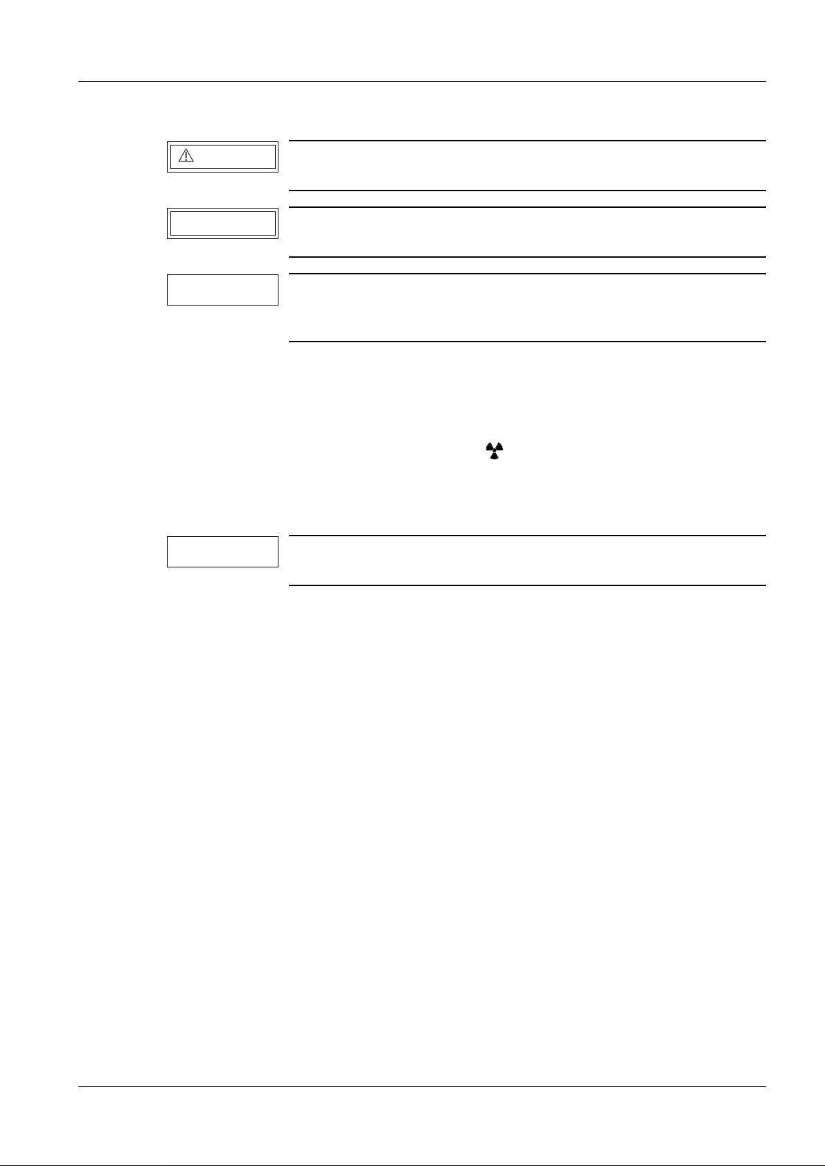
WARNING
CAUTION
NOTICE
NOTICE
Connecting the Service PC 1
Text Emphasis 1
"Warnings" are information prov ided with spec ial emphasis when
there is the potential for personal inj ury to the oper ator or patie nt .
"Cautions" are information provided with special emphasis when
there is th e p o tential for da mage to the equ i pment.
"Notices" a r e informatio n provided wi th speci al emph asis t o facilitate proper use of the equipment or proper execution of a procedure.
Safety-technical Information 1
• The safety information RA0-000.012... fi led in the system manual must be adhered to.
• Checks and adjustments that must be performed under radiation are labeled in the
inst ructio ns with t he radia tion war ning sy mbol . Take th e appropr iate r adiati on
protective measures while performing them (refer to ARTD 002.731.02...).
1 - 1
Prer equisites an d Remarks 1
For the tools and test equipment required, refer to the respective
LITHOSTAR Multiline Start-up Instructions...
• Prerequisites for co nfiguring th e system using th e Service PC are:
- Basic knowle dge such as PC handli ng and op eratio n of the Win dows pr ogram.
- Servi ce P C, s ee A RTD-0 01.719 .06. 04. 02.
- Completion of the POLYDOROS SX 65/80 "RXP 231" training course
• The service softwa re diskettes a re included in the delive ry (system manual) .
• Programming the options:
POLYDOROS SX 65/80
-80 kW
- Fluoroscopy
- Data pr inter
is permitted only if the respective license is in effect.
The license is supplied along with the BZ order form and is filed in the system manual.
Siemens AG RXL2-120.034.05 Page 1 of 4 LITHOSTAR Multiline
Medical Engineer ing Rev . 02 12.99 TD PS 24 System Manual
Page 6
1 - 2 Connecting the Service PC
Legend 1
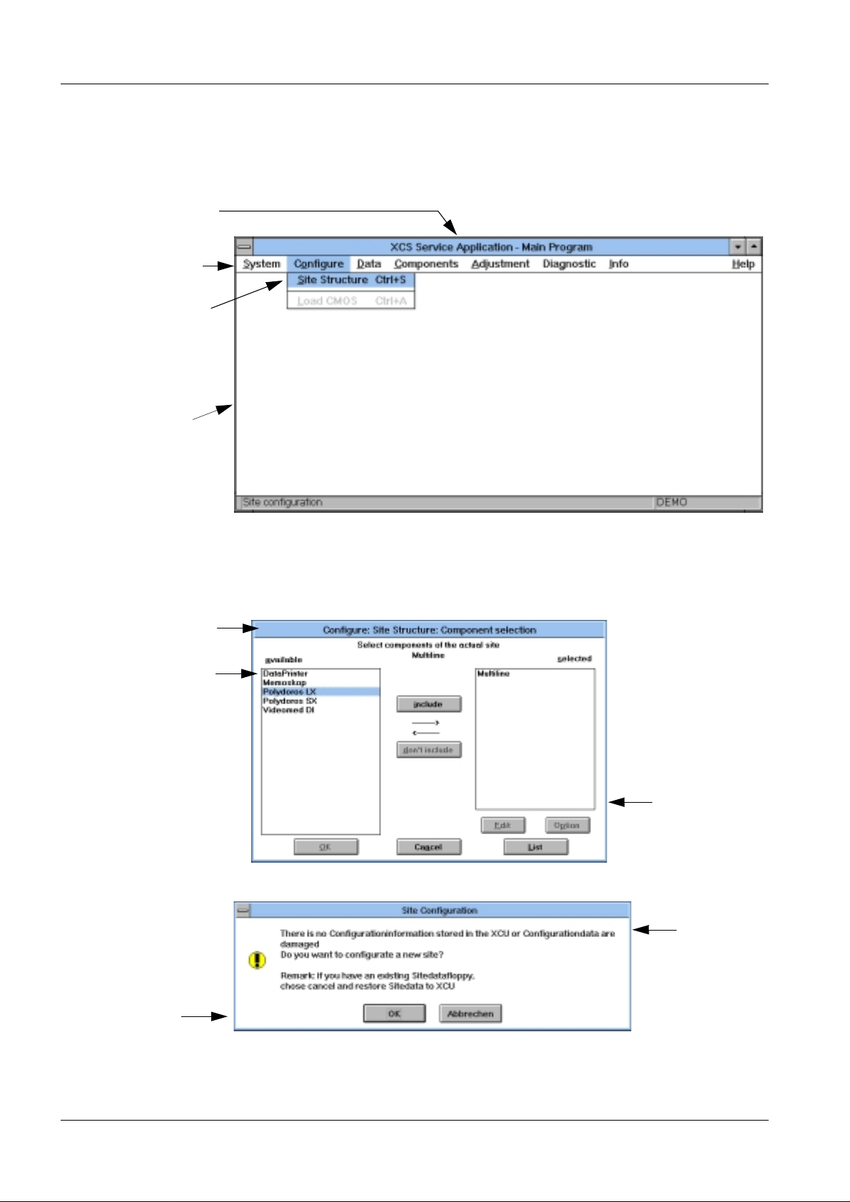
Example of Text Descriptions: 1
Window name
Main menu
Submenu
Window
• Select components in the "available" field located in the "Configure:Site
Structure:Component selection" window.
Window name
Field
Window
Window
Message
window
• Exit th e window w ith OK.
LITHOSTAR Multiline RXL2-120.034.05 Page 2 of 4 Siemens AG
System Manual Rev . 02 12.99 TD PS 24 Medical Engineer ing
Page 7
Connecting the Service PC 1 - 3
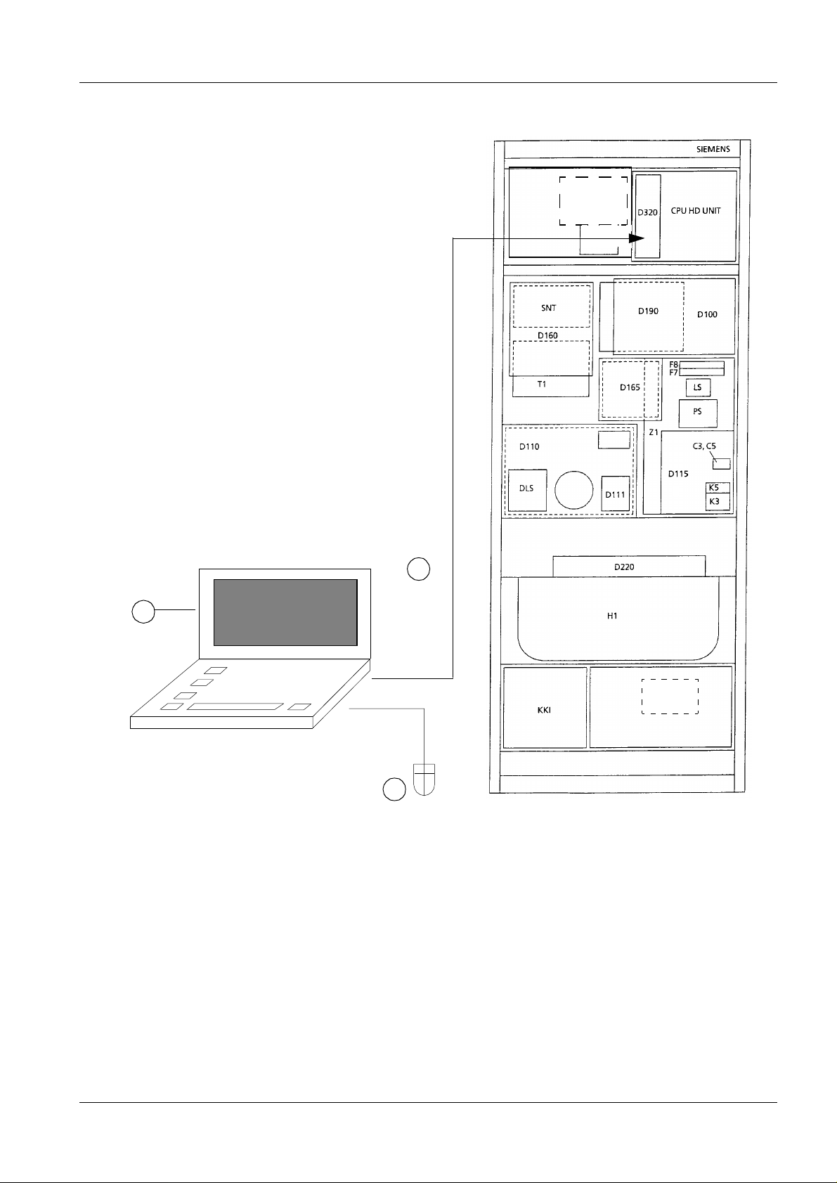
POLYDOROS SX 65/80 1
D320.XCU
to Com.1
3
M9
DIA
1
BUS mouse
Important:
- Connect the system controller
(D320.XCS) to Com 1.
- Connect the PC mouse to the PC
BUS mouse connector.
T2
M16
2
Siemens AG RXL2-120.034.05 Page 3 of 4 LITHOSTAR Multiline
Medical Engineer ing Rev . 02 12.99 TD PS 24 System Manual
Page 8
1 - 4 Connecting the Service PC
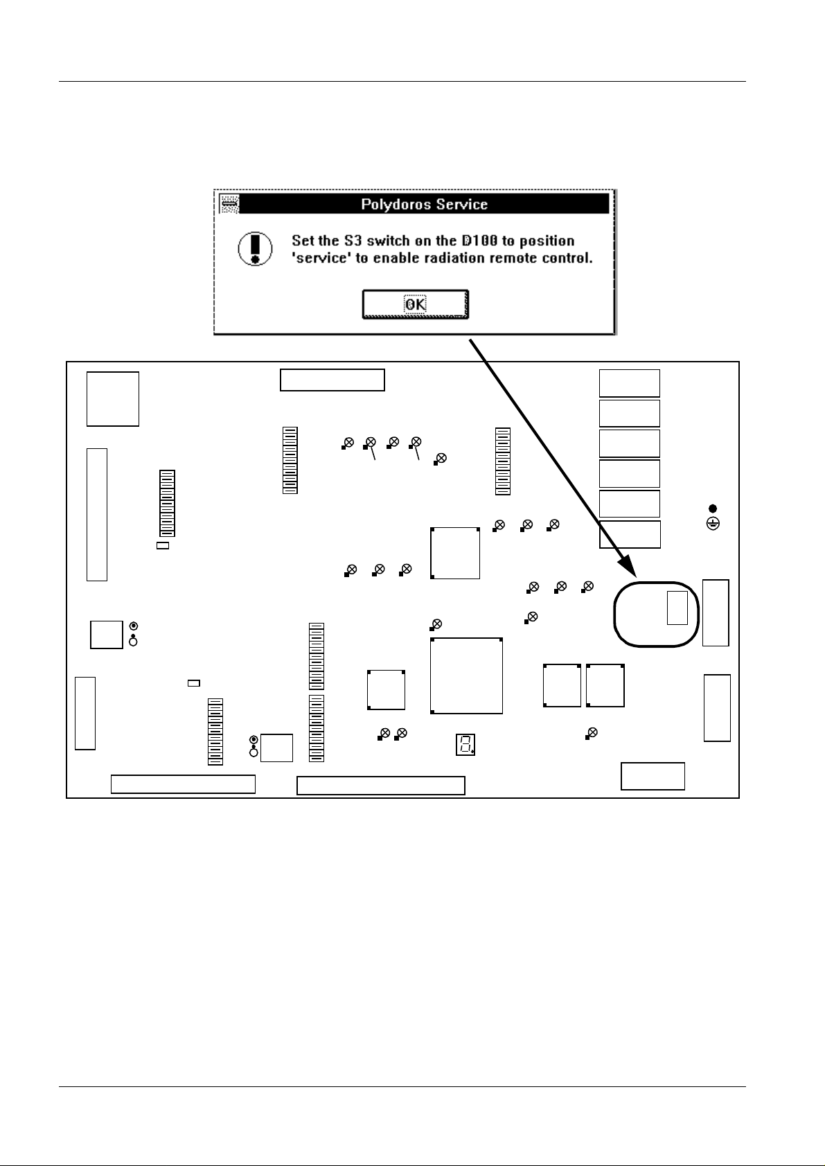
Setting the S3 switch on D100 for POLYDOROS Service
1
9
10
X50
3
12
1
3940
X5
2
2
ZK
X13
S2
Adjustment
1
10
X61
KV+
KVKV IST
KV_A
KV SOLL
A GND
R371
ZK
X1
2
1
R11
X60
OUT A
OUT B
I_ANL
GND
40
39
25
26
X64
D100
SS
S1
MA
V MAS
F MAS
CNT
SWR
GND
SS
2
1
X19
V168 V167 V166
KVMAX+
V95
AP III
ILAST
IFAH
IKOR
RAM
KVREG
WR_AUS
AN 0
AN 1
AN 2
AN 3
AN 4
AN 5
X65
1
2
KVMAX-
V94 V93
AP II AP I
V36
ROT
KVMIN+
KVMIN-
J17
V35
KURZ_AN
X20
V165
V164
WR AUS
J58
V74
XRAY
50
49
J16
V14
DL IN
UDL
DL IST
VION
FION
A GND
X63
V137 V136
V138
ION
ION
AP 1
AP 0
DOM III
V113 V110 V108
V90
ION
AP 2
DOM II
SWR HW
J15 J8
A
B
C
D
E
F
V29
M
R
M
R
M
R
P
M
R
P
M
R
P
M
R
DOM I
125V_FL
AP
B
C
AP
B
C
AP
B
C
A
B
C
A
B
C
A
B
C
NORMAL
SERVICE
X2
5
916
X3
X3
X3
X3
X2
X2
1
2
S3(X44)
X4
X41
1
5
X40
1
5
1
6
9
6
9
LITHOSTAR Multiline RXL2-120.034.05 Page 4 of 4 Siemens AG
System Manual Rev . 02 12.99 TD PS 24 Medical Engineer ing
Page 9
NOTICE
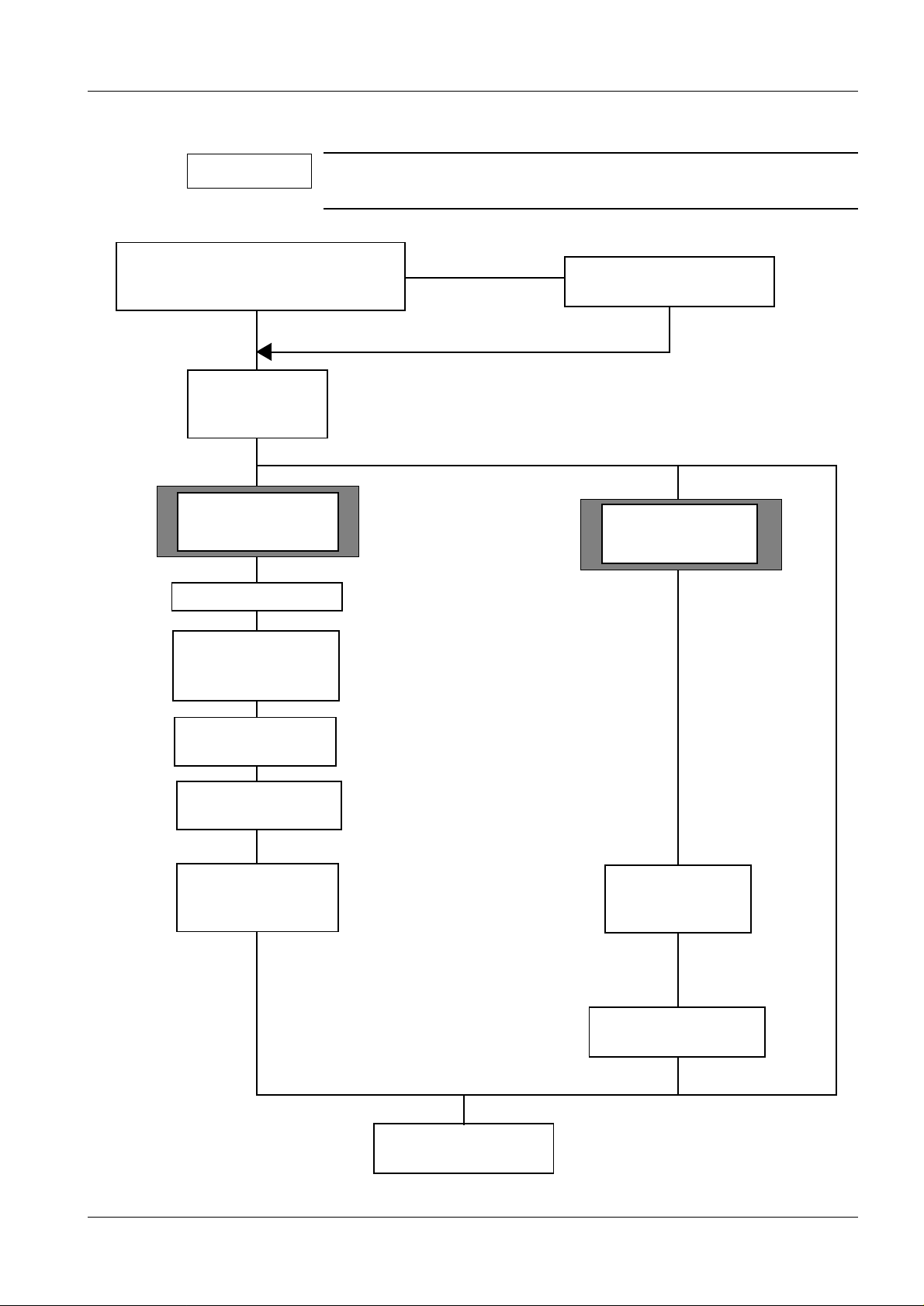
Flowchart for System Configuration 2
This flowchart is intended as a roadmap only. System configuration should be performed according to the chapters listed below.
2 - 1
Is the correct service software (SSW)
for the generator loaded on the
Service PC?
Yes
XCS service
prog ram on the
Chap.3
PC
System shipment
Subsystem shipment
and for Service
Chap.4
Chap.5
System Configuration
Basic settings
Generator parameters
IONTOMAT
No
Decide on program use
Configure X-ray tube (test shots)
mAs Relay
Install the service software
(SSW) on the Service PC
Software update
(download XCU)
Chap.3
Chap.6
Chap.7
Chap.7
Fluoroscopy
Settings
Polydoros Service
Diagnostics
Saving the data
on diskette
(back-up)
Important:
Back-up is mandatory. The
back-up diskette must be of
the latest version, otherwise
the entire system configuration has to be performed.
Exit system configuration (System/Quit)
Save the data on
a diskette
(backup)
Download (load software
onto generator)
Chap.9
Chap.7
Chap.8
Siemens AG RXL2-120.034.05 Page 1 of 2 LITHOSTAR Multiline
Medical Engineer ing Rev . 02 12.99 TD PS 24 System Manual
Page 10
2 - 2 Flowchart for System Configuration
NOTICE
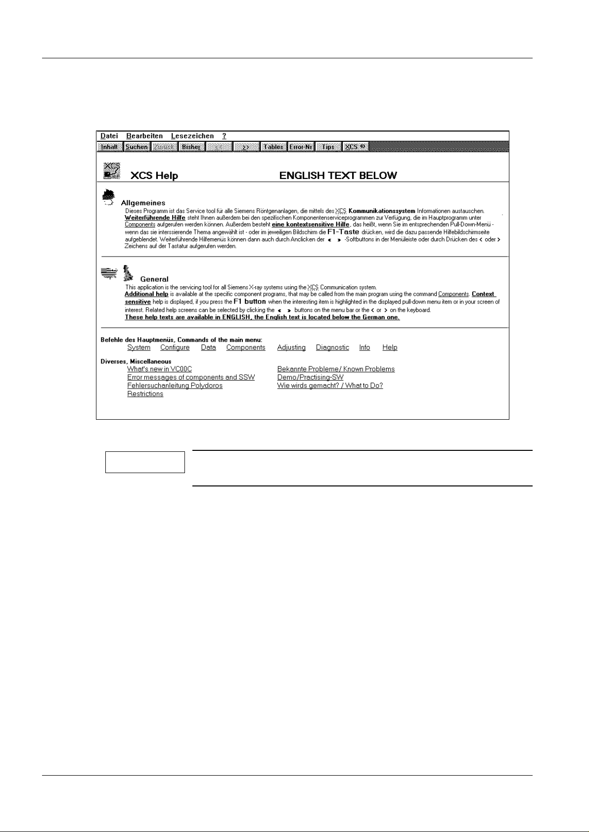
Help Text
• Select "Help/Index" in the main menu.
A help text can be called up for every active window by pressing
the F1 ke y.
LITHOSTAR Multiline RXL2-120.034.05 Page 2 of 2 Siemens AG
System Manual Rev . 02 12.99 TD PS 24 Medical Engineer ing
Page 11
CAUTION
NOTICE
NOTICE
Installing Service Software on the Service PC 3
Installing the XCS-Service Software on the Service PC 3
Do not overwrite the old "C:\SSW\XCS-Serv" directory, erase it.
Install ati o n is car r i ed o u t au to matically.
• Insert the SSW diskette 1+ into the A: drive.
• Select the File Manager in Windows.
• Select / perform the "File" menu.
• In the "command li ne", enter A:\install and confirm with OK.
• Confirm the message window with OK.
- A prompt to insert the corresponding diskette will appear.
• Confirm the following window with OK.
• The software will then create t he SERVICE program group.
C:\ SSW is preprogrammed. Do not modify it.
3 - 1
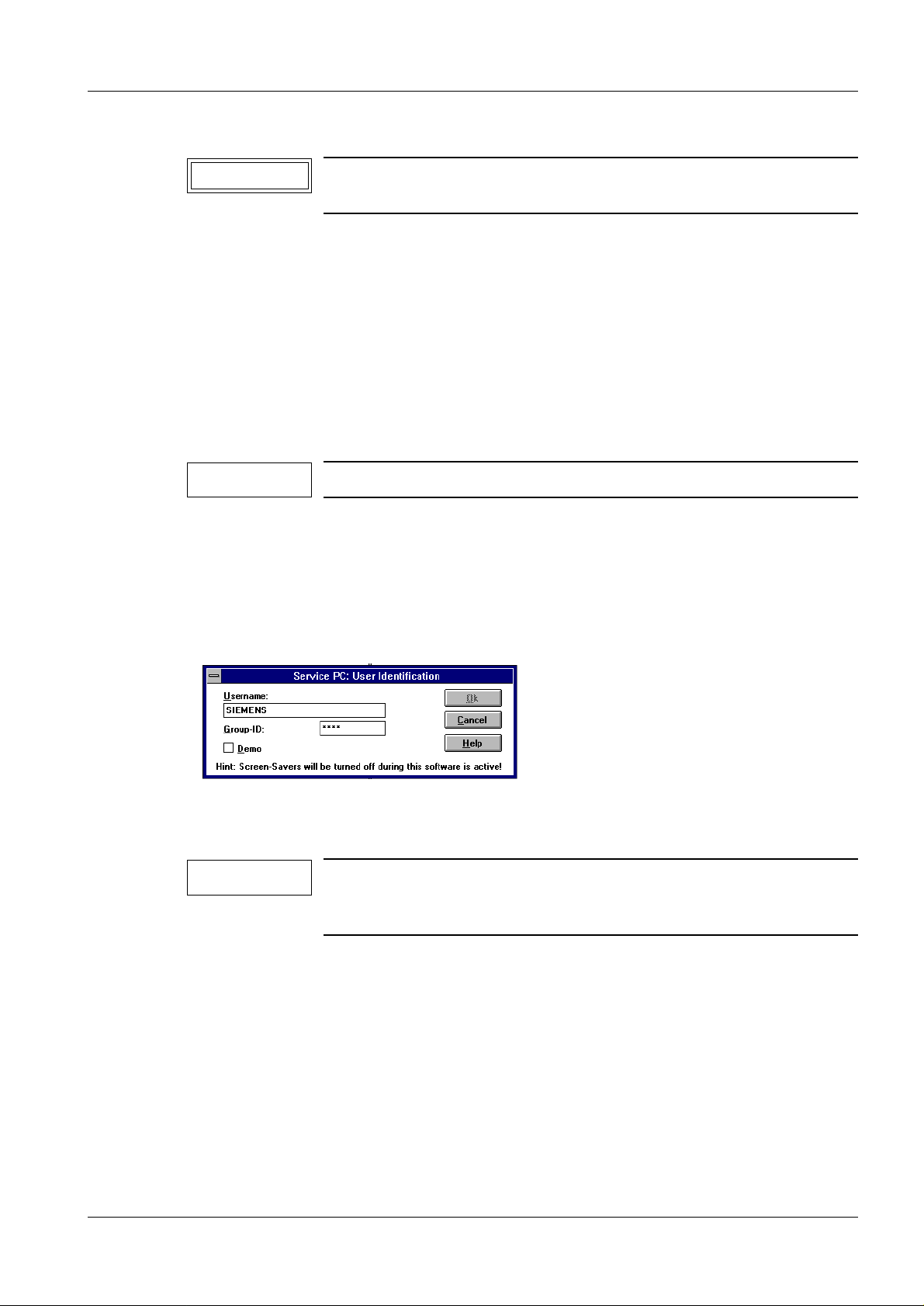
Selecting the XCS Service Program 3
• Select the Program Manager (i f not dis playe d).
• Double click the XCS-SERVICE pictogram ( icon) to select it.
• Enter the user name : Name.
• Enter the Group ID: "_siemens".
If "Demo" is checked off, the software can work without the XCU.
In the "Demo func ti on", communication wit h t he X CU is not possible.
• Exit th e window w ith OK.
Siemens AG RXL2-120.034.05 Page 1 of 2 LITHOSTAR Multiline
Medical Engineer ing Rev . 02 12.99 TD PS 24 System Manual
Page 12
3 - 2 Installing Service Software on the Service PC
NOTICE
NOTICE
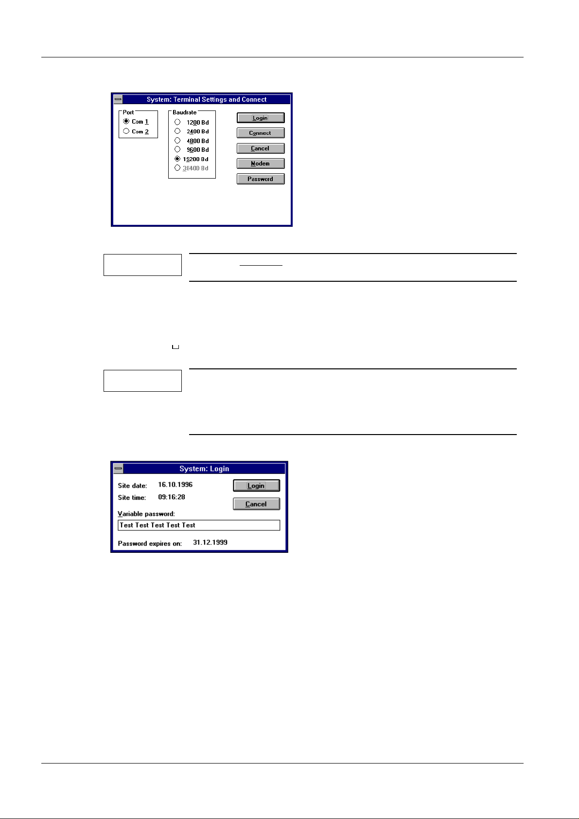
- When Connect
(clock time for the XCU) and ID code are enabled.
is sele cted in the "Syste m" menu, R ealtime CI
• Exit th e window w ith Login.
(The connection to the XCU is established when Login is s electe d.)
• If communication problems occur during “Log in”, Windows must be started from DOS
using C:Win /3.
- Set the baud rate from 19200 to 9600 and repeat the Login.
A help text can be obtained for ever y act iv e window by pr essing
the F1 ke y.
If the password field is e mpty, obtain the password from the last
Speed info with the title "P assword Sp eed info".
LITHOSTAR Multiline RXL2-120.034.05 Page 2 of 2 Siemens AG
System Manual Rev . 02 12.99 TD PS 24 Medical Engineer ing
Page 13

NOTICE
System Configuration 4
POLYDOROS SX 4
4 - 1
The reference numbers "1" through "n"
individual work steps.
indicate the sequence of
1
2
3
This window appears only if there is no co nf iguration pres ent in the XCU .
(The display on D100 indicates "2").
Exit the window with OK.
System selection
Help texts for configuration are available by pressing the F1 key.
If a system-tested system has crashed, download the configuration from the back-up
floppy. Use the "Data Restore" menu.
Siemens AG RXL2-120.034.05 Page 1 of 12 LITHOSTAR Multiline
Medical Engineer ing Rev . 02 12.99 TD PS 24 System Manual
Page 14

4 - 2 System Configuration
4
5
6
7
8
9
10
LITHOSTAR Multiline RXL2-120.034.05 Page 2 of 12 Siemens AG
System Manual Rev . 02 12.99 TD PS 24 Medical Engineer ing
Page 15

System Configuration 4 - 3
11
65 kW
12
13
available
14
15
16
*
* Text differs depending on the software version.
Check the additional opt ions and chan ge, if necessary
Additional options Default
planiio nt omat not avai lable
max tubecurrent limitation 800 mA
max mAs limitation 800 mAs
SID Tracking not available
SDM Flip not available
max tubecurrent < 100 ms 1000 mA at VD02A
800 mA at VE00J
Siemens AG RXL2-120.034.05 Page 3 of 12 LITHOSTAR Multiline
Medical Engineer ing Rev . 02 12.99 TD PS 24 System Manual
Page 16

4 - 4 System Configuration
17
18
19
no
21
22
20
The configuration will be interupted unless all necessary components are selected.
LITHOSTAR Multiline RXL2-120.034.05 Page 4 of 12 Siemens AG
System Manual Rev . 02 12.99 TD PS 24 Medical Engineer ing
Page 17

System Configuration 4 - 5
25
23
24
*
* Location of the symbols varies depending on softw are version.
Siemens AG RXL2-120.034.05 Page 5 of 12 LITHOSTAR Multiline
Medical Engineer ing Rev . 02 12.99 TD PS 24 System Manual
Page 18

4 - 6 System Configuration
26
Select
"Multiline"
28
27
Select
"Opitop
150/40/80/HC-10xL"
29
*
30
Select
"Multiline
Memoskop"
31
Select
"SDM (spotfilm)"
35
Click on "F"
32
33
*
34
* Depending on the SW version, additional symbols are available in the form.
LITHOSTAR Multiline RXL2-120.034.05 Page 6 of 12 Siemens AG
System Manual Rev . 02 12.99 TD PS 24 Medical Engineer ing
Page 19

System Configuration 4 - 7
NOTICE
33 cm HDR
36
37
41
*
Max. fluoro time until alarm:
(only VD 02A )
Max. fluoro time until blocking:
(only VD 02A )
Max. fluoro time for one patient:
(only VD 02A )
Cumulated Fluoro time until alarm:
(only VE00J)
Max. fluoro time without interrupt:
(only VE00J)
38 a..c
39
Set according to country-specifi c regulations,
e.g. BRD 4.5 min.; GB 9.5 m in.
When sho uld FL be shut dow n without
buzzer de ac t iv at ion? e.g. BRD 5 m in. ;
GB 10 min.
When should FL be shut down completely? (
Set according to country-specifi c regulations,
no shutdo w n - only alarm
10.0; disabled
e.g. s hutdo w n after 10 mi n. continuous flu oroscopy
(37 a)
(37 b)
37 c)
*
40
Dose Rate Fluoro, Dose Rate DFR und Dose rate can be edited:
If you wish to set different dose values in zoom mode, you must
adjust the zoom ratios accordingly.
* Depend ing on the software version , different symbol s a re av ailable.
Siemens AG RXL2-120.034.05 Page 7 of 12 LITHOSTAR Multiline
Medical Engineer ing Rev . 02 12.99 TD PS 24 System Manual
Page 20

4 - 8 System Configuration
If the adjacent message appears when
selecting a fluoro curve, click on OK.
Select
"Antiisowatt"
43
42
45
(not with
VE00J)
• The "Mode Selection" field varies depending on the software.
With VE00J, "Normal Fluoro" is designated "Cont. Fluoro".
44
Enter
Enter
44
"113"
"113"
(not with
VE00J)
Select
"Litho 63 KV"
46
47
Enter
"113"
(not with
VE00J)
LITHOSTAR Multiline RXL2-120.034.05 Page 8 of 12 Siemens AG
System Manual Rev . 02 12.99 TD PS 24 Medical Engineer ing
Page 21

System Configuration 4 - 9
Select
Litho 63 kV HK
50
49
48
51
Enter
"113"
(not with
VE00J)
54 52
53
Siemens AG RXL2-120.034.05 Page 9 of 12 LITHOSTAR Multiline
Medical Engineer ing Rev . 02 12.99 TD PS 24 System Manual
Page 22

4 - 10 System Configuration
59
58
Enter "0"
55
70
73
Notice:
For more info, refer to 4-12
Notice
Refer to 4-11
72
56
57
60
61
Enter
"Region 1"
Remove the back-up diskette for POLYDOROS LX from Register 10 of the logbook
and insert it in th e disk drive of the service PC .
*
62
Enter
"Org an 1 "
**
Text va ries depending on t he software ve rs ion.
*
** Depending on th e s of t w are version, additional symbols are v is ible.
LITHOSTAR Multiline RXL2-120.034.05 Page 10 of 12 Siemens AG
System Manual Rev . 02 12.99 TD PS 24 Medical Engineer ing
Page 23

System Configur ation 4 - 11
63
64
Enter
"Region 1"
69
Notice:
For more information re-
*
66
65
67
Enter
"Organ 1"
68
71
Notice:
For more see 4-10
*
* Depend ing on the software version , th e te x t and symbols ar e arranged differ ently in this field.
Siemens AG RXL2-120.034.05 Page 11 of 12 LITHOSTAR Multiline
Medical Engineer ing Rev . 02 12.99 TD PS 24 System Manual
Page 24

4 - 12 System Configuration
74
75
76
77
79
6WDUWXS
78
Working on: ......................
Enter free ly se lec t able text here, e. g. “Start-up”.
This can be read out in the “Main Program / Info”.
80
LITHOSTAR Multiline RXL2-120.034.05 Page 12 of 12 Siemens AG
System Manual Rev . 02 12.99 TD PS 24 Medical Engineer ing
Generator OFF / ON
Page 25

NOTICE
CAUTION
NOTICE
Basic Settings 5
5 - 1
- For pre-staged s
ter need to be performed:
1. Iontomat sensitivity
2. Voltage Response Corr
- A help text can be selected for every active window by pressing the F1 key.
ystems, only the following points in this chap-
• Select Polydoros .. in the "XCS Service Application-Main Program\Components\
window".
• Set the S3 (X44) switch on D100 to Service (for illustration, refer to page 1-4).
• Exit t he m essag e win dow ( Ser vice swit ch D1 00.S 3) wi th OK.
Generator Parameters 5
• Select Generator Parameters in the "Polydoros .. Service\Adjustment\" window.
• Select 24 m for the hig h vol tag e cab le l ength s in the "Ge nerat or P aram eter s" wi ndow.
• Exit th e window w ith OK.
X-Ray Tube Adjustment 5
(Refer to th e M ultiline Star t- up I ns t ructions RX L2-120.034. . .)
• Select Warm UP in the "Polydoros .. Service\Adjustment\" window.
• Exit th e messag e window wi th OK.
Close the collimator and cover the I.I. with a lead apron.
• Switc h fluor o ON in th e " Warm U p" w indow . After 10 min., fl uoro sw itches of f
automatically.
• Exit th e window w ith OK.
• The adjustment points: " Pre-Heating, Filament Correction, Filament Pushcurrent" are
perfo rmed by th e softw are. Swi tch on fl uorosco py or exp osure i n the windo w unti l the
"OK Button" is active.
First the small focus and then the large focus is calibrate d (conditioned).
• Exit th e window w ith OK.
Siemens AG RXL2-120.034.05 Page 1 of 2 LITHOSTAR Multiline
Medical Engineer ing Rev . 02 12.99 TD PS 24 System Manual
Page 26

5 - 2 Basic Settings
NOTICE
NOTICE
mAs Relay Adjustment 5
• Select mAs Relay Adjust in the "Polydoros .. Service\Adjustment\" window.
• Connect the mAs meter to D220.X16 (mAs test socket).
• Exit th e messag e window wi th OK..
Perform the mAs relay adjustment:
1. During startup
2. After replacing the D100
3. If there are deviations in mAs values in "mAs Mode".
• Select "Exposure ON".
• Enter the value measured on the mAS-meter in "Measured value: ..." using the ar row
keys.
• Exit th e window w ith OK.
• Disco nnect the mAs meter and rein sta ll t he m As jum per .
Defau lt fo r SDM 5
(For the inst ant stored im age option only, Item No. 47 82 517 J1042)
• Select the "Polydor os .. -Service /Adjustment/Iont omat Sensitivity" wind ow.
Program + 1.3 (default for SDM)
• Exit th e window w ith OK.
The data may be updated in the XCU with "Transfer Value"
allowing test exposures to be made without exiting the service
software window.
LITHOSTAR Multiline RXL2-120.034.05 Page 2 of 2 Siemens AG
System Manual Rev . 02 12.99 TD PS 24 Medical Engineer ing
Page 27

Fluoroscopy Settings 6
Fluoroscopy Dose Rate 6
Basic remarks pertaining to measurement of dose or dose rate at image intensifier
workstations
6 - 1
To determine the dose at the I.I. input (K
) or the dose rate at the I.I. inpu t ( ), center the
B
K
B
dose measurement chamber in the beam and as close as possible to the I.I.; if the system
is equipped with a spotfilm device, place it in the cassette slot.
If this is not possible, measure the dose (KTg) or the dos e rate ( ) bef ore the attenuat -
K
Tg
ing elements:
- With OT units, on the tabletop
- With UT units, on the back wall of the spotfilm device
- With C-Arm units, on the grid
The value at th e I .I. input is calcula te d us ing the corre c ti on f ac t or m (equipm ent
attenuation factor).
The equipment attenuation factor comprises all attenuating elements located between the
patient an d t he image rece pt or including t he distance fa ctor; the factor is lis t ed in the
equipment test protocols. It can also be calculated by multiplying the attenuation factors of
all the indiv idual element s .
In additio n, fa c to r in a radiation at te nuation of 6% fo r th e dose measurement chamber
(fac t or 0.94 ).
Determining Dose/Dose Rate directly at the I.I. Input 6
Dose Rate
;
K
K
B
Bg
0,94×=
Measurement chamber in I.I.
plane
Dose
K
B
K
0,94×=
Bg
Measurement chamber in
front
K
K
Tg 0,94×
----------------------------=
B
m
;
K
K
Tg 0,94×
----------------------------=
B
m
Exception 1: Dose rate measurement when the ADC measurement field is larger
than the d o se measurem ent chamber:
Allow ADC to adjust to 2.1 mm Cu filtration. Press STOP , then place the dose measuremen t ch am ber into the be am and measure the dose rat e.
In this instance, the fact or 0.94 should not be used.
Excepti o n 2: D o se measure ment when th e d o minant is lar g er t h an th e dose measureme n t ch amber:
Insert 2.1 mm Cu and place the dose measurement chamber in the beam. Trigger an
exposur e and measur e th e dose (K
or KTg) and the m As v alue (Qg1). Remove the
Bg
dosimeter from the beam, trigger an exposure a nd measure the mAs value (Qg2).
Calculate the dose at the I.I. input (KB) as follows:
Q
K
B
g2
---------- -×=
B
Q
g
g
1
K
;
B
K
Tg
----------m
Q
g2
-----------×=K
Q
g
1
Siemens AG RXL2-120.034.05 Page 1 of 4 LITHOSTAR Multiline
Medical Engineer ing Rev . 02 12.99 TD PS 24 System Manual
Page 28

6 - 2 Fluoroscopy Settings
Determining the equipment attenuation factor from the individual attenuation
factors
Equipment attenuat ion factor m = m
Attenuation factor of tabletop, spotfilm device back wall, etc. m
Attenuation factor of the scatter radiation grid m
Attenua tio n f ac t or of the Iontomat chamber m
Attenuation factor from the distance factor
m
Equipment
attenuation
factor
x mR x mI x mA ......
T
T
R
I
2
r
B
----- -
=
mA
r
Cu filter
r
T
r
B
K
Tg
Measurement chamber before the attenuating
element s , tabletop or spo t fil m dev ic e back wal l,
grid
Iontomat c hamber
K
Bg
Measur ement cham ber in I.I. plan e (c as s ette
K
B
slot)
KB/ = Dose/dose rate measured directly at the I.I. input
K
B
/ = Dose/dose rate measured in the I.I. plane
K
K
Bg
Bg
/ = D ose/dose rate measured before the at t enuating elem ents
K
K
Tg
Tg
r
B
r
T
= F ocus-image receptor distance
= D istance b et w een focus and beginning of attenuating elements
Formulas to Calculate Dose/Dose Rate in th e M easureme n t Pl an e for Adjustment
of Dose/Dose Rate
For the adjustment, the dose or dose rate required directly at the I.I. input must be converted from t he measurement plane (I .I . plane or before t he attenuating element s) . For
this, use the conversion formulas:
;
;
Dose Rate
K
K
B
K
T
B
----------=
g
0,94
K
B
-------------------=
g
0,94
m×
Dose
Measurement chamber in
I.I. plane
Measurement chamber be-
K
K
fore at ten u ating elem en ts
LITHOSTAR Multiline RXL2-120.034.05 Page 2 of 4 Siemens AG
System Manual Rev . 02 12.99 TD PS 24 Medical Engineer ing
K
B
----------=
B
0,94
g
K
m×
B
-------------------=
T
g
0,94
Page 29

Fluoroscopy Settings 6 - 3
NOTICE
Remark: The radiation attenuation resulting from the dose m easuremen t ch am ber is
already taken into account during setting
(for adjus t m ent: remove the dose measurement chamber from the beam).
Do not use the factor of 0.94 for calculating the dose rate to be set.
If the dose/dose rate is being checked (not set), the factor of 0. 94 should be
taken into account.
Example for determining the correction factor
Correction factor m (tot al) =
(source-I.I. distance/source-measurement chamber distance)
2
x m-factor (Iontomat chamber) x m-factor (grid)
x m-factor (tabletop etc., if between dose measurement chamber and I.I.) etc.
- Distance correction factor (m
source-I.I. distance( rB)
source-meas. cham ber distance(rT)
- Grid correction factor (m
- IONTOMAT chamber co rrect. factor (m
- Ta bletop corre ction factor (m
) =
A
2
Example:
) = 1.7
R
)= 1.1
I
) = 1.1
T
100
92.5
2
= 1.17
When sett ing the dose/dose rate, mu lt iply the dose/ dos e rate required at the I.I.
input by the correction factors.
e.g. 174 nGy/s x (m
A
x m
R
x m
x mT)
I
174 nGy/ s x (1. 17 x 1. 7 x 1. 1 x 1. 1) =
174 nGy/ s x 2.4 = 408 nGy/s
µR=8.7 nG y )
(1
Record the correction factor m in Chapter 4.1 of the
"Test Certificate for FL and DFR/DR Systems".
The test certificate is filed in the Logbook.
Adjusting the Dose Rate 6
Refer to Chapter 6 of the Start-Up Instructions, RXL2-120.034...., for settings/tests.
For POLYDOROS SX with optional instant stored image 6
Setting the dose refer to chapter 6, Start-up instructions RXL2-120.034....
Siemens AG RXL2-120.034.05 Page 3 of 4 LITHOSTAR Multiline
Medical Engineer ing Rev . 02 12.99 TD PS 24 System Manual
Page 30

6 - 4 Fluoroscopy Settings
NOTICE
Adjusting the Maximum Skin Dose Rate 6
Perform this adjustment only in t hos e count rie s whic h mandate a
limitation of the skin dose rate.
Refer to Chapter 6 of the Start-Up Instructions, RXL2-120.034...., for settings/tests.
LITHOSTAR Multiline RXL2-120.034.05 Page 4 of 4 Siemens AG
System Manual Rev . 02 12.99 TD PS 24 Medical Engineer ing
Page 31

CAUTION
Polydoros Service Diagnostics 7
• Select Adjustment Results i n the "Pol ydoro s .. Servi ce/Di agnost ics/" w indow.
7 - 1
Siemens AG RXL2-120.034.05 Page 1 of 2 LITHOSTAR Multiline
Medical Engineer ing Rev . 02 12.99 TD PS 24 System Manual
Press the F1 key and read the help text before performing any
steps.
Page 32

7 - 2 Polydoros Service Diagnostics
You can toggle between the help text and the current window at any time using the key
combination < ALT > and < TAB >.
You can exit the help text by pressing < ALT > and < F4 >.
Supplement to the “Save to file” window:
After mak ing the selecti on, a f ile manager w indow opens up and entry of th e f ile name is
requested in the form: “max. 8 characters” err
e.g. elog01.err or elog02.err
You can save the file to the hard drive or to the diskette.
Press the "More Info" key for further information about troubleshooting.
LITHOSTAR Multiline RXL2-120.034.05 Page 2 of 2 Siemens AG
System Manual Rev . 02 12.99 TD PS 24 Medical Engineer ing
Page 33

CAUTION
Saving the Data on Diskette (Backup) 8
8 - 1
After the adjustment is complete, perform a “Back-up”
• Insert the back-up diskette in Drive A: .
• Select Backup to disk in the "XCS Service Application - Main Program/Data/" window.
.
Siemens AG RXL2-120.034.05 Page 1 of 2 LITHOSTAR Multiline
Medical Engineer ing Rev . 02 12.99 TD PS 24 System Manual
Page 34

8 - 2 Saving the Data on Diskette (Backup)
This page int entionally le ft blank.
LITHOSTAR Multiline RXL2-120.034.05 Page 2 of 2 Siemens AG
System Manual Rev . 02 12.99 TD PS 24 Medical Engineer ing
Page 35

CAUTION
WARNING
Download (Loading Software onto the Generator) 9
XCU Download POLYDOROS SX 65/80 9
The XCU (boot software) was installed at the factory.
Perform the XCU download only:
1. After modifying the software
2. After replacing the XCU
Perform the download as follows:
• Switch the generator OFF.
• Insert the download diskette in the XCU drive (in the generator, refer to Chap. 1, Page 4).
• Switch the generator ON.
• Download will be performed automatically.
• Switch the generator OFF.
• Remove th e downlo ad disk ette fr om the XCU dr ive.
9 - 1
• Switch the generator ON.
If the PC is not connected to power but is run only on a battery,
ensure th at the battery is fully char g ed (r efer to the PC O p erating
Instructions).
Prior to performing the download, the “system time” must be
identical to the PC time (refer to Chap. 3-2 “Connect”).
The download for XCU and the D220 filament heating for the generator was performed at the factory.
Perform an XCU download only after:
- modifying the software
- rep laci ng t he XCU
Perform the filament heating download only if:
- the red LED on D220 is flashing
- the so ftwar e has cras hed
A download is not necessary after the D220 is replaced.
Siemens AG RXL2-120.034.05 Page 1 of 2 LITHOSTAR Multiline
Medical Engineer ing Rev . 02 12.99 TD PS 24 System Manual
Page 36

9 - 2 Download (Loading Software onto the Generator)
Performing the XCU-Heating Download:
• Insert the downl oad di skette in the Ser vice PC.
• Select Download to Unit in the "XCS-Service Application - Main Program/Date/"
window.
• Select SX Heating in the "Data/Download select Component" window.
• Select the Start Button in t he " Data /Dow nload " wi ndow.
LITHOSTAR Multiline RXL2-120.034.05 Page 2 of 2 Siemens AG
System Manual Rev . 02 12.99 TD PS 24 Medical Engineer ing
Page 37

CAUTION
Exiting the System Configuration 10
• Select Quit in the "XCS-Service Application - Main Program/System/" window.
• Working on:
Enter the text desired, e.g. “Start-up”.
(Texts ca n be r ead o ut i n “Main Pro gram / Info”).
• Switch the generator OFF / ON.
10 - 1
Perfo r m a “Backup
” after the ad j u stment has be en co mpleted.
Siemens AG RXL2-120.034.05 Page 1 of 2 LITHOSTAR Multiline
Medical Engineer ing Rev . 02 12.99 TD PS 24 System Manual
Page 38

10 - 2 Exiting the System Configuration
This page int entionally le ft blank.
LITHOSTAR Multiline RXL2-120.034.05 Page 2 of 2 Siemens AG
System Manual Rev . 02 12.99 TD PS 24 Medical Engineer ing
Page 39

Changes to Previous Version 11
Chap. 0 Co ve r page, revision level and ta ble of contents w ere updated
Chap. 1 - 1 Prerequ is it es and Remarks :
Sentence newly included
Chap. 4 Page 4-3 * Text supplements newly included
Page 4-5 * Text newly included
Page 4-6 * Text newly included
Page 4-7 * Text newly included and text in table newly added
Page 4-8, point: Sentence newly included, text in brackets newly added
Page 4-9 Text in bra c ke t s new ly added
Page 4-1 0 * and ** text newl y in c luded
Page 4-11 * Tex t newly included
Chap. 5 - 2 Para: DIAMENTOR MS alignment..... deleted
11 - 1
TD PS 24/ Erlwein
TD SP/ M. H einlein
SMS / Iseli n
Siemens AG RXL2-120.034.05 Page 1 of 2 LITHOSTAR Multiline
Medical Engineer ing Rev . 02 12.99 TD PS 24 System Manual
Page 40

11 - 2 Changes to Previous Version
This page int entionally le ft blank.
LITHOSTAR Multiline RXL2-120.034.05 Page 2 of 2 Siemens AG
System Manual Rev . 02 12.99 TD PS 24 Medical Engineer ing
 Loading...