

Page 1

LITHOSTAR Multiline
System manual
Start-up Instructions
SP
© Siemens AG 2004
The reproduction, transmission or
use of this document or its contents
is not permitted without express
written authority. Offenders will be
liable for damages. All rights,
including rights created by patent
grant or registration of a utility
model _or_ design,_are_ reserved.
English
Print No.: RXL2-120.815.01.02.02 Doc. Gen. Date: 02.05
Replaces: RXL2-120.815.01.01.02
Page 2

0 - 2 Revision
Chapter Page Revision
all alle 02
Document revision level
The document corresponds to the version/revision level effective at the time of system delivery. Revisions to hardcopy documentation are not automatically distributed.
Please contact your local Siemens office to order current revision levels.
Disclaimer
The installation and service of equipment described herein is to be performed by qualified personnel
who are employed by Siemens or one of its affiliates or who are otherwise authorized by Siemens or
one of its affiliates to provide such services.
Assemblers and other persons who are not employed by or otherwise directly affiliated with or authorized by Siemens or one of its affiliates are directed to contact one of the local offices of Siemens or
one of its affiliates before attempting installation or service procedures.
LITHOSTAR Multiline RXL2-120.815.01 Page 2 of 4 Siemens AG
System manual Rev. 02 02.05 CS PS 24 Medical Solutions
Page 3

Contents 0 - 3
Page
1 _______Prerequisites / General Information________________________________ 1 - 1
Required documents . . . . . . . . . . . . . . . . . . . . . . . . . . . . . . . . . . 1 - 1
Required tools and measurement devices . . . . . . . . . . . . . . . . . . . . . . . 1 - 1
Important Information Regarding Start-Up . . . . . . . . . . . . . . . . . . . . . . . 1 - 2
Abbreviations and Symbols Used in these Instructions . . . . . . . . . . . . . . . . . 1 - 2
Protective Measures. . . . . . . . . . . . . . . . . . . . . . . . . . . . . . . . . . . 1 - 3
Preliminary Steps . . . . . . . . . . . . . . . . . . . . . . . . . . . . . . . . . . . . 1 - 3
POLYDOROS SX 65/80 . . . . . . . . . . . . . . . . . . . . . . . . . . . . . . . . . 1 - 5
POLYDOROS LX 30/50 . . . . . . . . . . . . . . . . . . . . . . . . . . . . . . . . . 1 - 6
2 _______General Start-Up _______________________________________________ 2 - 1
Inspection of the I.I. support. . . . . . . . . . . . . . . . . . . . . . . . . . . . . . . 2 - 1
Line Voltage and Internal Line Impedance . . . . . . . . . . . . . . . . . . . . . . . 2 - 1
Generator Start-Up . . . . . . . . . . . . . . . . . . . . . . . . . . . . . . . . . . . 2 - 3
3 _______Shock Wave System ____________________________________________ 3 - 1
Filling the Cooling System. . . . . . . . . . . . . . . . . . . . . . . . . . . . . . . . 3 - 1
Filling the Coupling Circuit. . . . . . . . . . . . . . . . . . . . . . . . . . . . . . . . 3 - 3
Shockwave Release Function . . . . . . . . . . . . . . . . . . . . . . . . . . . . . . 3 - 5
4 _______Start-Up of Multiline System _____________________________________ 4 - 1
Service Software Installation and System Programming . . . . . . . . . . . . . . . . 4 - 1
Generator Start-Up without High Voltage . . . . . . . . . . . . . . . . . . . . . . . . 4 - 2
Checking the Display on the Operating PC . . . . . . . . . . . . . . . . . . . . . 4 - 2
Checking Selection of kV and mAs . . . . . . . . . . . . . . . . . . . . . . . . . 4 - 2
Checking the Anode Starter . . . . . . . . . . . . . . . . . . . . . . . . . . . . . 4 - 2
Generator Start-Up with High Voltage. . . . . . . . . . . . . . . . . . . . . . . . . . 4 - 2
Generator Programming. . . . . . . . . . . . . . . . . . . . . . . . . . . . . . . . . 4 - 3
Setting the Time and Date. . . . . . . . . . . . . . . . . . . . . . . . . . . . . . 4 - 3
Performing test shots from the X-ray Tube . . . . . . . . . . . . . . . . . . . . . 4 - 3
Checking kV Accuracy. . . . . . . . . . . . . . . . . . . . . . . . . . . . . . . . . . 4 - 5
Exposure Indicators on the Operating PC. . . . . . . . . . . . . . . . . . . . . . . . 4 - 5
Checking the mAs Values . . . . . . . . . . . . . . . . . . . . . . . . . . . . . . . . 4 - 5
Checking the Maximum Generator Power. . . . . . . . . . . . . . . . . . . . . . . . 4 - 5
Checking the Fluoroscopy Timer . . . . . . . . . . . . . . . . . . . . . . . . . . . . 4 - 6
Checking and Adjusting the Shock Wave Head . . . . . . . . . . . . . . . . . . . . . 4 - 6
Shock Wave Pressure Test . . . . . . . . . . . . . . . . . . . . . . . . . . . . . . . 4 - 7
5 _______Exposure Geometry ____________________________________________5 - 1
Alignment of the Radiation Field Center to the Film Center. . . . . . . . . . . . . . . 5 - 1
Fluoroscopic Field Limitation (without Overframing) . . . . . . . . . . . . . . . . . . 5 - 2
6 _______Checking the Dose Rate _________________________________________6 - 1
Siemens AG RXL2-120.815.01 Page 3 of 4 LITHOSTAR Multiline
Medical Solutions Rev. 02 02.05 CS PS 24 System manual
Page 4

0 - 4 Contents
Page
General Remarks. . . . . . . . . . . . . . . . . . . . . . . . . . . . . . . . . . . . 6 - 1
Test Videomed DIM. . . . . . . . . . . . . . . . . . . . . . . . . . . . . . . . . . . 6 - 1
Flowchart . . . . . . . . . . . . . . . . . . . . . . . . . . . . . . . . . . . . . . . . 6 - 2
A. Indirect measurement of the fluoroscopic dose . . . . . . . . . . . . . . . . . . . 6 - 6
B1. Dose Rate/Iris Adjustment for POLYDOROS LX. . . . . . . . . . . . . . . . . . 6 - 6
B2. Dose Rate/Iris Adjustment for POLYDOROS SX. . . . . . . . . . . . . . . . . . 6 - 8
C. Maximum Skin Dose Rate . . . . . . . . . . . . . . . . . . . . . . . . . . . . .6 - 11
D. Setting the Water Equivalent Take Over. . . . . . . . . . . . . . . . . . . . . . .6 - 12
Preparation (measurement configuration) . . . . . . . . . . . . . . . . . . . . .6 - 12
E. Setting the maximum Skin Dose Rate. . . . . . . . . . . . . . . . . . . . . . . .6 - 12
F. DR Snapshot (optional) . . . . . . . . . . . . . . . . . . . . . . . . . . . . . . .6 - 12
Checking the dose / image . . . . . . . . . . . . . . . . . . . . . . . . . . . . .6 - 12
Dose setting for DR . . . . . . . . . . . . . . . . . . . . . . . . . . . . . . . . .6 - 13
PDA Sensor Adjustment . . . . . . . . . . . . . . . . . . . . . . . . . . . . . .6 - 14
Image brightness for DR . . . . . . . . . . . . . . . . . . . . . . . . . . . . . .6 - 16
G. Check measurement of the B signal . . . . . . . . . . . . . . . . . . . . . . . .6 - 17
H. Resolution Test . . . . . . . . . . . . . . . . . . . . . . . . . . . . . . . . . . .6 - 18
7 ______ Start-Up and Tests of the Options _________________________________7 - 1
ECG Triggering . . . . . . . . . . . . . . . . . . . . . . . . . . . . . . . . . . . . . 7 - 1
Respiratory Triggering . . . . . . . . . . . . . . . . . . . . . . . . . . . . . . . . . 7 - 1
Respiratory and ECG triggering . . . . . . . . . . . . . . . . . . . . . . . . . . . . 7 - 1
Release shock waves and check their synchronization to the pulse and respiration rates
(refer above). . . . . . . . . . . . . . . . . . . . . . . . . . . . . . . . . . . . . . . 7 - 1
DICOM Connect . . . . . . . . . . . . . . . . . . . . . . . . . . . . . . . . . . . . 7 - 1
Multispot 2000 . . . . . . . . . . . . . . . . . . . . . . . . . . . . . . . . . . . . . 7 - 2
Setting the Time on the ECG Monitor . . . . . . . . . . . . . . . . . . . . . . . . . 7 - 2
Start-up of Sonoline Adara . . . . . . . . . . . . . . . . . . . . . . . . . . . . . . . 7 - 2
8 ______ Final Steps ____________________________________________________8 - 1
Customer-specific and Country-specific Settings for the Multiline . . . . . . . . . . . 8 - 1
Back-up and Error Memory. . . . . . . . . . . . . . . . . . . . . . . . . . . . . . . 8 - 1
Final Steps . . . . . . . . . . . . . . . . . . . . . . . . . . . . . . . . . . . . . . . 8 - 1
9 ______ Changes to previous version _____________________________________9 - 1
LITHOSTAR Multiline RXL2-120.815.01 Page 4 of 4 Siemens AG
System manual Rev. 02 02.05 CS PS 24 Medical Solutions
Page 5

Prerequisites / General Information 1
Required documents 1
• Repair instructions, shock wave system RXL2-120.091.06
• Shock Wave Pressure and Position Control SPL2-120.074.01
• Operating the service software RXL2-120.113.01
• System configuration POLYDOROS LX RXL2-120.034.02
• System configuration POLYDOROS SX RXL2-120.034.05
• Adjustment instructions, shock wave head RXL2-120.071.01
• IQC software description RXD0-000.073...
• IQC software RXD0-000.037.04
• Host software parameter setting RXL2-120.032...
• Start-up instructions, SONOLINE U3 LH300.031...
• Repair instructions, ultrasound localization RXL2-120.091.10...
Required tools and measurement devices 1
• Standard Installation Tool Kit
• Service PC (see Intranet Service Laptop for CSE’s
• PC interface cable, 5 m 99 00 440 RE999
• Internal line impedance meter 84 28 104 RE999
• Oscilloscope e.g. Fluke Scope Meter 73 92 074
• Resolution test, Type 41 28 71 820 RE999
• 17 µm Cu strip (minimum contrast check) 11 67 662 G5247
• Copper filter set (10 x 0.3 mm) 44 06 120 RV090
• Copper plate, 2.1 mm 99 00 598 XE999
• ESD equipment
• Protective conductor meter 44 15 899 RV090
• Dosimeter DIADOS 97 17 612
• Digital multimeter e.g. Fluke 187 99 94 831
• mAs meter 81 60 400 RE999
• Temperature meter ± 1° C must be purchased locally
• PTU pressure tester 30 95 408 J1008
• PTU Adapter 70 41 028 J1008
1 - 1
Siemens AG RXL2-120.815.01 Page 1 of 6 LITHOSTAR Multiline
Medical Solutions Rev. 02 02.05 CS PS 24 System manual
Page 6

1 - 2 Prerequisites / General Information
Important Information Regarding Start-Up 1
p
NOTICE
NOTE
The system cabling must be complete.
The system has been preassembled to system level, programmed and also tested at the
factory (see test certificates for generator, unit and image quality measurement, filed in
the system binder). During start-up, only a few checks or tests are required to ensure that
none of the settings has changed.
The results for tests marked must be entered in the test certificate or the image quality
test protocol as indicated for the specific case.
The following tests required for the acceptance test in the Federal Republic of Germany
according to the X-Ray Ordinance, §16, or the acceptance test in the USA, were already
performed and are documented in the test certificates:
- Visual inspection of filter values - Alignment of radiation field and film center
- Collimation of fluoroscopic field - Centering of radiation field to center of monitor
- Fluoroscopy dose rate - Maximum skin dose rate
- Resolution and minimum contrast - Unit attenuation factor
- Check of kV accuracy
When performing service work and tests, adhere to the productspecific safety information in the document as well as the general
safety information contained in the ARTD/ Part 2.
The oscilloscope must always be connected to ground. Use the
TEK isolation transformer and the trigger option to avoid interference from ground loops that may distort the measurement
results.
NOTE
According to DHHS Regulations, the following items must be checked:
1. Documents required for the customer
2. Radiation protection
3. DHHS and identification labels
These measurement values and the values determined during the
start-up procedure can be taken from the test certificate and
entered in the Acceptance Test Protocol.
Abbreviations and Symbols Used in these Instructions 1
AH = Recessed Allen screws HH = Hex-head bolts
DVM = Digital Volt Meter SID = Source-to-image distance
FID = Focus - Image Intensifier Distance C = Collimator
I.I. = Image Intensifier FL = Fluoroscopy
LITHOSTAR Multiline RXL2-120.815.01 Page 2 of 6 Siemens AG
System manual Rev. 02 02.05 CS PS 24 Medical Solutions
Page 7

Prerequisites / General Information 1 - 3
Protective Measures 1
• Adhere to the protective measures contained of the LITHOSTAR Multiline System
binder.
NOTICE
WARNING
Tests and adjustments performed with radiation ON are identified
by the radiation warning symbol .
Radiation protection must be worn during these types of adjustments (refer to ARTD part 2).
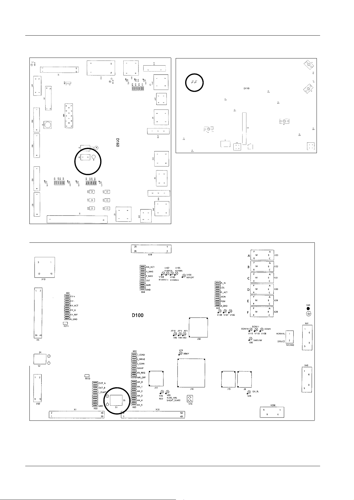
Voltage is still present in transformer T1 and power-on circuit
D160 even after the generator is switched off (see wiring diagrams X2206-10, X2169-10).
Following generator switch-off a voltage of approximately 600 V
DC is still present for the converter! LEDs V35 and V36 on D110
(Fig. 1) indicate this (X2206-16, X2169-10) and LED V89 (X2206-19,
X2168-019) lights up.
The voltage drops to 0 V in approx. 1
when the voltage reaches approximately 30 V.
1
/2 minutes; the LED’s go out
• Set the main system switch to OFF to switch off power to all components (generator and
connected equipment).
• Switch OFF (S1) SS on the D 100 board (Fig. 1, no inverter power) to avoid inadvertent
release of high voltage or radiation.
• Install or remove assemblies only with the generator switched off and according to ESD
guidelines.
Preliminary Steps 1
• Set switch (S1) on board D 100 to SS OFF (Fig. 1).
Siemens AG RXL2-120.815.01 Page 3 of 6 LITHOSTAR Multiline
Medical Solutions Rev. 02 02.05 CS PS 24 System manual
Page 8
1 - 4 Prerequisites / General Information
V36 V35
S2
D110
D160
S1
D100
Fig. 1
LITHOSTAR Multiline RXL2-120.815.01 Page 4 of 6 Siemens AG
System manual Rev. 02 02.05 CS PS 24 Medical Solutions
Page 9
Prerequisites / General Information 1 - 5
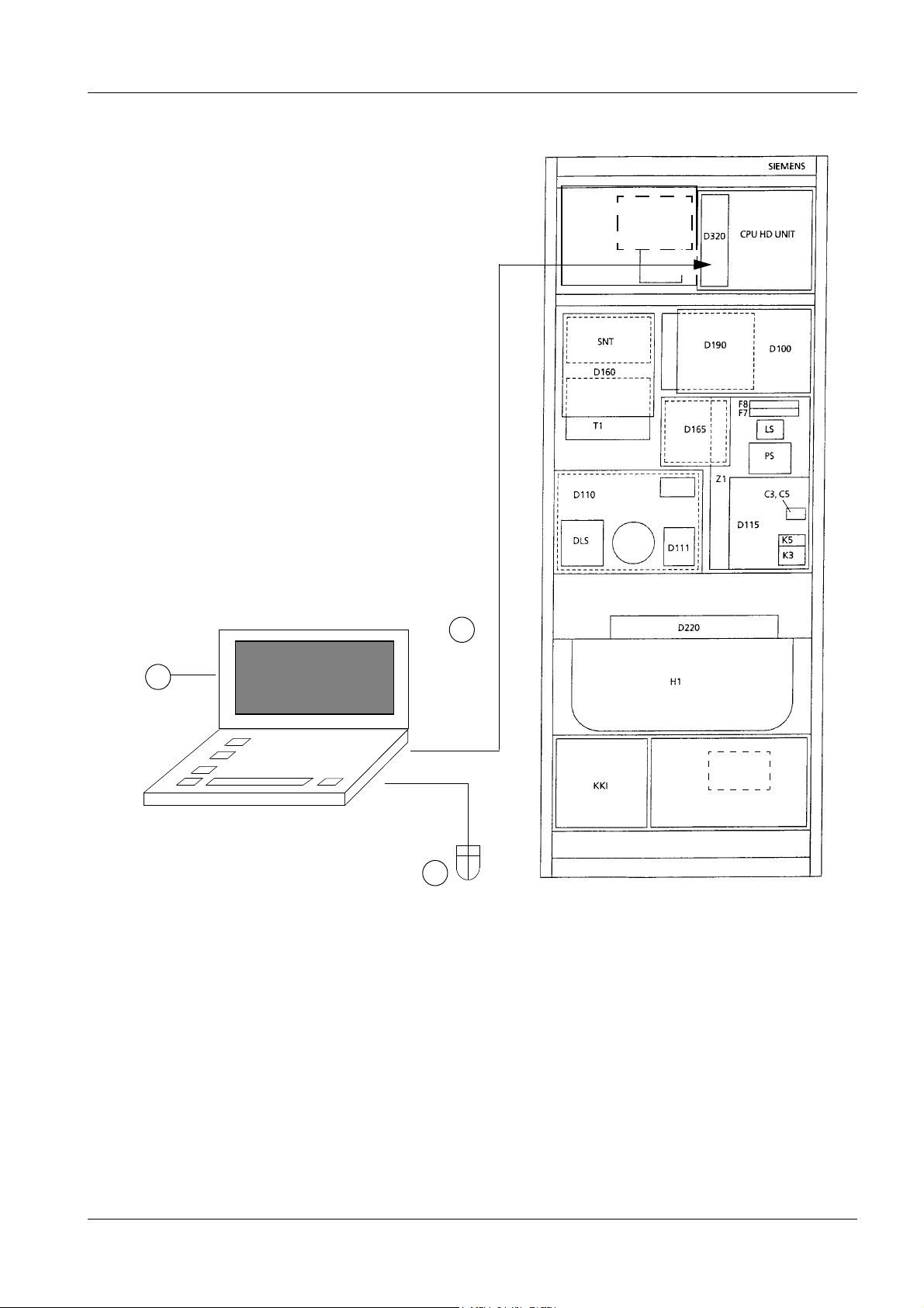
POLYDOROS SX 65/80 1
D320.XCU
to Com.1
3
M9
DIA
1
BUS mouse
Important:
- Connect the system controller
(D320.XCS) to Com 1.
- Connect the PC mouse to the PC
BUS mouse connector.
T2
M16
2
Siemens AG RXL2-120.815.01 Page 5 of 6 LITHOSTAR Multiline
Medical Solutions Rev. 02 02.05 CS PS 24 System manual
Page 10
1 - 6 Prerequisites / General Information
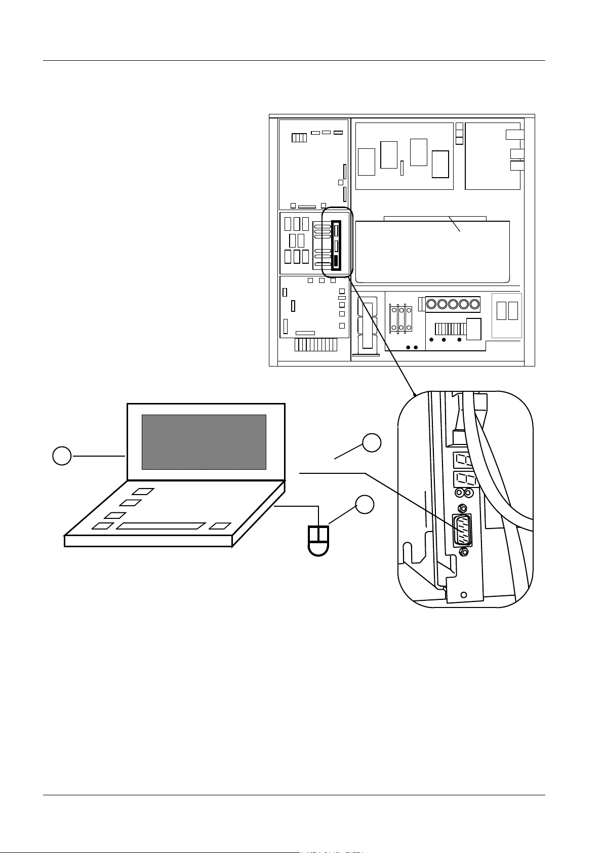
POLYDOROS LX 30/50 1
D110
D115
D100
D200
D220
K30
M16
D291
X9
SN
D160
X5
T2
H1
K20
F1F2 F3
3
1
Com 1
Com 2
2
X5
SPC
Important:
The system controller (D200.X5)
must be connected to Com 1.
LITHOSTAR Multiline RXL2-120.815.01 Page 6 of 6 Siemens AG
System manual Rev. 02 02.05 CS PS 24 Medical Solutions
Page 11
General Start-Up 2
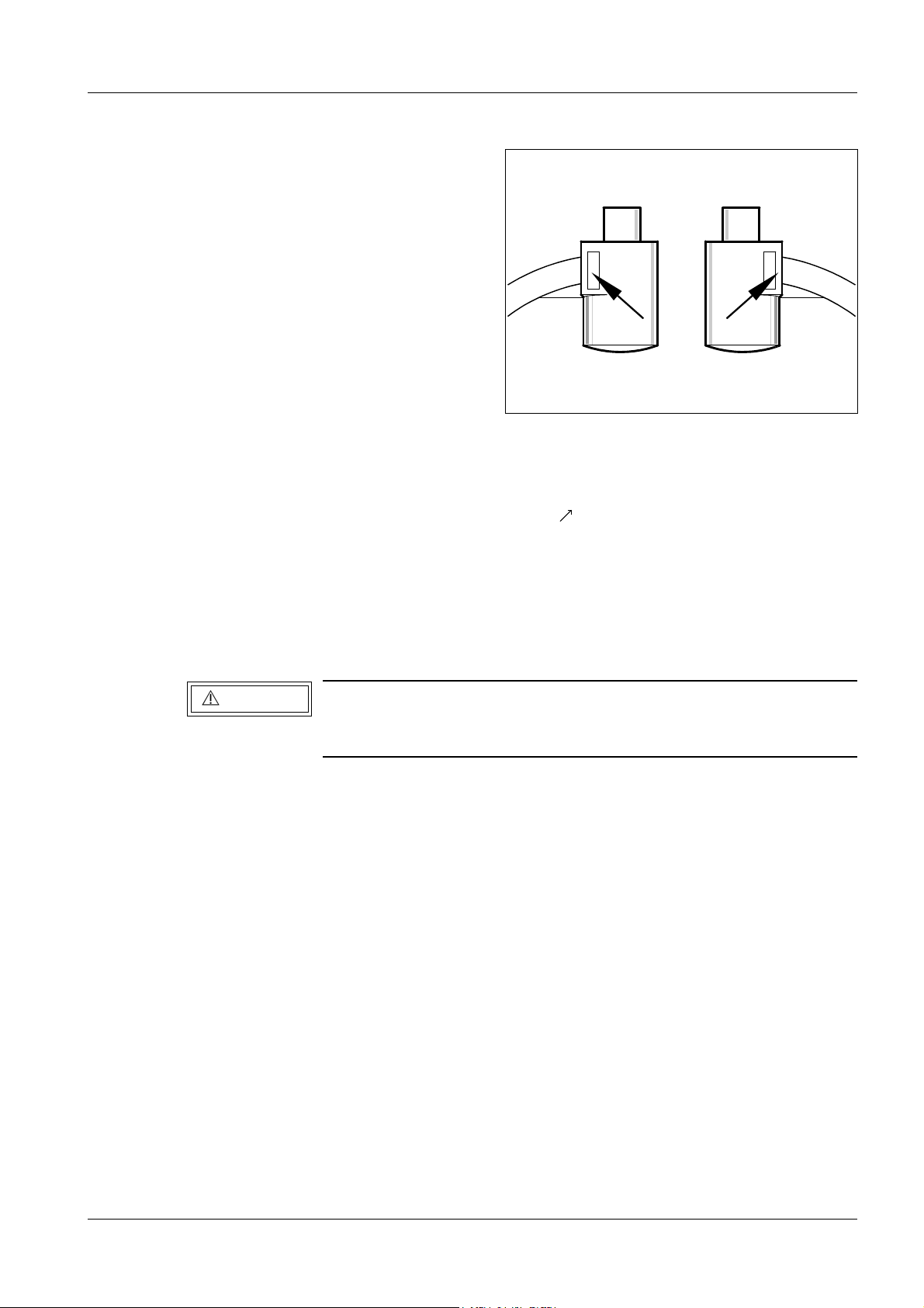
Fig. 1
Inspection of the I.I. support 2
• Remove both covers from the image intensifier ( /Fig.1).
2 - 1
p
• Check the image intensifier support for damage.
• Replace the image intensifier if defects are found.
• Reattach the covers if no defects are found.
Line Voltage and Internal Line Impedance 2
CAUTION
• Remove the cover from the knife fuses F1, F2 and F3 in M16 of the generator and
remove the fuses using the special gripper.
• Connect a multimeter between two of the phases at the lower connections of the fuse
holders for F1, F2 and F3 (X2169-11, POLYDOROS LX / X2206-10, POLYDOROS SX).
• Switch the system breaker ON.
• Use the multimeter to measure the voltage, phase to phase, consecutively.
• Record the voltage measured in the Multiline test report.
• Switch the system breaker OFF.
The LITHOSTAR Multiline system can be operated only at a line
voltage of 400 V ± 10% and 50/60 Hz. A system pretransformer
must be used for all other line voltages.
• Measure the internal line impedance at M16.L1, L2, L3 using the internal line impedance
meter (phase-to-phase) as follows:
• Connect the internal line impedance meter between 2 phases respectively of L1, L2 and
L3.
• Switch the system breaker ON.
• Perform the measurement.
Siemens AG RXL2-120.815.01 Page 1 of 4 LITHOSTAR Multiline
Medical Solutions Rev. 02 02.05 CS PS 24 System manual
Page 12
2 - 2 General Start-Up
• Switch the system breaker OFF.
• Remove the internal line impedance meter and test the other phases.
p
• Record the measured value in the table below or in the Multiline test report.
• To reach full generator power, the measured internal power line impedance may not
exceed the following value.
U
Line
400 V ± 10% 0.15 Ohm
400 V ± 10% 0.14 Ohm
400 V ± 10% 0.11 Ohm
max. R
max. R
max. R
for POLYDOROS LX 50 Measured
Line
for POLYDOROS SX 65
Line
POLYDOROS SX 80
Line
• Switch the system breaker OFF.
• Reinstall the knife fuses.
• Reinstall the cover over the knife fuses.
LITHOSTAR Multiline RXL2-120.815.01 Page 2 of 4 Siemens AG
System manual Rev. 02 02.05 CS PS 24 Medical Solutions
Page 13
General Start-Up 2 - 3
Fig. 2
Generator Start-Up 2
• Switch off circuit breakers F7, F8 and F9 in M16 of the Multiline control cabinet.
• Switch the system breaker
ON:
NOTE
In the event of a fault check the fuses for transformer T1 (below
D160) (X2169-11, 12 and 19 and X2206-11, 12 and 19).
The red LED V23 and the lamps H1 and H2 must light up
on power-on circuit board D160.
• Switch the system ON; The generator initializes; the 7-segment display on D100
displays "b" (meaning "ready").
• Use S2 on D160 to switch the generator OFF (test of blocking). It may not be possible to
switch on the generator from the control console.
• Set sliding switch S2 on D160 position 1.
• System contactor OFF.
• Switch on circuit breakers F7, F8, F9 in the M16 control cabinet.
• Switch S1 on shock wave cabinet N12 ON.
• Withdraw plug from pump M15 in N12 (pump must not run dry).
• Switch the system ON.
The message "No contact to shock wave system" appears on the PC monitor.
NOTE
Siemens AG RXL2-120.815.01 Page 3 of 4 LITHOSTAR Multiline
Medical Solutions Rev. 02 02.05 CS PS 24 System manual
Due to changes in the monitoring of the shock wave system, the
shock wave cabinet must be switched on when switching on the
system. The shock wave cabinet can be switched off, when the
system is ready for use.
Page 14

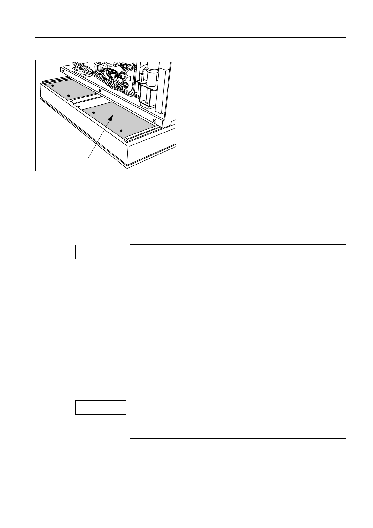
2 - 4 General Start-Up
Systems with the ultrasound option:
• Remove the front cover (Fig. 2).
• Install the uro insert.
• Move the unit to the left so that board D31 is accessible.
• Connect control cable X28 on board D31 and secure it with screws.
• Reattach the cover.
LITHOSTAR Multiline RXL2-120.815.01 Page 4 of 4 Siemens AG
System manual Rev. 02 02.05 CS PS 24 Medical Solutions
Page 15

Shock Wave System 3
Filling the Cooling System 3
3 - 1
NOTE
Due to changes in the monitoring of the shock wave system, the
shock wave cabinet must be switched on when switching on the
system. The shock wave cabinet can be switched off, when the
system is ready for use.
• Move the shock wave head into the therapy position.
• Disconnect the plug to the M15 in the N12 pump (the pump must not run without water).
• Measure the room temperature.
• Connect the multimeter at test point X2.2 of board W11 in slot W11A and connect the 0 V
lead to the D1 board at test point X3.
• Check whether the voltage measured matches the room temperature value from the
following table.
Voltage tolerance: ± 30 mV; adjustable using R13 on the W11 board.
°C18° C19° C20° C21° C22° C23° C24° C25° C26° C
Volt 4.36 4.53 4.69 4.85 5.01 5.17 5.33 5.50 5.66
° F64° F66° F68° F70° F72° F73° F75° F77° F79° F
°C27° C28° C29° C30° C31° C32° C33° C34° C35° C
Volt 5.82 5.98 6.14 6.31 6.47 6.63 6.79 6.95 7.11
° F81° F82° F84° F86° F88° F90° F91° F93° F95° F
• Turn N12 off with S1.
• Reconnect the connector to the M15 pump.
• Fill the water container with 4 liters of sterile water (refer to Speed Info RX 17/96).
• Install the water container in the cabinet on the transport bracket.
NOTE
The container should not be closed to allow adequate ventilation.
• Ensure that the vent valve on the filter is set to open. If not, set it to open by holding the
lower brass screw in place with a crescent wrench.
• Open the red cap on the vent valve.
• Open the quick couplings and pump outlet (located on the right hand-side behind the
pump).
• Turn on N12 using switch S1 until water runs out of the fast couplings.
• Turn off N12 using switch S1.
• Connect the quick couplings and the pump.
• Turn on N12 using switch S1; the cooling circuit is filled and ventilated.
NOTE
Siemens AG RXL2-120.815.01 Page 1 of 6 LITHOSTAR Multiline
Medical Solutions Rev. 02 02.05 CS PS 24 System manual
Ensure that the cooling circuit does not contain air bubbles.
Page 16
3 - 2 Shock Wave System
If the M15 pump and the Y1 valve should start to vibrate, i.e. switching on and off constantly, disconnect and reconnect the connector of the Y1 valve several times until the
M15 pump runs smoothly.
Alternately vent each circuit of the cooling unit (OT and Litho) for approx. 10 minutes to
remove the air. The flow rate can be increased to 40 l/h (W11.R5).
During venting, move the shock wave head several times from the park position into the
therapy position and back again.
• If no more air bubbles can be seen in the
flow rate meter, set R5 on board W11 to a
flow rate of 25 ± 3 liters.
(Refer to figure on the right). If necessary,
set switch S1 of the flow rate meter to
20 ltr.
• After the filling process terminates,
LED V3 on board W11 must light up.
• Check the S1 flow rate switch.
Decrease the flow rate slowly with potentiometer R5 on W11 until a flow rate of
20 ltr. is displayed. LED V3 is no longer
illuminated.
Subsequently, reset the flow rate to
25 ± 3 l .
25l
20l
After venting the system, check the voltage at measurement point X3 (or MP.X2.3) of
board W11. (0 Volts on board D1 at measurement point X3).
This voltage must not change by more than 50 mVolts within 10 minutes. The cooling unit
must be switched off during this check.
NOTE
If the voltage drops
⇒ Leakage in the cooling circuit
⇒ Solenoid valve Y1 is defective
• Tighten the red cap of the vent valve.
LITHOSTAR Multiline RXL2-120.815.01 Page 2 of 6 Siemens AG
System manual Rev. 02 02.05 CS PS 24 Medical Solutions
Page 17
Shock Wave System 3 - 3
S2
S1
S3
R71
R85
R49
R998
Fig. 1 Fig. 2
standard mode
Empty coupl. bellows
Button on: Filling coupling bellows
standard mode
Service mode
Offset Coupling pressure sensor B1
Lift min. (V 22)
Lift max. (V23)
Offset Filling level sensor W4 (B3)
W12 Board
Function in
service
mode only
M20
Filling the Coupling Circuit 3
Approximately 4 liters of distilled water are required (refer to Speed Info RX 17/96).
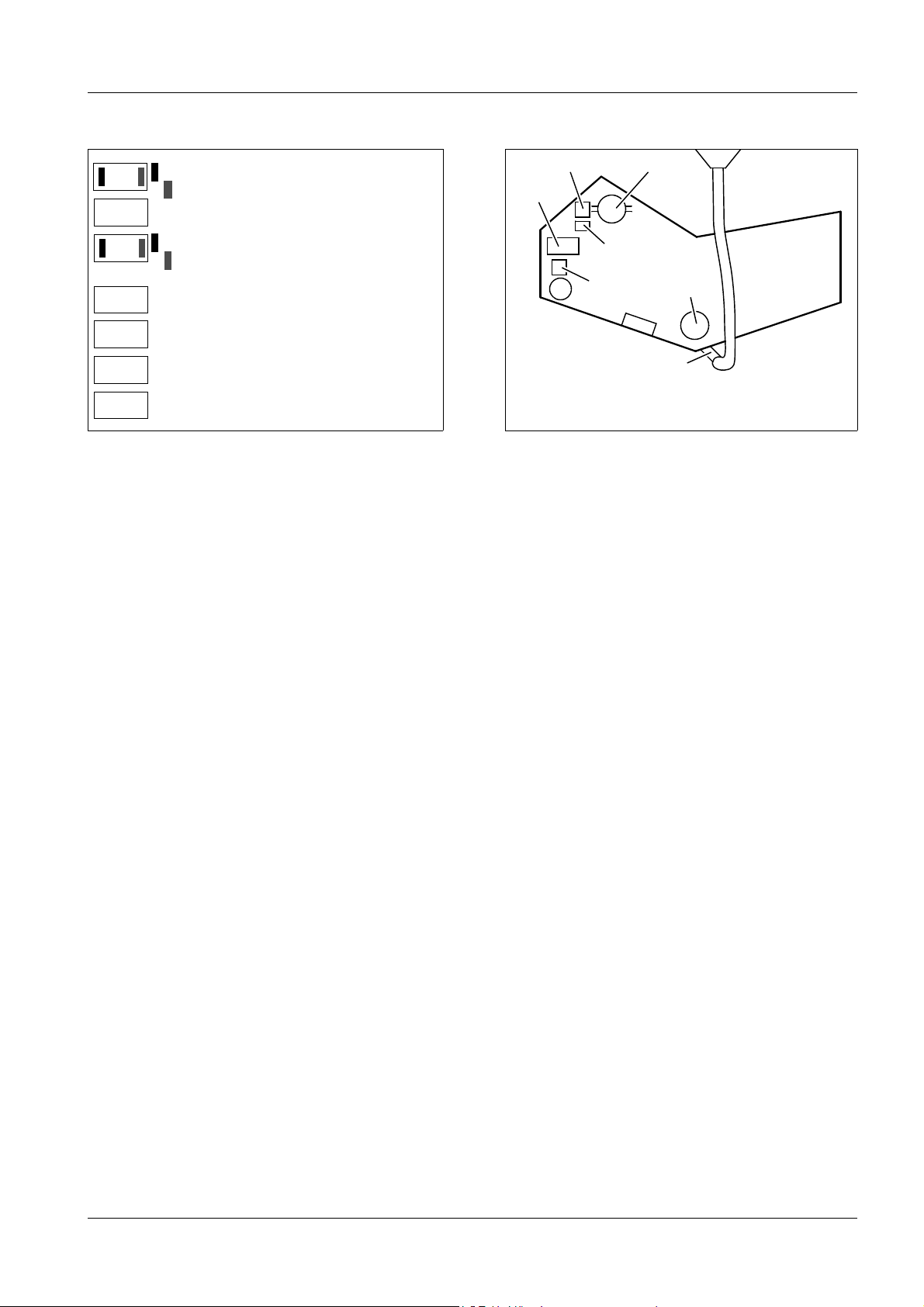
• Set the following switches on board W12 (Fig. 1):
S3 in SERVICE MODE position
S2 in EMPTY COUPL. BELLOWS position (valve Y3 open)
Y2
Y3
S5
W4 (B3)
1
3
2
• Connect the test device to board W12 at test point X3.1 and connect the 0V lead to test
point X3 on board D1.
• Check if the measured voltage of the B1 pressure meter equals1,0 V ± 0.01 V at mea-
surement point X3.1 at atmospheric pressure (adjustable with R71 on board W12).
• Measure the zero point offset of the W4 (B3) sensor on board W12 d14
(0V on board D1X3). Record the measured value (acceptable range: 1.80 V ± 0.25 V).
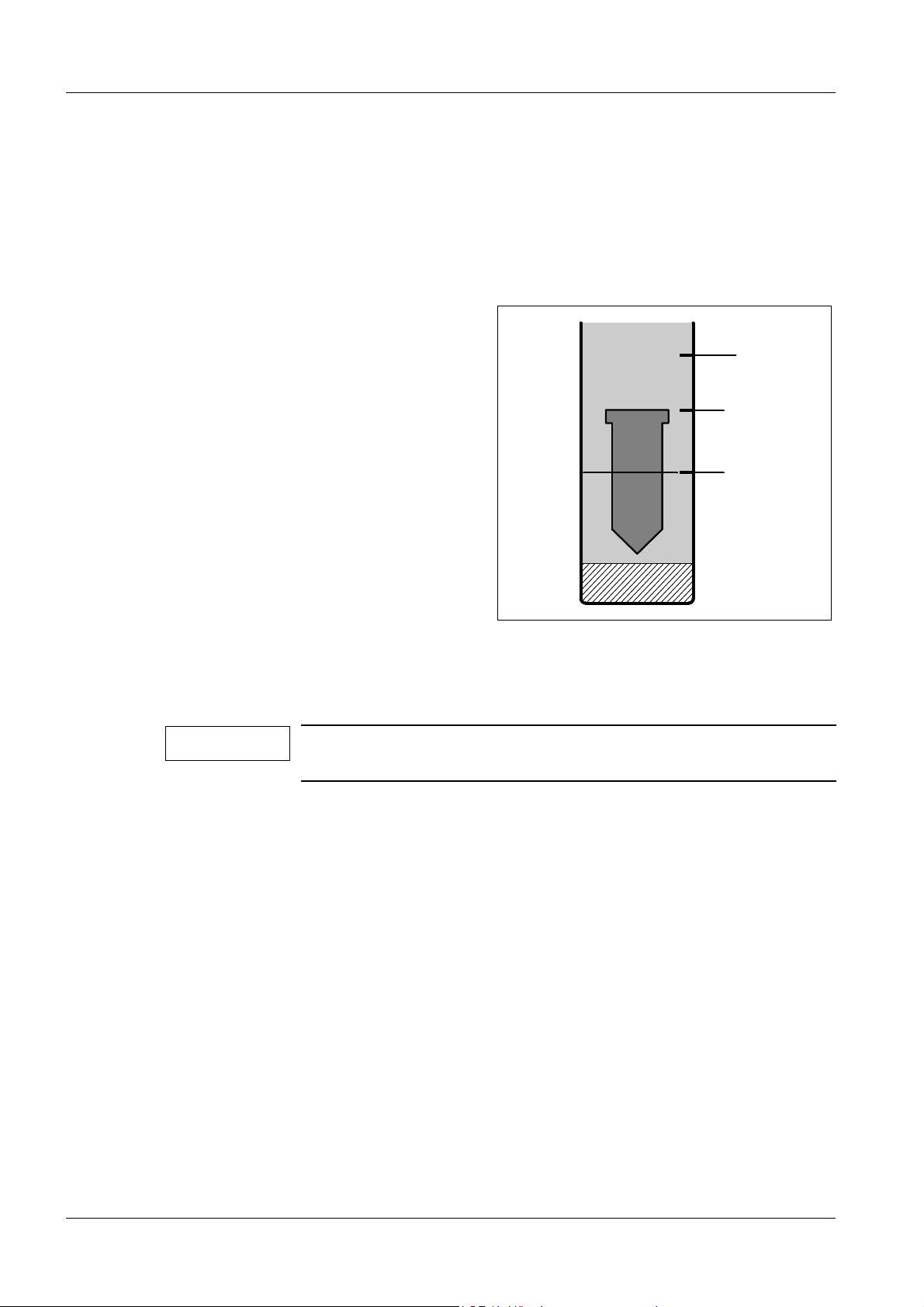
• Connect the funnel for filling the water tank (2/Fig. 2).
• Fill the water tank until the water level is between the two marks on the upper sight glass
(1/Fig. 2).
• Remove the funnel (open the quick coupling on the water tank) (2/Fig. 2).
• Remove the elbow from the coupling bellows.
• If there are air bubbles:
- Fill the hose through the elbow using a syringe and a needle.
If the hose cannot be filled, remove the shock wave head cover and fill it according to
the section "Replacing the Sensor Module" of the instructions RXL2-120.091.06..
• Press the coupling bellows together.
• Reconnect the elbow.
• Set the S2 switch (Fig. 1) to STANDARD MODE (Y3 valve closed).
Siemens AG RXL2-120.815.01 Page 3 of 6 LITHOSTAR Multiline
Medical Solutions Rev. 02 02.05 CS PS 24 System manual
Page 18

3 - 4 Shock Wave System
Fig. 3
• Fill the coupling bellows with water by activating the S1 key on board W12 (Fig. 1)
several times.
NOTICE
The level in the water tank must not drop below the mid range of
the lower sight glass (3/Fig.2).
• Remove any air that has collected in the coupling bellows using a syringe without a
needle.
• Set switch S2 to the EMPTY COUPL. BELLOWS position (Fig. 1) (valve Y3 is open).
• Connect the funnel to fill the water system (2/Fig. 2).
• Fill the water tank so that the water level is between the marks on the upper sight glass
(1/Fig. 2).
NOTICE
Fill the water tank only when the coupling bellows has completely
collapsed (a minimal amount of water remains in the coupling bellows).
• Remove the funnel (release the quick-connector on the water tank) (2/Fig. 2).
• Set the S2 switch on board W12 to the STANDARD MODE position (Fig. 1) (Y3 valve
open).
• Fill the coupling bellows with water using the S1 button on W12 board (Fig. 1).
NOTICE
The level in the water tank must not drop below the mid range of
the lower sight glass (3/Fig. 2).
• Remove air bubbles in the coupling bellows using a syringe (without a needle) (Fig. 3).
• Set the S2 switch on board W12 to the EMPTY COUPLING BELLOWS position (Fig. 1)
(Y3 valve is open).
LITHOSTAR Multiline RXL2-120.815.01 Page 4 of 6 Siemens AG
System manual Rev. 02 02.05 CS PS 24 Medical Solutions
Page 19

Shock Wave System 3 - 5
• Check if the water level is still OK, after the coupling bellows has completely collapsed
(1/Fig. 2).
Remove or replenish small amounts of water using a syringe via the coupling bellows
valve.
• Connect the measurement device at measurement point X3.4 on board W12 (0 V on
board D1 at measurement point X3).
• Check whether 1.0V ± 10mV are present. Adjust it as necessary with R998 on board
W12. If the W4 (B3) sensor cannot be adjusted to 1.0 V ± 10 mV, the zero point offset
recorded exceeds the tolerance. In this case, the W4 (B3) sensor must be replaced
(refer to shock wave system repair instructions RXL2-120.091.06...).
• Reset switches S2 and S3 on board W12 to the STANDARD MODE position (Fig. 1).
NOTE
During operation, the measured value may change by ± 100 mV.
Reason:
The coupling bellows neutral position cannot be exactly reproduced.
If there are deviations, proceed according to the shock wave system repair instructions RXL2-120.091.06...
Shockwave Release Function 3
• Switch the system OFF.
• Remove the left cover from the shock wave generator.
• Record the start-up data on the label inside the cover.
• Reattach the cover.
• Switch the system ON.
• Check the switch positions on the high voltage charger; the following positions must be
selected:
SPANNUNG: ISTWERT
BETRIEB: FERN
AUSGANG: EIN
NETZ: EIN
• Selectable:
- Establish the coupling pressure (refer to Operating PC monitor).
or
- Set the S3 switch (W12 board) to service mode (Fig.1).
NOTE
There must be some gel on the coupling bellows (this ensures
longer life of the coupling bellows).
• Starting from step 0.1 (default position), increase the shock wave energy in steps up to
step 9 and release several shots at each step.
• Set the S3 switch back to the STANDARD MODE position.
Siemens AG RXL2-120.815.01 Page 5 of 6 LITHOSTAR Multiline
Medical Solutions Rev. 02 02.05 CS PS 24 System manual
Page 20

3 - 6 Shock Wave System
This page intentionally left blank.
LITHOSTAR Multiline RXL2-120.815.01 Page 6 of 6 Siemens AG
System manual Rev. 02 02.05 CS PS 24 Medical Solutions
Page 21

Start-Up of Multiline System 4
S1
4 - 1
Fig. 1
D100
Service Software Installation and System Programming 4
• Install the POLYDOROS Service Software and System Programming on the Service PC
according to the Start-Up Instructions "Generator Configuration with the Service PC" for
POLYDOROS on LITHOSTAR Multiline (RXL2-120.034...).
- The System Programming is stored on the diskette FD-SW POLYDOROS in the
”Struct.dat” file.
- The diskettes are located in the Logbook.
• Connect the service PC to the generator (Refer to chapter 1).
• Switch on the system and the service PC.
NOTE
• Prior to turning the system over to the customer, save the system programming on the
FD - SW POLYDOROS diskette (back-up).
The system was configured completely during the system test.
No changes may be made when the generator is started up. All
values measured must be entered in the generator test certificate.
Siemens AG RXL2-120.815.01 Page 1 of 8 LITHOSTAR Multiline
Medical Solutions Rev. 02 02.05 CS PS 24 System manual
Page 22

4 - 2 Start-Up of Multiline System
Generator Start-Up without High Voltage 4
Checking the Display on the Operating PC 4
• Set the SS switch to OFF and ZK to ON (Fig. 1) on board D100 of the generator.
• Switch the system ON. The Operating PC must display the following default settings:
73 kV, 20 mAs, (large focus), 80 % power
Checking Selection of kV and mAs 4
• Click the kV or mAs displays, the fields for changing the kV and mAs appear.
• Scroll through the kV fields from 40 kV to 150 kV by clicking the ± kV button.
• Select 40 kV and scroll through the mAs values from 0.5 mAs (POLYDOROS SX)
1.25 mAs (POLYDOROS LX) to 800 mAs by clicking the ± mAs button.
• Select 150 kV. The mAs value can be changed from 1.25 mAs to 630 mAs.
Checking the Anode Starter 4
(only if the cassette option is present)
• Install the cassette holder and insert a cassette (35 x 43).
• Press switch S27 to prep › the rotating anode starts up.
• Release switch S27 › the rotating anode stops.
• Remove the cassette holder.
Generator Start-Up with High Voltage 4
• Switch the system OFF.
• Set the SS switch on board D100 to ON (Fig.1)..
CAUTION
• Connect the oscilloscope to the appropriate test points on board D100 to check the tube
voltage and the tube current for the following adjustments:
 kV
IST (ACT)
mA
IST (ACT)
Trigger: SWR (X64) Start/Stop inverter
The following measurements are performed with radiation ON.
Adhere to the radiation protection precautions.
Maintain the required cooling pauses for the X-ray tube.
(KV
(MA
IST (ACT)
IST (ACT)
/X61) [1V 20 kV] 0V/A_GND (X61)1V/div; 10ms/div
/X64)
1V 200 mA 1V/div; 10ms/div
1V 200 mA
• Remove the jumper from the mAs sockets on board D220 (on the H1 high voltage
transformer).
• Connect an mAs meter to the test sockets.
• Switch the system ON.
LITHOSTAR Multiline RXL2-120.815.01 Page 2 of 8 Siemens AG
System manual Rev. 02 02.05 CS PS 24 Medical Solutions
Page 23

Start-Up of Multiline System 4 - 3
Generator Programming 4
The generator was programmed in the factory. The values cannot be changed.
Generator start-up is performed in the ”Components-POLYDOROS -Adjustment” menu.
Setting the Time and Date 4
Set the time and date according to the Start-Up Instructions for POLYDOROS configured
with LITHOSTAR Multiline ”Generator Configuration with the Service PC”,
RXL2- 20.034.02..., prior to Logon in the sequence "System - Connect - Real-time".
Subsequently, click "Put to Unit".
Performing test shots from the X-ray Tube 4
• Perform the Warm-Up, Pre-Heating, Filament Correction and Filament Push Current
functions according to the Instructions "System Congifuration" RXL2-120.034...
The following provides a summary of these instructions.
XCS Software VE00J (POLYDOROS SX) or VD00A (POLYDOROS LX) and the
Videomed Service Software VA01A must be installed on the service PC.
• Connect the service PC to the generator.
• Call the Software Manager in the Program Manager.
• Mark the required version (according to generator).
• Select the "Make to current version" button.
• Terminate the Software Manager with "Exit".
• Call the XCS service software.
• Perform user identification and enter user name.
• Enter the Group ID: _Siemens.
• Click OK.
• Select "System Terminal Setting and Connect: 19200 or 9600" for the Baud rate.
• Click Login.
• Confirm the message "Adjusting and/or configuration ..." with OK.
• Call up POLYDOROS in the Components menu.
• Switch S3/X44 on.
• Confirm the query "Set the S3/X44 switch ...", with OK. The green LED V90 on D100
lights up (Refer to Fig.1)
• Select "Generator Parameters" in the Adjustment menu.
• Select "24" m for the Tube 1 High Tension Cable Length in the Generator Parameters
field.
• Select "Fluoroscopy" in the "Warm Up" menu.
Siemens AG RXL2-120.815.01 Page 3 of 8 LITHOSTAR Multiline
Medical Solutions Rev. 02 02.05 CS PS 24 System manual
Page 24

4 - 4 Start-Up of Multiline System
• Confirm the message "Please close the collimator" with OK.
• Select "Fluoroscopy" in the Adjustment menu.
• Switch on fluoroscopy (i.e. click "on" using the mouse). After approximately 10 minutes,
fluoroscopy switches off automatically.
• Click OK.
• Switch on "Fluoroscopy" in the Pre-Heating field (click ON with the mouse).
Fluoroscopy switches off automatically.
• Click OK after the fluoro has switched off.
• Switch on "Correction Exposure" in the Learn Filament field (i.e. click ON using the
mouse). The correction is determined for Load 10 %.
• Release another exposure after the correction. The correction for Load 60 %
(large focus) and 80 % (small focus) is performed.
• Click OK.
• Release an exposure in the Learn Filament Pushcurrent field (i.e. click ON with the
mouse).
• Continue to release exposures until the message: "Release next exposure" disappears.
• Click OK.
• The query appears: Next focus (click cancel if second focus is set already). If you need to
perform the adjustment for the second focus, click OK in the ADJ menu.
Select warm-up and repeat the procedure.
• Click OK after fluoro switches off.
• Switch on an exposure in the Learn Filament Correction field (click ON using the mouse).
The correction is determined for Load 10%.
• Release another exposure after the correction. The correction is determined for Load
60 % (large focus).
• Click OK.
• Release an exposure in the Learn Filament Pushcurrent field (i.e. click ON using the
mouse).
• Release additional exposures until the message: "Please wait...exposure" no longer
appears.
• Click OK.
• Click CTRL + X in the System Quit menu.
• Reset switch S3/X44.
• Confirm the subsequent message "Set the S3/X44 switch ..." with OK. The green LED
V90 on board D100 goes out (refer to Fig. 2).
• Click OK.
• Click "Backup to Disk" in the Data menu.
• Insert the Site data floppy.
• Click OK.
LITHOSTAR Multiline RXL2-120.815.01 Page 4 of 8 Siemens AG
System manual Rev. 02 02.05 CS PS 24 Medical Solutions
Page 25

Start-Up of Multiline System 4 - 5
• Confirm the message "Backup was successful" with OK.
• Exit the service program with System quit.
• Enter the desired text for "Working on:" e.g."Start-up" and then click "Put to unit".
• Switch the system off and then on again.
Checking kV Accuracy 4
(Only if the cassette option is present)
• Install the cassette holder on the Multiline and insert an empty cassette (35 x 43).
• Select 77 kV, 32 mAs and 100 % power for both and via the Operating PC.
• Release an exposure for each and check the kV value on the oscilloscope.
p
• Enter the measurement value in the generator test protocol.
After each exposure, remove the cassette and reinsert it.
Use a kV meter or the NOMEX for acceptance tests.
The corresponding instructions and test conditions can be found in the Operating
Instructions.
Exposure Indicators on the Operating PC 4
(only if the cassette option is present)
• Select 77 kV, 100 mAs, 80 % power at the service PC.
• Release an exposure:
- During the exposure (radiation ON), the radiation symbol must appear on the service
PC.
- The audible signal of the Operating PC must be activated for the duration of the
exposure (beeper signal).
• Remove the cassette after each exposure and reinsert it.
Checking the mAs Values 4
(only if the cassette option is present)
• Select the following values at the Operating PC: , 77 kV, 80 mAs, 100 % power.
• Release an exposure and check the mAs value on the mAs meter. After each exposure,
remove the cassette and reinsert it.
p
• Enter the measurement value in the generator test protocol.
Checking the Maximum Generator Power 4
(only if the cassette option is present)
• Select , 102 kV, 100 % power at the Operating PC and select 28 mAs.
• Select 2V/div for kV
• Release an exposure and measure the kV and mA with the oscilloscope.
Siemens AG RXL2-120.815.01 Page 5 of 8 LITHOSTAR Multiline
Medical Solutions Rev. 02 02.05 CS PS 24 System manual
and 1V/div for mA
act
on the oscilloscope.
act
Page 26

4 - 6 Start-Up of Multiline System
• Calculate the max. power from the kV and mA values measured:
Pmax = kV x mA (kW) ± 10 %.
p
• Enter the mA value measured and the power value (kW) calculated in the generator test
protocol.
• Remove the cassette holder.
Checking the Fluoroscopy Timer 4
• Switch fluoroscopy ON. The timer will begin to run.
• Check whether the buzzer sounds after 4.5 minutes of fluoroscopy. This value can be
changed to a country-specific value (refer to RXL2-120.034... .).
• Check whether fluoroscopy automatically switches off after the programmed fluoro time
(5 min.) has expired (no switch-off with software version VE00J).
• The buzzer can be reset at the Operating PC by pressing ESC prior to it being blocked.
• Switch the system off.
• Disconnect the oscilloscope.
• Remove the mAs meter and reinstall the jumper on board D220.
Checking and Adjusting the Shock Wave Head 4
• Switch the system ON.
• Remove the covers (rubber plugs) of the three holes in the upper shock wave head
panel.
• Move the shock wave head into the coupling position.
• Attach the universal adjustment device to the shock wave head.
• Switch fluoroscopy ON. Check to see if the sphere remains aligned with the cross hairs
in the + 30° and -10° positions.
ok
Acceptable
Correction
needed
• Refer to the Shock Wave Head Adjustment Instructions RXL2-120.071.01... if correction
is needed.
• Remove the universal adjustment device.
• Reinsert the rubber plugs unless the shock wave pressure test is being performed.
LITHOSTAR Multiline RXL2-120.815.01 Page 6 of 8 Siemens AG
System manual Rev. 02 02.05 CS PS 24 Medical Solutions
Page 27

Start-Up of Multiline System 4 - 7
Shock Wave Pressure Test 4
• Move the shock wave head into the coupling position.
• Apply ultrasound contact gel to the coupling bellows.
• Attach and secure PTU adapter M with screws.
• Selection of energy step and measured values, see Service Instructions Shock Wave
Pressure and Position Control SPL2-120.074.01.
• Release shock waves.
• Remove PTU adapter M and reinsert the rubber plugs.
• Move the shock wave head into the park position after completing the measurement.
Siemens AG RXL2-120.815.01 Page 7 of 8 LITHOSTAR Multiline
Medical Solutions Rev. 02 02.05 CS PS 24 System manual
Page 28

4 - 8 Start-Up of Multiline System
This page intentionally left blank.
LITHOSTAR Multiline RXL2-120.815.01 Page 8 of 8 Siemens AG
System manual Rev. 02 02.05 CS PS 24 Medical Solutions
Page 29

Exposure Geometry 5
Alignment of the Radiation Field Center to the Film Center 5
(only if the cassette option is present)
Requirements:
- The generator and TV system must be ready for operation.
- Select the full format to maintain a display ratio of approx. 1:1 on the monitor for the
adjustment and test.
5 - 1
NOTE
Preparation for the Test Exposures
The central beam adjustment performed at the factory is documented in the Test Certificate. A test exposure must be made to
assure that the adjustment has not changed during shipment and
installation. The Test Certificate is located in the Logbook.
• Install the cassette holder.
• Move the unit into the urology
position.
• Mark the 42 cm x 35 cm cassette as
indicated in Fig.1 with small metal
washers and insert the cassette.
• Select the small collimator format at
the Operating PC.
Fig. 1
Cassette
Side marking
• Switch fluoro ON briefly.
• Insert a cassette.
• Select approx. 50 kV, 10 mAs for exposure parameters.
• Release an exposure and develop the film.
• Measure the deviation of the beam center to the center marking.
• The beam center must not deviate from the center marking by more than 1 cm.
• Check whether the radiation field is correctly positioned with respect to the film field.
Acceptance Test according to X-Ray Ordinance §16 for F.R. of Germany only:
If it has been assured that the factory settings have not changed, the values in the test
certificate and the films that were exposed at the factory can be used for the Acceptance
Test Certificate.
Siemens AG RXL2-120.815.01 Page 1 of 2 LITHOSTAR Multiline
Medical Solutions Rev. 02 02.05 CS PS 24 System manual
Page 30

5 - 2 Exposure Geometry
Monitor
Blanking circle
Collimator blades
Fig. 2
p
Fluoroscopic Field Limitation (without Overframing) 5
TV camera centering and fluoroscopic field limitation have already been adjusted at the
factory and documented in the Logbook in the Test Protocol under the heading
”Fluoroscopic Field Limitation”. A test must be performed to ensure that the adjustment
has not changed during shipment and installation.
Procedure:
• Select I.I. full format.
• Switch fluoro ON and open the collimator blades completely (I.I. format).
• Check collimation for the zoom formats as well.
• Ensure that the collimator blades are visible on the monitor for all formats. Record the
results in the test protocol in the section ”Fluoroscopic Field Limitation”.
If this is not the case:
In the Adjustment menu, select the ”Image Intensifier” parameter and change the zoom
formats.
Acceptance test according to X-Ray Ordinance §16 for F.R. of Germany only:
NOTE
LITHOSTAR Multiline RXL2-120.815.01 Page 2 of 2 Siemens AG
System manual Rev. 02 02.05 CS PS 24 Medical Solutions
If the factory setting of the TV camera did not change, the values
for off-centering of X and Y can be taken from the Multiline
test protocol and used in the Acceptance Test Protocol.
Page 31

Checking the Dose Rate 6
General Remarks 6
The following image quality tests for the Test Protocol ensure that the system is functioning properly and that the factory settings have not changed.
6 - 1
NOTE
Use the IQC floppy disk, RXD0-000.037.04... to record the data.
• Perform the IQ test using an IQC program.
• The IQC program must already be installed on the service PC or must be installed
according to RXD0-000.73.01...
• The IQC program disk and the IQC data disk containing the corresponding IQC data
(RXD0-000.037.04.., item no. 37 67 410 X1963) are located in register 9 of the system
binder.
Test Videomed DIM 6
After an adequate warm-up time for Videomed DI:
Select the service software VIDEOMED DIM.
In Menu
select submenu Gamma calibration
and perform the steps indicated.
Adjustment
→
and
Ramp calibration
Siemens AG RXL2-120.815.01 Page 1 of 18 LITHOSTAR Multiline
Medical Solutions Rev. 02 02.05 CS PS 24 System manual
Page 32

6 - 2 Checking the Dose Rate
Flowchart 6
NOTE
The IQC program and IQC data disks are located in the in the system binder. Instructions can be taken from the IQC program
instructions RXD0-000.073.... The installation text appears in Ger-
man, however other languages can be set.
The following flowchart displays only the basic steps of the IQ
tests.
Is the IQC Program
installed on the service PC?
yes
Start IQC Program
no
Refer to instructions IQC-
Program RXD0-000.073
Install the program on the
DOS level.
...
Load data from the system disk with
Copy data → Load data from file...→ALL
Loaded
protocol
"open"
no
Open start-up protocol with Manager →Open new protocol
and confirm with Yes
Select IQ start-up and confirm query "DHHS" or
"NO"
(Menu option § 16 X-Ray Ordinance is presently not used)
continue with ESC
yes
Close protocol with
Manager → close
protocol
LITHOSTAR Multiline RXL2-120.815.01 Page 2 of 18 Siemens AG
System manual Rev. 02 02.05 CS PS 24 Medical Solutions
Page 33

Checking the Dose Rate 6 - 3
Select General Data:
Check and add
Customer data
Add Test Info
Fill in Test equipm.
Systemconf. and UNITA have already been
entered correctly at the factory.
continue with ESC
Select Image intensifier
Check and enter Temperature indica-
tor refer to instructions RXD-000.038...
continue with ESC
ADC measurement field
Check and enter Light Path.
continue with ESC
Select Fluoroscopy dose rate
Select FL C00
Siemens AG RXL2-120.815.01 Page 3 of 18 LITHOSTAR Multiline
Medical Solutions Rev. 02 02.05 CS PS 24 System manual
Page 34

6 - 4 Checking the Dose Rate
Select indirect
measurement of the
fluoroscopic dose rate,
refer to section A of this
chapter
Dose ok
Dose not ok
Select
Setting
Adjustment of the skin dose
rate / Iris collimator refer to
part B*
of this chapter
DHHS
(e.g. USA)
no
continue with ESC
Select Videomed DI:
Measure the B-Signal
Check resolution
*
B1 for POLYDOROS LX
B2 for POLYDOROS SX
yes
Check of the max. skin
dose rate select
skin dose rate
refer to section C
of this chapter
Protocol Artifacts
Corresponding instructions
available with the F1 key
Help
continue with ESC
LITHOSTAR Multiline RXL2-120.815.01 Page 4 of 18 Siemens AG
System manual Rev. 02 02.05 CS PS 24 Medical Solutions
Page 35

Checking the Dose Rate 6 - 5
Printer Menu →
Select Print protocol
Print protocol
Select Menu Copy data →
Copy data onto: select
Answer query fields
If data already exists, Overwrite Data has to be
selected.
Menu Manager →
Close protocol →
Close test
Menu Manager → Quit IQC Program
• Sign protocol on page 2, store disk, and protocol in the system binder.
• At present, the snap shot for the 33 cm I.I. according to paragraph F can only be
recorded in the supplied protocol.
Siemens AG RXL2-120.815.01 Page 5 of 18 LITHOSTAR Multiline
Medical Solutions Rev. 02 02.05 CS PS 24 System manual
Page 36

6 - 6 Checking the Dose Rate
A. Indirect measurement of the fluoroscopic dose 6
The tube assembly housing must be installed and the urology insert must not be inserted.
• Place the 2.1mm Cu precision filter on the collimator.
• Select the anti-isowatt curve (automatic 1).
• Switch fluoroscopy ON.
• Read the fluoro values for kV and mA for the displayed formats and enter them in the
table.
If the kV and mA values correspond to the specifications, the next field will accept
entries. In case of deviations, a corresponding field is displayed.
If the kV and mA values are within the acceptable range, the dose values are displayed.
B1. Dose Rate/Iris Adjustment for POLYDOROS LX 6
The dose rate adjustment is performed using the service PC.
The required adjustment menus are described in the Start-up Instructions
"System Configuration with the Service PC", RXL2-120.034.02...
• Place the 2.1 mm Cu precision filter on the collimator.
• Center the dosimeter chamber on the I.I.
• Establish the connection between the service PC and the generator.
• Call up the XCS service software.
• Enter User Identification and enter User name: Name.
• Enter Group ID: _Siemens.
• Click OK.
• Select "System Terminal Setting and Connect: 19200 or 9600" for the Baud rate.
• Click Login.
• Confirm the message "Adjusting and/or configuration ..." with OK.
• Call up POLYDOROS in the Components menu.
• Switch on S3/X44.
• Confirm the prompt "Set the S3/X44 switch ..." with OK.
The green LED V90 on D100 lights up.
• Select Doserate in the Adjustment menu.
The message "IImaximum ... " appears.
• Select the I.I. full field of view and open the collimator to the size of the measurement
chamber.
• Confirm the message "IImaximum ... " with OK.
• Click Fluoroscopy on.
• Change the mA value so that the dose rate desired appears on the dosimeter.
LITHOSTAR Multiline RXL2-120.815.01 Page 6 of 18 Siemens AG
System manual Rev. 02 02.05 CS PS 24 Medical Solutions
Page 37

Checking the Dose Rate 6 - 7
• Record the measurement value (approx. 3.1 mA).
Dose rate B-Signal
Multiline without grid: 261 nGy/s 30
Multiline with grid: 433 nGy/s 49
µR/s 300 mV
µR/s 300 mV
• Exit the dose rate adjustment field with "OK" after the dose rate has been reached.
• Enter "150 mV" in the B-Signal value field.
• Confirm the B-signal value with OK.
• Click "Fluoroscopy on" in the CCD Brightness Adjust window.
• Ignore the numerical value and click "Fluoroscopy off".
• Click Cancel.
• Confirm the message "Iris setting ..." with OK.
• Select Dose rate in the Adjustment menu.
The message "IImaximum ... " appears.
• Select the I.I. full field of view and open the collimator until it matches the size of the
measurement chamber.
• Confirm the message "IImaximum ... " with OK.
• Click Fluoroscopy on.
• Change the mA value so that the dose rate desired appears on the dosimeter.
• Record the measurement value (approx. 3.1 mA).
Dose rate B-Signal
Multiline without grid: 261 nGy/s 30
Multiline with grid: 433 nGy/s 49
µR/s 300 mV
µR/s 300 mV
• Enter "300 mV" in the B-Signal value field.
• Click OK.
• Wait for the data to be transferred to the generator (this may take some time).
• Click "Fluoroscopy on" in the CCD Brightness Adjust field if the value 0 + 1 is not
reached.
• Exit the XCS software.
- Switch fluoroscopy ON.
- Read out the nominal/actual value. Record values and mathematical signs if there are
deviations (refer to RXL2-120.034.02..).
- Switch fluoroscopy OFF.
- Connect the service PC to the Multiline if there are deviations.
- Call up "Parameter" in the Adjustment menu.
- Click Get from Unit.
- Select the parameter: am 7 TV-Iris in "Parameter Groups".
- Select "TV-Iris format" under Parameter.
Siemens AG RXL2-120.815.01 Page 7 of 18 LITHOSTAR Multiline
Medical Solutions Rev. 02 02.05 CS PS 24 System manual
Page 38

6 - 8 Checking the Dose Rate
- Reduce or increase the TV iris value (nominal/actual) in the Value Actual field.
If the TV iris value is negative (nominal/actual), it should be reduced.
For example, a value of "- 5" means that the nominal/actual value recorded earlier must
be reduced by - 5 x factor 10, i.e. by - 50.
- Click Set Value after entering the change.
The changed value is marked in the parameter window
(i.e. the value is not yet transferred to the unit).
- Click Put to Unit.
The message "Component... to continue" is displayed.
- Click OK after the automatic Reset.
- Switch off the system for a complete reset.
- Switch on the system.
- Record the dose rate again.
NOTICE
When exiting the dose rate program, switch from the 300 mV
B-signal to the 150 mV B-signal and then back to the 300 mV
B-signal.
B2. Dose Rate/Iris Adjustment for POLYDOROS SX 6
(Software VE00J)
The dose rate adjustment is performed using the service PC.
The required adjustment menus are described in the Start-up Instructions
"System Configuration with the Service PC", RXL2-120.034.05...
• Place the 2.1 mm Cu precision filter on the collimator.
• Center the dosimeter chamber on the I.I.
• With fluoroscopy ON, check with the smallest zoom format.
• Select the antiisowatt fluoroscopic curve on the operating PC.
• Establish a connection between the service PC and the generator.
• Call up the service software.
• Enter User Identification and enter User name: Name.
• Enter Group ID: _Siemens.
• Click OK.
• Select "System Terminal Setting and Connect: 19200 or 9600" for the Baud rate.
• Click Login.
• Confirm the message "Adjusting and/or configuration ..." with OK.
• Call up POLYDOROS in the Components menu.
• Switch on S3/X44.
• Confirm the prompt "Set the S3/X44 switch ..." with OK.
The green LED V90 on D100 lights up.
• Select Dose rate in the Adjustment menu.
• If the message "You are ...." appears, confirm with OK.
The message "Select II maximum ... " appears.
LITHOSTAR Multiline RXL2-120.815.01 Page 8 of 18 Siemens AG
System manual Rev. 02 02.05 CS PS 24 Medical Solutions
Page 39

Checking the Dose Rate 6 - 9
• Select the I.I. full field of view and open the collimator to the size of the measurement
chamber.
• Confirm the message "Select II maximum ... " with OK.
• Click Fluoroscopy on.
• Change the mA value so that the dose rate desired appears on the dosimeter.
Dose rate values to be set:
23 cm I.I. 33 cm I.I.
Multiline without grid: 261 nGy/s 30 µR/s 113 nGy/s 13 µR/s
Multiline with grid: 407 nGy/s 47 µR/s 176 nGy/s 20 µR/s
Note the factor for the chamber. If you are using the Dali -/ Nomex chamber for the measurement, the dose rate value must be increased by 6%.
• Exit the dose rate adjustment field with OK after the dose rate has been reached.
• Enter "300 mV" in the B-Signal Value field.
• Click OK.
• Wait for the data to be transferred to the generator (may take some time).
• Click "Fluoroscopy on" in the CCD Brightness Adjust field if the value 0 + 1 is not
reached: Record the nominal-actual values with the algebraic sign. Exit the XCS software.
• In case of deviations:
- Connect the service-PC to the Multiline.
- Call up "Parameter" in the Adjustment menu.
- Click "Get from Unit."
- Select Parameter: "am 7 TV-Iris" in the parameter groups.
- Select Parameter "FLUORO Zoom 0".
- Reduce or increase the TV iris value (nominal/actual) in the Value Actual field.
If the TV iris value is negative (nominal/actual), it should be reduced.
For example, a value of "- 5" means that the nominal/actual value recorded earlier must
be reduced by a factor of - 5 x 10, i.e. by - 50.
- Click Set Value after the change.
The changed value is marked in the parameter window
(i.e. the value is not yet transferred to the unit).
-Click Put to Unit.
The message "Component... to continue" is displayed.
- Click OK after the automatic Reset.
- Switch off the system for a complete reset.
- Switch on the system.
- Record the dose rate again.
NOTE
Siemens AG RXL2-120.815.01 Page 9 of 18 LITHOSTAR Multiline
Medical Solutions Rev. 02 02.05 CS PS 24 System manual
After each reset of the Multiline, the antiisowatt curve must be
selected on the operating PC.
Page 40

6 - 10 Checking the Dose Rate
• If the dose rate is acceptable:
- Connect the service PC to the Multiline.
- Call up "Parameter" in the Adjustment menu.
- Click on "Get from Unit."
- Select the parameter :" am 7 TV-Iris" in the Parameter Groups menu.
- Transfer the value appearing at "FLUORO Zoom 0" to "FLUORO Zoom 1" and
"FLUORO Zoom 2".
Dose rate setting for ZOOM 3:
NOTICE
- The dose rate for FLUORO Zoom 3 must be set separately.
Multiline without grid: 430 nGy/s 49 µR/s
Multiline with grid: 670 nGy/s 77 µR/s
Zoom3 is not
does not perform a nominal-actual comparison.
set like Zoom 0. The videomed DI service software
33 cm I.I. Zoom 3
• Note the factor for the chamber.
If you are using the Dali -/Nomex-chamber for the measurement, the dose rate value
must be increased by 6%.
• Leave the dose measurement chamber attached to the I.I.
• Connect the service PC to the Multiline and login.
• Release fluoro.
• Call up "Parameter" in the Adjustment menu.
• Click on "Get from Unit".
• Select the parameter : "am 7 TV-Iris" in the Parameter Groups menu.
• Select the "FLUORO" " Zoom 3" parameter.
• In the "Value Actual" field, reduce or increase the zoom value.
- If the dose is too high, increase the value
• After completing the change, click "Set Value".
The changed value is marked in the parameters window.
(It is not yet transferred to the unit.)
• Click on "Put to Unit". The message "Component ... to continue" appears.
• Click "OK" after the automatic reset.
• Switch fluoro on if the dose value is acceptable.
• End the adjustment, otherwise repeat it.
NOTE
LITHOSTAR Multiline RXL2-120.815.01 Page 10 of 18 Siemens AG
System manual Rev. 02 02.05 CS PS 24 Medical Solutions
After each Reset of the Multiline, the antiisowatt curve must be
selected on the operating PC.
Page 41

Checking the Dose Rate 6 - 11
C. Maximum Skin Dose Rate 6
NOTE
If the system is not subject to such regulations, enter "SS" OFF in the window.
Set 18 mA for 110 kV and 70 kV.
In countries subject to DHHS Regulations (USA, Canada), the skin
dose rate must be limited to 78 mGy/min = 1300 µG/s = (9 R/min).
• The measurement must be carried out only if the factory adjustment (anti-isowatt curve)
has changed.
• Insert the uro insert.
• Position the dose measurement chamber 30 cm below the I.I. input.
• Select the I.I. full field view.
• Fluoroscopy ON.
• Adjust the measurement chamber so that it is centered with respect to the I.I.
• Collimate to the dose measurement chamber.
• Remove the fuse from Z96 in the unit base.
The unit must be moved in the Y direction to facilitate removal of the fuse.
• Cover the I.I. input e.g. with lead rubber (potential for burning).
• Select Skindoserate in the "Polydoros .. -Service/Adjustment/" window.
• Exit the message window with OK.
• Switch fluoro ON in the "Skin Doserate" window and leave it on until the generator has
reached maximum kV.
• Adjust the tube current so that the maximum skin dose rate of 9 R/min. is measured.
• Exit the service program.
• Exit the adjustment program via ”SYSTEM: QUIT” after completing the POLYDOROS
adjustments.
- Select System/Quit in the main system program.
- In the "System Logoff" window, select "Put to Unit". The word DISCONNECTED is
displayed below in the status line.
• Perform the measurement and enter the result in the IQC protocol.
NOTE
If the small chamber is used with the Dali, the correction factor of
0.85 must be included, i.e. measured value x 0.85.
• Reinstall the fuse in Z96.
• Remove the measurement chamber.
Siemens AG RXL2-120.815.01 Page 11 of 18 LITHOSTAR Multiline
Medical Solutions Rev. 02 02.05 CS PS 24 System manual
Page 42

6 - 12 Checking the Dose Rate
D. Setting the Water Equivalent Take Over 6
• Select Water Equivalent in the "Polydoros .. -Service/Adjustment/" window.
Preparation (measurement configuration) 6
• Fill a phantom with exactly 20 cm of water and position it in the beam.
• Select the I.I. full field view format.
• Switch ON fluoroscopy in the "Water Equivalent" window.
• Select the "Start-Button" to calculate the new correction factor. Fluoroscopy will be
switched off again.
¹ The system must set 70 kV + 1.5/-2 kV as the exposure voltage.
• Select OK to save the correction factor and exit the Water Equivalent window.
E. Setting the maximum Skin Dose Rate 6
NOTE
This setting should be performed only in countries which mandate a limitation of the skin dose rate.
• Refer to chapter 6 of the Start-Up Instructions RXL2-120.034.02... for the settings/tests.
• Ensure compliance with country-specific regulations when setting the maximum
acceptable values.
- Where DHHS regulations apply for: Normal Fluoroscopy 9 R/min (1305 nGy/s)
High-Contrast Fluoro 18 R/min (2610 nGy/s)
• If such regulations do not apply, enter "SS" OFF in this window.
• Set 18 mA for 110 kV and 70 kV.
F. DR Snapshot (optional) 6
Checking the dose / image 6
When checking the dose/ image, the tube housing cover must be installed and the Uro
insert removed.
• Insert the 2.1 mm precision radiation filter in the collimator, select 70 kV.
Remarks:
The nominal values do not include the attenuation of the measurement chamber and the
grid. The following values should be measured.
Zoom level Nominal value w/o grid (nGy/s) Measured value with grid
(nGy/s)
Full format 278 461
Zoom 1 640 1062
Zoom 2 1056 1753
Zoom 3 1056 1753
In case of deviations, perform the dose rate setting for DR in accordance with pages 6-13
through 6-16.
LITHOSTAR Multiline RXL2-120.815.01 Page 12 of 18 Siemens AG
System manual Rev. 02 02.05 CS PS 24 Medical Solutions
Page 43

Checking the Dose Rate 6 - 13
Dose setting for DR 6
• Check the size of the PDA.
• Select I.I. full field view format.
• No Cu filtering in the beam path.
• Set the service switch on board D100 to "Service" at the PDA sensor (the service lamp
switches on).
• Release fluoro and after setting the kV, select "DL-Auto Stop" on the tableside control ;
then end fluoro (This is only necessary, if the PDA sensor is still not visible:
• Place 6 mm Cu filtration in the beam path and release FL again (at the previously
attained kV values set).
• The PDA sensor is visible on the monitor; end FL.
• Adjust the brightness and contrast setting on the monitor until the sensor is clearly visible
• Measure the round inner measurement field and compare it with the standard value
• Set switch S1at the PDA sensor back to the starting position on board D100 (service
lamp goes out).
50 mm
• Standards table for PDA sizes on the Lucius & Baer monitor
33 cm I.I. 23 cm I.I.
PDA size and tolerance in mm 50 +
5 64 + 6
• Standards table for PDA sizes on the 44 cm Simomed monitor :
33 cm I.I. 23 cm I.I.
PDA size and tolerance in mm 91 +
9 116 + 11
• If the size of the PDA does not fall within the tolerance values, proceed as follows:
- Loosen the set screws on the PDA optics.
- Change the size of the PDA by rotating the optics (plastic ring).
- Release FL and compare the PDA size again with the standards table.
- Repeat this process as many times as necessary to attain the specified PDA size.
- Tighten the set screws.
- Reset service switch S1 on board D100 at the PDA sensor to the starting position (the
service lamp goes out).
Siemens AG RXL2-120.815.01 Page 13 of 18 LITHOSTAR Multiline
Medical Solutions Rev. 02 02.05 CS PS 24 System manual
Page 44

6 - 14 Checking the Dose Rate
PDA Sensor Adjustment 6
Preparations:
- Place 1.2 mm Cu filtration in the beam path.
• Start the XCS service PC and select "Multiline" from the "Components" items after
logging in.
• Select the menu item "Adjustment-Nominal Value" and enter the following values:
Full format: 278
Zoom 1
Zoom 2
Zoom 3
:640
:1056
:1056
• Select "Doserate Adjust" in the "Adjustment" menu and with Fluoro on, change the mA
until a dose rate of 870 nGy/s is measured at the I.I. input without a grid or 1444 nGy/s
with a grid:
2,23
4
5
change mA, until the
desired dose is displayed
on the dosimeter
(record the dose setting)
6
Message line: Start fluoroscopy with ON.
• Set the dose to 870 nGy/s (100 uR/s) at the I.I. input by increasing the tube current
(nominal value for PDA).
• Remove the dose measurement chamber.
• Open the collimator to max. aperture.
• Remove the cover of the light distributor.
NOTICE
LITHOSTAR Multiline RXL2-120.815.01 Page 14 of 18 Siemens AG
System manual Rev. 02 02.05 CS PS 24 Medical Solutions
The room must be darkened for this adjustment, otherwise stray
light will distort the setting.
Page 45

Checking the Dose Rate 6 - 15
7
Message line: Start fluoroscopy with ON
Message line: Turn D100 R1 in the camera adapter to the right.
S2
R1
negative value −−> CCW
• Set the adjustment in the camera adapter to +1 (+1/4 EP) with R1 on board D100.
• If this range is not adequate, change over to switch S2 on board D100 in the camera
adapter and repeat the adjustment.
• Remove the measurement chamber.
• Leave 1.2 mm Cu filtration and exit the window with OK; the window PDA Preadjust
appears.
• With fluoro ON, check whether the value 0 +1 is attained in the field "Difference of
expected to actual value".
• Otherwise, adjust potentiometer R1 on D100 until the adjustment is successful.
Siemens AG RXL2-120.815.01 Page 15 of 18 LITHOSTAR Multiline
Medical Solutions Rev. 02 02.05 CS PS 24 System manual
Page 46

6 - 16 Checking the Dose Rate
• If the potentiometer adjustment range is not sufficient (experience has shown this may
occur), change to switch S2 on board D100 and repeat the adjustment.
• As soon as the adjustment has been successfully completed, exit the window with OK
and return to the main SSW menu with "System quit."
Dose setting
Preparation:
- Release a test exposure with 70 kV, 2.1 mm Cu in the beam path.
• Attach the dose measurement device at the I.I. input and check the dose rate at all zoom
levels with the dose values previously set for the PDA sensor adjustment (in the Edit
Dose Nominal Value window).
Remarks:
The nominal values do not include the attenuation of the measurement chamber and the
grid. The following values should be measured:
Zoom level Nominal value w/o grid (nGy/s) Measured value with grid
(nGy/s)
Full format 278 461
Zoom 1 640 1062
Zoom 2 1056 1753
Zoom 3 1056 1753
If a value deviates by more than + 15 %, the value must be correspondingly changed in
the Components Multiline menu under Adjustment-Nominal Value.
• Exit the menu with System Quit and repeat the procedure, if necessary, for the next
measurement check.
Image brightness for DR 6
Preparation:
- Set 70 kV for DR image, 2.1 mm Cu filtration in the beam path.
• Measure the image signal in the line center (60 Hz approx. line 128, 50 Hz approx.
line 156) between the Videomed DI output (D1.X1) and the Memoskop input (X9) with an
oscilloscope to reach the same image brightness for a DR image as for fluoroscopy.
• Perform the adjustment for all zoom levels.
The voltage signal should be 300 mV, the same as for FL. To check this, switch between
DR and FL.
• If case of deviations, change the value of the associated "DR Zoom x" in "am7 TV Iris"
under "Parameter Groups" (For larger values, the image becomes brighter and the
voltage increases and vice versa.)
LITHOSTAR Multiline RXL2-120.815.01 Page 16 of 18 Siemens AG
System manual Rev. 02 02.05 CS PS 24 Medical Solutions
Page 47

Checking the Dose Rate 6 - 17
G. Check measurement of the B signal 6
• Remove the cover from
VIDEOMED DI M.
• Connect the oscilloscope:
VIDEOMED DI M, measurement
point D1, X401, 0V/Ground at X406.
• Place 2.1 mm Cu filter on the
collimator.
• Switch the system ON and select the
full field of view I.I. format.
• Select the anti-isowatt curve
(automatic 1).
• Switch on fluoroscopy.
Fig. 1
X401
X406
p
p
p
• Measure the B signal of one line in
the center of the image
(60 Hz N line 128, 50 Hz N line 156)
for all I.I. formats (refer to Fig. 2) and
record the results.
• The B-signal on VIDEOMED DI M
must be 300 mV, ± 20 mV.
• If the values are within tolerance,
enter them in the Table 5.3.2
”Checked during Start-up”.
Center of noise,
center of line
B-Signal
0V
• Then enter the values for fluoroscopy
dose rate from Table 4.1.1 (checked
in the factory) in the Table 4.1.2
(Checked during Start-up).
Use the values from Table 4.1.2 for the Acceptance Test Protocol according to X-Ray
Ordinance § 16 (F.R. of Germany only).
If there are significant deviations, the B signal setting must be readjusted according to the
VIDEOMED DI Service Instructions, RX52-022.061.01...
NOTICE
If the dose rate / iris diaphragm is readjusted during subsequent
operation, the new values must be entered in Table 5.3.3 along
with the date and the name of the technician.
The setting for the dose rate must be performed using the service
PC. The adjustment menus required are described in the Start-Up
Instructions, ”System Configuration with the Service-PC”,
RX63-020.034.08... In addition, steps that must be performed are
described in the VIDEOMED DI Service Instructions,
RX52-022.061.01...
Line in center of image
Fig. 2
• Switch the system OFF and reattach the cover to the VIDEOMED DI M.
Siemens AG RXL2-120.815.01 Page 17 of 18 LITHOSTAR Multiline
Medical Solutions Rev. 02 02.05 CS PS 24 System manual
Page 48

6 - 18 Checking the Dose Rate
H. Resolution Test 6
• Place 1.2 mm Cu filter on the
collimator.
• Attach the lead strip test, type 41/41a
(1/Fig.3) on the I.I. rotated approx.
45° from the horizontal (2/Fig. 3)
position.
1
45°
• Place the 17 µm Cu strips (3/Fig. 3)
next to the lead strip test.
• Select the anti-isowatt curve.
• Switch fluoro ON.
• Collimate a radiation field as shown
in (4/Fig.3).
2
Fig. 3
• Determine the maximum visible resolution on the monitor for all I.I. formats.
The factory settings must be reproduced (for values in parentheses, refer to Test
Type 41a).
23 RBV 33 RBV
4
3
p
p
LIH LIH
Fullformat 1.0 (1.1) 0.8
Zoom 1 1.2 (1.3) 1.0 (1.1)
Zoom 2 1.6 (1.6) 1.4 (1.5)
Zoom 3 --- 1.6 (1.7)
• If the resolution values are within tolerance, they must be entered in the ”Start-up” table.
• Ensure that the 17 µm Cu strip is visible in the monitor for all I.I. formats and confirm this
by entering "YES" in Table 5.7 ”Start-up Minimum contrast visible?”.
• Use the values from Table 5.7 for the Acceptance Test protocol according to §16 RöV
(F.R. of Germany).
• Test the TV system if the minimum resolution values are not reached or if the minimum
contrast is not visible.
Refer to the VIDEOMED DI Service Instructions, RX52-022.061.01...
• Determine the resolution values or check the minimum contrast and enter the results in
table 5.7 after a readjustment of the TV system DI/DI M.
The tests and measurements that have been documented up to this point ensure that the
system is functioning properly.
However, to ensure customer satisfaction, the system must be adapted to the medical
applications in question and to the on-site procedures.
LITHOSTAR Multiline RXL2-120.815.01 Page 18 of 18 Siemens AG
System manual Rev. 02 02.05 CS PS 24 Medical Solutions
Page 49

Start-Up and Tests of the Options 7
ECG Triggering 7
Prerequisite: The shock wave head is in the therapy position and the coupling pres-
sure is on. ECG electrodes are attached to the patient.
• Select ECG triggering via the Operating PC.
Refer to the LITHOSTAR Multiline operating instructions.
• Release shock waves and check their synchronization to the pulse rate.
7 - 1
NOTE
Normally, each ECG pulse triggers a shock wave. At higher pulse
rates, only every other pulse triggers a shock wave.
• Deselect ECG triggering.
Respiratory Triggering 7
• Connect the respiration belt to the unit.
• Select respiratory triggering at the Operating PC.
• Simulate respiration.
• Wait for the learning phase to take place, i.e., several respiration cycles.
• Release shock waves and check their synchronization to the respiration rate.
NOTE
Several shock waves are triggered in each expiration phase.
• Repeat the test with the second connection.
Respiratory and ECG triggering 7
• Set up triggering for both as described above and select both at the same time.
Release shock waves and check their synchronization to the pulse and respiration rates (refer above).
Diamentor
• The Diamentor is calibrated at the factory.
• Checking procedures and recalibration are described in the instructions accompanying
the Diamentor.
DICOM Connect 7
• Perform the start-up for DICOM Connect according to the instructions RXL2-120.814.02.
NOTE
Siemens AG RXL2-120.815.01 Page 1 of 2 LITHOSTAR Multiline
Medical Solutions Rev. 02 02.05 CS PS 24 System manual
DICOM can be installed in the LITHOSTAR Multiline only if the
MULTISPOT is not installed.
7
Page 50

7 - 2 Start-Up and Tests of the Options
Multispot 2000 7
Prerequisite: Fluoroscopic image (LIH) is displayed on the right screen of the dual
monitor.
• Select the test image 0C (refer to Setting of Software Parameters RXL2-120.032...).
• Switch on the MULTISPOT 2000.
• Insert cassette with film. Refer to the operating instructions for MULTISPOT operation.
• Release a hardcopy.
• Check the Multispot functions.
• Check the adjustment of the density according to the instructions RX57-091.032... .
• Reset the test image to 00.
Setting the Time on the ECG Monitor 7
• Set the time in accordance with the Patient Monitor Instructions.
Start-up of Sonoline Adara 7
• Turn the unit on.
• Refer to Chapter 4 System set-up "General system settings" in the SONOLINE Adara
Operating Instructions for setting the date, time, language and hospital name.
• Attach the universal adjustment device
• Adjust the centering according to the "Repair instructions ultrasound localization
RXL2-120.091.10...".
• Remove the universal adjustment device (the universal adjustment device must not be
subjected to shock waves).
• Shockwave release test
" test with ECG triggering
" test with respiratory triggering
" test with respiratory and ECG triggering
LITHOSTAR Multiline RXL2-120.815.01 Page 2 of 2 Siemens AG
System manual Rev. 02 02.05 CS PS 24 Medical Solutions
Page 51

Final Steps 8
Customer-specific and Country-specific Settings for the Multiline8
Set requested language according to instruction RXL2-120.032... "Service Software Software parameter/monitoring". Parameter Group: / Configuration: User terminal.
Set clinic name according to instruction RXL2-120.032... "Service Software Software
parameter/monitoring. Parameter Group: / Clinic data.
8 - 1
NOTICE
Correct the date and time in the host computer D1 according to instruction "Operation of
the service software" RXL2-120.113...
The input field "Actual:" is filled with blanks. These are not visible.
All banks must be deleted before entering the clinic name.
Back-up and Error Memory 8
• Perform a back-up and then erase the error memory in the generator and in the Multiline
(refer to Service Software Instructions, RXL2-120.034... and RXL2-120.113...) after
concluding the start-up.
Final Steps 8
• If the shielding panels have been removed, reinstall them.
• Attach the labels from register 9 (system binder) at appropriate locations.
• Install all cover plates, except for the generator front panel and connect the protective
conductors.
• Measure the protective conductor resistance.
Prot. conductor meter
Unit
Monitor
Cabinets
I.I.
X-ray tube
Generator
Test meter: Protective conductor meter
Measurement
value:
Test procedure: The measurement is made between all conductive parts accessible to
Conditions: Protective conductor resistance: max. 0.2 Ohm
max. 0.2 Ohm (observe country-specific regulations)
the user and the protective conductor rail in the generator.
≤ 0.2 Ohm
(Current 10 A, voltage drop max. 2 V)
Collimator
etc.
• If it is greater than this value, increase the wire gauge of the
protective conductor.
• Reduce the transfer resistance (e.g. tighten the screws).
Siemens AG RXL2-120.815.01 Page 1 of 2 LITHOSTAR Multiline
Medical Solutions Rev. 02 02.05 CS PS 24 System manual
Page 52

8 - 2 Final Steps
• Attach the generator front panel, connect the protective conductor and secure it with
screws (POLYDOROS LX only).
• Install the uro insert and check all unit settings.
• Remove the uro insert, move the shock head into the park position and check all unit
settings.
• Move the shock head into working position with the uro insert removed and check all unit
end settings.
• Activate the anti-collision switch by pressing on the tube unit housing. Unit movements
are blocked.
• Start unit movement in the patient direction. Activate the anti-collision switch of the tube
unit housing at the same time and hold it in this position. The unit movement must be
stopped.
• Activate one of the two hazard switches.
• Move the unit out of the collision zone.
• Move the unit and at the same time activate the lateral switching strips on the shock
wave head. The unit movements must be blocked.
• Attach the cassette holder.
• Raise the table.
• Push the cassette holder upward during the movement. This must block the drive and
the LED’s in the danger buttons must light up.
• Push the EMERGENCY STOP button during the unit movement. All movements must be
switched off.
• Clean the system.
For further information (cleaning/disinfecting), refer to the Operating Instructions.
• The manufacturer of this product requires information and the legislator demands proofs
that a product delivered free of defects from the factory continues to possess the
required and certified quality properties on installation and start-up.
It is therefore absolutely necessary that the installation report with the installation and
start-up data is sent without delay after completion of the work to the address stated on
the installation report.
You will find the report in the system folder.
NOTICE
After completing all adjustment steps and test measurements, the
service engineer must confirm with the date and signature that all
values have been set correctly and have been recorded in the
Test Certificates (unit, generator and IQ Test Certificates).
NOTE
LITHOSTAR Multiline RXL2-120.815.01 Page 2 of 2 Siemens AG
System manual Rev. 02 02.05 CS PS 24 Medical Solutions
From serial number 7000 the laser light localizer can be converted
to battery operation (see instructions RXL2-120.033.03... ).
Page 53

Changes to previous version 9
Chap. 0 Cover sheet, revision, table of contents generated again.
Chap. 8 -2 Information regarding installation report included.
9 - 1
Siemens AG RXL2-120.815.01 Page 1 of 2 LITHOSTAR Multiline
Medical Solutions Rev. 02 02.05 CS PS 24 System manual
Page 54

9 - 2 Changes to previous version
This page intentionally left blank.
LITHOSTAR Multiline RXL2-120.815.01 Page 2 of 2 Siemens AG
System manual Rev. 02 02.05 CS PS 24 Medical Solutions
 Loading...