

Page 1

LITHOSTAR Multiline
System
Installation Instructions
SP
for Subcontractors and Siemens Technicians
© Siemens AG 2004
The reproduction, transmission or
use of this document or its contents
is not permitted without express
written authority. Offenders will be
liable for damages. All rights,
including rights created by patent
grant or registration of a utility
model _or_ design,_are_ reserved.
English
Print No.: RXL2-120.812.01.02.02 Doc. Gen. Date: 10.04
Replaces: RXL2-120.812.01.01.02
Page 2

0 - 2 Revision
Chapter Page Revision
all all 02
Document revision level
The document corresponds to the version/revision level effective at the time of system delivery.
Revisions to hardcop y documentation are not automatically distributed.
Please contact your local Siemens office to order current revision levels.
Disclaimer
The installation and service of equipment described herein is to be performed by qualified personnel
who are employed by Siemens or one of its affiliates or who are otherwise authorized by Siemens or
one of its affiliates to provide such services.
Assemblers and other persons who are not employed by or otherwise directly affiliated with or authorized by Siemens or one of its affiliates are directed to contact one of the local offices of Siemens or
one of its affiliates before attempting installation or service procedures.
LITHOSTAR Multiline RXL2-120.812.01 Page 2 of 4 Siemens AG
System Rev. 02 10.04 CS PS 24 Medical Solutions
Page 3

Contents 0 - 3
Page
1 _______General Remarks_______________________________________________ 1 - 1
Items included in the Shipment . . . . . . . . . . . . . . . . . . . . . . . . . . . . .1 - 1
Requirements . . . . . . . . . . . . . . . . . . . . . . . . . . . . . . . . . . . . . . 1 - 1
Text Emphasis. . . . . . . . . . . . . . . . . . . . . . . . . . . . . . . . . . . . . .1 - 1
Replacement of damaged or Lost Screws . . . . . . . . . . . . . . . . . . . . . . . 1 - 1
Safety notes . . . . . . . . . . . . . . . . . . . . . . . . . . . . . . . . . . . . . . . 1 - 2
Yellow enameled Parts . . . . . . . . . . . . . . . . . . . . . . . . . . . . . . . . . 1 - 2
Test Equipment and Tools (Service Tools Cataloque). . . . . . . . . . . . . . . . . .1 - 2
Installation auxiliary devices. . . . . . . . . . . . . . . . . . . . . . . . . . . . . . . 1 - 2
Materials. . . . . . . . . . . . . . . . . . . . . . . . . . . . . . . . . . . . . . . . .1 - 2
Component Overview . . . . . . . . . . . . . . . . . . . . . . . . . . . . . . . . . . 1 - 3
Component Overview . . . . . . . . . . . . . . . . . . . . . . . . . . . . . . . . . . 1 - 4
2 _______System Installation _____________________________________________2 - 1
Preparation . . . . . . . . . . . . . . . . . . . . . . . . . . . . . . . . . . . . . . .2 - 1
Preinstallation work . . . . . . . . . . . . . . . . . . . . . . . . . . . . . . . . . 2 - 1
Options: Monitor trolley and/or Patient monitor . . . . . . . . . . . . . . . . . . . 2 - 1
Polydoros LX . . . . . . . . . . . . . . . . . . . . . . . . . . . . . . . . . . . . 2 - 2
Polydoros SX 65. . . . . . . . . . . . . . . . . . . . . . . . . . . . . . . . . . .2 - 3
Installing and Connecting the High Voltage Charger . . . . . . . . . . . . . . . . . . 2 - 3
Installing and Connecting the Cooling Unit . . . . . . . . . . . . . . . . . . . . . . . 2 - 4
Setting Up the Unit . . . . . . . . . . . . . . . . . . . . . . . . . . . . . . . . . . . 2 - 4
Installing the Covers. . . . . . . . . . . . . . . . . . . . . . . . . . . . . . . . . . . 2 - 7
Installing the Components for the System Controller . . . . . . . . . . . . . . . . . .2 - 9
Setting Up the Console Table . . . . . . . . . . . . . . . . . . . . . . . . . . . . 2 - 9
Positioning/Connecting the Monitors . . . . . . . . . . . . . . . . . . . . . . . . 2 - 9
Positioning the Keyboard and the PC Mouse . . . . . . . . . . . . . . . . . . . .2 - 9
Connecting the Footswitch, Tableside Control Console,
Shock Wave Trigger Mechanism . . . . . . . . . . . . . . . . . . . . . . . . . . 2 - 9
Back panel of the PC . . . . . . . . . . . . . . . . . . . . . . . . . . . . . . . . . 2 - 10
Positioning/Connecting the Operating System Unit (PC) . . . . . . . . . . . . . 2 - 10
Cover the cable outlet . . . . . . . . . . . . . . . . . . . . . . . . . . . . . . . 2 - 10
Positioning/Connecting DICOM Connect (Option). . . . . . . . . . . . . . . . . 2 - 10
Positioning/Connecting the Multiformat Camera (Option) . . . . . . . . . . . . . 2 - 11
Positioning/Connecting the Diamentors (Option) . . . . . . . . . . . . . . . . . 2 - 11
Installing the TV camera on the 23" I.I. . . . . . . . . . . . . . . . . . . . . . . . . 2 - 12
Installing the TV camera on the 33" I.I. . . . . . . . . . . . . . . . . . . . . . . . . 2 - 12
Checking the temperature of the image intensifier . . . . . . . . . . . . . . . . . . 2 - 12
Installing the Collimator . . . . . . . . . . . . . . . . . . . . . . . . . . . . . . . . 2 - 13
Installing the Diamentor (Option) . . . . . . . . . . . . . . . . . . . . . . . . . . . 2 - 13
3 _______Connections with POLYDOROS LX 30 _____________________________3 - 1
General information . . . . . . . . . . . . . . . . . . . . . . . . . . . . . . . . . . . 3 - 1
Connections and cable locations in the A12 electronics cabinet . . . . . . . . . . . . 3 - 2
Siemens AG RXL2-120.812.01 Page 3 of 4 LITHOSTAR Multiline
Medical Solutions Rev. 02 10.04 CS PS 24 System
Page 4

0 - 4 Contents
Page
Connections/cable locations in the generator cabinet (Part A) . . . . . . . . . . . . . 3 - 3
Connections of the options and their cable locations in the A12
electronics cabinet and generator AC . . . . . . . . . . . . . . . . . . . . . . . . . 3 - 6
Connections and cable locations in the A12 electronics cabinet
and in the control console . . . . . . . . . . . . . . . . . . . . . . . . . . . . . . . 3 - 8
Connections/cable locations in the A13 shock wave cabinet. . . . . . . . . . . . . .3 - 11
Connections/Cable Locations in the Generator Cabinet (Part. B) . . . . . . . . . . .3 - 13
Connections/harness locations in the generator cabinet (Part C) . . . . . . . . . . .3 - 16
Fastening of plug, Sonoline. . . . . . . . . . . . . . . . . . . . . . . . . . . . . . .3 - 20
4 ______ Connections with POLYDOROS SX 65 _____________________________4 - 1
General information . . . . . . . . . . . . . . . . . . . . . . . . . . . . . . . . . . 4 - 1
Connections and cable locations in the A12 electronics cabinet. . . . . . . . . . . . 4 - 2
Overview of cable run in the power cabinet . . . . . . . . . . . . . . . . . . . . . . 4 - 3
Connections/harness locations in the generator cabinet (Part A) . . . . . . . . . . . 4 - 4
Connections of the options and their cable positions in the A12
electronics cabinet and generator AC . . . . . . . . . . . . . . . . . . . . . . . . . 4 - 6
Connections and cable locations in the A12 electronics cabinet
and in the control console . . . . . . . . . . . . . . . . . . . . . . . . . . . . . . . 4 - 8
Connections/cable locations in the A13 shock wave cabinet. . . . . . . . . . . . . .4 - 11
Overview of cable run in the power cabinet . . . . . . . . . . . . . . . . . . . . . .4 - 13
Connections/cable locations in the generator cabinet . . . . . . . . . . . . . . . . .4 - 14
Overview of cable run in the power cabinet . . . . . . . . . . . . . . . . . . . . . .4 - 18
Connections/harness locations in the generator cabinet (Part C) . . . . . . . . . . .4 - 19
Monitoring devices and indicators for radiation protection . . . . . . . . . . . . . . .4 - 20
Fastening of plug, Sonoline. . . . . . . . . . . . . . . . . . . . . . . . . . . . . . .4 - 24
5 ______ Final Work Steps _______________________________________________5 - 1
Attaching the remaining panels. . . . . . . . . . . . . . . . . . . . . . . . . . . . . 5 - 1
Adapting the Other Accessories . . . . . . . . . . . . . . . . . . . . . . . . . . . . 5 - 2
6 ______ Changes to previous version _____________________________________6 - 1
LITHOSTAR Multiline RXL2-120.812.01 Page 4 of 4 Siemens AG
System Rev. 02 10.04 CS PS 24 Medical Solutions
Page 5

General Remarks 1
Items included in the Shipment 1
The system was prestaged, tested and programmed in the factory with all components.
System start-up and the function checks required should be performed in accordance with
Start-up Instructions, RXL2-120.034.01.
The system is operational once installation and start-up have been completed.
The system is shipped in the following sections:
• LITHOSTAR Multiline - basic unit.
• Generator power unit cabinet, equipped with components and boards.
• H1 HF high voltage transformer.
• Two standard cabinets.
• Control console.
• Accessories/cover panels.
Requirements 1
- The preinstallation work steps must have been completed in accordance with Planning
Guide (PG) RXL2-120.021.01.
- Prior to the installation, the power line connection must be completed and provided
with a system breaker, an emergency OFF switch, and ground fault detector as
specified in the Planning Guide (PG) RXL2-120.021.01.
- The hardware for mounting the unit to the floor (Liebig expansion bolts /mounting plate)
must be installed per Installation Instructions RXL2-120.038.01...
- The condition of the access route within the building, as well as the condition of the
room in which the unit is to be installed, must be in compliance with the project
drawings and the data listed under the ”General Installation and Conditions of
Shipment - Med. Technology Division”.
1 - 1
Text Emphasis 1
• ”Cautions” are information provided with special emphasis when there is the potential
for damage to the equipment.
• ”Notices” are information provided with special emphasis to facilitate proper use of the
equipment or proper execution of a procedure.
• All texts referring to adjustments or installation steps marked with symbol” ” have to
be confirmed by the subcontractor or the Siemens engineer in the installation protocol
(register 3 of logbook).
p
Replacement of damaged or Lost Screws 1
• Damaged or lost screws may be replaced only with steel screws which meet the
requirements of DIN 267 and must be rated in the specified hardness class.
• All Allen screws used must be classified as hardness class 8.8.
Siemens AG RXL2-120.812.01 Page 1 of 4 LITHOSTAR Multiline
Medical Solutions Rev. 02 10.04 CS PS 24 System
Page 6

1 - 2 General Remarks
Safety notes 1
• The general safety notes for medical products must be observed in the performance of
work and checks.
Yellow enameled Parts 1
• All parts of the unit and of components that are painted with yellow/red enamel are
shipping brackets which may be removed only in accordance with the Installation
Instructions.
Test Equipment and Tools (Service Tools Cataloque) 1
• Tool kit for Installation engineers
• Torque wrench (20 to 100 Nm)
• Digital Multimeter
Installation auxiliary devices 1
Transport carr iage roller set 11 53 654 G5338
The roller set must be ordered if the system
is not installed by the "Erlangen carrier".
Materials 1
• Loctite 221 20 48 874 RV090
• Oil f or high voltage transf ormer H1
for refilling only , if required
99 00 952
LITHOSTAR Multiline RXL2-120.812.01 Page 2 of 4 Siemens AG
System Rev. 02 10.04 CS PS 24 Medical Solutions
Page 7
General Remarks 1 - 3
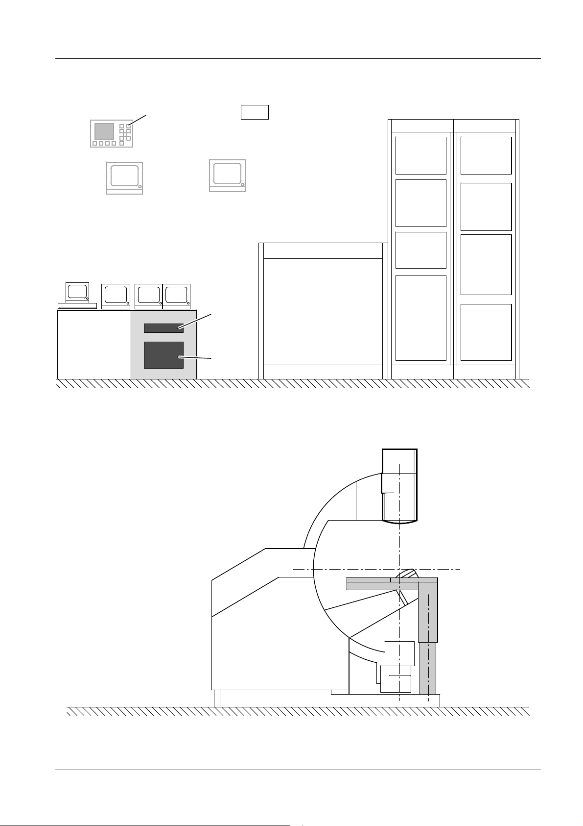
Component Overview 1
SC
3rd Monitor (Option)
PCMonitor
DICOM
Monitor
(Option)
Patient monitor
(Option)
Monitor I + II
Ultrasound unit
(Option)
Operating
system
unit
Multispot
or DICOM
Connect
(Options)
Diamentor
(Option)
Polydoros LX
AC
”HPE”
charger
N12
Shock
wave
controller
Cooling
unit
Water
prepara-
tion
A13
VIDEO-
MED
-DIM-
Image
storage
N11
System
controller
M16
Power
supply
A12
Siemens AG RXL2-120.812.01 Page 3 of 4 LITHOSTAR Multiline
Medical Solutions Rev. 02 10.04 CS PS 24 System
Page 8
1 - 4 General Remarks
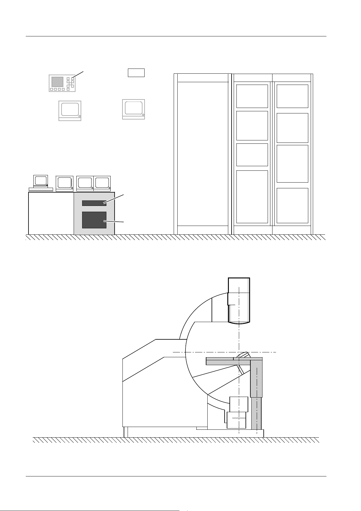
Component Overview 1
SC
3rd Monitor (Option)
PCMonitor
DICOM
Monitor
(Option)
Patient monitor
(Option)
Monitor I + II
Ultrasound unit
(Option)
Operating
system
unit
Multispot
or DICOM
Connect
(Options)
Diamentor
(Option)
Polydoros SX
AC
”HPE”
charger
N12
Shock
wave
controller
Cooling
unit
Water
prepara-
tion
A13
VIDEO-
MED
-DIM-
Image
storage
N11
System
controller
M16
Power
supply
A12
LITHOSTAR Multiline RXL2-120.812.01 Page 4 of 4 Siemens AG
System Rev. 02 10.04 CS PS 24 Medical Solutions
Page 9

System Installation 2
Preparation 2
Preinstallation work 2
2 - 1
p
p
p
p
• Check the condition of the table installation plate (floor plate).
• Check the cable feed-throughs for cabinets, system control console, and the unit for
usability.
Options: Monitor trolley and/or Patient monitor 2
• Check the cable feed-throughs for the Patient monitor for usability.
• Make sure that there is sufficient space for a Patient monitor.
Siemens AG RXL2-120.812.01 Page 1 of 14 LITHOSTAR Multiline
Medical Solutions Rev. 02 10.04 CS PS 24 System
Page 10
2 - 2 System Installation
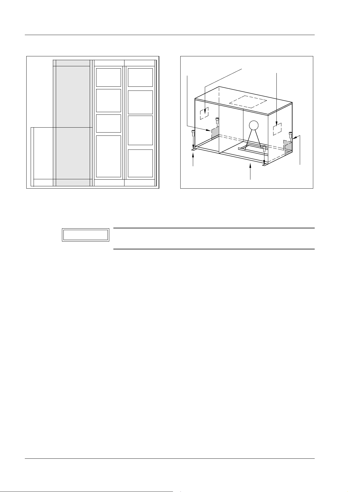
Cable lead-in
(on both sides)
Polydoros
SX 65
N12
N11
Polydoros
LX 30
M16
Mounting holes
AC
Fig. 1 Fig. 2
A13
A12
Cable lead-in from below
Generator and Cabinet Installation
Hand grip indentations
(on both sides)
2
Cable
lead-in from
the back
NOTICE
Do not insert the H1 high-voltage transformer until the generator
is cabled in the power cabinet.
With the exception of the cooling unit and the high voltage charger, the cabinets are
shipped from the factory completely assembled and are individually crated.
We recommend setting up and bolting down the generator according to the project plan or
Figure 1 before installing the remaining cabinets.
Polydoros LX 2
• Mark on the floor and drill the four mounting holes for the generator cabinet at its
intended location using the supplied template.
• Drill the holes and insert the Liebig anchors that are included in the shipment (Fig. 2).
• Remove all transport safety brackets from the generator.
• Take the generator off the pallet.
• If necessary, knock out the cable inlet in the generator cabinet for interconnections with
the adjacent cabinet. Install the edge protection strip (service package).
• Mount the generator in place b y inserting the 4 hex bolts into the Liebig screw anchors.
LITHOSTAR Multiline RXL2-120.812.01 Page 2 of 14 Siemens AG
System Rev. 02 10.04 CS PS 24 Medical Solutions
Page 11
System Installation 2 - 3
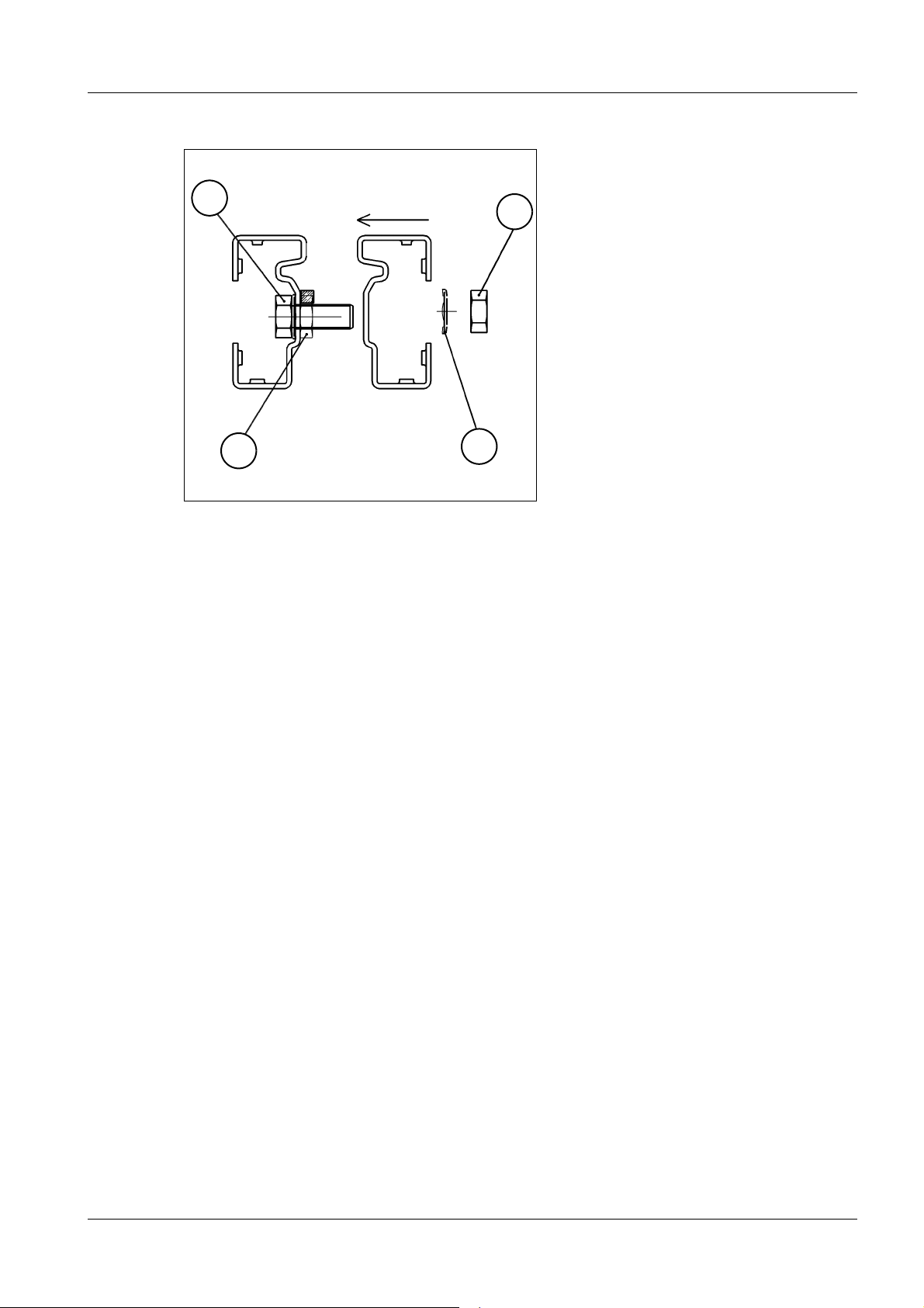
1
4
2
Fig. 3
3
Polydoros SX 65 2
• Move the power cabinet into its location.
• Attach the top of the cabinet to the wall with retaining brackets to prevent the cabinet
from tilting.
p
• If required, the cabinet can also be bolted to the floor.
• If required, remove the cover for the corresponding cable inlet on the generator cabinet.
• Mov e cabinets A12 and A13 to their location according to the project plan or the above
example (Fig. 1).
• The splash guard has to be installed between the control cabinet A 12 and the shoc k
wave cabinet A13. If necessary , turn it around.
• Install the side walls of the cabinets.
• Within the scope of validity of the UL regulations (e.g. USA) the metal case should not be
removed due to fire protection.
• Install the enclosed screw (1/Fig. 3) with nut (2/Fig. 3) to a cabinet to connect the cabinet.
Then move the second cabinet to its position and tighten with nut (4/Fig. 3) and flat
washer (3/Fig. 3).
• Move the cabinets to their final position and bolt them to the wall and the floor.
Installing and Connecting the High Voltage Charger 2
• Unpack the charging unit, place it on the rails provided in the shock wave cabinet above
the electronics unit N12 and secure it on the front using 4 screws.
• Connect the power line cable at N12 (1 on L1, 2 on N and ge/gn on PE).
• Plug in the cable from the N12, K108 to the charger controller on the charger.
Siemens AG RXL2-120.812.01 Page 3 of 14 LITHOSTAR Multiline
Medical Solutions Rev. 02 10.04 CS PS 24 System
Page 12
2 - 4 System Installation
a
ca. 1200
ca. 2300
b
ca. 1100
ca. 2400
2
Fig. 4 Fig. 5
c
ca. 1100
ca. 2620
Installing and Connecting the Cooling Unit 2
• Place the cooling system on the rails provided in the shock wave cabinet A13 (under the
N12 electronics unit), slide it into position and secure it on the front using two screws.
• Insert the hoses in the appropriate connections according to marking, and ensure that
they lock into position.
• Plug the power line connector for the cooling system into the socket on the electronics
unit at N12.X3.
• Connect the protective conductor between the cooling system and the shock wave
cabinet.
CAUTION
To avoid the risk of excessive heat build-up, make sure that the
ventilation inside and outside the cabinet is always sufficient.
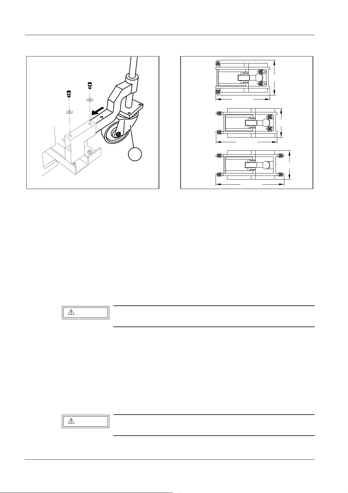
Setting Up the Unit 2
• Place the four transport rollers (2/Fig. 4) onto the transport carriage on the yellow
shipping frame at (c/Fig. 5) and bolt them in place.
• Remove the shipping pallet from the unit.
Lift the unit with the help of the spindles and pull the transportation pallets out to the side.
• Depending on the dimensions of the transport route, it may be necessary to reposition
the rollers on the carriage (Pos. a or b in Fig. 5) and bolt them in place.
For this reason, the unit should be lowered on an appropriate wooden base.
CAUTION
When lowering the unit, the cable harnesses must not be damaged.
• Move the unit to its installation location and place it next to the mounting plate.
LITHOSTAR Multiline RXL2-120.812.01 Page 4 of 14 Siemens AG
System Rev. 02 10.04 CS PS 24 Medical Solutions
Page 13

System Installation 2 - 5
Fig. 6 Fig. 7
• Put the insulation plates on top of the thoroughly cleaned mounting plate (Fig. 6)
(the drill holes for the equipment must not be covered).
• Uncoil the four cable harnesses that are permanently connected to the unit and lay them
out (Fig. 7).
• Guide the free ends of the cable harnesses into the opening in the mounting plate, and
into the corresponding cabinets via the cable conduits.
NOTICE
The cable harnesses are color-coded:
- blue for the shock wave cabinet
- green for the control cabinet
- yellow for the generator
The correspondingly color-coded target connections are located
in the cabinets.
Siemens AG RXL2-120.812.01 Page 5 of 14 LITHOSTAR Multiline
Medical Solutions Rev. 02 10.04 CS PS 24 System
Page 14
2 - 6 System Installation
8 x
4 x
Fig. 8 Fig. 9
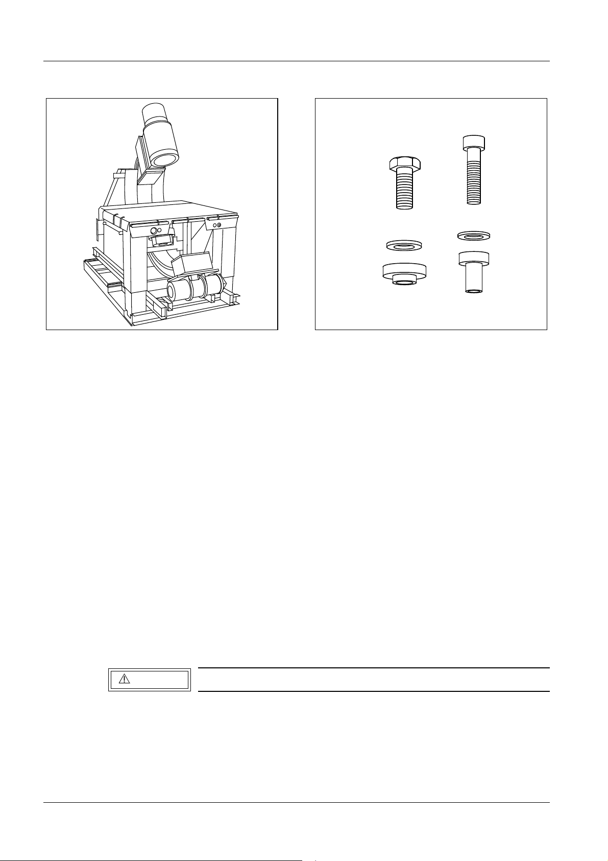
• Move the unit so that it is positioned correctly over the mounting plate and so that it is
level i.e., lower all four transport rollers evenly (Fig. 8).
• Mount the unit using 12 bolts and insulating sleeves on the floor. Apply Loctite 221 on the
bolt threads to secure them (Fig. 9):
- 8x Recessed socket head M 8 x 4 tighten to 24 Nm, ± 10%
- 4x Hex head M10 x 25
(The bolts are contained in the box with service materials.)
• Remove the entire transport device.
• Remove the yellow shipping brackets on the W-drive.
• Measure the resistance to ensure that the unit is electrically isolated on the mounting
plate.
• Carefully feed through the cable harnesses. Store any excess cable lengths. Roll them
up without kinks.
Do not place any excess cable or cable loops in the unit frame, since they may come into
contact with the moving energy chain and become damaged.
Do not block the movement of the energy chain.
CAUTION
Excess cable lengths may not be stored in the cabinets.
• Remove the transport safety bracket from the I.I. collision protection.
LITHOSTAR Multiline RXL2-120.812.01 Page 6 of 14 Siemens AG
System Rev. 02 10.04 CS PS 24 Medical Solutions
Page 15
System Installation 2 - 7
K
Fig. 10 Fig. 11
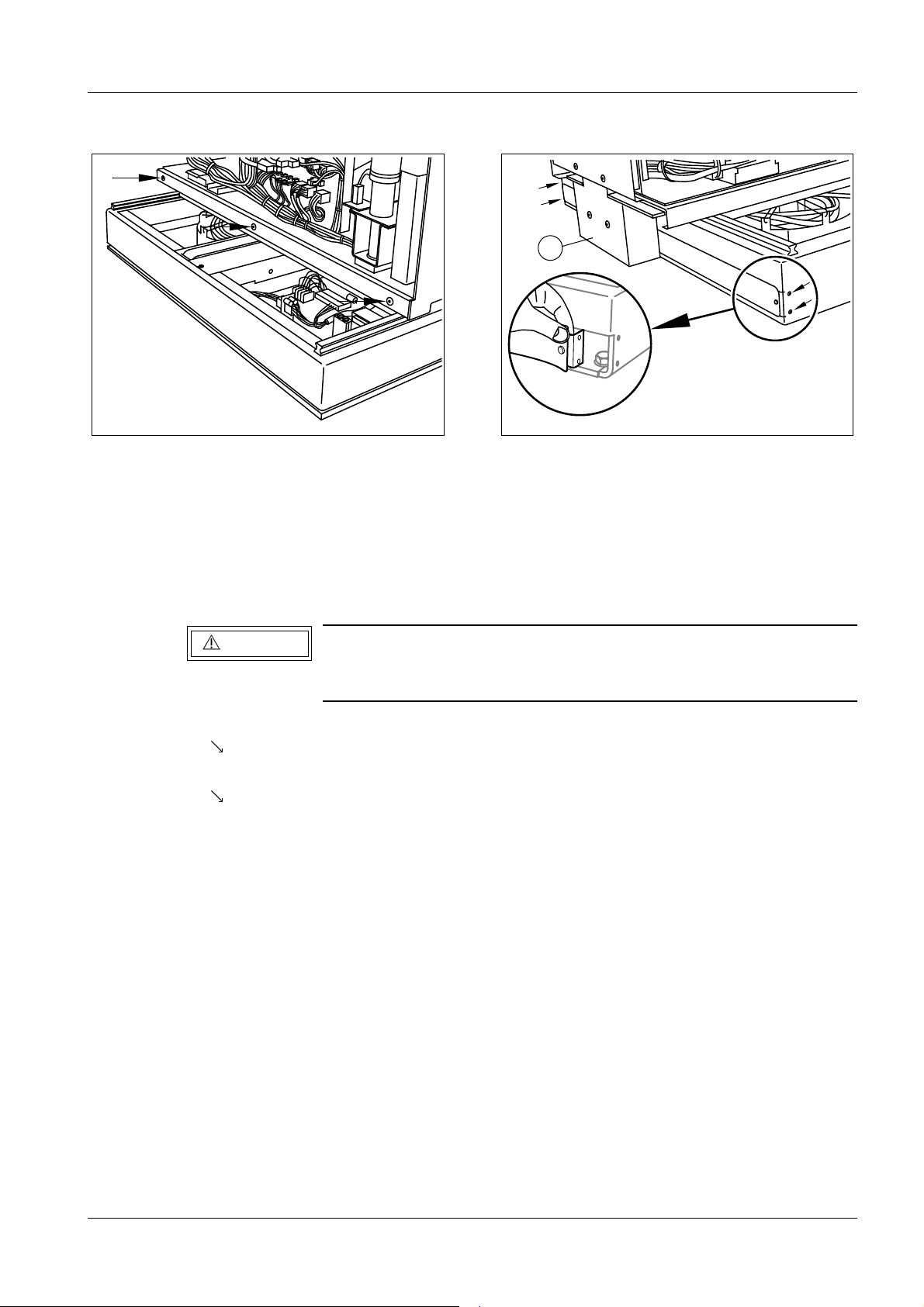
Installing the Covers 2
For all visible surfaces, special paneling screws with 2.5 Allen sockets have been provided.
• The required scre ws and washers are already counted out and packed in plastic bags.
CAUTION
Before installing the covers, connect eac h metal co ver to gr ound;
the connections are provided in the unit and on the cover panels
themselves.
• Secure the two lateral strips on the unit base frame with three paneling screws for each
( /Fig. 10).
• Install the rear metal roll-down sash in the unit base frame on the left and the right
( /Fig. 11); for this, the mounting brackets must be installed on the inside of the frame.
• Attach the cover (K/Fig. 11) for the cable routing using two paneling screws.
Siemens AG RXL2-120.812.01 Page 7 of 14 LITHOSTAR Multiline
Medical Solutions Rev. 02 10.04 CS PS 24 System
Page 16
2 - 8 System Installation
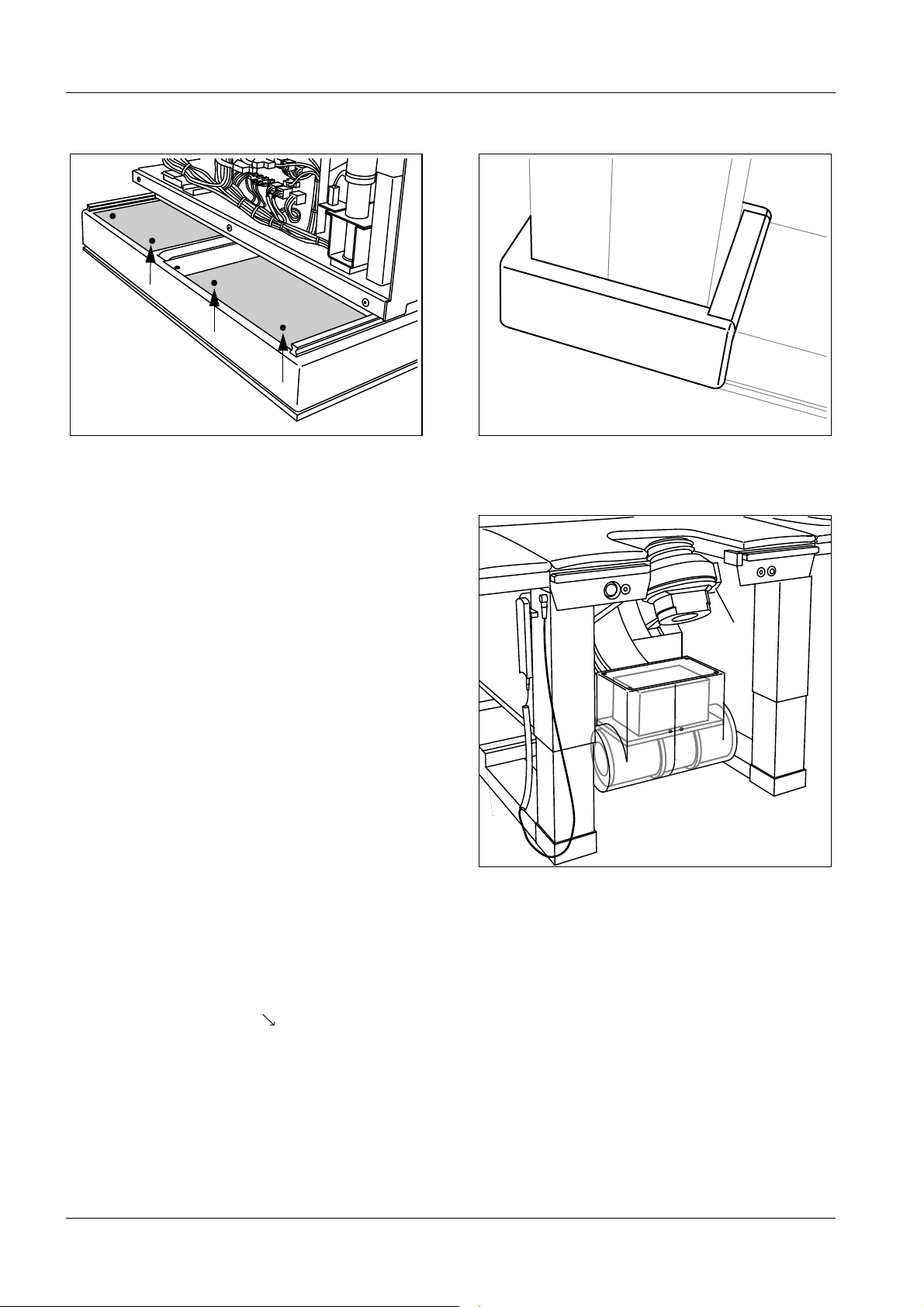
Fig. 12 Fig. 13
A
B
Fig. 14
• At this point you have to route the SONOLINE cables (see chapter 3, page 18 or
chapter 4, page 22) if the ultrasound option is being installed.
• Insert the two-part base frame cover and mount it in place using four paneling screws for
each part ( /Fig. 12).
• Install the kick plates on both table legs and fasten them together (Fig. 13).
• Attach the paneling to the underside of the shock head support (A/Fig.14).
• In the front section of the base frame (B/Fig. 14), use black plastic plugs to seal the two
holes for mounting the transport carriage.
LITHOSTAR Multiline RXL2-120.812.01 Page 8 of 14 Siemens AG
System Rev. 02 10.04 CS PS 24 Medical Solutions
Page 17
System Installation 2 - 9
PCMonitor
Fig. 15 Fig. 16
DICOM
Monitor
(Option)
Monitor I + II
Operating
system
unit
Multispot
or DICOM
Connect
(Options)
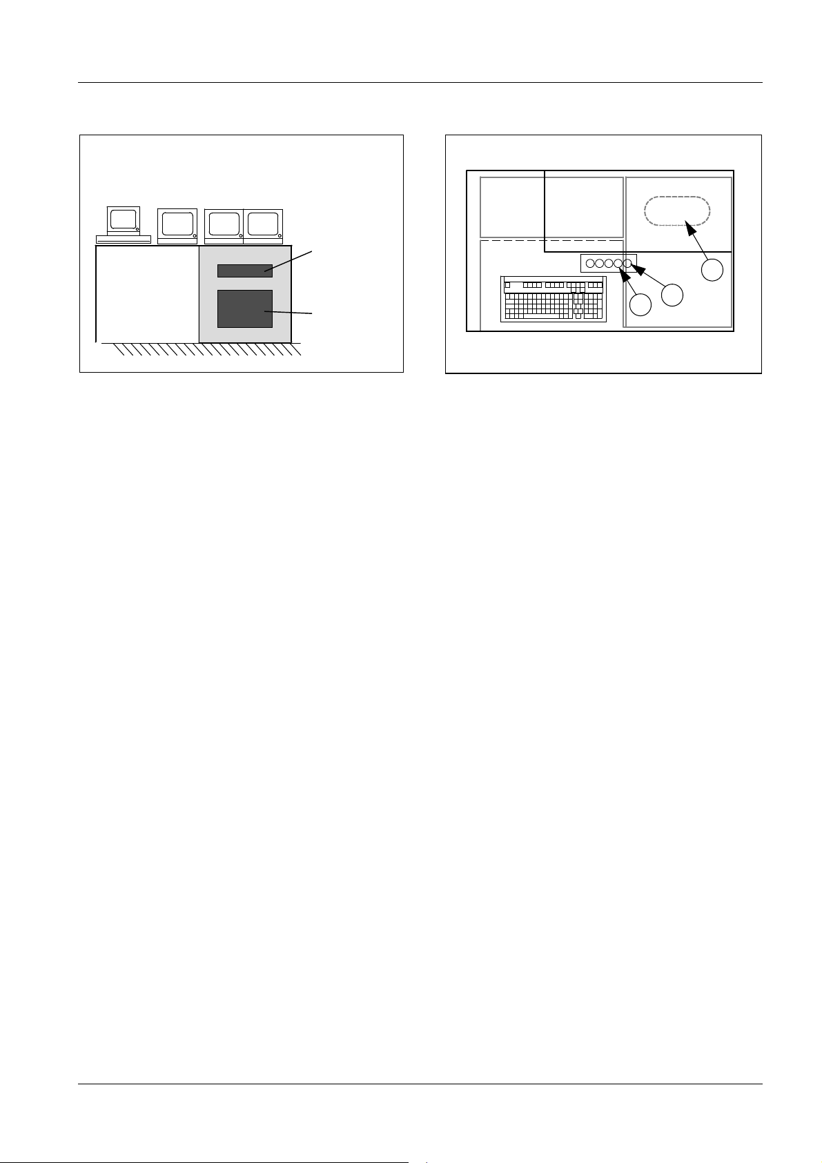
Installing the Components for the System Controller 2
Setting Up the Console Table 2
The cable outlet (A/Fig. 16) is set up at the factory for downward cable feed-through.
However, it is possible to route the cables to the back by punching out one of the perforated openings.
p
• Route the cable from the control console table to the control cabinet.
A
C
B
• If the Diamentor option is present, route the Diamentor cable from the electronics cabinet
to the console table.
Positioning/Connecting the Monitors 2
• Place the monitors on the control console table as shown in Fig. 15 and connect them
per their designations.
Positioning the Keyboard and the PC Mouse 2
• Place the keyboard and the PC mouse on the control console table.
• Connect the cable to the keyboard.
Connecting the Footswitch, Tableside Control Console, Shock Wave Trigger Mechanism 2
• Connect the tableside control without the holder (optional) (B/Fig. 16) and the (C/Fig. 16)
shock wave release control to the console table.
• Connect the footswitch for fluoroscopy (optional) either to the console table or to the unit:
- Right back panel of the unit,
- Under the foot support at the control console table.
• Connect the tableside control with the holder to the unit.
• Connect the unit footswitch (optional) on the right in back of the unit.
Siemens AG RXL2-120.812.01 Page 9 of 14 LITHOSTAR Multiline
Medical Solutions Rev. 02 10.04 CS PS 24 System
Page 18
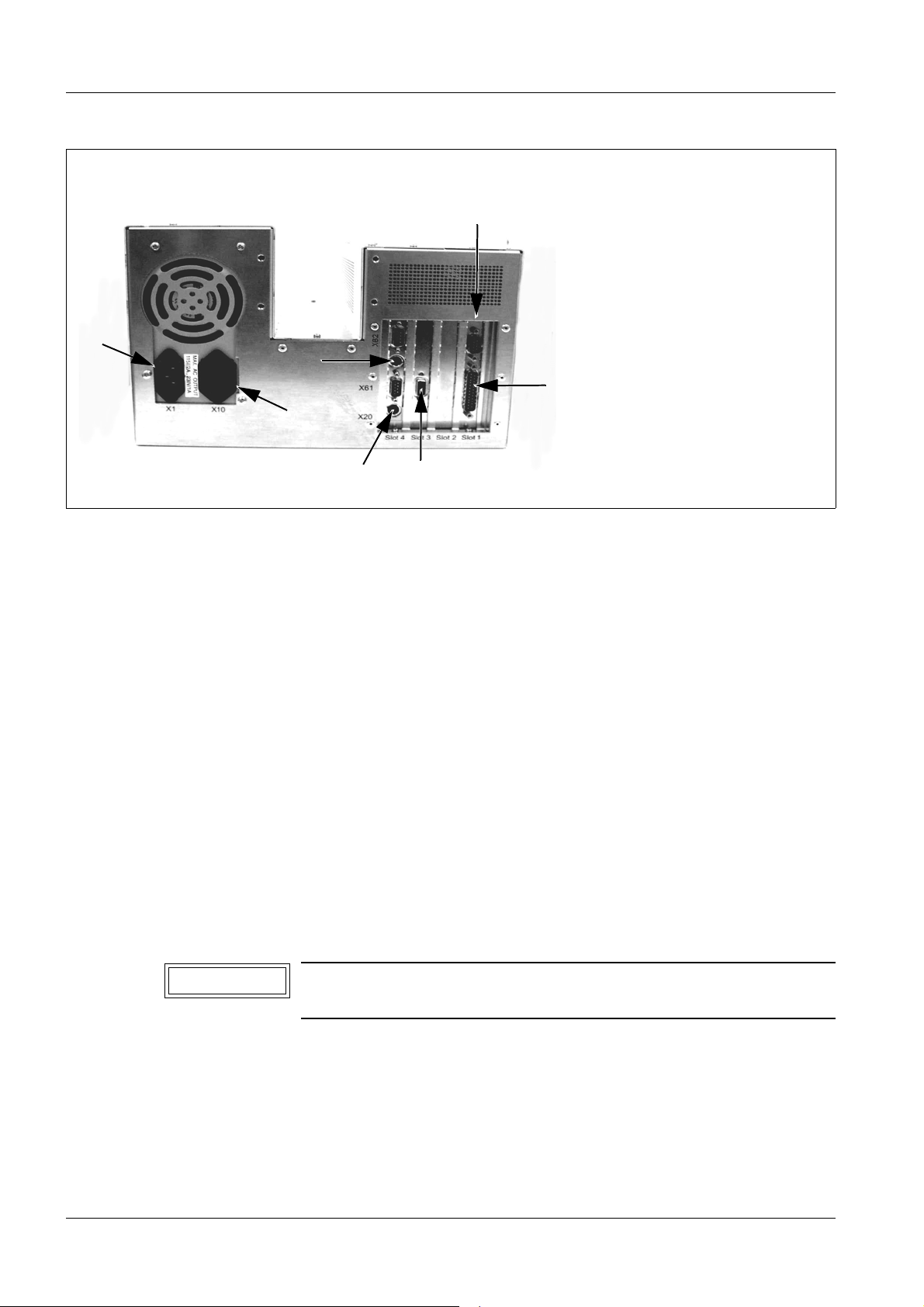
2 - 10 System Installation
1 Keyboard port
X51
7
2
4
2 Mouse port
4 Monitor power line connector
6 Monitor port
7 Power line connector
X50 Respirator-ECG signal interface
X51 DUEP port
X50
LM - Control Unit
Fig. 17
Back panel of the PC 2
Positioning/Connecting the Operating System Unit (PC) 2
• Open the door on the console table and pull out the PC slide-out shelf.
• Position the operating system unit on PC slide-out shelf and secure it from below.
• Connect the cables for the mouse, the keyboard, the monitors and the DUEP cable at the
• Connect the power line cable to the operating system unit.
• Insert the slide-out shelf. Pay attention to the cable routing in the console.
Cover the cable outlet 2
• In areas where UL regulations apply,(e.g. USA) you must cover the cable outlet with the
Positioning/Connecting DICOM Connect (Option) 2
1
PC (Fig. 17).
extra aluminum sheet located in the operating console as fire protection.
6
• Perform installation and startup according to the manual RXL2-120.814.02..
NOTICE
LITHOSTAR Multiline RXL2-120.812.01 Page 10 of 14 Siemens AG
System Rev. 02 10.04 CS PS 24 Medical Solutions
DICOM can be built into the LITHOSTAR Multiline only if no
MULTISPOT is installed.
Page 19

System Installation 2 - 11
Positioning/Connecting the Multiformat Camera (Option) 2
• Connect the Multispot per the designations and place it on the console table as shown in
Fig.15 and tighten the screws. The cables can be found in the console table (power,
video, control cable).
NOTICE
The two Allen screws in the base of the Multispot have to extend
into the drilled holes of the intermediate plate in the operating
cabinet. Depending on the customer's request, the drilled holes
on the front or on the back can be used.
Positioning/Connecting the Diamentors (Option) 2
• Plug the power cable into the multiple socket outlet of the console desk (slide-out-shelf).
• Lead the cable up through the free opening.
• Connect the cable routed from the measuring chamber of the Diamentor via the adapter
cable supplied.
• Connect the cable routed from power supply unit at the Diamentor.
• Position the Diamentor on the console desk.
Siemens AG RXL2-120.812.01 Page 11 of 14 LITHOSTAR Multiline
Medical Solutions Rev. 02 10.04 CS PS 24 System
Page 20
2 - 12 System Installation
2
1
Fig. 18
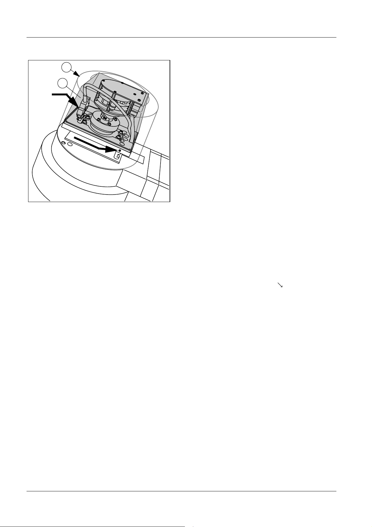
Installing the TV camera on the 23" I.I. 2
• Remove the housing (1/Fig. 18) from the TV camera.
• Remove the cover of the I.I. optics (black lid).
• Remove the set screws on the longer sides of the TV camera.
• Place the TV camera on the I.I. and mount it with the two set screws ( /Fig. 18).
• Plug in the two connection cables on the TV camera and secure them (Fig. 18).
• Clamp the shielding of the camera cable D115.X2 under the clamp.
• Reinstall the TV camera housing (1/Fig. 18) but do not secure it.
• Connect the protective conductor to the white cover (2/Fig. 18).
• Place the white cover (2/Fig. 18) over the TV camera and secure it together with the
housing.
• Use the white plastic plugs to cover the holes.
Installing the TV camera on the 33" I.I. 2
• The camera has been pre-installed at the factory.
Checking the temperature of the image intensifier 2
• Check the temperature indicators of the image intensifier according to the installation
instructions regarding temperature checks with SIRECON units and OPTILIX tubes in
RXD0-000.038.01... The results of the evaluation are recorded in the image quality
protocol (IQC) during start-up.
LITHOSTAR Multiline RXL2-120.812.01 Page 12 of 14 Siemens AG
System Rev. 02 10.04 CS PS 24 Medical Solutions
Page 21
System Installation 2 - 13
1
1
2
Fig. 19 Fig. 20
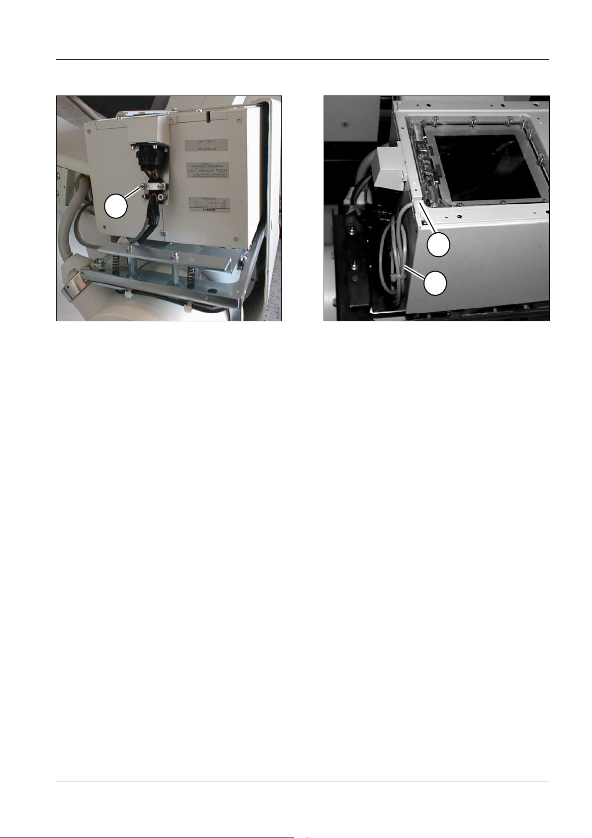
Installing the Collimator 2
• Unpack the collimator.
• Remove the screws from the transport brackets at the side of the blades close to the
focus.
• Check the adjustment of the blades close to the focus with the template.
• Attach the collimator to the tube unit.
• Plug in connector X1 on the collimator.
• Secure the wire to the panel using strain relief clamps (1/Fig. 19).
• Connect the plug.
Installing the Diamentor (Option) 2
• Remove the cover from the collimator.
• Insert the measuring chamber and lead the cable out through the opening (1/Fig. 20).
• Reattach the cover to the collimator.
• Plug the two connectors together and fix the cable with the cable ties (2/Fig. 20).
Siemens AG RXL2-120.812.01 Page 13 of 14 LITHOSTAR Multiline
Medical Solutions Rev. 02 10.04 CS PS 24 System
Page 22

2 - 14 System Installation
Installing the Simomed N44 monitor (OPTIONAL)
NOTICE
Refer also to installation instructions RX53-020.031.06..
• Remove the monitor housing.
• Slide the monitor onto the holder of the monitor trolley. The monitor should lock into
position.
• Tighten the two rear screws.
• Connect the cables according to the labels.
• Clamp the shielding of the BAS lead under the clamp of the VIDEO
cable.
IN
• Establish the protective conductor connections.
• Reinstall the monitor housing.
System with Polydoros LX chapter 3
System with Polydoros SX chapter 4
LITHOSTAR Multiline RXL2-120.812.01 Page 14 of 14 Siemens AG
System Rev. 02 10.04 CS PS 24 Medical Solutions
Page 23

Connections with POLYDOROS LX 30 3
3 - 1
Cables in zipper hose
Cables fixed to the object
Control console
green
Fig. 1
General information 3
The cable harnesses are enclosed in zipper hoses and are color coded.
The specific target connection points for the harnesses have the same color coding in the
cabinets:
X-ray
generator
Shock wave
cabinet
AC
A13
A12
Patient
monitor
Option
Electronics
cabinet
Green
3rd Monitor
Option
Unit
Ultra-
sound unit
Option
Blue
yellow
X-ray generator, AC: yellow
Shock wave cabinet, A13: blue
Electronics cabinet, A12: green
- The conductor and cable shields have to be connected at the ends with the
corresponding clip.
CAUTION
Do not open the connector housing on the cable between the
camera and the VIDEOMED DI-M (D8.X1) under any circumstances.
• Do not shorten the harness.
• Whenever possible, avoid overlapping or looping harnesses in the system and
particularly in the cabinets. Do not store excess cable lengths in the cabinets
(EMC reasons).
• Be careful that the cable harnesses do not get caught in the swing-out frames.
• Water hoses 5 and 8 may only be shortened by max. 5 m.
CAUTION
Do not step on the hoses. Avoid small loops and kinks as this
may damage them.
Siemens AG RXL2-120.812.01 Page 1 of 20 LITHOSTAR Multiline
Medical Solutions Rev. 02 10.04 CS PS 24 System
Page 24

3 - 2 Connections with POLYDOROS LX 30
Connections and cable locations in the A12
electronics cabinet
(green cable harnesses)
• Fasten the 3 cable harnesses (green) with the cable clip on the rail that
VIDEOMED
-DIM-
8
7
is installed at the bottom of the electronics cabinet.
right - cable harness,green, from control console
centre - cable harness,green, from unit (K3, K4....)
left - cable harness, green, from unit (K8, K9....)
• Secure the braided shield of the zipper hoses to the locations provided.
3
Image Storage
N11
System
Controller
9
M16
Power Supply
5
10
• Route the cables in the A12 electronics cabinet as shown in the adjacent
Fig. 2 and connect them according to table 1 and 3.
The numbers or letters (e.g. ) are located in the cable lists on the
4
following pages.
• Prior to routing the system cables, remove the EMC shielding plate at
N11 D11.
6
4
D21
4
X15
X4
X14
A12
L1
L1.1
L1.2
L2
X3
Cable harness, green, from the control console
Cable harness, green, from unit (K3, K4....)
Cable harness, green, from unit (K8, K9....)
3rd monitor on monitor trolley (optional)
Video cable 3rd monitor
Mounting rail for cable harness
Fig. 2
LITHOSTAR Multiline RXL2-120.812.01 Page 2 of 20 Siemens AG
System Rev. 02 10.04 CS PS 24 Medical Solutions
Page 25

Connections with POLYDOROS LX 30 3 - 3
X6
A.. D
A
X41
E
X200
D110
D115
D100
K32/K31
D200
C
SNT
X3
D220
X4
H1
X5
X9
D160
F1
F2
F3
K20
K30
Fig. 3
B
D
M16
D165
Connections/cable locations in the generator cabinet (Part A) 3
• Route the cable harnesses in the generator cabinet as shown in Fig. 3 above,
and connect them as indicated in Tables 1 and 2:
Multiline power line connections
• Connect the power harness for the Multiline in the M16 at terminal strip K30 ( /Fig. 3)
(see also the POLYDOROS LX Wiring Diagram, X2169-11):
- K30.L1, L2, L3 (is switched over the GS breaker with generator ON).
- K30. N and K30. terminal pins ( /Fig. 3).
• Strain-relieve the power harness (shielding under the clamp).
B
B
D
Siemens AG RXL2-120.812.01 Page 3 of 20 LITHOSTAR Multiline
Medical Solutions Rev. 02 10.04 CS PS 24 System
Page 26

3 - 4 Connections with POLYDOROS LX 30
AC Generator - A12 Electronics Cabinet - A13 Shock Wave Cabinet Connections
Type cable/
connection
2
4 x 4 mm
+
Gnd, shielded
1 x 6 mm
2
Function
MULTILINE
power supply
Protective con-
Generator
AC
M16.k30,
L1, L2, L3, N
M16.k30, M16,
A12 Cabinet A13 Cabinet ok
B 5
M16.X1 , N
F7, F8, F9
D 5
ductor
9 pole Canon XCS D200.X3 VDIM.D5.X13
9 pole Canon Act. value
D100.X200 N11.D6.X8
C 7
E 6
interface
3 x 1.5 mm
shielded
1 x 6 mm
2
2
,
A13 Power
supply
Protective con-
M16.X2.
L3, N, PE
M16, base
5 2
N12.X1.
L, N, PE
5 2
ductor
Canon Controller N11.D11.k104 N12.k104
Tab. 1
1)
Connections and cable position in cabinet A13 see fig. page 3-11
4 2
1)
1)
1)
System Operating Console - Generator Connections
This cable is located in the “System control console-Electronics Cabinet” zipper hose
Type of cable/
connector
Function
In Control
Console
in AC Generator ok
15 pole, Canon System ON/OFF Door D160.X9
Tab. 2
Connecting the XCS harnesses and
C E
• Pull the XCS harnesses (coming from the electronics cabinet) on the left side into the
power cabinet, guide them up and connect them on boards D100.X200 and D200.X3
C
per their designations (Fig. 3).
• Strain- relieve the harnesses using cable ties.
Control console connections
• Plug in the control console harness on board D160.X9 as shown in Table 2
A
( /Fig. 3).
• Strain- relieve the harness on the side using cable ties.
A
E
LITHOSTAR Multiline RXL2-120.812.01 Page 4 of 20 Siemens AG
System Rev. 02 10.04 CS PS 24 Medical Solutions
Page 27

Connections with POLYDOROS LX 30 3 - 5
Power and voltage supply connection, protective conductor connection in A12
Type of cable/connection Function
1 x 16 mm
2
Protective conductor Device PE M16.PE
Cable harness in the middle
3 x 1.5 mm
harness in the middle
4 x 2.5 mm
harness in the middle
3 x 1.5 mm
on the right
1 x 6 mm
2
, shielded cable
2
, shielded cable
2
, shielded cable
2
Power connection
Z96
Voltage supply of
the output stages
Power connection
control console
Protective conductor PE control console M16.PE
Right cable harness
Tab. 3
Device /
control console
Cabinet A12 ok
Device X11.1, 2, 3 M16.X2
L1, N, PE
Device K1 M16/D21.
X14, L1.2
Socket control console
M16.X2
L2, N, PE
5
5
4
5
5
Siemens AG RXL2-120.812.01 Page 5 of 20 LITHOSTAR Multiline
Medical Solutions Rev. 02 10.04 CS PS 24 System
Page 28

3 - 6 Connections with POLYDOROS LX 30
Connections of the options and their
cable locations in the A12
VIDEOMED
-DIM-
8
7
Image Storage
10
6
N11
System
Controller
9
4
electronics cabinet and generator AC
• Attach the special cables for the 3rd monitor to the
rail at the bottom of the electronics cabinet A12.
Install the cables as shown in Fig. 4 and connect
them according to table 4.
Patient monitor connection
• Position the patient monitor in the location provided
per the project planning guide (e.g. ceiling support).
• Plug the cable into the "SYNC" connector of the
patient monitor.
• Connect the patient monitor to its own power supply,
i.e. one that is independent of the LITHOSTAR
Multiline.
CAUTION
Do not establish any protective
conductor connections to the
LITHOSTAR.
9
3
M16
Power Supply
5
A12
Rail for cable harness
Fig. 4
Cable harness, green, from the operating console
Cable harness, green, from the unit (K3, K4....)
Cable harness, green, from the unit (K8, K9....)
3rd monitor on the monitor trolley (option)
Video cable 3rd monitor
LITHOSTAR Multiline RXL2-120.812.01 Page 6 of 20 Siemens AG
System Rev. 02 10.04 CS PS 24 Medical Solutions
Page 29

Connections with POLYDOROS LX 30 3 - 7
Connections for the Options in the A12 Electronics Cabinet or in the AC Generator
Type of cable /
connector
3 x 1.5 mm
1 x 4 mm
2
2
Function Optional Unit
Line voltage 3rd Monitor * A12/M16.X2.L2, N, PE
Protective conduc-
Monitor trolley A12/M16
A 5
In the A12 Cabinet or
in the AC Generator
tor
Coax cable Video Monitor trolley A12/Monitor 3
Radiation ON display
Monitor trolley AC/D160.X6 see
generator wiring
in
diagram X2169-11
K14 ECG control Patient monitor "SYNC" A12/N11/D11.k14
Tab. 4
A
* The monitor cable contains more cable than necessary for connecting the
LITHOSTAR Multiline. Roll up the additional cables and place them in the control
cabinet.
ok
5
9
Siemens AG RXL2-120.812.01 Page 7 of 20 LITHOSTAR Multiline
Medical Solutions Rev. 02 10.04 CS PS 24 System
Page 30

3 - 8 Connections with POLYDOROS LX 30
Connections and cable locations in the
A12 electronics cabinet
VIDEOMED
-DIM-
8
7
Image Storage
10
6
N11
System
Controller
9
4
and in the control console
(cable harness, green)
• Route the cables in the A12 electronics cabinet,
as shown in Fig. 5 and connect them as shown in
Table 5, 6 and 7.
VIDEOMED connection:
• Remove the XCS cables X11 and X12 from the D5
board.
• Remove the EMC shielding on the Videomed.
• Route the camera connector D8.X1similar to the video
cable underneath the rack and connect it to the
backplane as shown in Table 5.
Remove board D1 for this purpose.
• Attach the cable with a cable clip to the rack above the
shield.
• Attach the EMC shielding on the Videomed.
• Connect the XCS cables X11 and X12 on the D5 board.
8
3
M16
Power Supply
4
5
A12
Cable harness, green, from the control console
Cable harness, green, from the unit (K3, K4....)
Cable harness, green, from the unit (K8, K9....)
3rd monitor on the monitor trolley (option)
Video cable 3rd monitor
Mounting rail for cable harness
Fig. 5
LITHOSTAR Multiline RXL2-120.812.01 Page 8 of 20 Siemens AG
System Rev. 02 10.04 CS PS 24 Medical Solutions
Page 31

Connections with POLYDOROS LX 30 3 - 9
Unit - A12 Electronics Cabinet Connections (left Cable Harness, green)
Type of cable /
connector
Function In Unit In Cabinet ok
12 pole connector, k8 Motor controller I D32.X54 N11/D11.K8
12 pole connector, k9 Motor controller II D32.X55 N11/D11.K9 3)
Special connector Control and
power supply
for the collimator
Special Camera Camera,
Collimator,
Z66.X1
D115.X2
N11/D6.X3
M16/D21.X4
VIDEOMED DI-M
D8.X1 on back-
4)
plane
Special Dose measurement
chamber
(optional Diamentor)
Tab. 5
Measurement
chamber collimator
Diamentor
(Control console)
3) Remove EMC shielding on the D6 board
Insert cable
Reattach the EMC shielding and make sure that the cable is in the
recess of the EMC cover.
4) After connecting D8.X1, install the EMI shielding plate.
(refer also to VIDEOMED connection in Chapter 3 page 8).
9
9
6
4
8
Unit - A12 Electronics Cabinet Connections (center Cable Harness, green)
Type of cable /
connector
4 pole connector k7 Power supply for the
Function In Unit In Cabinet ok
D31.X34 M16/D21.X3
magnetic brakes
37 pole connector k3 Incremental sensor D31.X30 N11/D11.K3
37 pole connector k4 Actual values D31.X31 N11/D11.K4
37 pole connector k5 Switches and DÜP D31.X32 N11/D11.K5
50 pole connector k6 Motor and magnetic
D31.X33 N11/D11.K6
brake control
9 pole connector k12 Zoom selection N11/D11.K12
9 pole connector k13 Respirator sensor
D27.X1 N11/D11.K13
connection
Tab. 6
4
4
4
4
4
4
9
Siemens AG RXL2-120.812.01 Page 9 of 20 LITHOSTAR Multiline
Medical Solutions Rev. 02 10.04 CS PS 24 System
Page 32

3 - 10 Connections with POLYDOROS LX 30
System Control Console - Electronics Cabinet Connections (right Cable Harness, green)
Type of cable /
connection
Function In Control Console In A12 Cabinet ok
25 pole, Canon Controller Slide-out shelf N11/D11.K11
9 pole, Canon 4 channel
ECG - monitor
Coax video cable Video input
Monitor 1
in
Coax video cable Video input
Monitor 2
in
Coax video cable Video connection
Monitor 1
⇒ Monitor 3
Coax video cable Hardcopy input MULTISPOT
9 pole, Canon Hardcopy control MULTISPOT
Tab. 7
4 channel
ECG - monitor
1.Video monitor
Monitor 1
in
2.Video monitor
Monitor 2
in
3.Video monitor
Monitor 1
Monitor 3
out
in
N11/D11.K103A
MEMOSKOP,X11
MEMOSKOP,X12
9)
o to 3rd
7)
monitor if
configured
9)
MEMOSKOP, X10
9)
MEMOSKOP, X4
• connect to the monitor , only if a third monitor is present. 7)
8)
8)
10)
8)
8)
4
9
10
10
10
10
10
• Options 9)
• The coaxial cab le should be attached with a cable clip to the rail in the electronics
cabinet A12. Electrically Isolate the coaxial plug from the rack of the cabinet.
10)
• Check the switch positions on the back of the monitors and ensure that the setting is as
follows:
- Video signal to 0.3 V.
- If no third monitor is present, terminate both monitors at 75 Ohms.
- If a third monitor is present, set the output of the first monitor to high.
• Reattach the EMC shielding plate on the N11 D11. Make sure that all the cables are in
the recesses and will not get damaged when reattaching the shielding plate.
• After connecting the MEMOSKOP cabling, reinst all the MEMOSKOP cover.
The cable shielding must be under the corresponding clamp.
8)
LITHOSTAR Multiline RXL2-120.812.01 Page 10 of 20 Siemens AG
System Rev. 02 10.04 CS PS 24 Medical Solutions
Page 33

Connections with POLYDOROS LX 30 3 - 11
Connections/cable locations in the A13
shock wave cabinet
3
HPE″
Charger
1
N12
Shock Wave
Controller
2
Cooling Unit
(cable harness, blue)
• Attach the blue cable harness in the shock wave
cabinet A13 on the front and back cabinet rack at pos.
6 and 7 with cable clips. Refer to Fig. 6. Attach the
braided shield of the zipper hose to the plate provided
at pos. 8 /9.
• Route the cables for the A13 shock wave cabinet as
shown in the Fig. left and connect them as shown in
Table 8.
• Secure the cables leading to N12 with cable ties on
the right side of position 50/52.
Make sure the conductors to D19 and D91 have
sufficiently long.
• For connecting the cables to the charger you have to
tilt M12 toward the front. Use cable ties to secure the
cables on the right side of position 67/68.
• Connect the hoses for the water connections at the
input/output point in the shock wave cabinet per
their designations or as shown in connection Table 8
and secure them with hose clamps.
3
Fig. 6
Water
Preparation
3
A13
• Make sure there are no kinks in the hoses and that
they are secured.
Connection point
for blue cable har-
NOTICE
The hoses must not be shortened
by more than 5 m, if required
Siemens AG RXL2-120.812.01 Page 11 of 20 LITHOSTAR Multiline
Medical Solutions Rev. 02 10.04 CS PS 24 System
Page 34

3 - 12 Connections with POLYDOROS LX 30
o
Connection, Unit - A13 Shock Wave Control Cabinet (blue cable harness)
Type of cable /
connector
Function In Unit In Cabinet ok
Special Trigger lead X2, Power unit N12.X2
“ Test lead U/2 X5, Power unit N12.D91.X2
“ Test lead U
“ Test lead I
meß
meß
X4, Power unit N12.D91.X2
X3, Power unit N12.D91.X3
EK20 special Fan power supply X40, Power unit N12.K4
EK20 special Coupling X12, coupling assembly N12.K5
9 pole, Canon Coding X13, Power unit N12.K103
9 pole, Canon Shock head sensors X11, Shock wave head N12.K101
9 pole, Canon Coding Shock wave head N12.K102
Special K26 charger lead X1, Power unit Charger
1 x 4 mm
2
Protective conductor Power unit PE, Charger
Type of hose
Water Cooling system intake Shock wave head 5 Exchanger
2
5)
2
5)
2
5)
2
2
2
2
2
2
6)
1
6)
1
3
Water Cooling system return Shock wave head 8 Exchanger
Tab. 8
5) Allow enough cable length so that the boards can be unplugged with the
cables still connected.
6) - T o connect these cab les, swing the N12 out tow ards the front.
- Check that the screw connections of the high
voltage connector K26 are tightened securely
(refer to Fig. 7 on the left).
- Insert the connector of high voltage cable K26 on
the bottom of the charger until it locks audibly int
position.
- The connection (jumper) between and 0V
must be present.
Fig. 7
3
LITHOSTAR Multiline RXL2-120.812.01 Page 12 of 20 Siemens AG
System Rev. 02 10.04 CS PS 24 Medical Solutions
Page 35

Connections with POLYDOROS LX 30 3 - 13
X41
A... D
D100
X200
D115
K32/K31
F
G
H
D200
X3
D110
K30
D220
M16
D165
Z
SNT
X9
D160
X6
X
X4
X5
H1
K20
F2
F1
F3
L
I
Fig. 8
Connections/Cable Locations in the Generator Cabinet (Part. B) 3
• Route the cables in the generator cabinet as shown in Fig. 8 above, and connect them in
accordance with Table 9:
• Install the yellow cable harness in the generator cabinet below M16. Connect the
shielding of the zipper hose to the bolt in M16 ( /Fig. 8). To strain-relieve the zipper
hose, attach it with a cable tie to the left intermediate plate of the cabinet near the floor
L
( /Fig. 8).
Rotating anode cable connection
• Route the rotating anode cable (internally required length approx. 1 m) up along the right
side in the frame of the generator cabinet to the anode starter ( /Fig. 8).
• Connect the braided shielding (external shielding) of the end of the lead to the right side
of the starter unit under one of the clamps ( /Fig. or 1/Fig. 9).
F
• Connect the red cable (inner shielding) to (3/Fig. 9).
• Strain-relieve the cable using cable ties (2/Fig. 9).
• Connect the rotating anode cable to the breaker of the anode starter ( /Fig. 8):
I
F
F
On breaker, contact: K31/R2 K31/R4 K32/R2
Anode cable leads: I / 1 0 II / 2
Siemens AG RXL2-120.812.01 Page 13 of 20 LITHOSTAR Multiline
Medical Solutions Rev. 02 10.04 CS PS 24 System
Page 36

3 - 14 Connections with POLYDOROS LX 30
K32
K31
Fig. 9 Fig. 10
Generator - Unit Connections (Cable Harness, yellow)
Type of Cable Function Generator System ok
Stator cable
3 x 0.75 mm
2
Rotating anode drive Anode starter
K31.R2, R4, K32.R2
2 x HSK HV power supply HV-Transf. H1.API X-ray tube
1 x 6 mm
2
3 x 0.25 mm
2
Protective conductor - bolts
(on M16 under K20)
Oil pressure switch D160.x6.1 u. x6.3
shielding at
X
F
X-ray tube I, 0, II
H
I
X-ray tube
X
X-ray tube
Iontomat No function on the
Polydoros LX
Tab. 9
Connecting the H1 High Voltage Transformer
• Remove the inverter cover and open the bayonet connectors (1/Fig. 10).
• Change the position of the transformer mount (Fig. 10) and swing it out.
• Place the high voltage transformer on the transformer mount.
• Route the high voltage harnesses up to the high voltage transformer (3/Fig. 11).
• Check the oil level in the high voltage receptacles (approximately 1 cm); if necessary,
refill with oil (part no. 44 10 023 RV090 1 liter).
• Insert the high voltage plug without silicone disk but with silicone gasket into the correct
receptacle of H1 (Workstation 1).
LITHOSTAR Multiline RXL2-120.812.01 Page 14 of 20 Siemens AG
System Rev. 02 10.04 CS PS 24 Medical Solutions
Page 37

Connections with POLYDOROS LX 30 3 - 15
t
-
• Slide the H1 high voltage transformer into the generator cabinet.
• Change the position of the transformer mount (Fig. 10), lift it, and lock in the bayonet
connectors (1/Fig. 10) of the mount.
• Connect the high voltage cable shielding to (Z/Fig. 8) (if the shielding is not accessible in
the clamping area, remove the outer insulation).
The clamps are located in the generator service packet.
• Use cable ties to strain-relieve the cab les
(3/Fig. 11).
• Carefully remove the plastic guard plate for board
D220 with symbols (1/Fig. 11).
• Connect the protective conductor strap to the
H1. (2/Fig. 11).
• Attach the (primary) leads H1.U1 and H1.V1 of the
inverter module per the designation onto H1
(3/Fig. 12).
Fig. 11
• Route the cable connected to D220.X41
(4/Fig. 11/12) down to the D160 board and connec
it to X44.
• Clamp the braided shield of the cable under the
clamp (5/Fig. 11).
• Use cable ties to strain-relieve the cab le at H1
(6/Fig. 12).
• Plug the flat cable X1 from board D100 to
connector X1 on board D220 (7/Fig. 12) and strain
relieve it on the co ver (shielding underneath the
strain relief).
• Reinstall the guard with the symbols
(1/Fig. 11).
• Check the nuts on the protective conductor studs
(8/Fig. 12) and tighten them, if necessary .
Fig. 12
Siemens AG RXL2-120.812.01 Page 15 of 20 LITHOSTAR Multiline
Medical Solutions Rev. 02 10.04 CS PS 24 System
Page 38

3 - 16 Connections with POLYDOROS LX 30
D110
D110
F1
F1
F2
F2
F3
F3
K20
K20
H1
H1
K30
K30
D220
D220
D115
D115
K3
K32/K31
D165
D165
X6
X6
A... D
A... D
X9
X9
K
K
X41
X41
D100
D100
SNT
SNT
D160
D160
X200
X200
D200
D200
X3
X3
X4
X4
X5
X5
Fig. 13
J
J
M16
M16
Connections/harness locations in the generator cabinet (Part C) 3
• Route the harnesses in the generator cabinet as shown in Fig. 13 above, and connect
them in accordance with Table 10:
Generator power line connection
Nominal Line Voltage: 400 V ± 10%.
• Secure the screw type terminals from the service packet to the conductors of the power
cable. If the power cable diameter is small enough, turn the clamps 180° (both curvatures opposite to each other).
• Insulate the harness terminals that have been installed using heatshrink tubing.
• Remove the cover over the knife breakers F1, F2 and F3 ( /Fig. 13) at the M16 of the
generator.
• Connect the power line leads L1, L2, L3, N, PE to the fuses F1, F2, F3
(connection /Fig. 13) and to terminal strip K20. N and .
J
J
J
• Strain-relieve the power cable on the bottom plate of POLYDOROS LX. Do not allow this
to connect to any existing shielding on the power cable.
• Reinstall the cover over the knife breakers.
LITHOSTAR Multiline RXL2-120.812.01 Page 16 of 20 Siemens AG
System Rev. 02 10.04 CS PS 24 Medical Solutions
Page 39

Connections with POLYDOROS LX 30 3 - 17
Fig. 14
Generator - Periphery
Type of Cable Function G enerator ok
Power line cable
3/N/Gnd
2 x 0.75 mm
2 x 0.75 mm
Tab. 10
2
2
System
power line connection
Radiation protection
Radiation buzzer
Radiation display
M16.
F1, F2, F3, N,
9)
M16.D160.X6 Door contact
9)
M16.D160.X6 Radiation indicator
J
Main distributor
L1, L2, L3, N,
K
K
lamps
9) Option
Connecting the options
K
Pilot lights and radiation protection indicators
At the customer's request or when country-specific regulations require (e.g. DHHS), the
following pilot lights and displays can be connected in the POLYDOROS LX to D160.X6
1
( /Fig. 14):
• Door contact for blocking the exposure release. If a door contact is required, it must be
connected in series with the oil pressure switch.
(Have the door contact activated e.g. by the examination room door.)
• External radiation indicator lamp
• Remove the corresponding jumper and connect the function according to wiring diagram
X2169-11. If necessary, pull the left part of the D160.X6 plug out from the side.
Siemens AG RXL2-120.812.01 Page 17 of 20 LITHOSTAR Multiline
Medical Solutions Rev. 02 10.04 CS PS 24 System
Page 40

3 - 18 Connections with POLYDOROS LX 30
Ultrasound option
Tab. 11
NOTICE
Type of Cable Function
1 x 4 mm
3 x 0.75 mm
shielded
Canon
9 pole
Fiber optic
cable
Video Rear panel w/o function
For 230 V Sonoline line voltage
- Connect the cables to the power line terminal NK 1, 2, 3 (Fig. 15)
- Shielding see A/Fig. 15
2
Unpack and assemble the SONOLINE according to the instructions.
Ultrasound
system
Protective conductor
2
Voltage supply Rear panel refer to text
Control cable Ultrasound
Communication Rear panel N11 .D6
Rear panel Protective
conductor
terminal
D31.X28
tableside control
Multiline ok
Unit Cabinet A12
For 115 V Sonoline line voltage
(the required parts are located in the 115 V power supply packet)
- Attach the supplied grounded instrument connector (female connector) and the nozzle
to the 115 power supply cable routed into the case frame by the customer.
- Connect the grounded instrument connector (male connector) and the nozzle to the
power line cable from the corrugated hose.
- Plug the two grounded instrument connectors together (corrugated hose - power
supplies).
• Connect the protective conductor to the clamp (figure 15).
• Connect the control cable to D31.X28 (figure 15). This is possible only after moving the
system.
• Route the fiber optic and video cables to the control cabinet. (Refer to the installation
instructions for fiber optic cables /module RX0-000.038.02...).
• Route the video cable into the control cabinet (not used).
• Connect the ultrasound tableside control to SONOLINE.
• Connect the ultrasound probe and place the probe in its holder.
• Move board D6 slightly away from N11 to facilitate this.
• Plug the fiber optic cable into N11 on board D6 (according to color code). Secure the
fiber optic cable with cable clamps to the right side of the cabinet.
• Connect the corrugated hose to the Sonoline.
LITHOSTAR Multiline RXL2-120.812.01 Page 18 of 20 Siemens AG
System Rev. 02 10.04 CS PS 24 Medical Solutions
Page 41

Connections with POLYDOROS LX 30 3 - 19
Power
cable
connector
Clamp for power
cable (A)
D31
Fig. 15
Corrugated
hose from
SONOLINE
Protective conductor
Cable outlet to cabinets
Clamp for corrugated hose
Siemens AG RXL2-120.812.01 Page 19 of 20 LITHOSTAR Multiline
Medical Solutions Rev. 02 10.04 CS PS 24 System
Page 42

3 - 20 Connections with POLYDOROS LX 30
1
2
Fig. 16
Fastening of plug, Sonoline 3
• Remove the existing screw at point (1/Fig. 17).
• Screw in the mounting screw according to Fig. 17. The clamp (2/Fig. 17) prevents
loosening the plug connection without tools.
• Tighten the counternut (1/Fig. 17).
NOTE
CE approval is valid for the entire system only. If the ultrasound
unit is removed, then this does not retain the required CE approval.
LITHOSTAR Multiline RXL2-120.812.01 Page 20 of 20 Siemens AG
System Rev. 02 10.04 CS PS 24 Medical Solutions
Page 43

Connections with POLYDOROS SX 65 4
4 - 1
Cables in zipper hose
Cables fixed at the object
Control console
green
Fig. 1
General information 4
The harnesses are enclosed in zipper hoses and are color coded. The specific target connection points for the harnesses have the same color coding in the cabinets:
X-ray
generator
AC
Shock wave
cabinet
A13
A12
Patient
monitor
Option
Electronics
cabinet
Green
3rd Monitor
Option
Unit
Ultra-
sound unit
Option
Blue
yellow
X-ray generator, AC: yellow
Shock wave cabinet, A13: blue
Electronics cabinet, A12: green
- The conductor and cable shields have to be connected at the ends with the
corresponding clip.
CAUTION
Do not open the connector housing on the cable between the
camera and the VIDEOMED DI-M (D8.X1) under any circumstances.
• Do not shorten the harness.
• Whenever possible, avoid overlapping or looping harnesses in the system and
particularly in the cabinets. Do not store excess cable lengths in the cabinets (EMC)
reasons).
• Be careful that the cable harnesses do not get caught in the swing-out frames.
• Water hoses 5 and 8 may only be shortened by max. 5 m.
CAUTION
Do not step on the hoses. Avoid small loops and kinks as this
may damage them.
Siemens AG RXL2-120.812.01 Page 1 of 24 LITHOSTAR Multiline
Medical Solutions Rev. 02 10.04 CS PS 24 System
Page 44

4 - 2 Connections with POLYDOROS SX 65
Connections and cable locations in the A12
electronics cabinet
(green cable harnesses)
• Attach the 3 cable harnesses (green) with the cable clip to the rail that is
VIDEOMED
-DIM-
8
7
installed at the bottom of the electronics cabinet.
right - cable harness,green, from operat. console
center - cable harness,green, from unit (K3, K4....)
left - cable harness, green, from unit (K8, K9....)
• Secure the braided shield of the zipper hoses to the locations provided.
4
Image Storage
N11
System
Controller
9
M16
Power Supply
5
10
• Route the cables in the A12 electronics cabinet as shown in the adjacent
Fig. 2 and connect them according to tables 1 and 3.
The numbers or letters (e.g. ) are located in the cable lists on the
4
following pages.
• Prior to routing the system cables, remove the EMC shielding plate at
N11 D11.
6
4
D21
4
X15
X4
X14
A12
L1
L1.1
L1.2
L2
X3
Cable harness, green, from the control console
Cable harness, green, from unit (K3, K4....)
Cable harness, green, from unit (K8, K9.....)
3rd monitor on monitor trolley (optional)
Video cable 3rd monitor
Mounting rail for cable harness
Fig. 2
LITHOSTAR Multiline RXL2-120.812.01 Page 2 of 24 Siemens AG
System Rev. 02 10.04 CS PS 24 Medical Solutions
Page 45

Connections with POLYDOROS SX 65 4 - 3
Overview of cable run in the power cabinet 4
Route the cable in the power cabinet from the
left or right only.
C
X3
L
M9
17
DIA
A
16
E
K5
K32
L
K31
H
8
M16
T2
D
B
Fig. 3
Siemens AG RXL2-120.812.01 Page 3 of 24 LITHOSTAR Multiline
Medical Solutions Rev. 02 10.04 CS PS 24 System
J
Page 46

4 - 4 Connections with POLYDOROS SX 65
Connections/harness locations in the generator cabinet (Part A) 4
• Route the harnesses in the generator cabinet as shown in Fig. 3 above, and connect
them as indicated in Tables 1 and 2:
Multiline power line connections
• Connect the power cables for the Multiline in M16 ( /Fig. 3) (refer also to the Multiline
• Strain-relieve the power harness.(shielding under the clamp)
AC Generator - A12 Electronics Cabinet - A13 Shock Wave Cabinet Connections
Type cable/
connection
2
4 x 4 mm
Gnd, shielded
1 x 6 mm
+
2
circuit diagram J1042-10):
Connection to contactor K4
L1
→ T1
L2
→ T2
→ T3
L3
→ K30.N
N
PE
→ Bolt on M16
Function
MULTILINE
power supply
Protective con-
Generator
AC
M16,
L1, L2, L3, N
M16.k30, M16,
ductor
D
B
A12 Cabinet A13 Cabinet ok
B 5
M16.X1 , N
F7, F8, F9
D 5
9 pole Canon XCS D 320.X3 VDIM.D5.X13
9 pole Canon Act. value
D100.X200 N11.D6.X8
C 7
E 6
interface
3 x 1,5 mm
shielded
1 x 6 mm
2
2
,
A13 Power
supply
Protective con-
M16.X2.
L3, N, PE
M16, base
5 2
N12.X1.
L, N, PE
5 2
ductor
Canon Controller N11.D11.k104 N12.k104
Tab. 1
1)
Connections and cable position in the cabinet A13, refer to the fig. on page 3-11.
4 2
System Operating Console - Generator Connections
This cable is located in the “System operating console-Electronics Cabinet” zipper hose
Type of cable/
connector
Function
In Control
Console
in AC Generator ok
15 pole, Canon System ON/OFF Door D160.X9
Tab. 2
1)
1)
1)
LITHOSTAR Multiline RXL2-120.812.01 Page 4 of 24 Siemens AG
System Rev. 02 10.04 CS PS 24 Medical Solutions
Page 47

Connections with POLYDOROS SX 65 4 - 5
Connecting the XCS harnesses and
C E
• Pull the XCS harnesses (coming from the electronics cabinet) on the right side into the
frame of the power cabinet, guide them up and connect them on boards D100.X200
and D320.X3 per their designations (Fig. 3).
C
• Strain-relieve the harnesses using cable ties.
Control console connections
• Plug in the control console harnesses on board D160.X9 as shown in Table 2
A
( /Fig. 3).
• Strain-relieve the harnesses on the side using cable ties.
Power and voltage supply connection, protective ground wire connection in A12
Type of cable/connection Function
1 x 16 mm
2
Protective conductor device PE M16.PE
Cable harness in the middle
2
3 x 1.5 mm
, shielded cable
harness in the middle
2
4 x 2.5 mm
, shielded cable
harness in the middle
2
3 x 1.5 mm
, shielded cable
on the right
1 x 6 mm
2
Power connection
Z96
Voltage supply of
the output stages
Power connection
control console
Protective conductor PE operating
right cable harness
Device /
operating console
Cabinet A12 ok
device X11.1, 2, 3 M16.X2
L1, N, PE
device K1 M16/D21.
X14, L1.2
socket
operating console
M16.X2
L2, N, PE
M16.PE
console
E
5
5
4
5
5
Tab. 3
Siemens AG RXL2-120.812.01 Page 5 of 24 LITHOSTAR Multiline
Medical Solutions Rev. 02 10.04 CS PS 24 System
Page 48

4 - 6 Connections with POLYDOROS SX 65
Connections of the options and their
cable positions in the A12
VIDEOMED
-DIM-
8
7
Image Storage
10
6
N11
System
Controller
9
4
electronics cabinet and generator AC
• Attach the special cables for the 3rd monitor to the
rail at the bottom of the electronics cabinet.
Install the cables as shown in Fig.4 and connect
them according to table 4.
Patient monitor connection
• Position the patient monitor in the location provided
per the project planning guide (e.g. ceiling support).
• Plug the cable into the "SYNC" connector of the
patient monitor.
• Connect the patient monitor to its own power supply,
i.e. one that is independent of the LITHOSTAR
Multiline.
CAUTION
Do not make any direct ground
wire connections to the
LITHOSTAR.
9
4
M16
Power Supply
5
A12
Mounting rail for cable harness
Fig. 4
Cable harness, green, from the operating console
Cable harness, green, from the unit (K3, K4....)
Cable harness, green, from the unit (K8, K9....)
3rd monitor on the monitor trolley (option)
Video cable 3rd monitor
LITHOSTAR Multiline RXL2-120.812.01 Page 6 of 24 Siemens AG
System Rev. 02 10.04 CS PS 24 Medical Solutions
Page 49

Connections with POLYDOROS SX 65 4 - 7
Connections for the Options in the A12 Electronic Cabinet or in the AC Generator
Type of cable /
connector
3 x 1.5 mm
2
Function Optional Unit
Power supply
3rd Monitor * A12/M16.X2.L2, N, PE
A 5
In the A12 Cabinet or
in the AC Generator
voltage
1 x 4 mm
2
Protective conduc-
Monitor trolley A12/M16
tor
Coax cable Video Monitor trolley A12/Monitor 3
in
Radiation display Monitor trolley AC/D160.X61 refer to
generator wiring
diagram X2206-11
K14 ECG control Patient monitor "SYNC" A12/N11/D11.k14
Tab. 4
A
* The monitor cable contains more cable than necessary for connecting the
LITHOSTAR Multiline. Roll up the additional cables and place them in the control
cabinet.
ok
5
9
Siemens AG RXL2-120.812.01 Page 7 of 24 LITHOSTAR Multiline
Medical Solutions Rev. 02 10.04 CS PS 24 System
Page 50

4 - 8 Connections with POLYDOROS SX 65
Connections and cable locations in the
A12 electronics cabinet
VIDEOMED
-DIM-
8
7
Image Storage
10
6
N11
System
Controller
9
4
and in the control console
(cable harness, green)
• Route the cables in the A12 electronics cabinet, as
shown in Fig.5 and connect them as shown in Table 5,
6 and 7.
VIDEOMED connection:
• Remove the XCS cables X11 and X12 from the D5
board.
• Remove the EMC shielding on the Videomed.
• Route the camera connector D8.X1similar to the video
cable underneath the rack and connect it to the
backplane as shown in Table 5.
Remove board D1 for this purpose.
• Attach the cable with a cable clip to the rack above the
shield.
• Attach the EMC shielding.
• Reinstall the XCS cables X11 and X12 on the D5
board.
8
4
M16
Power Supply
4
5
A12
Cable harness, green, from the control console
Cable harness, green, from the unit (K3, K4....)
Cable harness, green, from the unit (K8, K9....)
3rd monitor on the monitor trolley (option)
Video cable 3rd monitor
Mounting rail for cable harness
Fig. 5
LITHOSTAR Multiline RXL2-120.812.01 Page 8 of 24 Siemens AG
System Rev. 02 10.04 CS PS 24 Medical Solutions
Page 51

Connections with POLYDOROS SX 65 4 - 9
Unit - A12 Electronic Cabinet Connections (left Cable Harness, green)
Type of cable /
connector
Function In Unit In Cabinet ok
12 pole connector, k8 Motor controller I D32.X54 N11/D11.K8
12 pole connector, k9 Motor controller II D32.X55 N11/D11.K9 3)
Special connector Control and
Power supply
for the collimator
Special Camera Camera,
Collimator,
Z66.X1
D115.X2
N11/D6.X3
M16/D21.X4
VIDEOMED DI-M
D8.X1 on the back-
4)
plane
Special Dose measurement
chamber (optional)
Measurement
chamber colli-
Diamentor
(Control console)
mator
Tab. 5
3) Remove the EMC shielding plate on the D6 board
Insert the cable
Reattach the EMC shielding plate and make sure that the cable is in the
recess of the EMC cover.
4) After connecting the D8.X1, reinstall the EMI shielding plate.
(Refer also to VIDEOMED connection in chapter 4, page 8.)
9
9
6
4
8
Unit - A12 Electronics Cabinet Connections (center Cable Harness, green)
Type of cable /
connector
4 pole connector k7 Power supply for the
Function In Unit In Cabinet ok
D31.X34 M16/D21.X3
magnetic brakes
37 pole connector k3 Incremental sensor D31.X30 N11/D11.K3
37 pole connector k4 Actual values D31.X31 N11/D11.K4
37 pole connector k5 Switches and DÜP D31.X32 N11/D11.K5
50 pole connector k6 Motor and magnetic
D31.X33 N11/D11.K6
brake control
9 pole connector k12 Zoom selection N11/D11.K12
9 pole connector k13 Respirator sensor
D27.X1 N11/D11.K13
connection
Tab. 6
4
4
4
4
4
4
9
Siemens AG RXL2-120.812.01 Page 9 of 24 LITHOSTAR Multiline
Medical Solutions Rev. 02 10.04 CS PS 24 System
Page 52

4 - 10 Connections with POLYDOROS SX 65
System Control Console - Electronics Cabinet Connections (right Cable Harness, green)
Type of cable /
connection
Function In Control Console In A12 Cabinet ok
25 pole, Canon Controller Slide-out shelf N11/D11.K11
9 pole, Canon 4 channel
ECG - monitor
Coax video cable Video input
Monitor 1
in
Coax video cable Video input
Monitor 2
in
Coax video cable Video connection
Monitor 1
⇒ Monitor 3
Coax video cable Hardcopy input MULTISPOT
9 pole, Canon Hardcopy control MULTISPOT
Tab. 7
4 channel
ECG - monitor
1st Video monitor
Monitor 1
in
2nd Video monitor
Monitor 2
in
3rd Video monitor
Monitor 1
Monitor 3
out
in
N11/D11.K103A
MEMOSKOP,X11
MEMOSKOP,X12
9)
o to 3rd
7)
monitor if
configured
9)
MEMOSKOP, X10
9)
MEMOSKOP, X4
8)
8)
10)
8)
8)
4
9
10
10
10
10
10
connect to the monitor, only if a third monitor is present. 7)
Options 9)
The coaxial cable should be attached with a cable clip to the rail in the electronics
10)
cabinet A12. Electrically isolate the coaxial plug from the rack of the cabinet.
• Check the switch positions on the back of the monitors and ensure that the setting is as
follows:
- Video signal to 0.3 V.
- If no third monitor is present, set both monitors to 75 Ohms.
- If a third monitor is present, set the output of the first monitor on high.
• Reattach the EMC shielding plate on the N11 D11. Make sure that all the cables are in
the recesses and will not get damaged when reattaching the shielding plate.
• After connecting the MEMOSKOP cabling, reinstall the MEMOSK OP cov er panel.
The cable shielding must be under the corresponding clamp .
8)
LITHOSTAR Multiline RXL2-120.812.01 Page 10 of 24 Siemens AG
System Rev. 02 10.04 CS PS 24 Medical Solutions
Page 53

Connections with POLYDOROS SX 65 4 - 11
Connections/cable locations in the A13
shock wave cabinet
4
HPE″
Charger
1
N12
Shock Wave
Controller
2
Cooling Unit
(blue cable harness)
• Attach the blue cable harness in the shock wave
cabinet A13 on the front and rear cabinet rack at pos.
6 and 7. with cable clips. Refer to Fig. 6. Attach the
braided shield of the zipper hose on the plate
provided at pos. 8/9.
• Route the cables for the A13 shock wave cabinet as
shown in the Fig. left and connect them as shown in
Table 8.
• Secure the cables leading to N12 with cable ties on
the right side of position 50/52.
Make sure the conductors to D19 and D91 are
sufficiently long.
• For connecting the cables to the charger, you have to
tilt M12 toward the front. Use cable ties to secure the
cables on the right side of position 67/68.
• Connect the hoses for the water connections at the
input/output point in the shock wave cabinet per
their designations or as shown in connection Table 8
and secure them with hose clamps.
3
Fig. 6
Water
Preparation
3
A13
• Make sure there are no kinks in the hoses and that
they are secured.
Connection point
for blue cable har-
NOTICE
The hoses must not be shortened
by more than 5 m, if required
Siemens AG RXL2-120.812.01 Page 11 of 24 LITHOSTAR Multiline
Medical Solutions Rev. 02 10.04 CS PS 24 System
Page 54

4 - 12 Connections with POLYDOROS SX 65
o
.
Connection, Unit - A13 Shock Wave Control Cabinet (blue cable harness)
Type of cable /
connector
Function In Unit In Cabinet ok
Special Trigger lead X2, Power unit N12.X2
“ Test lead U/2 X5, Power unit N12.D91.X2
“ Test lead U
“ Test lead I
meß
meß
X4, Power unit N12.D91.X2
X3, Power unit N12.D91.X3
EK20 special Fan power supply X40, Power unit N12.K4
EK20 special Coupling X12, coupling assembly N12.K5
9 pole, Canon Coding X13, Power unit N12.K103
9 pole, Canon Shock head sensors X11, Shock wave head N12.K101
9 pole, Canon Coding Shock wave head N12.K102
Special K26 charger lead X1, Power unit Charger
1 x 4 mm
2
Protective conductor Power unit PE, Charger
Type of hose
Water Cooling system intake Shock wave head 5 Exchanger
2
5)
2
5)
2
5)
2
2
2
2
2
2
6)
1
6)
1
3
Water Cooling system return Shock wave head 8 Exchanger
Tab. 8
5) Allow enough cable length so that the boards can be unplugged with the
cables still connected.
6) - T o connect these cab les, swing the N12 out tow ards the front.
- Check that the screw connections of the high
voltage connector K26 are tightened securely
(refer to Fig. 7 on the left)
- Insert the connector of high voltage cable K26 on
the bottom of the charger until it locks audibly int
position.
- The jumper between and 0V must be present
Fig. 7
3
LITHOSTAR Multiline RXL2-120.812.01 Page 12 of 24 Siemens AG
System Rev. 02 10.04 CS PS 24 Medical Solutions
Page 55

Connections with POLYDOROS SX 65 4 - 13
Overview of cable run in the power cabinet 4
Route the cable in the power cabinet from the left
or right only.
C
X3
L
M9
17
DIA
A
16
E
K5
K32
F
K31
H
M16
T2
D
Fig. 8
Siemens AG RXL2-120.812.01 Page 13 of 24 LITHOSTAR Multiline
Medical Solutions Rev. 02 10.04 CS PS 24 System
B
I
Page 56

4 - 14 Connections with POLYDOROS SX 65
Connections/cable locations in the generator cabinet 4
• Route the cables in the generator cabinet as shown in Fig. 8 above, and connect them in
accordance with Table 9:
• Install the yellow cable harness in the generator cabinet below M16. Connect the
shielding of the zipper hose to the bolt in the M16 ( /Fig. 8).
Strain-relieve the zipper hose.
Rotating anode cable connection
• Guide the rotating anode cable (internally required length approx. 1 m) up along the right
side in the frame of the generator cabinet to the anode starter ( /Fig. 8).
• Connect the braided shielding (external shielding) of the end of the lead to the right side
of the anode starter under one of the clamps ( /Fig. or 1/Fig. 9).
F
D
F
• Connect the rotating anode cable to the K3 breaker of the anode starter ( /Fig. 8):
On breaker, contact: K31/R2 K31/R4 K32/R2
Anode cable leads: I / 1 0 II / 2
F
LITHOSTAR Multiline RXL2-120.812.01 Page 14 of 24 Siemens AG
System Rev. 02 10.04 CS PS 24 Medical Solutions
Page 57

Connections with POLYDOROS SX 65 4 - 15
K32
K31
Fig. 9 Fig. 10
Generator - Unit Connections (Yellow Cable Harness )
Type of Cable Function Generator System ok
Stator cable
3 x 0.75 mm
2
Rotating anode drive Anode starter
K31.R2, R4, K32.R2
2 x HSK HV power supply HV-Transf. H1.API X-ray tube
1 x 6 mm
2
3 x 0.25 mm
2
Protective conductor - bolts
(on M16 under K20)
Oil pressure switch D160.x6.1 3 and 4 X-ray tube
Iontomat cable SDM connection D100.X28 I.I. bracket D100.X1
Tab. 9
F
X-ray tube I, 0, II
H
X-ray tube
L
Connecting the H1 High Voltage Transformer
• Remove the inverter cover and open the bayonet connectors (1/Fig. 10).
• Change the position of the transformer mount (Fig. 10) and swing it out.
• Place the high voltage transformer on the transformer mount.
• Route the high voltage harnesses up to the high voltage transformer (Pfeil/Fig. 11).
• Check the oil level in the high voltage receptacles (approximately 1 cm); if necessary,
refill with oil (part no. 44 10 023 RV090 1 liter).
• Insert the high voltage plug without silicone disk but with silicone gasket into the correct
receptacle of H1 (Workstation 1).
• Slide the H1 high voltage transformer into the generator cabinet.
Siemens AG RXL2-120.812.01 Page 15 of 24 LITHOSTAR Multiline
Medical Solutions Rev. 02 10.04 CS PS 24 System
Page 58

4 - 16 Connections with POLYDOROS SX 65
2
6
1
V
1
U
2
V
2
U
Fig. 11 Fig. 12
5
1
Fig. 13
8
4
3
7
U
NOTICE
1
V
1
U
2
2
V
There must be a ground connection between the cover and
ground.
• Change the position of the transformer mount (Fig.10), lift it, and snap in the bayonet
connectors (1/Fig. 10) of the mount.
• Use cable ties to strain-relieve the cables (8/Fig. 13).
• Carefully remove the plastic guard plate for board D220 with symbols (1/Fig. 12).
LITHOSTAR Multiline RXL2-120.812.01 Page 16 of 24 Siemens AG
System Rev. 02 10.04 CS PS 24 Medical Solutions
Page 59

Connections with POLYDOROS SX 65 4 - 17
• Connect the protective conductor cable to H1. (2/Fig. 12).
• Thread the (primary) leads H1.U1 and H1.V1 of the inverter module per the designation
onto H1 (3/Fig. 13).
• Route the cable connected to D220.X41 (4/Fig. 13) to board D160 and connect it to plug
X44.
• Plug the cable X1 from board D100 to connector X1 on board D220 (5/Fig. 12) and
strain-relieve it on the cover (shielding underneath the strain relief (6/Fig. 12)).
• Reinstall the guard with the symbols (1/Fig. 12).
• Check the nuts on the protective conductor studs (7/Fig. 13) and tighten them, if neces-
sary.
Siemens AG RXL2-120.812.01 Page 17 of 24 LITHOSTAR Multiline
Medical Solutions Rev. 02 10.04 CS PS 24 System
Page 60

4 - 18 Connections with POLYDOROS SX 65
Overview of cable run in the power cabinet 4
Route the cable in the power cabinet from the
left or right only.
C
X3
L
M9
17
DIA
A
16
E
K5
K32
L
K31
H
8
M16
T2
11
D
Fig. 14
LITHOSTAR Multiline RXL2-120.812.01 Page 18 of 24 Siemens AG
System Rev. 02 10.04 CS PS 24 Medical Solutions
B
J
Page 61

Connections with POLYDOROS SX 65 4 - 19
Connections/harness locations in the generator cabinet (Part C) 4
• Route the harnesses in the generator cabinet as shown in Fig. 13 above, and connect
them in accordance with Table 10:
Generator power line connection
J
Nominal Line Voltage: 400 V ± 10%
• Secure the screw type terminals from the service packet to the conductors of the power
cable. If the power cable diameter is small enough, turn the clamps 180° (both
curvatures opposite to each other).
• Apply end splices to the power cable.
• Connect power leads L1, L2, L3, N, PE (connection /Fig. 13) to terminal strip K20.
J
• Strain-relieve the power cable. Existing shielding should not be connected.
Generator - Periphery
Type of Cable Function G enerator ok
Power line cable
3/N/Gnd
2 x 0.75 mm
2 x 0.75 mm
Tab. 10
2
2
System
power line connection
Radiation protection
Radiation buzzer
Radiation display
M16. K20 Main distributor
9)
M16.D160.X61 Door contact
9)
M16.D160.X61 X-ray display lamps
J
L1, L2, L3, N,
A
A
9) option
Siemens AG RXL2-120.812.01 Page 19 of 24 LITHOSTAR Multiline
Medical Solutions Rev. 02 10.04 CS PS 24 System
Page 62

4 - 20 Connections with POLYDOROS SX 65
X41
X64
X63
X62
X61
Fig. 15
Monitoring devices and indicators for radiation protection 4
At the customer’s request or when country-specific regulations require (e.g. DHHS), the
following monitoring devices and indicators can be connected in the POLYDOROS SX to
D160.X61 to 64 (1/Fig. 15):
• Connection of the door contact for blocking radiation
After removing the associated jumper, connect the door contact
for AP1 to: D160.X61.3 and D160.X61.4
• Connection of the indicator lamps for tube assembly selection
Attach an indicator lamp in the vicinity of the tube assembly (24 V ~, max. 5 W) so that it
is clearly visible from the control console.
Connect the lamp
for AP1 to: D160.X61.5 24 V ∼ and D160.X61.6 (0 V
)
L
LITHOSTAR Multiline RXL2-120.812.01 Page 20 of 24 Siemens AG
System Rev. 02 10.04 CS PS 24 Medical Solutions
Page 63

Connections with POLYDOROS SX 65 4 - 21
• Connection of the radiation indicator lamps (e.g. in front of the door of the
examination room)
If an external radiation indicator is desired for fluoroscopy and exposure, connect the
radiation-dependent indicator lamps (24 V ~, max. 5 W) as follows to board D160:
Indication with ZB:
Indication with radiation only:
jumper X38.1-2 on D160 plugged in
jumper X38.1-2 on D160 pulled out
Connect the radiation indicator lamps for separate rooms
for AP1 to: D160.X61.7 24 V ∼ and D160.X61.8 (0 V
)
L
Connect general radiation indicator lamp
for AP1
D160.X64.8 24 V ~ and D160.X64.7 (0 V
).
L
Connect the temperature monitoring devices and oil pressure switches.
NOTICE
If a temperature switch is present, connect this in series with the
oil pressure switch.
• Room lighting control
A contactor for the room lighting control can be connected to board D160. To program
the room lighting control, refer to the Start-up instructions, System configuration,
RXL2-120.034...” Site Adjustments” in the section “Room light” as required.
Connect contactor connection to:
D160.X64.5 (24 V ~) and D160.X64.6 (0 V
).
L
Siemens AG RXL2-120.812.01 Page 21 of 24 LITHOSTAR Multiline
Medical Solutions Rev. 02 10.04 CS PS 24 System
Page 64

4 - 22 Connections with POLYDOROS SX 65
Ultrasound option
Tab. 11
NOTICE
Type of Cable Function
1 x 4 mm
3 x 0.75 mm
screened
Canon
9 pole
Fiber optic
cable
Video Rear panel w/o function
For 230 V Sonoline line voltage
- Connect the cables to the power line terminal NK 1, 2, 3 (Fig. 16)
- Shielding see A/Fig. 16
2
Unpack and assemble the SONOLINE according to the instructions.
Ultrasound
system
Protective conductor
2
Voltage supply Rear panel refer to text
Control cable Local ultrasound
Communication Rear panel N11 .D6
Rear panel Protective
conductor
terminal
D31.X28
tableside control
Multiline ok
Unit Cabinet A12
For 115 V Sonoline line voltage
(the required parts are located in the 115 V power supply packet)
- Attach the supplied grounded instrument connector (female connector) and the nozzle
to the 115 V power supply cable routed into the base frame by the customer.
- Connect the grounded instrument connector (male connector) and the nozzle to the
power line cable from the corrugated hose.
- Plug the two grounded instrument connectors together (corrugated hose - power
supplies).
• Connect the protective ground lead to the clamp (Fig. 16).
• Connect the control cable to D31.X28 (Fig. 16). This is possible only after moving the
system.
• Route the fiber optic and video cable to the control cabinet.
(Adhere to the installation instructions for fiber optic cables /module RX0-000.038.02...).
• Route the video cable into the control cabinet (not used).
• Connect the ultrasound tableside control to SONOLINE.
• Connect the ultrasound probe and place the probe in its holder.
• Move board D6 slightly away from N11 to facilitate this.
• Plug the fiber optic cable into N11 on board D6 (according to color code).
• Connect the corrugated hose to the Sonoline.
LITHOSTAR Multiline RXL2-120.812.01 Page 22 of 24 Siemens AG
System Rev. 02 10.04 CS PS 24 Medical Solutions
Page 65

Connections with POLYDOROS SX 65 4 - 23
Power
cable
connector
Clamp for power
cable (A)
D31
Fig. 16
Corrugated
hose from
SONOLINE
Protective conductor
Cable outlet to cabinets
Clamp for corrugated hose
Siemens AG RXL2-120.812.01 Page 23 of 24 LITHOSTAR Multiline
Medical Solutions Rev. 02 10.04 CS PS 24 System
Page 66

4 - 24 Connections with POLYDOROS SX 65
1
2
Fig. 17
Fastening of plug, Sonoline 4
• Remove the existing screw at point (1/Fig. 17).
• Screw in the mounting screw according to Fig. 17. The clamp (2/Fig. 17) prevents
loosening the plug connection without tools.
• Tighten the counternut (1/Fig. 17).
NOTE
CE approval is valid for the entire system only. If the ultrasound
unit is removed, then this does not retain the required CE approval.
LITHOSTAR Multiline RXL2-120.812.01 Page 24 of 24 Siemens AG
System Rev. 02 10.04 CS PS 24 Medical Solutions
Page 67

Final Work Steps 5
Fig. 1 Fig. 2
5 - 1
Attaching the remaining panels 5
Installation of the remaining panels is described here as part of the unit installation. However, to prevent double work, this should be done after start-up has been completed as
described in the Start-up Instructions, RXL2-120.034...
• Install the two large plastic panel sections on the side of the unit and mount them in place
( /Fig. 1); to do this, temporarily loosen the two screws on the beveled surfaces of the
rear cover panel.
• Install the X-ray tube housing and attach them together ( /Fig. 2).
• Secure the EMC metal shielding with screws to the designated location.
• Close all front walls of the cabinets.
Siemens AG RXL2-120.812.01 Page 1 of 2 LITHOSTAR Multiline
Medical Solutions Rev. 02 10.04 CS PS 24 System
Page 68

5 - 2 Final Work Steps
System
Fig. 3 Fig. 4
Silicone
Silicone
Insulating plate
Mounting plate
Silicone
Floor
Fig. 5
• Remove all the protective plastic foil from the various operating panels.
• Attach all the cabinet front panels.
• Seal all seams between the system and the floor with silicone suitable for wet cells
(Fig. 4 and Fig. 5).
• Complete the installation protocol in register 3 of the log book.
Adapting the Other Accessories 5
• Perform a test installation of all accessories that have been included in the shipment in
accordance with the Operating Instructions
LITHOSTAR Multiline RXL2-120.812.01 Page 2 of 2 Siemens AG
System Rev. 02 10.04 CS PS 24 Medical Solutions
Page 69

Changes to previous version 6
Chap. 0 Cover, Contents, Revision newly generated.
Chap. 4 - 24 Page new added.
Chap. 3 - 20 Page new added.
6 - 1
Siemens AG RXL2-120.812.01 Page 1 of 2 LITHOSTAR Multiline
Medical Solutions Rev. 02 10.04 CS PS 24 System
Page 70

6 - 2 Changes to previous version
This page intentionally left blank.
LITHOSTAR Multiline RXL2-120.812.01 Page 2 of 2 Siemens AG
System Rev. 02 10.04 CS PS 24 Medical Solutions
 Loading...