

Siemens LED-3,LED-4 Installation Instructions Manual
Installation Instructions
Model LED-3/4
Remote Annunciator for use with the SXL-EX Control Panel
(For indoor use only in dry environments)
Fire Safety
INTRODUCTION
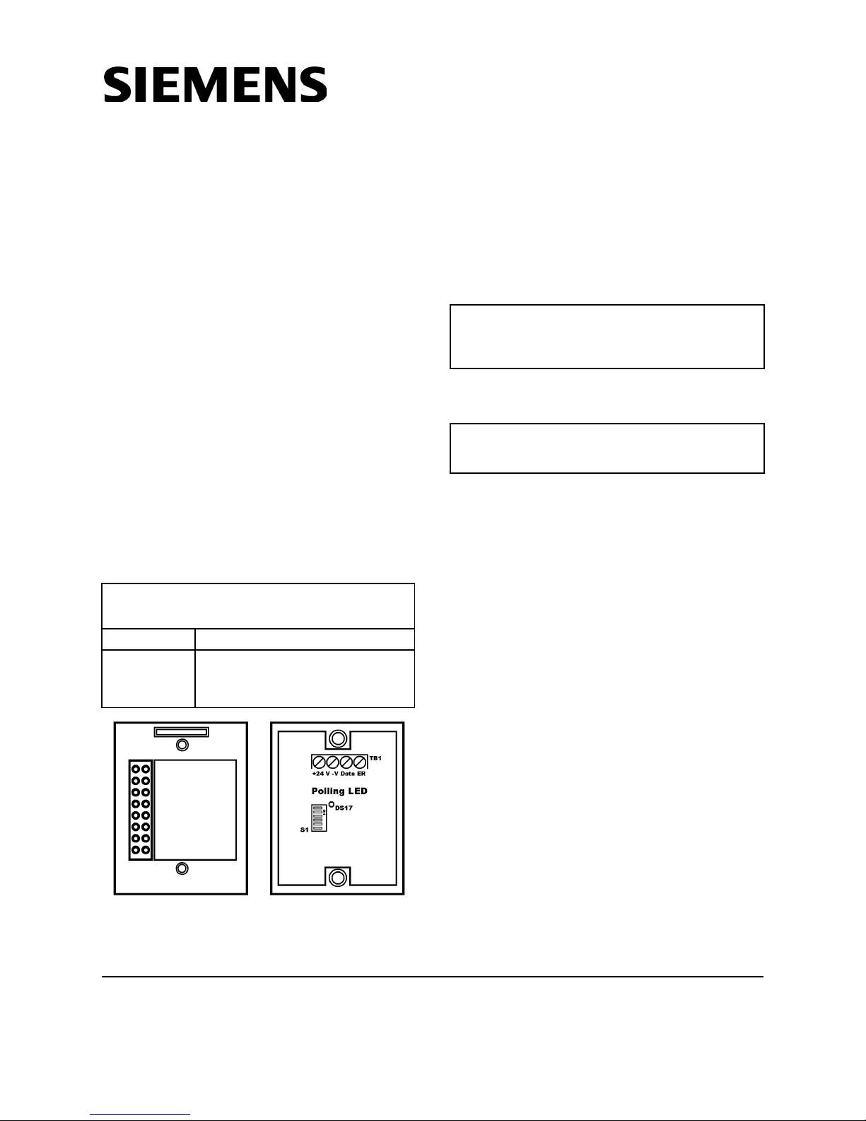
The Model LED-3/4 Remote Annunciator from
Siemens Builidng Technologies, Inc., shown in
Figure 1 is an eight zone annunciator containing
sixteen LEDs. The LEDs can be used to indicate
the alarm, supervisory, or trouble status of
initiating zones.
A maximum of 2 Remote Annunciators can be
added to each SXL-EX system so that the status
of 8 zones can be displayed at two different
locations.
In addition, a green polling LED on the back of
the annunciator indicates the status of the
annunciator when troubleshooting the installation.
ELECTRICAL OPERATING
Input Power 24 VDC (no LEDs on) 10mA
Output
Power
TABLE 1
CHARACTERISTICS
2mA per
ALARM/SUPERVISORY/
TROUBLE LED
42mA max (all LEDs on)
Remove all system power before
installation, first battery and then AC.
(To power up, connect AC first, then the battery.)
INSTALLATION GUIDELINES
Install in accordance with NFPA 72, NEC
Article 760, and any applicable local codes.
ANNUNCIATOR INSTALLATION
Setting the Address for SXL-EX
Set the address of the module using switch S1
located on the back of the module.
To set address 1:
Set SW1 of S1 to OFF
Set SW2-SW6 of S1 to ON
To set address 2:
Set SW2 of S1 to OFF
Set SW1 and SW3-SW6 to ON
Figure 1
LED-3/4 Remote Annunciator
Siemens Building Technologies, Inc.
8 Fernwood Road
Florham Park, New Jersey 07932
P/N 315-093066-11
Any other setting causes a trouble indication on
the panel. There also would be no activity from
the annunciator or from the polling LED, DS17,
which is located next to the S1 switch.
Wiring
Connect the system wiring to the TB1 terminals
BACKFRONT
on the annunciator module. Refer to Table 2,
Table 3, and Figure 2 for proper wiring connections and cable length.
Siemens Building Technologies, Ltd.
2 Kenview Boulevard
Brampton, Ontario L6T 5E4 Canada
1
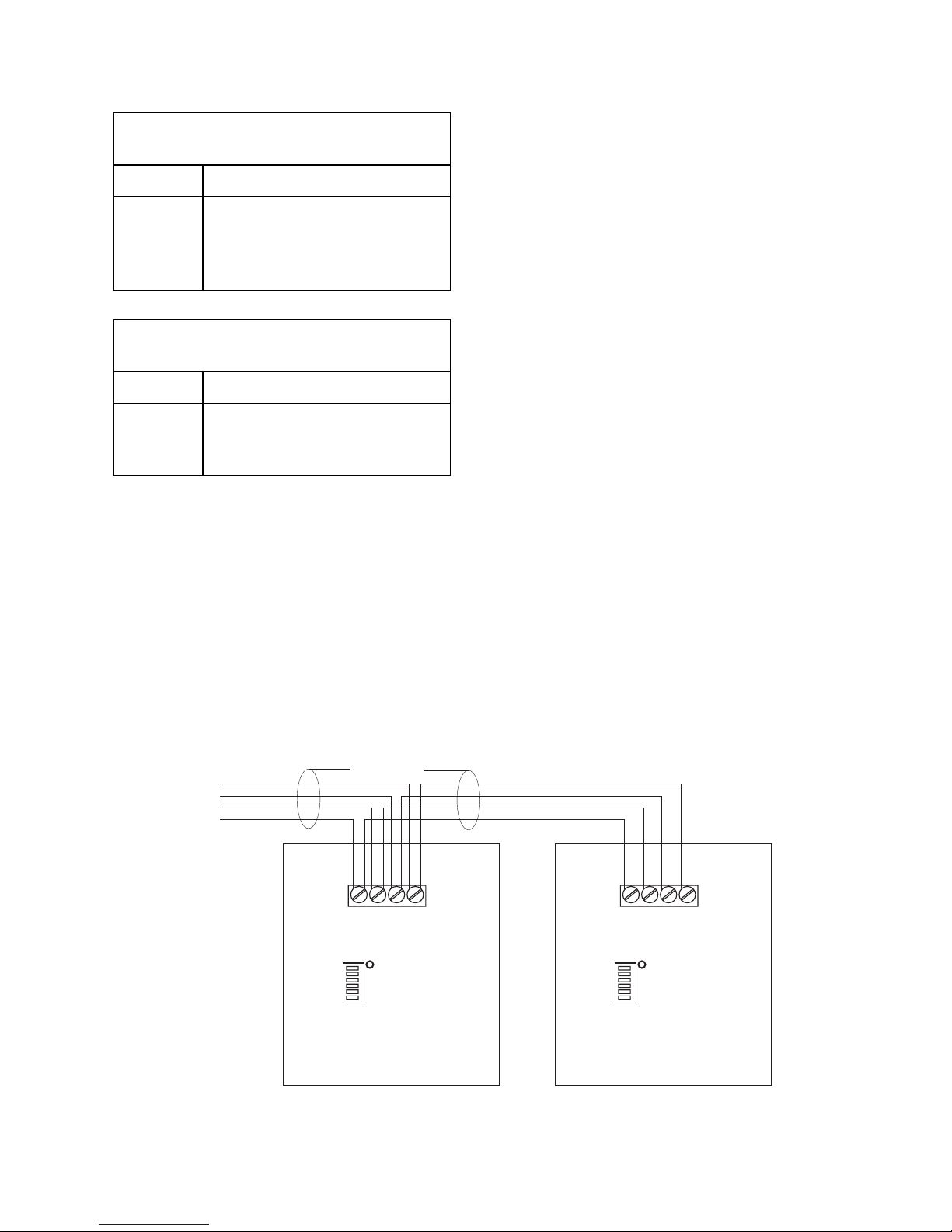
TABLE 2
Terminal Connections
Terminal Function
3. After the system is tested, tighten the mounting screws.
4. Fill in the appropriate information for each
zone on the card provided.
24V
DATA
-V
ER
Provides power to circuitry
Serial communication line
Return line
Earth Return
TABLE 3
Maximum Cable Length vs. Wire Size
AWG Cable Length
14
16
18
Observe the wiring polarity when making connections. Damage may result from incorrect wiring.
2000 feet
2000 feet
1000 feet
Mounting
1. Mount the annunciator semiflush using a
single gang electrical backbox.
2. DO NOT tighten the mounting screws since
the module may have to be removed during
troubleshooting (when looking for activity
from the polling LED, DS17, on the back of
the module.
PROGRAMMING THE SXL-EX SYSTEM
FOR THE LED-3/4 MODULE
Enabling the Program Mode
Enter level 9 of the programming mode.
1. Press the RESET and DRILL keys at the
same time. The TROUBLE LED lights, and
the letter E appears on the seven segment
display.
2. Enter the password by pressing
the appropriate keys:
ACK = 1 DRILL = 3
RESET = 2 SILENCE = 4
Then press the SILENCE key.
The seven segment display either shows F, to
indicate an incorrect password, or A, to
indicate that the password is accepted. If the
letter F appears, repeat Steps 1 and 2. If the
letter A appears, continue to the next step.
3. Press the ACK key once to enter the Program mode. The PROGRAM/TEST LED on
the front panel lights and the
display shows the letter P.
seven segment
To UL listed
SXL-EX
Control Panel
Aux Port TB-3
(Power Limited)
Style 4
Supervised
Positive and Negative
Ground Fault
Detected at <20K for
Terminals on TB-1
Power Limited
+24V -V DATA ER
Polling LED
ON
S1 S1
TB-1 TB-1
Figure 2
LED-3/4 Wiring Connections
2
+24V -V DATA ER
Polling LED
ON
DS17DS17
 Loading...