

Siemens LEC1/8853, LEC1 Series, LEC1/8851, LEC1/8866, LEC1/8867 User Manual
...
CC1N7761E
Grafikname:
Erstellt in:
Erstellt am:
January 1997
7
761
Control Unit
LEC1...
Series 02
Control unit for double or multi-flame supervision of oil, gas or forced draught
oil/gas burners of any fuel throughput (for continuous or intermittent operation).
The LEC1... control unit is designed for the fully automatic start-up and supervision of
those forced draught burners with which the flame supervision should or must be carried
out by separate flame safeguards, e.g. with
- Dual supervision (of the main flame or of the pilot and main flame by means of two
identical or different detectors).
- Supervision of forced draught oil/gas burners (with different types of detectors
according to selected operating mode).
- Multi-flame supervision (i.e. central and simultaneous control of the start-up and
supervision program for several burners, the flames of which, however, must be
individually supervised by one or two flame safeguards each).
The following flame safeguards are available:
LAE10... for the supervision of oil burners with active selenium photocell sensor RAR... in
intermittent operation.
LFE10... for the supervision by means of ionization field (gas burner) or with UVdetectors QRA... (gas, oil or dual fuel burners, with or without ignition spark supervision)
in intermittent operation.
LFE50... for the supervision with UV-detectors QRA50.../51... (gas, oil or dual fuel
burners) in intermittent or continuous operation.
All devices comply with the relevant European standards for oil, gas and forced draught
burners of any fuel throughput.
The LEC1... can control the following burner plant components: fan motor, flue gas fan,
air damper, ignition transformer, one to three fuel valves, the load controller and an
external fault signaling device.
FM739
Use

2 CC1N7761E
The control unit LEC1... as well as the flame safeguards LAE10... and LFE10... are of
plug-in design and are suitable for the mounting in any position at the burner, on control
panels and in control cabinets. The spacious terminal bases and the housings are made
of impact proof and heat-resistant plastic. The switching mechanism of the unit driven by
a synchronous motor, its relays as well as all other switching, control and adjusting
elements are mounted on solid printed circuit boards.
The following description of the mode of operation refers to the start-up and supervision
of one single burner.
With multi-flame supervision all of the burners connected to the control unit are put into
operation and supervised simultaneously in the same manner. A defect leading to a lockout at one of the burners therefore results in the shutdown of all burners. The prerequisite
for the immediate restart of the non-defective burners is the bridging of the flame
safeguard of the defective burner by means of an operating switch. This switch must
simultaneously interrupt all control lines to the ignition transformer and the fuel valves. For
connection examples please refer to data sheet 7781.
The burner is started only if:
- the switching mechanism of the control unit is in its start position
- the control unit is not in lock-out position, e.g. with defective UV-tube
- the contacts of all the control and safety devices in the control loop between
terminal 8 and 9 are closed
- the air pressure monitor does not indicate any air pressure
Defects in the flame safeguard or in the control unit prevent the start or lead to a lock-out
during the start-up.
If the air damper is not controlled by the control unit, terminal 20, 21 and 22 must be
interconnected.
First the fan motor is switched on via terminal 3 and the air damper actuator is driven via
terminal 22. As soon as the air damper has reached its fully open position, the switching
mechanism of the unit starts its run - the prepurge time begins. The minimum air pressure
set at the air pressure monitor must be reached within 10 s (or 7 s in operation with postpurge) and must be maintained until the controlled shutdown, otherwise lockout occurs. A
flame signal during the prepurge time also leads to a lockout. On completion of the set
prepurge time the air damper receives the control command to return to the minimum air
position. During the air damper’s closing time the switching mechanism remains
stationary. As soon as the signal contact for the minimum butterfly position is operated by
the air damper actuator, the switching mechanism starts again and now controls the
program sequence which can no longer be influenced externally:
- Pre-ignition (3 s)
- Release of the 1st fuel valve via terminal 5 (the fuel valve of a pilot burner which must
be closed on completion of the 2nd safety time must, however, be connected to
terminal 10)
- Programming of the set safety time. If no flame is established during this time, lockout
occurs (always with interlocking of the control unit)
- Following an interval of 11 s after the release of the 1st valve, the 2nd fuel valve is
released
- The pilot burner, if connected to terminal 10, is switched off
- The load controller is switched on after a further interval of 12 s. Now the burner has
reached its operating position. From now on the load controller controls the burner
capacity by either increasing or decreasing the fuel throughput and the air volume
depending on the heat demand (fuel/air ratio control). This can be carried out in stages,
i.e. by means of thermostats or continuously (modulating) by using a continuous
controller.
The loss of flame during operation always leads to burner lockout.
Construction of the
Control Unit and the
Flame Safeguards
Operation
Prerequisites for the
burner start-up
Important
Program sequence
during burner start-up
CC1N7761E 3
In principle the program sequence is the same as with burner start-up without ignition
spark supervision. Exceptions:
- If the flame safeguard does not receive any input signal during the short pre-ignition
time (UL2 on position «Short pre-ignition»), lockout occurs before any gas is released,
i.e. safety time t
2 = 0 s.
- With ignition spark supervision the safety time for the pilot burner can only be adjusted
between 0 ... 6 s (in the time diagram of the switching mechanism: t
2z).
Controlled shutdown is carried out as soon as one control or supervision device in the
control loop between terminal 8 and 9 open its contact, i.e. the fuel valves are closed
immediately. The switching mechanism starts again and now programs the post-purge, if
necessary. On completion of the post-purge time the switching mechanism has again
reached its start position in which it remains until the next switching on command is
received.
The flame supervision restarts again during the post-purge time; therefore every flame
signal during this time leads to a lockout.
After actuation of the built-in or external reset button the switching mechanism runs
through to its start position. The only burner plant component which is operated during
this time is a fan motor connected to terminal 17. As the limit thermostat or pressurestat
normally continues to call for heat, the unit immediately initiates a restart as soon as it has
reached its start position.
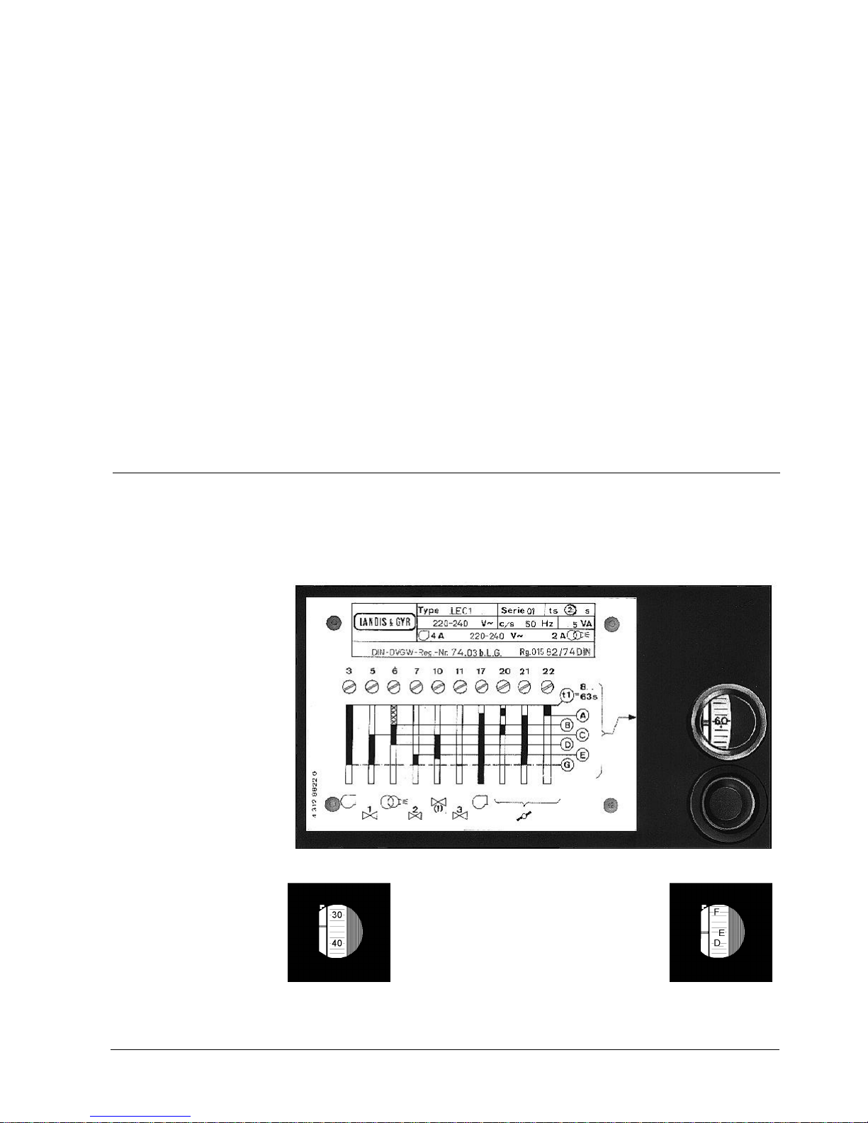
The program indicator continuously shows the respective phase of the burner start-up
sequence. The letters correspond to those of the switching mechanism diagram next to
the viewing window. The figures indicate the remaining pre-purge time. If lockout occurs
the switching mechanism and the program indicator stop and by this means determine
the operating phase during which the lockout occurred.
Í Remaining pre-purge time approx. 35 s
Valve 2 at terminal 7 is opened Î
Burner start-up with
ignition spark
supervision
Control program
following a controlled
shutdown
Control program
following lockout reset
Program Indicator
Reading the program
indicator
4 CC1N7761E
Mains voltage AC 220 V -15%...AC 240 V +10% Radio interference protection
AC 100 V -15%...AC 110 V +10% N according to VDE0875
Mains frequency 50 Hz -6%...60 Hz +6% Max. permissible load on the control outputs
Unit fuse, built-in T6,3H250V − per terminal 4 A
External fuse 10 A max., slow − in total 5 A
Consumption Degree of protection IP40
− during start 8 VA Mounting position optional
− during operation 5 VA Cable gland Pg11
Weight approx. 2 kg
Identification code according to EN 298
F B L L B N
Environmental conditions: CE-Conformity
- Transport IEC721-3-2 According to the directives of the European Community
Climatic conditions class 2K2 Electromagnetic compatibility EMC
Temperature -50...+60 °C 89/336 EWG includ. 92/31 EWG
Humidity < 95 % r.F. Gas appliance directive 90/396 EWG
Mechanical conditions class 2M2 Interfering emissions EN 50081-1
- Operation IEC721-3-3 Immunity against disturbances EN 50082-2
Climatic conditions class 3K5
Temperature -20...+60 °C
Humidity < 95 % r.F.
Condensation, formation of ice and influence of water are not permitted.
LFE10... LFE10... LAE10...
Series 02 Series 02 Series 02
ionization field UV-cell selenium cell
Minimum required detector current in µA
− with AC 100 V and AC 220 V 8 150 8 min.
− with AC 110 V and AC 240 V 9 200 8 min.
Max. possible detector current in µA approx. 100 approx. 650 approx. 25
Permissible connecting cable length 20 m
1)
20 m
1)
20 m
2)
Permissible ambient temperature − 60°C 60°C
1
) In case of larger distances use low capacitance cable, e.g. one-core cable (total 2 nF max.)
2
) Detector cables must always be laid separately, the selenium photocell RAR8 must be used in case of
larger distances
3
) For information on LFE50... please refer to data sheet 7783
Type/Ordering Supply voltage Factory settings for
reference (V) Hz t1 (s) t2 (s) t9 (s)
LEC1/8851 AC 220...240 50 60 2 2
LEC1/8853 AC 220...240 50 30 2 2
LEC1/8866 AC 100...110 50 30 2 2
LEC1/8867 AC 100...110 60 30 2 2
LEC1/8868 AC 220...240 60 30 2 2
LEC1/8892 AC 220...240 50 60 5 5
LEC1/8906 AC 220...240 50 30 2 5
The control unit is delivered without terminal baseplate. The latter must be ordered
separately using the following type reference: AGG41041713 (EC)
For flame safeguards LAE10... and LFE10... as well as the appropriate detectors, please
refer to data sheet 7781.
Technical Data
Control unit LEC1
Flame supervision
3)
Detectors
Type Summary and
Ordering
CC1N7761E 5
Attention: When using the UV-detector QRA... terminal 10 must be connected to earth!
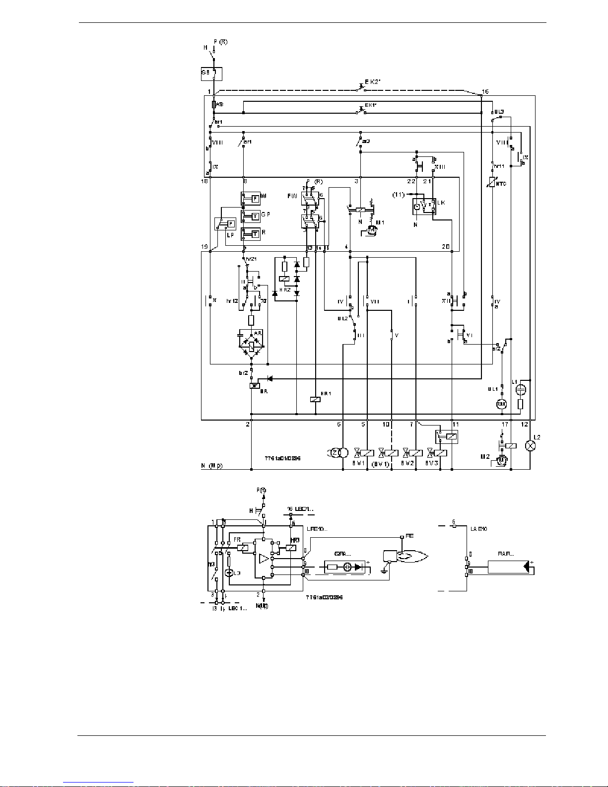
Basic Diagram LEC1
LAE10... and LFE10...
 Loading...