

Siemens LEC1, LEC1/8851, LEC1/8867, LEC1/8866, LEC1/8853 Series Manual
...
CC1N7761en
19.02.2007
Building Technologies
HVAC Products
7
761
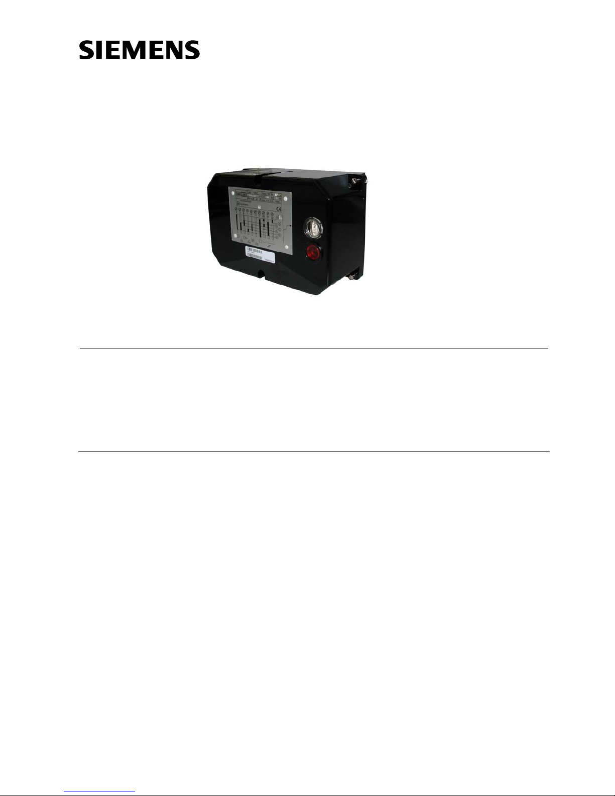
Control Units
LEC1...
Control unit for double- or multiflame supervision of oil, gas or forced draft oil /
gas burners of any fuel throughput, suited for continuous or intermittent operation.
The LEC1... and this Data Sheet are intended for use by OEMs which integrate the
control units in their products!
Use
The LEC1... is designed for the fully automatic startup and supervision of forced draft
oil or gas burners where flame supervision should or must be carried out by separate
flame safeguards, e.g. with:
• Double supervision of the main flame or pilot and main flame by 2 identical or dif-
ferent detectors
• Supervision of forced draft oil / gas burners with different types of detectors, de-
pending on the selected operating mode
• Multiflame supervision, that is, central and simultaneous control of the startup and
supervision sequence of several burners the flames of which must be individually
supervised by 1 or 2 flame safeguards each
Supplementary Data Sheets
• LAE10 Data Sheet N7781
• LFE10 Data Sheet N7781
• LFE50 Data Sheet N7783

2/17
Building Technologies CC1N7761en
HVAC Products 19.02.2007
Use (cont´d)
LAE10 For the supervision of oil burners with an active selenium photocell detec-
tor RAR… in intermittent operation
LFE10 For the supervision with an ionization probe (gas burners) or with UV de-
tectors QRA… (gas, oil or dual-fuel burners, with or without ignition spark
proving) in intermittent operation
LFE50 For the supervision with UV detectors QRA50… / QRA51…(gas, oil or
dual-fuel burners) in intermittent or continuous operation
All units comply with the relevant European standards for oil, gas and forced draft
burners of any fuel throughput.
The LEC1... can control the following burner plant components:
Fan motor, flue gas fan, air damper, ignition transformer, 1 to 3 fuel valves, load controller, and an external fault signaling device.
A load controller with 3-position output can be connected.
Design, control sequence and adjustment facilities of the control unit make it suitable
for use on combustion plants of any size and type, be it in connection with expanding
flame or interrupted pilot burners, continuously operating burners or any other special
burners.
- Prepurge time adjustable between 8 and 63 seconds
- Operation with or without postpurging
- Fully automatic control of air damper possible, irrespective of the actuator run time
- Possibility of air pressure check in connection with functional control of the air
pressure switch prior to startup
- Choice of ignition: Direct ignition with pilot burner, with or without ignition spark
proving
- Preignition time can be set to «Long» (during the prepurge time) or «Short» (3
seconds, e.g. for forced draft gas burners)
- 1st and 2nd safety time adjustable between 0 and 9 seconds
- Automatic extraneous light test during burner off periods and during the purging
times (with lockout in the event of faulty flame signals)
- Semi-automatic burner startup and operation possible
- Built-in lockout warning lamp
- Electrical remote reset facility
- Cover with 2 additional sealing screws to provide protection against tampering
(refer to «Dimensions»)
- Continuous display of the program sequence in the cover’s viewing window
- In the event of a fault, the program indicator shows the operating phase during
which the fault occurred
- Motor of the programming mechanism can be switched off to simplify burner ad-
justments
- Camshaft can be rotated manually
The following types of
flame safeguards are
available:
Special features

3/17
Building Technologies CC1N7761en
HVAC Products 19.02.2007
Warning notes
To avoid injury to persons, damage to property or the environment, the following
warning notes should be observed!
Only authorized staff may open, interfere with or modify the unit!
• All activities (mounting, installation and service work, etc.) must be performed by
qualified staff
• Before performing any wiring changes in the connection area of the LEC1…, com-
pletely isolate the unit from the mains supply (all-polar disconnection)
• Ensure protection against electrical shock hazard by providing adequate protection
for the unit’s terminals
• Each time work has been carried out (mounting, installation, service work, etc.),
check to ensure that wiring is in an orderly state and make the safety checks as
described in «Commissioning notes»
• Press lockout reset button only manually (applying a force of no more than 10 N),
without using any tools or pointed objects
• Fall or shock can adversely affect the safety functions. Such units must not be put
into operation, even if they do not exhibit any damage
• Do not press the lockout reset button on the unit or the remote lockout reset button
for more than 10 seconds since this damages the lockout relay in the unit
Mounting notes
• Ensure that the relevant national safety regulations are complied with
• Locate ignition electrode and ionization probe such that the ignition spark cannot
arc over to the ionization probe (risk of electrical overloads)
Installation notes
• Always run the high-voltage ignition cables separately while observing the greatest
possible distances to the unit and to other cables
• 4 extra terminals for the earth conductor, 4 e xtra terminals for the neutral conductor, and 4 auxiliary terminals
• In the event of loss of flame during operation, the control unit will initiate lockout
• Do not mix up live and neutral conductors
• Install switches, fuses, earthing, etc., in compliance with local regulations
• Observe the maximum permissible current load of the connecting terminals
4/17
Building Technologies CC1N7761en
HVAC Products 19.02.2007
Electrical connection of the flame detectors
It is important to achieve practically disturbance- and loss-free signal transmission:
• Never run the detector cable together with other cables
– Line capacitance reduces the magnitude of the flame signal
– Use a separate cable
• Observe the maximum permissible lengths of the detector cables (refer to «Techni-
cal data» at current flame safeguards
• The ionization probe is not protected against electric shock hazard
• Locate the ignition electrode and ionization probe such that the ignition spark can-
not arc over to the ionization probe (risk of electrical overloads) and a override of
ionization supervision via ignition spark must be avoided
• Insulation resistance
– Must be a minimum of 50 MΩ between ionization probe and ground
– Soiled detector holders reduce the insulation resistance, thus supporting
creepage currents
• Earth the burner in compliance with the relevant regulations; earthing the boiler
alone does not suffice
Commissioning notes
• Continuous display of the program sequence in the viewing window:
It is also possible to program the unit by means of a changeover link (UL3) in a way
that the programming mechanism does not stop in case of lockout, but that it runs
to the end of the program. The only component that receives power during that period of time is the fan for postpurging (connected to terminal 17)
• The motor of the programming mechanism can be switched off (simplifies burner
adjustments)
• The camshaft can be rotated manually
• For setting instructions, refer to «Adjustment facilities on the unit»
• When commissioning the plant or when carrying out maintenance work, make the
following checks:
Safety check Anticipated response
a) Burner startup with flame detector darkened Lockout at the end of
«TSA»
b) Burner startup with flame detector exposed to
extraneous light
Lockout after no more than
40 seconds
c) Burner operation with simulated loss of flame Immediate lockout
d) Burner startup with open-circuit of air pressure
switch (not with atmospheric burners)
Lockout at the end of the
specified time «t10»
e) Burner operation with simulated air pressure
failure (not with atmospheric burners)
Immediate lockout
Standards and certificates
Conformity to ECC directives
- Electromagnetic compatibility EMC (immunity)
- Directive for gas appliances
– Low-voltage directive
89 / 336 / EEC
90 / 396 / EEC
73 / 23 / EEC
ISO 9001: 2000
Cert. 00739
ISO 14001: 2004
Cert. 38233
• Identification code to EN298 F B L L B N
5/17
Building Technologies CC1N7761en
HVAC Products 19.02.2007
Disposal notes
The unit contains electric and electronic components and must not be disposed of as
household waste.
Local and currently valid legislation must be observed.
Mechanical design
The LEC1... as well as the flame safeguards LAE10 and LFE10 are of plug-in design
and suitable for mounting in any position on the burner, on control desks or in control
panels.
The spacious terminal bases and housings are made of impact-proof and heat-resistant
plastic.
The programming mechanism of the unit (driven by a synchronous motor), its auxiliary
relays and all other switching, control and adjusting elements are mounted on robust
printed circuit boards.
Type summary and ordering
Factory settings for Type reference * Rated voltage
mains
frequency
t1 TSA t9
LEC1 / 8851 AC 220...240 V 50 Hz 60 s 2 s 2 s
LEC1 / 8853 AC 220...240 V 50 Hz 30 s 2 s 2 s
LEC1 / 8866 AC 100...110 V 50 Hz 30 s 2 s 2 s
LEC1 / 8867 AC 100...110 V 60 Hz 30 s 2 s 2 s
LEC1 / 8868 AC 220...240 V 60 Hz 30 s 2 s 2 s
LEC1 / 8892 AC 220...240 V 50 Hz 60 s 5 s 5 s
LEC1.1 / 8854 AC 220...240 V 50 Hz 17 s 2 s 2 s
LEC1 / 9500 AC 230 V 60 Hz 60 s 4.5 s 4.5 s
LEC1 / 9501 AC 100...110 V 50 Hz 60 s 4.5 s 4.5 s
LEC1 / 9502 AC 100...110 V 60 Hz 60 s 4.5 s 4.5 s
LEC1 / 9503 AC 230 V 50 Hz 60 s 4.5 s 4.5 s
The control unit is delivered without terminal base.
The latter must be ordered as a separate item using the following part number:
AGG41041713 (EC) or AGG12.1
* The type reference is given near the terminals inside the housing
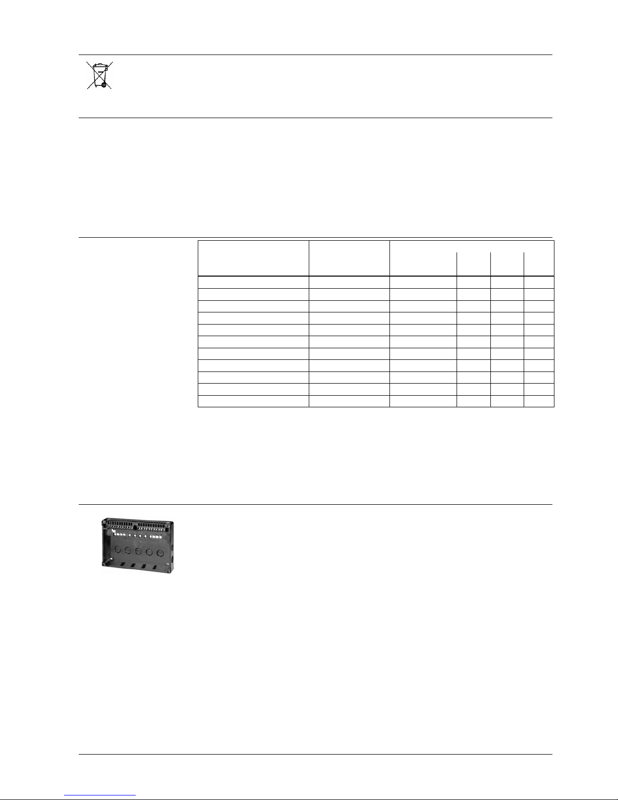
Accessories
Terminal base AGG41041713 (EC)
- To be ordered as a separate item
- For Pg 11
Terminal base AGG12.1
- To be ordered as a separate item
- For M16 x 1.5
6/17
Building Technologies CC1N7761en
HVAC Products 19.02.2007
Technical data
Mains voltage AC 220 V -15 %...AC 240 V +10 %
AC 100 V -15 %...AC 110 V +10 %
Mains frequency 50...60 Hz ±6 %
Unit fuse, built-in T6.3H250V to DIN EN 60 127
External fuse max. 10 A (slow)
Power consumption
- During startup
- During operation
8 VA
5 VA
Permissible load on the control outputs
- Per terminal
- Total
max. 4 A to VDE 0660 AC3
max. 5 A to VDE 0660 AC3
Degree of protection IP 40 (to be ensured through mounting)
Mounting position Optional
Cable glands - Pg11 or
- BSP ¾“ or
- metric M16 x 1.5
Weight approx. 2 kg
Storage
DIN EN 60721-3-1
Climatic conditions class 1K3
Mechanical conditions class 1M2
Temperature range -20...+60 °C
Humidity < 95 % r.h.
Transport
DIN EN 60 721-3-2
Climatic conditions class 2K2
Mechanical conditions class 2M2
Temperature -50...+60 °C
Humidity < 95 % r.h.
Operation
DIN EN 60 721-3-3
Climatic conditions class 3K5
Mechanical conditions class 3M2
Temperature -20...+60 °C
Humidity < 95 % r.h.
Condensation, formation of ice and ingress of water are not permitted!
• With LAE10
• With LFE10
• With LFE50
General unit data
Environmental
conditions
Flame supervision
 Loading...