

Siemens LDS 6 Operating Instructions Manual
LDS 6
In-situ Laser Gas Analyzer
•
Operating Instructions
LDS 6 In-situ Laser Gas Analyzer
01/2009
Operating Instructions • 01/2009
Continuous Gas Analysis

General Information
1
Technical Information
2
Installation Guidelines
3
Operation
4
Alarms
5
Maintenance and Service
6
Spare Parts List
7
Technical Data
8
Dimensional Drawings
9
ESD guidelines
A
List of Abbreviations
B
Continuous Gas Analysis
In Situ Laser Gas Analyzers
LDS 6
Operating Instructions
01/2009
A5E00295894-05
Legal information
Warning notice system
This manual contains notices you have to observe in order to ensure your personal safety, as well as to prevent
damage to property. The notices referring to your personal safety are highlighted in the manual by a safety alert
symbol, notices referring only to property damage have no safety alert symbol. These notices shown below are
graded according to the degree of danger.
DANGER
indicates that death or severe personal injury will result if proper precautions are not taken.
WARNING
indicates that death or severe personal injury may result if proper precautions are not taken.
CAUTION
with a safety alert symbol, indicates that minor personal injury can result if proper precautions are not taken.
CAUTION
without a safety alert symbol, indicates that property damage can result if proper precautions are not taken.
NOTICE
indicates that an unintended result or situation can occur if the corresponding information is not taken into
account.
If more than one degree of danger is present, the warning notice representing the highest degree of danger will
be used. A notice warning of injury to persons with a safety alert symbol may also include a warning relating to
property damage.
Qualified Personnel
The device/system may only be set up and used in conjunction with this documentation. Commissioning and
operation of a device/system may only be performed by qualified personnel. Within the context of the safety notes
in this documentation qualified persons are defined as persons who are authorized to commission, ground and
label devices, systems and circuits in accordance with established safety practices and standards.
Proper use of Siemens products
Note the following:
WARNING
Siemens products may only be used for the applications described in the catalog and in the relevant technical
documentation. If products and components from other manufacturers are used, these must be recommended
or approved by Siemens. Proper transport, storage, installation, assembly, commissioning, operation and
maintenance are required to ensure that the products operate safely and without any problems. The permissible
ambient conditions must be adhered to. The information in the relevant documentation must be observed.
Trademarks
All names identified by ® are registered trademarks of the Siemens AG. The remaining trademarks in this
publication may be trademarks whose use by third parties for their own purposes could violate the rights of the
owner.
Disclaimer of Liability
We have reviewed the contents of this publication to ensure consistency with the hardware and software
described. Since variance cannot be precluded entirely, we cannot guarantee full consistency. However, the
information in this publication is reviewed regularly and any necessary corrections are included in subsequent
editions.
Siemens AG
Industry Sector
Postfach 48 48
90026 NÜRNBERG
GERMANY
Ordernumber: A5E00295894
Ⓟ 04/2009
Copyright © Siemens AG 2004,
2007, 2008, 2009.
Technical data subject to change

LDS 6
Operating Instructions, 01/2009, A5E00295894-05
5
Content
1 General Information
................................................................................................................................... 7
1.1 Information for our
Customers .......................................................................................................7
1.2 General Information
.......................................................................................................................7
1.3 Special Information and
Warnings.................................................................................................8
1.4 Warranty Conditions ......................................................................................................................8
1.5 Delivery Information .......................................................................................................................8
1.6 Standards and Regulations............................................................................................................8
2 Technical Inf
ormation ................................................................................................................................ 9
2.1 General Description
.......................................................................................................................9
2.2 Design..........................................................................................................................................13
2.3 Operating Principle ......................................................................................................................19
2.4 Configuration Examples...............................................................................................................20
2.5 Measurement Princ
iple ................................................................................................................21
3 Installation Guidelines
.............................................................................................................................. 25
3.1 Safety Information........................................................................................................................25
3.2 General Installation Information
...................................................................................................28
3.3 Electrical Connections .................................................................................................................29
3.3.1 Power Supply Connections
..........................................................................................................29
3.3.2 Hybrid Cable Connection.............................................................................................................31
3.3.3 Signal Cable Connection
.............................................................................................................32
3.3.4 Pin Assignment of LDS 6 .............................................................................................................34
3.4 Three Channel System ................................................................................................................35
3.4.1 External Power Suppl
y.................................................................................................................35
3.4.2 Three Channel Hybrid Cable Connec
tion....................................................................................36
3.5 Flange Installation Requirements
................................................................................................37
3.6 Installation of
Flanges ..................................................................................................................37
4 Operation
................................................................................................................................................. 41
4.1 General ........................................................................................................................................41
4.2 Input Sequence of Data
...............................................................................................................44
4.3 Analyzer Functions ......................................................................................................................47
4.3.1 Summary of Analyzer Functions..................................................................................................47
4.3.2 Analyzer Status............................................................................................................................49
4.3.3 Calibration
....................................................................................................................................51
4.3.4 Measuring Ranges.......................................................................................................................52
4.3.5 Parameters...................................................................................................................................52
4.3.6 Configuration................................................................................................................................55

Content
LDS 6
6 Operating Instructions, 01/2009, A5E00295894-05
4.4 Watch Dog................................................................................................................................... 64
5 Alarms ..................................................................................................................................................... 65
5.1 Alarm Response.......................................................................................................................... 65
5.2 Maintenance Request Alarm....................................................................................................... 67
5.3 Faults Alarm ................................................................................................................................ 68
5.4 Transmission Alarm .................................................................................................................... 69
5.5 Limit Alarm
.................................................................................................................................. 69
5.6 Function control alarm
................................................................................................................. 69
6 Maintenance and Servi
ce ........................................................................................................................ 71
6.1 General about Maintenance and Servi
ce.................................................................................... 71
6.2 Cleaning the Central Unit
............................................................................................................ 71
6.3 Cleaning the Wedge Windows
.................................................................................................... 71
6.4 Calibration Verification ................................................................................................................ 72
6.5 Reconfiguration of Temperature Compens
ation......................................................................... 73
6.6 Reconfiguration of Press
ure Compensation ............................................................................... 74
6.7 Reconfiguration of the Path Length
............................................................................................ 75
7 Spare Parts List....................................................................................................................................... 77
7.1 Compatibility of detectors
with central units................................................................................ 77
7.1.1 Detector Labels ........................................................................................................................... 77
7.1.2 Central Unit Label
s...................................................................................................................... 78
7.2 Spare Parts Lists......................................................................................................................... 79
7.3 Ordering Instructions................................................................................................................... 81
7.4 Repair/Upgrade........................................................................................................................... 81
8 Technical
Data......................................................................................................................................... 83
8.1 Central Unit
................................................................................................................................. 83
8.2 Hybrid and Sensor Cables
.......................................................................................................... 87
8.3 Purging........................................................................................................................................ 88
9 Dimensional Dra
wings ............................................................................................................................. 89
A ESD guidelin
es ........................................................................................................................................ 93
A.1 ESD guidelines............................................................................................................................ 93
B List of Abbre
viations ................................................................................................................................ 95
B.1 List of Abbreviations
.................................................................................................................... 95
Index........................................................................................................................................................ 99

LDS 6
Operating Instructions, 01/2009, A5E00295894-05
7
General Information
1
1.1 Information for our Customers
Before beginning work with this device, please study this manual carefully! It contains
important information and data whose observation ensures proper device function and saves
you servicing costs. The manual will help you to operate the device more easily and
efficiently, allowing you to achieve reliable results.
1.2 General Information
The product described in this manual has left the factory in a high quality and tested
condition. In order to preserve this condition and to operate this product correctly and safely,
it may only be used in the manner described by the manufacturer. Furthermore, proper
transportation, storage, installation, operation and maintenance of the device is vital for
ensuring correct and safe operation.
This manual contains the information required for the intended use of the described product.
It is addressed to technically qualified personnel who are specially trained or who have the
relevant knowledge of automation technology (measuring and control systems).
Knowledge and technically correct implementation of the safety notes and warnings
contained in this manual are required for safe installation and commissioning, as well as for
safety during the operation and maintenance of the described product. Only qualified
personnel have the required professional knowledge for correctly interpreting the generally
valid safety notes and warnings in this manual in each specific case and to act accordingly.
This manual is an inherent part of the scope of delivery, despite the fact that it can be
ordered separately for logistic reasons.
Due to the variety of technical details, it is not possible to consider every single detail for all
versions of the described product and for every conceivable case in the set-up, operation,
maintenance and use in systems. For further information, or in the case of problems which
are not covered in enough detail in this document, please request the required information
from your local or responsible Siemens regional office.
Note
In particular, before using the device for new research and development applications, we
recommend that you first contact your Siemens representative or our application department
to discuss the application in question.

General Information
1.3 Special Information and Warnings
LDS 6
8 Operating Instructions, 01/2009, A5E00295894-05
1.3 Special Information and Warnings
This manual provides you with information on using, installing, operating, and maintaining
the device.
Pay particular attention to all special information and warnings. Information of this type is set
apart from the rest of the text and is marked with the corresponding pictograms. This
information provides you with useful tips and helps to avoid faulty operation.
1.4 Warranty Conditions
We expressly point out that the product quality is exclusively and conclusively described in
the sales contract. The content of this product documentation is neither a part of a previous
or existing agreement, promise or legal relationship, nor is it intended to modify these. All
obligations on the part of Siemens AG are contained in the respective sales contract, which
also contains the complete and solely applicable liability provisions. The provisions defined
in the sales contract for the responsibility for defects are neither extended nor limited by the
remarks in this document.
1.5 Delivery Information
The respective scope of delivery is listed on the shipping documents – enclosed with the
delivery – in accordance with the valid sales contract.
When opening the packaging, please observe the corresponding information on the
packaging material. Check the delivery for completeness and undamaged condition. In
particular, you should compare the Order No. on the rating plates with the ordering data, if
available.
If possible, please retain the packaging material, since you can use it again in case of return
deliveries.
1.6 Standards and Regulations
As far as possible, the harmonized European standards were the basis for the specification
and production of this device. If no harmonized European standards have been applied, the
standards and regulations for the Federal Republic of Germany are valid.
When this product is used beyond the scope of these standards and regulations, the valid
standards and regulations of the country of the operating company apply.
LDS 6
Operating Instructions, 01/2009, A5E00295894-05
9
Technical Information
2
2.1 General Description
Overview
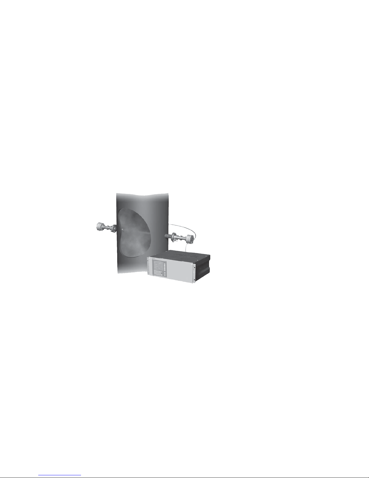
LDS 6 is a diode laser gas analyzer with a measuring principle based on the specific light
absorption of different gas components. LDS 6 is suitable for fast and non-contact
measurement of gas concentrations or temperatures in process or flue gases. One or two
signals from up to three measuring points are processed simultaneously by one central
analyzer unit. The in-situ cross-duct sensors at each measuring point can be separated up to
700 m from the central unit by using fiber-optic cables. The sensors are designed for
operation under harsh environmental conditions and contain a minimum of electrical
components.
Figure 2-1 LDS 6, typical installation with transmitted-light sensors

Technical Information
2.1 General Description
LDS 6
10 Operating Instructions, 01/2009, A5E00295894-05
Benefits
The in-situ gas analyzer LDS 6 is characterized by a high availability and unique analytical
selectivity, and by a broad scope of suitable applications. LDS 6 enables the measurement
of one or two gas components or – if desired – the gas temperature directly in the process:
● With high levels of dust load
● In hot, humid, corrosive, explosive, or toxic gases
● In applications showing strong varying gas compositions
● Under harsh environmental conditions at the measuring point
● Highly selective, i.e. mostly without cross-sensitivities
LDS 6 properties:
● Little installation effort
● Minimum maintenance requirements
● Extremely rugged design
● High long-term stability through built-in, maintenance-free reference gas cell, field
calibration is unnecessary
● Real-time measurements
Moreover, the instrument provides warning and failure messages upon:
● Need for maintenance
● Erroneous reference function
● Bad signal quality
● Exceeding of a lower or upper alarm level for the measured variable
● Transmitted amount of light exceeding an upper or lower limit

Technical Information
2.1 General Description
LDS 6
Operating Instructions, 01/2009, A5E00295894-05
11
Application
The LDS 6 laser gas analyzer is suitable for a wide range of applications. The most common
of them are:
● Process optimization
● Continuous emission monitoring for all kinds of fuels (oil, gas, coal, and others)
● Process measurements in power utilities and any kind of incinerator
● Process control
● Explosion protection
● Measurements in corrosive and toxic gases
● Quality control
● Environmental protection
● Plant and operator safety
Sectors
● Power plants
● Steel works
● Cement industry
● Chemical and petrochemical plants
● Automotive industry
● Waste incinerators
● Glass and ceramics production
● Research and development
Special applications
In addition to the standard applications, special applications are available upon request.

Technical Information
2.1 General Description
LDS 6
12 Operating Instructions, 01/2009, A5E00295894-05
Essential characteristics
● Integrated calibration adjustment with an internal reference cell
● Negligible long-term drifts of zero and span
● Dynamic background correction for varying dust loads
● Isolated signal outputs, 4 to 20 mA
● User-friendly, menu-driven operation
● Selectable time constants (response time)
● Two user levels with individual access codes for prevention of unwanted and
unauthorized operations
● Operation according to NAMUR recommendations
● Monitoring of overall optical transmission
● Remote preventive maintenance and servicing via Ethernet/modem
● Straightforward replacement of the central unit, since connections can easily be removed
● Sensor and central unit housing free of wear and corrosion
● Easy operation with a numerical keypad and menu prompting
Certified versions for emission monitoring
The LDS 6 is available as certified instrument for emission monitoring of NH3, NH3/H2O, H2O,
HCl, HCl/H
2
O. The certificates are issued by TÜV for Germany and MCERTS for the United
Kingdom. For conducting regular linearity and calibration checks, test kits for ammonia,
water and HCl should be used. These kits can be ordered separately as instrument
accessories. For new analyzer orders, the NH
3
, NH3/H2O and H2O kits named "Version 2"
must be ordered. In case of doubt or for already installed analyzers, please contact Siemens
for spotting the correct kit version.
Technical Information
2.2 Design
LDS 6
Operating Instructions, 01/2009, A5E00295894-05
13
2.2 Design
The gas analyzer LDS 6 consists of a central unit and up to three in-situ sensors. The
connection between the central unit and the sensors is established by a so-called hybrid
cable, which contains optical fibers and copper wires. An additional cable connects the
transmitter and receiver parts of the cross-duct sensor.
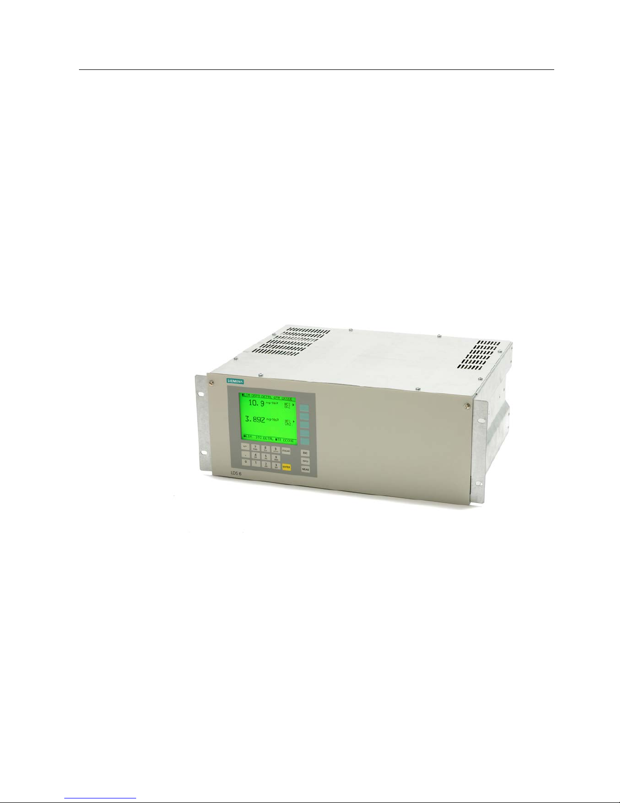
Central unit
The central unit is housed in a 19" rack with 4 holders for mounting in a hinged frame in
racks with or without telescopic rails.
The LDS 6 operates as an independent unit powered by a 100-240 V AC main power supply.
Figure 2-2 CentralUnit
Technical Information
2.2 Design
LDS 6
14 Operating Instructions, 01/2009, A5E00295894-05
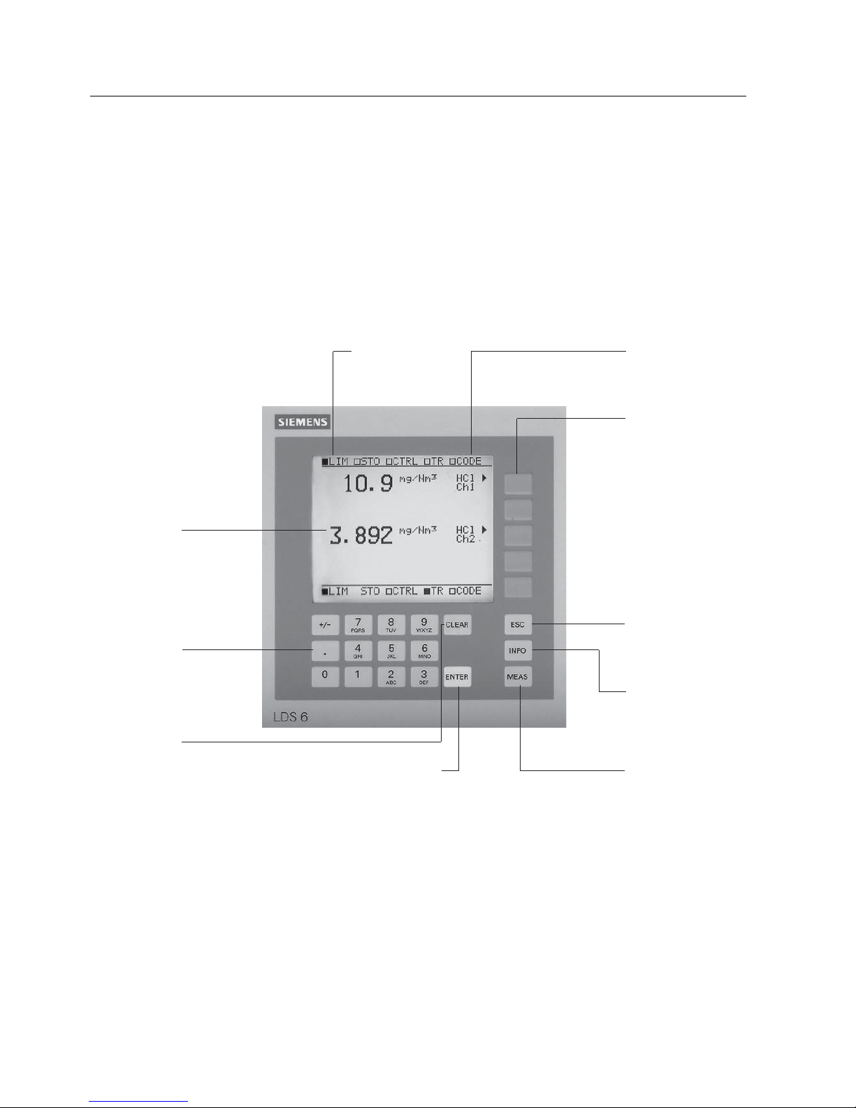
Display and control panel
● Large LCD field for simultaneous display of measurement result and device status
● Contrast of the LCD field is adjustable via the menu
● LED background illumination of the display with energy-saving function
● Easy-to-clean membrane touch pad with softkeys
● Menu-driven operation for parameterization and diagnostics
● Operation support in plain text
6WDWXVOLQHWRLQGLFDWH
WKHGHYLFHVWDWXV
/('EDFNOLWJUDSKLF
GLVSOD\DQGPHPEUDQH
WDFWLOHWRXFKNH\ERDUG
7ZRFRGHOHYHOV
DFFRUGLQJWR1$085
0($6NH\
WRUHWXUQGLUHFWWR
PHDVXUHPHQWPRGH
0HQXGULYHQ
RSHUDWRUFRQWURO
ZLWKILYHVRIWNH\V
(6&NH\
WRFDQFHOHQWULHV
,1)2NH\
IRUKHOSLQSODLQWH[W
&/($5NH\
WRGHOHWHWKH
GLJLWVHQWHUHG
1XPHULFNH\SDG
IRUHQWHULQJGLJLWV
1XPHULFGLVSOD\
RIFRQFHQWUDWLRQV
(17(5NH\
WRDGRSW
WKHQXPEHUV
Figure 2-3 LDS 6 central unit, membrane keyboard and graphic display

Technical Information
2.2 Design
LDS 6
Operating Instructions, 01/2009, A5E00295894-05
15
Inputs and outputs
● One to three measurement channels with hybrid connections for the sensors at the
measuring points
● Two analog inputs per channel for process gas temperature and pressure
● Two analog outputs per channel for gas concentration(s) or for gas temperature and
concentration For selected versions, the transmission can be read out as an alternative.
● Six freely configurable binary inputs per channel for signalling faults or maintenance
requests from external temperature or pressure transducers or sensor purging failure.
● Six freely configurable binary outputs per channel (signalling of faults, maintenance
requirements, function control, transmission limit alarms, concentration limit alarms, store
analog output)
Communication
Network connection: Ethernet (10Base-T) for remote diagnostics and maintenance.
The LDS 6 can be operated remotely via the Ethernet port with a PC running
Windows 95/98/ME or Windows NT/2000/XP. It is also possible to connect the LDS 6 via
modem to the public telephone net. In that case an LDS 6 LAN modem kit is required. Any
external connection requires the optional software LDSComm (LDS Communication Client)
to be installed on the remote computer. All aspects of LDS 6 can be controlled in this way.
For the operation of the LDS 6 using LDSComm software refer to the LDSComm Manual
(A5E02183317).
Maintenance and fault messages
LDS 6 outputs different warnings via relays:
● Need for maintenance (measured value is not influenced)
● Operating error (measured value might be influenced)
Technical Information
2.2 Design
LDS 6
16 Operating Instructions, 01/2009, A5E00295894-05
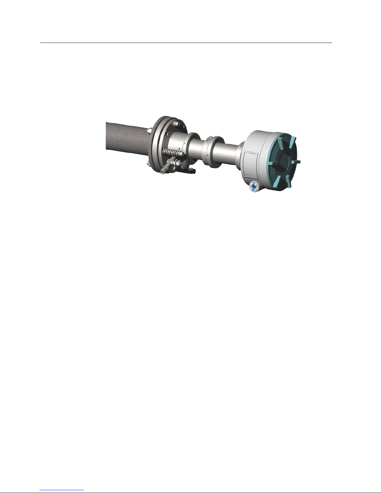
Cross-duct sensors
Figure 2-4 Sensor CD 6, transmitter or receiver unit
● In-situ cross-duct sensors, configured as transmitter and receiver unit, connected via
sensor cable
● Connection to the LDS 6 central unit by a so-called hybrid cable, max. length 700 m
● Stainless steel, partially painted
● IP65 degree of protection for sensor
● Adjustable flanges with flange connection
DN 65/PN 6, ANSI 4"/150 lbs
● Optional flameproof window flanges with dimensions: DN 65/PN 6, DN 80/PN 16, ANSI
4"/150 lbs, other process interfaces available on request
● Purging facilities on the process and the sensor sides, configurable application with
purging gas connections for:
– Instrument air
– Purging air blower
– Steam
– Nitrogen
– Process gases to which the pressure equipment directive cat. 2 does not apply
● In combination with high-pressure window flanges, purging with instrument air or nitrogen
is possible
● Fast connectors for cleaning the measurement openings and the sensor window

Technical Information
2.2 Design
LDS 6
Operating Instructions, 01/2009, A5E00295894-05
17
● Optional: Ex-protected version according to
ATEX II 1GD T135 °C EEx ia IIC T4, Cert. No. DEMKO 06 ATEX 139648X. Certificates
according to IEC and TIIS are also available
● Sensor types CD 6 and CD 6C are compliant with the pressure equipment directive
Note
The sensors are described in detail in separate manuals which is part of their delivery.
ATEX sensors
The sensors are also available in an ATEX version - see also separate user manual. These
have very low power electronics and are intrinsically safe. For use in areas with potentially
explosive atmosphere a barrier box must be installed additionally.
For further information regarding the ATEX option please refer to the separate ATEX manual
for LDS 6.
Parts in contact with the process gases
The sensors normally do not come into contact with the process gas, since purging with a
gaseous media is applied at the process side. Stainless steel purging gas tubes in front of
the sensor windows immerse slightly into the process gas and thus limit the purging volume.
Special materials such as Hastelloy, plastics (PP) and ceramics are available on request.
Technical Information
2.2 Design
LDS 6
18 Operating Instructions, 01/2009, A5E00295894-05
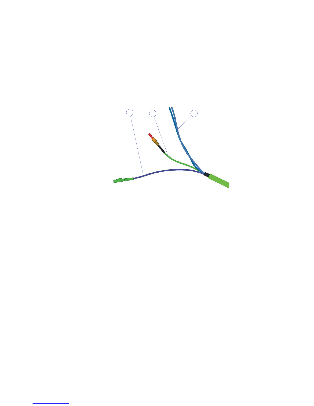
Hybrid and sensor cables
A combination of fiber-optic cables and twisted copper wires connects the sensors to the
central unit. The hybrid cable connects the central unit with the transmitter unit of the sensor,
the sensor cable connects the transmitter and receiver units of the sensor.
2
1
3
1 Twisted pair of wires
2 Multimode fiber
3 Singlemode fiber
Figure 2-5 Connections of the hybrid cable
For installation in EEx-protected environments, the legislative regulations have to be
complied with, such as the spatial separation of intrinsically-safe from non-intrinsically-safe
cables.
● Max. 700 m between central unit and measuring point
● Hybrid and sensor cables
– Multimode fiber-optic cable, provided with SMA connections for transmission of the
measured signal
– Two-wire copper cable, in twisted pair version, for +24 V supply of the detector
electronics (+12 V in the case of EEx-suitable instruments)
● Additionally for the hybrid cable:
– Single-mode fiber-optic cable, configured double-sided with E2000 connectors for
transmission of laser light
● Rugged cable sheath for mounting in open cable ducts or ductworks
● Sheath material: oil-resistant polyurethane
Technical Information
2.3 Operating Principle
LDS 6
Operating Instructions, 01/2009, A5E00295894-05
19
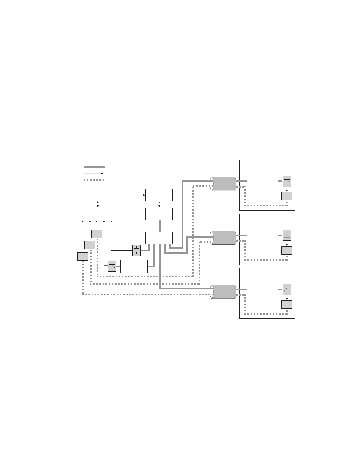
2.3 Operating Principle
LDS 6 is a gas analyzer employing single-line molecular absorption spectroscopy. A diode
laser emits a beam of near-infrared light, which passes through the process gas and is
detected by a receiver unit. The wavelength of the laser diode output is tuned to a gasspecific absorption line. The laser continuously scans this single absorption line with a very
high spectral resolution.
The result is a fully resolved single molecular line which is analyzed in terms of absorption
strength and line shape. The influence of cross-sensitivities on the measurement is
negligible, since the quasi-monochromatic laser light is absorbed very selectively by only one
specific molecular line in the scanned spectral range.
3
7
3
7
3
7
3
7
3
7
0HDVXUHG
YROXPH
(2
&KDQQHO
/DVHU
FRQWURO
'LRGH
ODVHU
2SWRFRXSOHU
5HIHUHQFH
FHOO
&38DQG
GLVSOD\
6LJQDO
SURFHVVLQJ
/DVHUOLJKW
(OHFWULFDOVLJQDOV
5HIOHFWHG/('OLJKW
&HQWUDOXQLW +\EULGFDEOHV 0HDVXUHPHQWSDWK
(2
(2
(2
0HDVXUHG
YROXPH
0HDVXUHG
YROXPH
&KDQQHO
&KDQQHO
(2
(2
Figure 2-6 Basic design of the LDS 6
Technical Information
2.4 Configuration Examples
LDS 6
20 Operating Instructions, 01/2009, A5E00295894-05
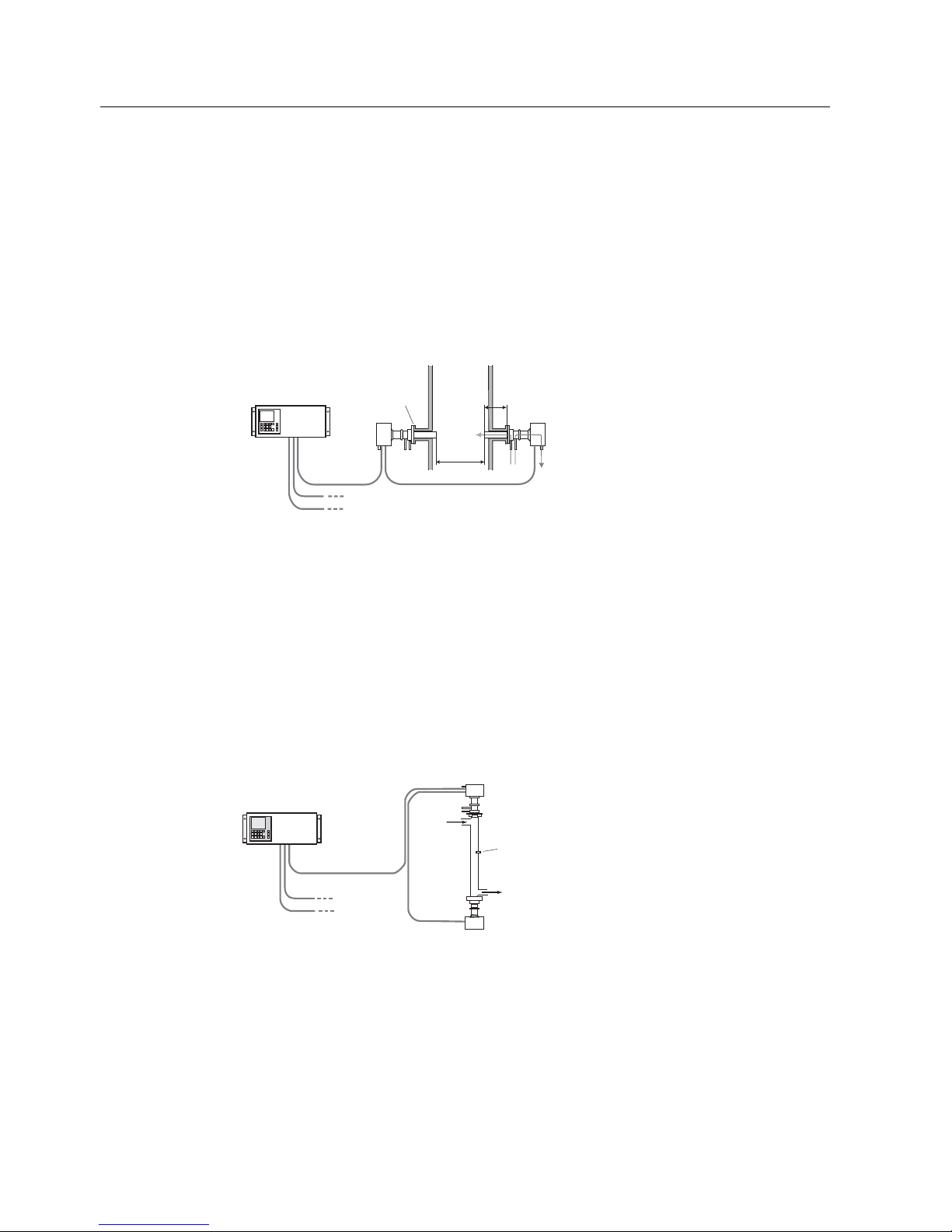
2.4 Configuration Examples
A feature of the in-situ analytical procedure is that the physical measurement takes place
directly in the stream of process gas, and usually also directly in the actual process gas line.
All process parameters such as gas matrix, pressure, temperature, moisture, dust load, flow
velocity and mounting orientation can influence the measuring properties of the LDS 6 and
must therefore be systematically investigated for each new application.
&HQWUDOXQLW
+\EULGFDEOH
PD[OHQJWKP
6XSSOHPHQWDU\FKDQQHORSWLRQ
6XSSOHPHQWDU\FKDQQHORSWLRQ
7UDQVPLWWHUXQLW
5HFHLYHU
3URFHVVIODQJH
6HQVRUFRQQHFWLQJFDEOH
0HDVXUHPHQW
SDWKOHQJWK
*DVFRQFHQWUDWLRQ
)OXHJDV
FRPSRVLWLRQ
6WHDP
'XVWORDG
*DVYHORFLW\
*DVWHPSHUDWXUH
*DVSUHVVXUH
Figure 2-7 Typical transmitted light setup of LDS 6, in-situ
A feature of the standard applications defined in the ordering data of the LDS 6 is that the
typical process conditions are well-known and documented, and that the guaranteed
measuring properties can be proven by reference installations. If you cannot find your
application among the standard applications, please contact Siemens. We will be pleased to
check your possible individual application of the LDS 6. You can find an application
questionnaire on the LDS product sites on the Internet.
To avoid contamination of sensor openings on the process side, clean gaseous purging
media are used such as instrument air, N
2
or steam. Purging air tubes on the sensor heads,
which slightly penetrate into the process gas stream, define the effective measuring path
length.
7UDQVPLWWHUXQLW
&HQWUDOXQLW
5HFHLYHU
6DPSOHJDV
RXWOHW
6DPSOH
JDV
LQOHW
7HPSHUDWXUH
VHQVRU
+\EULGFDEOH
PD[OHQJWKNP
6XSSOHPHQWDU\
FKDQQHORSWLRQ
6XSSOHPHQWDU\
FKDQQHORSWLRQ
6HQVRUFRQQHFWLQJFDEOH
Figure 2-8 Typical transmitted light setup of LDS 6, in bypass
The LDS 6 can measure in both the transverse and longitudinal directions of the process gas
flow. In certain cases, the process conditions make it necessary to condition the sample gas
stream in a bypass line with respect to process temperature, pressure and/or optical path
length. Further treatment of the process gas, such as drying or dust precipitation, is usually
not necessary.
Technical Information
2.5 Measurement Principle
LDS 6
Operating Instructions, 01/2009, A5E00295894-05
21
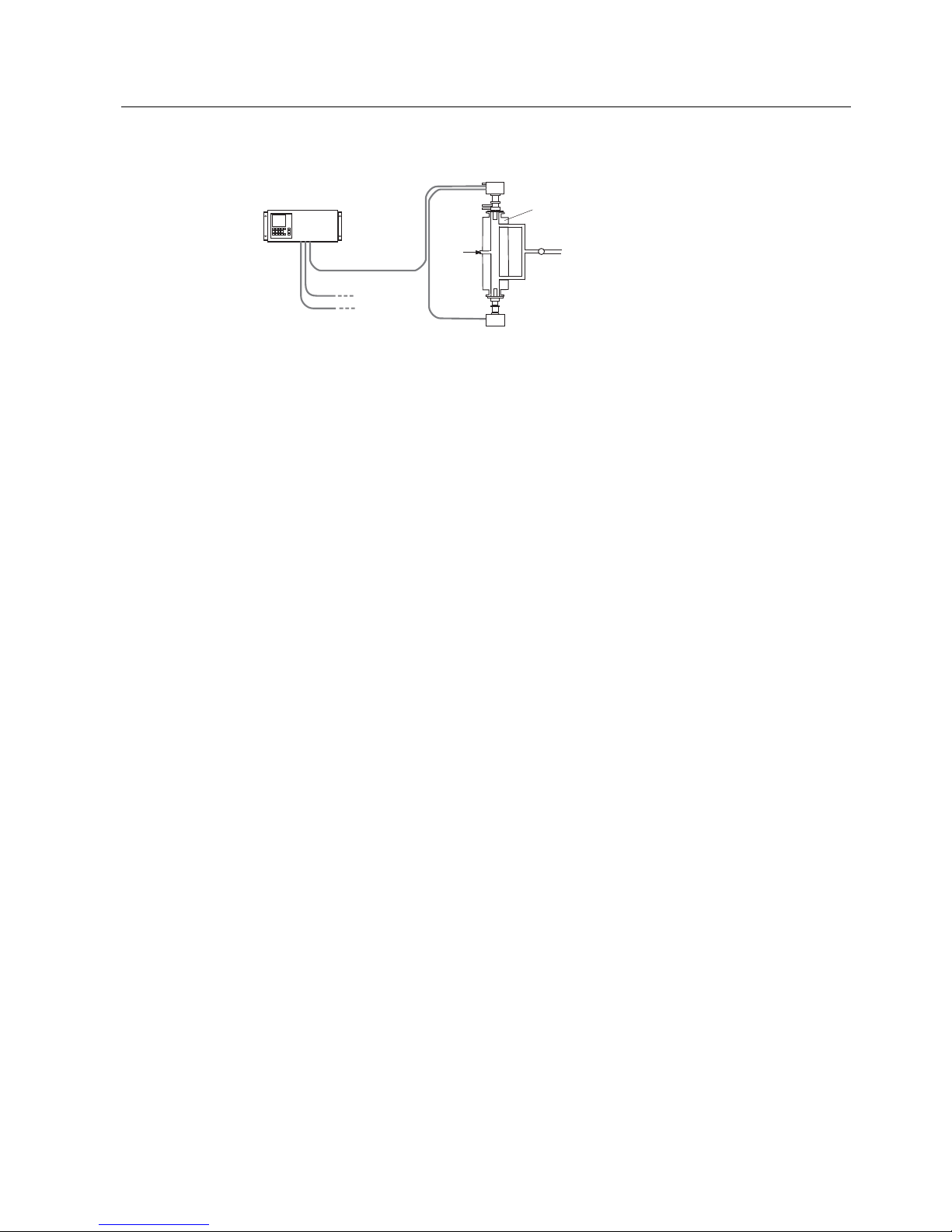
7UDQVPLWWHUXQLW
&HQWUDOXQLW
5HFHLYHU
6DPSOHJDVLQOHW
3XPS
+\EULGFDEOH
PD[OHQJWKP
6XSSOHPHQWDU\
FKDQQHORSWLRQ
6XSSOHPHQWDU\
FKDQQHORSWLRQ
6HQVRUFRQQHFWLQJFDEOH
+HDWLQJ
RSWLRQ
Figure 2-9 Measuring configuration of LDS 6 with heated flow cell
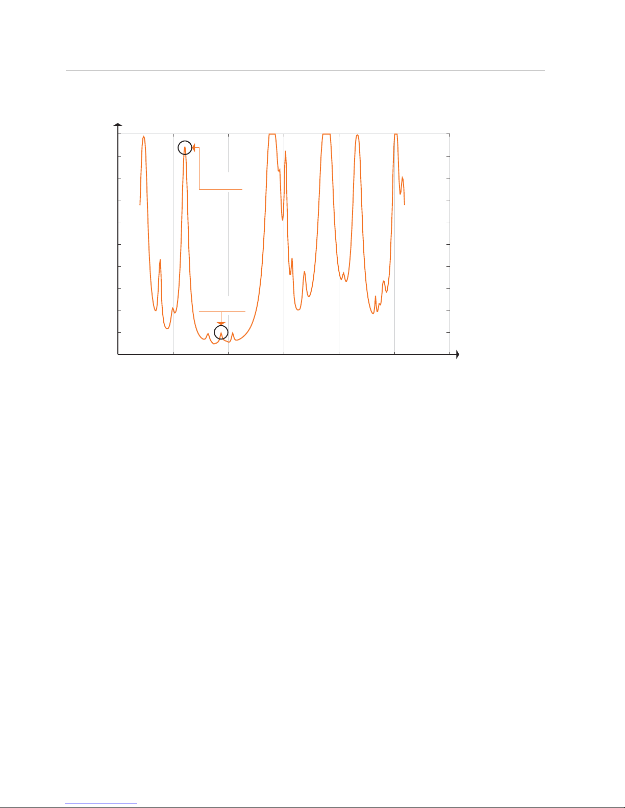
2.5 Measurement Principle
Mode of operation
The operation of LDS 6 is based on the fact that light propagating through a gas mixture will
be absorbed according to Beer-Lambert's law at certain narrow wavelength bands. This is
where the gases possess molecular transitions forming narrow absorption lines.
The light source in LDS 6 is a semi-conductor laser tuned to an appropriate absorption line
for the gas to be measured. The laser light is spectrally much narrower than the gas
absorption line and this, together with a proper choice of absorption line, will result in low
interference from other gases.
The light is modulated, both in frequency and in amplitude, to facilitate detection on the
second harmonic as well as elimination of contribution from spectrally broad absorption
originating from dust, smoke, etc.
LDS 6 is connected to the measuring points by fiber optics. The laser light is guided by a
single-mode fiber from the central unit to the transmitter unit of the in-situ sensor. The sensor
consists of a transmitter and a receiver; the distance between them defines the
measurement path. In the receiver box, the light is focused onto a suitable detector. The
detector signal is then converted into an optical signal and transmitted via a second optical
fiber to the central unit, where the concentration of the gas component is determined from
the detected absorption signal.
LDS 6 usually measures a single gas component by means of the absorption capacity of a
single fully resolved molecular absorption line. The absorption results from conversion of the
radiation energy of the laser light into the internal energy of the molecule. In the working
range of the LDS 6, both rotation-vibration transitions and electronic transitions – such as
with O
2
– can be triggered.
In some specific cases, two components can be measured simultaneously if their absorption
lines are so close to each other that they can be detected within the laser spectrum by one
single scan (for example water (H
2
O) and ammonia (NH3)).
Technical Information
2.5 Measurement Principle
LDS 6
22 Operating Instructions, 01/2009, A5E00295894-05
Relative absorption
Wavelength [μm]
1.543 1.5435 1.544 1.5445 1.545 1.5455 1.546
0.1
0.0
0.2
0.3
0.4
0.5
0.6
0.7
0.8
H2O 15%
NH3 5ppm
1.0
0.9
Figure 2-10 Absorption spectra of water and ammonia
Moreover, in some applications it is possible to determine the gas temperature as a
measured value. In this case, the ratio of the absorbance of two characteristic lines of the
same molecule measured at the same time in the same volume gives the actual temperature
in the process gas.
Typical measurable gases for LDS 6 are:
● Oxygen (O
2
) for low and high pressure
● Oxygen + temperature
● Hydrogen fluoride (HF) + water
● Hydrogen chloride (HCl) + water
● Ammonia (NH
3
) + water
● Water vapor (H
2
O)
● Carbon monoxide (CO)
● Carbon dioxide (CO
2
)
● CO + CO
2
By using an internal reference cell normally filled with the gas measured, the stability of the
spectrometer is permanently checked in a reference channel.
By doing so, the continuous validity of the calibration is ensured without the need to carry out
external recalibration using bottled test gases or reference gas cells.
Technical Information
2.5 Measurement Principle
LDS 6
Operating Instructions, 01/2009, A5E00295894-05
23
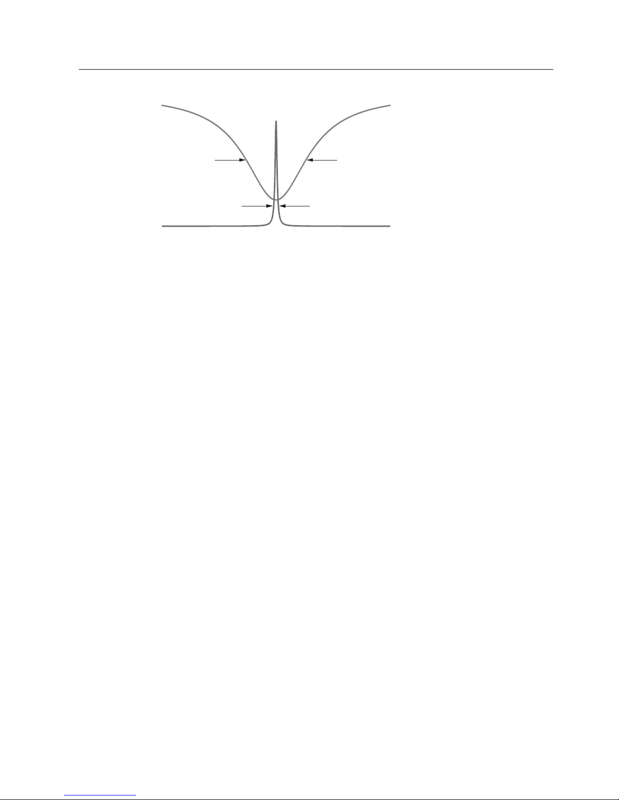
/DVHUOLQH
$EVRUSWLRQOLQH
Figure 2-11 Typical spectral bandwidth of an absorption line compared to the bandwidth of the laser
light
Influences on the measurement
Dust load
As long as the laser beam is able to generate a suitable detector signal, the dust load of the
process gases does not influence the analytical result. By applying a dynamic background
correction, measurements can be carried out without any negative impact. Under good
conditions, particle densities up to 100 g/Nm
3
can be handled by the LDS 6. Varying dust
loads are compensated by scanning the laser over the gas absorption line and the current
background. At a scan position next to the absorption line, the instrument can "see" only
absorption caused by the dust load where at the line center the signal is composed of the
molecular absorption and the continuous, unspecific background absorption. With the
wavelength modulation technique, the actual measured transmission is always compared
with the baseline. After signal processing, phase-sensitive application delivers a signal only
from the molecular line free of background.
The influence of a high dust load is complex and depends on the path length and particle
size. The optical damping increases at longer path lengths. Smaller particles also have a
large influence on the optical damping. With a combination of high dust load, long path
length and small particle size, the technical support at Siemens should be consulted.
Temperature
The temperature influence on the absorption line strength is compensated by a correction
factor determined during calibration. A temperature signal can be fed into the instrument
from an external temperature sensor. This signal is then used to correct the influence of the
temperature on the observed line strength. If the temperature of the sample gas remains
constant, it is alternatively possible to carry out a static correction using a preset value.
At high temperatures there may be noticeable broadband IR radiation of gas and dust, or
flames may occasionally occur in the measurement path. In this case the detector is
protected by an optical bandpass filter to prevent saturation by the strong background
radiation.

Technical Information
2.5 Measurement Principle
LDS 6
24 Operating Instructions, 01/2009, A5E00295894-05
Pressure
The gas pressure can affect the line shape of the molecular absorption line. LDS 6 uses a
special algorithm to adapt the line shape. Additionally, an external pressure signal can be fed
to the instrument to provide complete compensation for the pressure influence including the
density effect.
Cross-interferences
Since LDS 6 derives its signal from a single fully resolved molecular absorption line, crossinterferences with other gases are quite unlikely. LDS 6 is therefore able to measure the
desired gas components very selectively. In special cases, the composition of the process
gas might have an influence on the shape of the absorption line features. This influence is
compensated by analyzing the full shape of the detected signal curve applying specific
algorithms.
Optical path length
The absorption values analyzed by the LDS 6 are typically small. As a result of BeerLambert’s law, the absorption of laser light depends on the optical path length within the gas.
Therefore, the precision in determining the effective optical path length in the process might
limit the overall precision of the measurement.
As the sensor openings toward the process normally need to be purged to keep them clean
over a long period of time, the thickness of the mixing zone between the purging medium
and the process gas and its concentration distribution need to be considered. In a typical insitu installation with some meters of path, the influence of the purging gas on the effective
path length can be neglected.
Path length and dust load are mutually influencing: the higher the dust load in the process,
the shorter the max. possible path length.
Note
Individual requirements for the measuring point can make the utilization of special sensor
equipment necessary. The possibilities for adapting the sensors are:
• Different purging media, such as instrument air, ambient air, nitrogen or steam
• Different purging modes on process and sensor sides
• Special materials of purging tubes and/or sensor flanges
• Cooling or heating of the sensors
• EEx-proof sensor configurations

LDS 6
Operating Instructions, 01/2009, A5E00295894-05
25
Installation Guidelines
3
3.1 Safety Information
It is essential that you observe the given information and warnings!
Electrical Safety
DANGER
Certain parts inside the gas analyzer LDS 6 carry dangerous voltages.
The housing must be closed and grounded before switching on the analyzer.
Death, personal injury and/or damage to persons and/or property may result if this is not
observed.
LDS 6 and CD 6 meet all regulations specified in the present EU regulations
(LVD regulation 2006/95/EC and EMC regulation 2004/108/EC).
The device can be used in an industrial environment.
Laser Safety
All lasers used by LDS 6 are of class 1. The emitted laser light is in most cases invisible
(near infrared) and the intensity is low enough so that the unprotected eye is not damaged
under normal circumstances. LDS 6 has warning labels at appropriate positions according to
DIN EN 60825-1.
CAUTION
This device emits laser beams.
To avoid damage to your eyes never look directly into the laser beam.
If this rule is not followed there is a chance that damage to the unprotected eye may occur
if you look directly into the laser beam particularly when using focusing optics (e. g.
binoculars).
Installation Guidelines
3.1 Safety Information
LDS 6
26 Operating Instructions, 01/2009, A5E00295894-05
Heat Safety
Some metal parts and piping placed near the sensors are at elevated temperatures. The
reason is high temperature purging - either from steam or from air.
CAUTION
The sensors are designed for work at elevated temperatures, particularly when a purging
system is in operation. Even after operation these parts cool off slowly.
For any work around these sensors be sure to wear protective gloves.
If this rule is not followed serious burns of the unprotected skin may happen.
Pressure Safety
The sensor is tested at a pressure of 600 kPa. This pressure value should not be exceeded
in operational conditions.
WARNING
Should pressures higher than 600 kPa occur in the process, this can lead to destruction of
the sensors and their environment. In worst case process media may break free and pollute
the environment.
Avoid under any circumstances process pressures higher than 600 kPa.
If this rule is not followed, death, injuries and/or damage to property and environment can
occur.
Explosion Protection - II 1GD T135 °C EEx ia IIC T4 IP65
The LDS 6, with a central unit and sensors interconnected with optical fibers, is explosion
safe. Only a limited, low energy part of the electronics is located at the measurement site.
The distance between the central unit and the sensors can be several hundred meters. The
LDS 6 system is available in an Ex version and is then delivered with an approval for use in
hazardous environments. The ATEX certificate is a system certificate and is only valid if LDS
6 is installed according to the instructions given in the certificate.

Installation Guidelines
3.1 Safety Information
LDS 6
Operating Instructions, 01/2009, A5E00295894-05
27
Approval
The concept of the Ex approval is that the central unit is unchanged from a standard unit and
that a special Ex sensor pair (CD 6 Ex) is used in the hazardous zone. In addition to this an
explosion protection barrier is added before entry into the hazardous zone. An absolute
condition for the approval is that the equipment is set up according to the drawing, ADM
3040 3050, please refer to the separate ATEX manual for LDS 6.
The protection is as follows:
Cross Duct Sensor -
II 1G Ex ia IIC T4 II 1D IP65 T135 °C.
Central (Barrier) Unit -
II (1)G Ex [ia] IIC II (1)D Ex [iaD].
● Equipment Group: Group II - Surface.
● Equipment Category: Category 1G D - Zone 0. Flammable material can be present
continuously, frequently or for long periods, in gas and dust.
● Type of protection: EEx ia. The equipment present in the hazardous area is intrinsically
safe.
● Explosion group: IIC. This corresponds to a gas group containing Acetylene and
Hydrogen.
● Temperature class: T4. The maximum surface temperature on the equipment is 135 °C
(275 °F) and the ignition temperature of the gas or vapor is between 135 °C (275 °F) and
200 °C (392 °F).
● The sensor housing protection is IP65 and the ambient temperature must be between
-30 °C (-22 °F) and +60 °C (140 °F) .
Liability
Following commissioning, the total responsibility is with the owner.

Installation Guidelines
3.2 General Installation Information
LDS 6
28 Operating Instructions, 01/2009, A5E00295894-05
3.2 General Installation Information
Mounting Conditions
The central unit LDS 6 should be placed on a location which is dust-free and as free as
possible from vibrations. The distance between the central unit and the measurement point,
i.e. the sensor, may not exceed 1000 meters (3,280 ft) for the non ATEX version and
600 m (1,970 ft) for the ATEX version.
During operation the permissible surrounding air temperature is 5 °C (41 °F) to 45 °C
(113 °F), with a relative humidity of maximum 85% non-condensing, around the central unit.
Also ensure that the unit is not exposed to direct solar radiation. If these conditions can’t be
fulfilled the LDS 6 must be installed in a cabinet with controlled environment.
Note
As condensing is normally a problem when moving the device from outside to inside a
building it is recommended that the device should be adapted to room climate for a couple of
hours before starting it.
The back of the unit must be freely accessible. There should be at least 10 cm (4 ") of free
space behind the LDS 6 to accommodate the signal and hybrid cables. To meet the safety
requirements for air convection and cooling there must be a free space of at least 5 cm (2 ")
above and at least 3 cm (1 1/4 ")below LDS 6.
For detailed information on the sensor installation, please refer to the sensor manual
corresponding to your system setup.

Installation Guidelines
3.3 Electrical Connections
LDS 6
Operating Instructions, 01/2009, A5E00295894-05
29
Hybrid Cables
The hybrid cables should be installed such that they are protected from mechanical wear
such as sharp edges or moving parts. During installation always keep the protective tube in
such a position that the single mode fiber connector is protected from dust. The operating
temperature for the cables is -40 to +80°C (-40 to 176 °F) and the installation temperature is
-20 to +80°C (-4 to 176 °F). The bending radius of the cables may never be smaller than
100 mm (4 ").
Note
Throughout the entire installation, keep the fiber ends protected by the protective tubes;
observe that these should only be removed by authorized personnel.
There are three kinds of cables used for the LDS 6 depending on the application:
● Hybrid cables for all types of systems except oxygen. These are installed between the
LDS 6 and the transmitter sensor.
● Hybrid cables for oxygen systems only, also installed between the LDS 6 and the
transmitter sensor.
● Loop cables, same for all systems, are installed between the transmitter sensor and the
receiver sensor.
3.3 Electrical Connections
3.3.1 Power Supply Connections
WARNING
The respective country-specific standards for the installation of power systems with rated
voltages below 1000 V must be followed. Failure to observe these regulations may result in
death, personal injury and/or damage to property.
General
● Check that the local voltage agrees with that specified on the label on the analyzer.
● The cable must be tested according to IEC 60227 or IEC 60245 and must be suitable for
70 °C (158 °F).
● The power cable must be routed separately from the hybrid cables.

Installation Guidelines
3.3 Electrical Connections
LDS 6
30 Operating Instructions, 01/2009, A5E00295894-05
Detachable Cord
● The analyzer is supplied with an appliance plug which may only be connected to the
power supply by qualified personnel. The cross-section of the conductors must be at least
1 mm
2
. The phase conductor must be connected to the identified position (L).
● Only detachable power supply cords tested by an accepted third party Lab accredited for
the region where the unit is to be used is allowed. This cord must be suitable for the rated
current and limited in length. This flexible cord must also be suitable for an ambient
temperature of 70 °C (158 °F) and is not allowed to be mounted in building installations.
● As the kind of appliance inlet is only suitable for 70 °C (158 °F) ambient temperature the
power cord must be kept away with suitable means from surfaces of more than 70 °C
(158 °F) at max. rated operation conditions.
● It is not allowed to install a switch within the power supply cord.
Electrical Protection
● A circuit-breaker shall be part of the installation. It must be provided in the immediate
vicinity of the analyzer (see rating plate for loading capacity). It must also be labeled to
correlate with the instrument.
 Loading...