

Page 1
*9000844135* 9000844135 930702
LD97AA670 Ø Montageanleitung
Ú Installation instructions
Þ Notice de montage
é Installatievoorschrift
Û Instrucciones de montaje
ì Instruções de montagem
â Istruzioni per il montaggio
× Monteringsvejledning
Ý Asennusohje
ê Monteringsveiledning
ó Monteringsanvisning
î Инструкция по монтажу
[
[
[
[
[
Page 2
D
F
F
E
D
E
Page 3
D
E
Page 4
de
Ø
Montageanleitung
: Wichtige Sicherheitshinweise
Diese Anleitung sorgfältig lesen. Nur dann können Sie Ihr Gerät
sicher und richtig bedienen. Die Gebrauchs- und Montageanleitung für einen späteren Gebrauch oder für Nachbesitzer aufbewahren.
Nur bei fachgerechtem Einbau entsprechend der Montageanleitung ist die Sicherheit beim Gebrauch gewährleistet. Der Installateur ist für das einwandfreie Funktionieren am Aufstellungsort
verantwortlich.
Die Breite der Dunstabzugshaube muss mindestens der Breite
der Kochstelle entsprechen.
Für die Installation müssen die aktuell gültigen Bauvorschriften
und die Vorschriften der örtlichen Strom- und Gasversorger
beachtet werden.
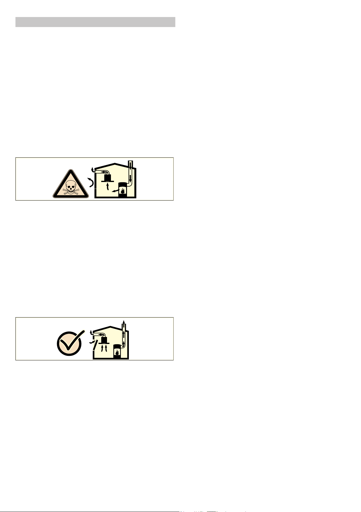
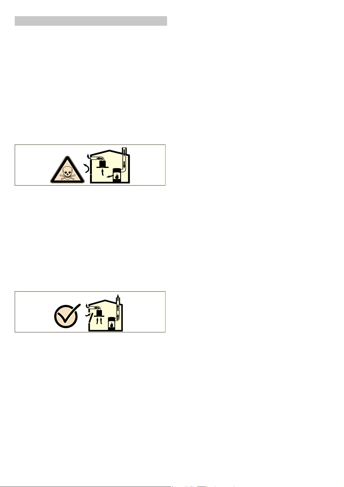
Lebensgefahr!
Zurückgesaugte Verbrennungsgase können zu Vergiftungen
führen.
Immer für ausreichend Zuluft sorgen, wenn das Gerät im Abluftbetrieb gleichzeitig mit einer raumluftabhängigen Feuerstätte
verwendet wird.
Raumluftabhängige Feuerstätten (z. B. gas-, öl-, holz- oder kohlebetriebene Heizgeräte, Durchlauferhitzer, Warmwasserbereiter)
beziehen Verbrennungsluft aus dem Aufstellraum und führen die
Abgase durch eine Abgasanlage (z. B. Kamin) ins Freie.
In Verbindung mit einer eingeschalteten Dunstabzugshaube
wird der Küche und den benachbarten Räumen Raumluft entzogen - ohne ausreichende Zuluft entsteht ein Unterdruck. Giftige
Gase aus dem Kamin oder Abzugsschacht werden in die Wohnräume zurückgesaugt.
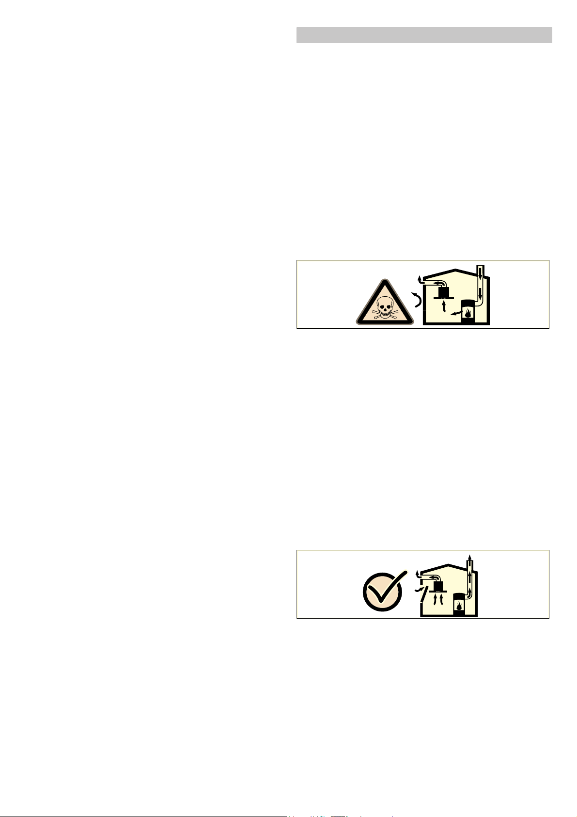
■ Es muss daher immer für ausreichende Zuluft gesorgt wer-
den.
■ Ein Zuluft-/Abluftmauerkasten allein stellt die Einhaltung des
Grenzwertes nicht sicher.
Ein gefahrloser Betrieb ist nur dann möglich, wenn der Unterdruck im Aufstellraum der Feuerstätte 4 Pa (0,04 mbar) nicht
überschreitet. Dies kann erreicht werden, wenn durch nicht verschließbare Öffnungen, z. B. in Türen, Fenstern, in Verbindung
mit einem Zuluft- / Abluftmauerkasten oder durch andere technische Maßnahmen, die zur Verbrennung benötigte Luft nachströmen kann.
Ziehen Sie in jedem Fall den Rat des zuständigen Schornsteinfegermeisters hinzu, der den gesamten Lüftungsverbund des
Hauses beurteilen kann und Ihnen die passende Maßnahme zur
Belüftung vorschlägt.
Wird die Dunstabzugshaube ausschließlich im Umluftbetrieb eingesetzt, ist der Betrieb ohne Einschränkung möglich.
Lebensgefahr!
Zurückgesaugte Verbrennungsgase können zu Vergiftungen
führen. Bei Installation einer Lüftung mit einer kamingebundenen
Feuerstelle muss die Stromzuführung der Haube mit einer
geeigneten Sicherheitsschaltung versehen werden.
Brandgefahr!
■ Bei gleichzeitigem Betrieb mehrerer Gas-Kochstellen entwi-
ckelt sich große Hitze. Das Lüftungsgerät kann beschädigt
oder in Brand gesetzt werden. Das Lüftungsgerät darf nur mit
Gas-Kochstellen kombiniert werden, die eine maximale
Gesamtleistung von 12,4 kW nicht überschreiten.
Brandgefahr!
■ Die Fettablagerungen im Fettfilter können sich entzünden. Die
vorgegebenen Sicherheitsabstände müssen eingehalten werden, um einen Hitzestau zu vermeiden. Beachten Sie die
Angaben zu Ihrem Kochgerät. Werden Gas- und Elektro-Kochstellen zusammen betrieben, gilt der größte angegebene
Abstand.
Das Gerät darf nur an einer Seite direkt neben einem Hochschrank oder einer Wand installiert werden. Der Abstand zur
Wand oder zum Hochschrank muss mind. 50 mm betragen.
Verletzungsgefahr!
■ Bauteile innerhalb des Gerätes können scharfkantig sein.
Schutzhandschuhe tragen.
Verletzungsgefahr!
■ Das Gerät ist schwer. Zum Bewegen des Gerätes sind
2 Personen erforderlich. Nur geeignete Hilfsmittel verwenden.
Stromschlaggefahr!
Bauteile innerhalb des Gerätes können scharfkantig sein. Das
Anschlusskabel kann beschädigt werden. Anschlusskabel während der Installation nicht knicken oder einklemmen.
Erstickungsgefahr!
Verpackungsmaterial ist für Kinder gefährlich. Kinder nie mit
Verpackungsmaterial spielen lassen.
Kippgefahr!
Das Gerät ist sehr schmal und kann leicht umkippen. Gerät
nicht aufrecht auf den Boden stellen. Gerät flach auf den Boden
legen.
Allgemeine Hinweise
Abluftbetrieb
Hinweis: Die Abluft darf weder in einen in Betrieb befindlichen
Rauch- oder Abgaskamin, noch in einen Schacht, welcher der
Entlüftung von Aufstellungsräumen von Feuerstätten dient,
abgegeben werden.
■ Soll die Abluft in einen Rauch- oder Abgaskamin geführt wer-
den, der nicht in Betrieb ist, muss die Zustimmung des zuständigen Schornsteinfegermeisters eingeholt werden.
■ Wird die Abluft durch die Außenwand geleitet, sollte ein Teles-
kop-Mauerkasten verwendet werden.
Abluftleitung
Hinweis: Für Beanstandungen, die auf die Rohrstrecke zurück-
zuführen sind, übernimmt der Hersteller des Gerätes keine
Gewährleistung.
■ Das Gerät erreicht seine optimale Leistung durch ein kurzes,
geradliniges Abluftrohr und einen möglichst großen Rohrdurchmesser.
■ Durch lange raue Abluftrohre, viele Rohrbögen oder Rohr-
durchmesser, die kleiner als 150 mm sind, wird die optimale
Absaugleistung nicht erreicht und das Lüftergeräusch wird
lauter.
■ Die Rohre oder Schläuche zum Verlegen der Abluftleitung
müssen aus nicht brennbarem Material sein.
Rundrohre
Es wird ein Innendurchmesser von 150 mm empfohlen, jedoch
mindestens 120 mm.
Flachkanäle
Der Innenquerschnitt muss dem Durchmesser der Rundrohre
entsprechen.
Ø 150 mm ca. 177 cm
Ø 120 mm ca. 113 cm
■ Flachkanäle sollten keine scharfen Umlenkungen haben.
■ Bei abweichenden Rohrdurchmessern Dichtstreifen einsetzen.
Gas-Kochfeld
Das Gerät kann in Verbindung mit einem Gas-Kochfeld verwendet werden.
Achtung!
Das Gas-Kochfeld darf folgende Werte nicht überschreiten:
■ Maximalleistung gesamt: 12,4 kW
■ Maximalleistung Einzelbrenner: 5 kW
■ maximal 5 Einzelbrenner
2
2
Page 5

Elektrischer Anschluss
: Stromschlaggefahr!
Bauteile innerhalb des Gerätes können scharfkantig sein. Das
Anschlusskabel kann beschädigt werden. Anschlusskabel während der Installation nicht knicken oder einklemmen.
Vor Geräteanschluss Hausinstallation überprüfen. Auf geeignete
Absicherung der Hausinstallation achten. Spannung und Frequenz des Gerätes müssen mit der elektrischen Installation
übereinstimmen (siehe Typenschild).
Das Gerät entspricht der Schutzklasse I und darf nur mit Schutzleiter-Anschluss betrieben werden.
In der Installation muss ein allpoliger Trennschalter mit mindestens 3-mm-Kontaktöffnung vorhanden sein. Dieser muss nach
dem Einbau noch zugänglich sein.
Das Verlegen oder der Austausch der Anschlussleitung darf nur
vom Elektrofachmann unter Berücksichtigung der einschlägigen
Vorschriften ausgeführt werden.
Wenn die Netzanschlussleitung dieses Gerätes beschädigt wird,
muss sie durch eine spezielle Anschlussleitung ersetzt werden,
die beim Hersteller oder seinem Kundendienst erhältlich ist.
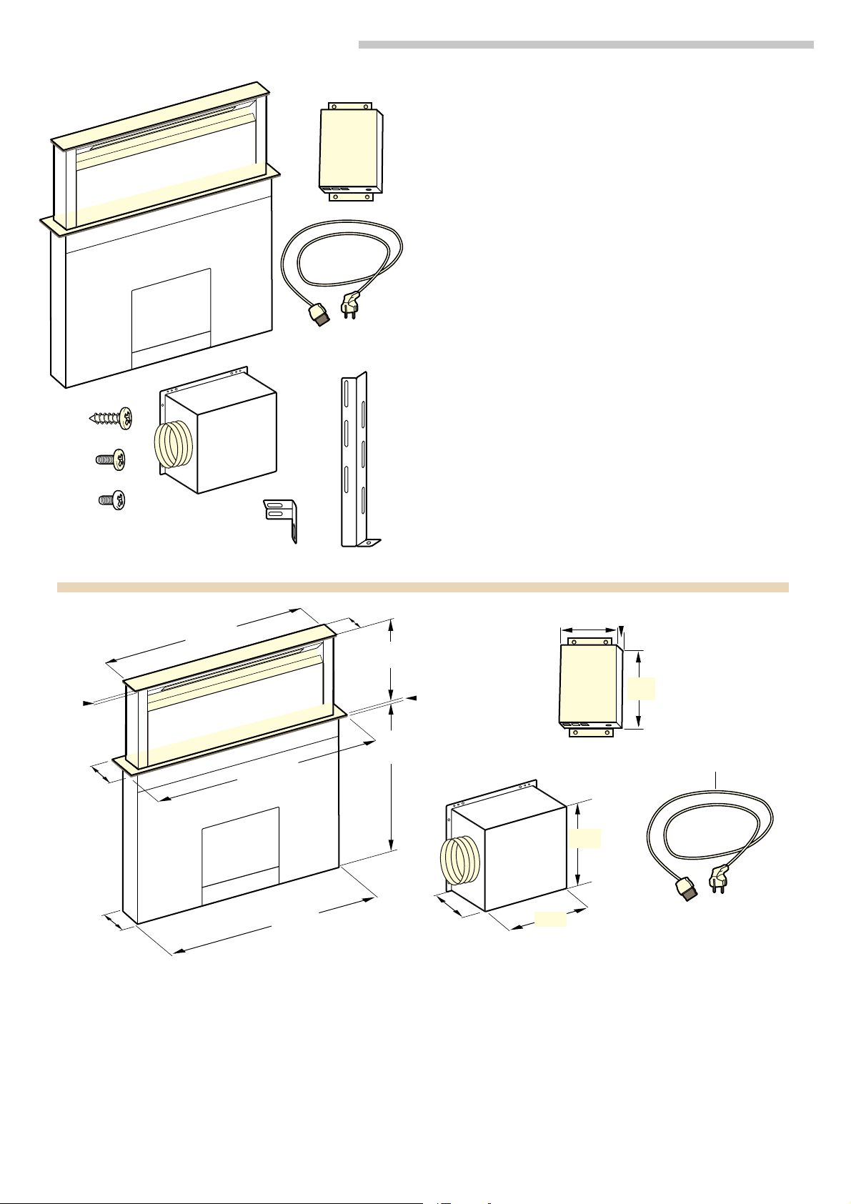
Gerätemaße (Bild 1)
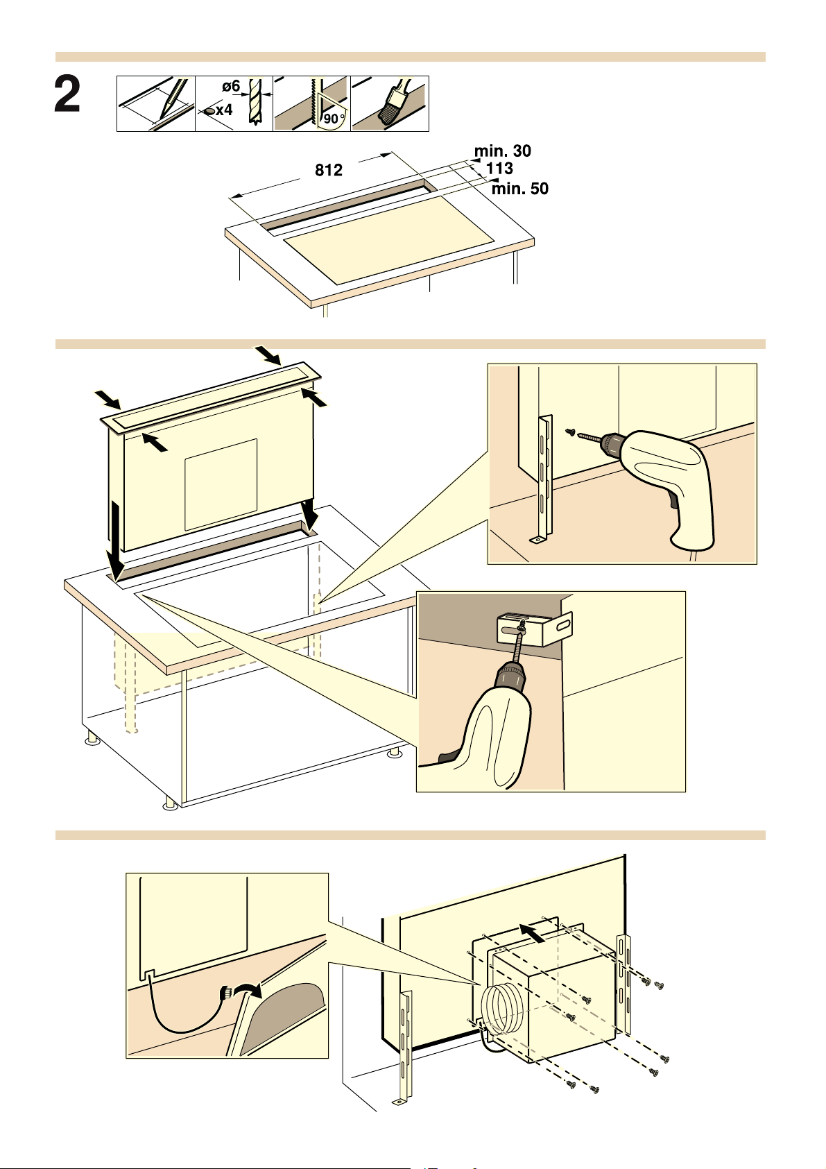
Möbel vorbereiten (Bild 2)
Das Einbaumöbel muss bis 90°C temperaturbeständig sein. Die
Stabilität des Einbaumöbels muss auch nach den Ausschnittarbeiten gewährleistet sein.
Den Ausschnitt gemäß der Einbauskizze herstellen. Der Winkel
der Schnittfläche zur Arbeitsplatte muss 90° betragen.
Nach Ausschnittarbeiten Späne entfernen. Schnittflächen hitzebeständig versiegeln.
Mindestabstand der Geräteunterseite zu Möbelteilen von 10 mm
beachten.
Die Arbeitsplatte muss verstärkt werden, wenn der Steg zwischen dem Gerät und der Wand weniger als 30 mm oder der
Steg zwischen dem Gerät und des Kochfelds weniger als als 50
mm beträgt. Ansonsten ist keine ausreichende Stabilität gegeben. Das verwendete Verstärkungsmaterial muss hitze- und
feuchtigkeitsbeständig sein.
Hinweise
■ Die Arbeitsplatte, in die das Gerät eingebaut wird, muss über
eine Tragfähigkeit von etwa 60 kg verfügen.
■ Die Ebenheit des Gerätes erst nach Installation in der Einbau-
öffnung überprüfen.
Gerät einbauen
1. Gerät von oben in den Ausschnitt der Arbeitsplatte
schieben. (Bild 3a).
2. Gerät gleichmäßig in den Ausschnitt einsetzen. Von oben fest
in den Ausschnitt drücken.
Hinweise
■ Das Gerät muss fest im Ausschnitt sitzen und darf sich nicht
verschieben (z. B. bei der Reinigung). Bei Ausschnittsbreite
an der oberen Toleranzgrenze wenn nötig Leisten seitlich im
Ausschnitt befestigen.
■ Die beiden Kunststoffteile links und rechts an der Abde-
ckung entfernen (Bild 3a).
3. Gerät im Schrank ausrichten. Darauf achten, dass der Rahmen
des Gerätes plan auf der Arbeitsplatte aufliegt. Die Befestigungswinkel am Gerät und am Möbelboden befestigen
(Bild 3b).
4. Obere Befestigungswinkel befestigen. Am Gerät sind Bohrun-
gen zur Befestigung der Winkel vorgesehen. Die Befestigungswinkel oben am Gerät und an der Unterseite der Arbeitsplatte
befestigen (Bild 3c).
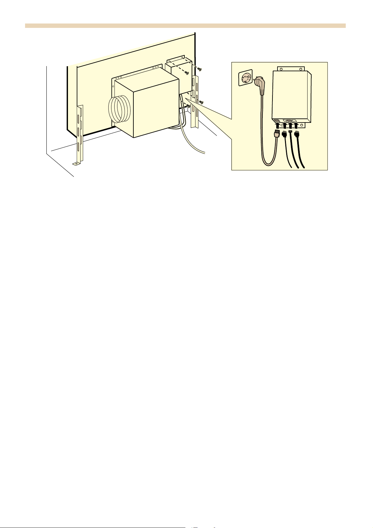
5. Kabel für den Lüftermotor mit dem Lüfter verbinden. Die Buch-
se befindet sich an der Stirnseite des Lüfters nahe dem Gehäuseboden. (Bild 4a).
6. Lüftergehäuse über die Aussparung an das Gerät schrau-
ben. (Bild 4b).
Hinweis: Das Lüftergehäuse kann alternativ an der Rückseite
des Gerätes montiert werden.
Hierzu die Abdeckklappe auf der Rückseite des Gerätes ab-
schrauben und an die Vorderseite des Gerätes montieren.
Das Kabel des Lüfermotors muss dabei ebenfalls durch die
Rückseite des Gerätes geführt werden.
7. Steuereinheit neben dem Lüftergehäuse am Gerät
befestigen (Bild 5a).
Die Steuereinheit kann alternativ an der anderen Seite des Lüf-
termotors und an der Möbelwand befestigt werden.
Achtung!
Eindringende Feuchtigkeit kann einen Stromschlag verursachen. Steuereinheit nicht am Boden des Einbaumöbels befestigen.
8. Verbindungskabel anschließen (Bild 5b). Die Steuerkabel von
der Steuereinheit zum Gerät fest einstecken. Die Stecker müssen einrasten. Steuereinheit an das Netz anschließen und
Funktion prüfen. Falls das Gerät nicht funktioniert: Den korrekten Sitz der Verbindungskabel prüfen!
Gerät ausbauen
1. Gerät stromlos machen.
2. Verschraubungen mit dem Möbel lösen.
3. Anbauteile des Gerätes abschrauben.
4. Gerät von unten herausdrücken.
Achtung!
Geräteschaden! Gerät nicht von oben heraushebeln.
Page 6
en
Ú
Installation instructions
: Important safety information
Read these instructions carefully. Only then will you be able to
operate your appliance safely and correctly. Retain the
instruction manual and installation instructions for future use or
for subsequent owners.
The appliance can only be used safely if it is correctly installed
according to the safety instructions. The installer is responsible
for ensuring that the appliance works perfectly at its installation
location.
The width of the extractor hood must correspond at least with
the width of the hob.
For the installation, observe the currently valid building
regulations and the regulations of the local electricity and gas
suppliers.
Danger of death!
Risk of poisoning from flue gases that are drawn back in.
Always ensure adequate fresh air in the room if the appliance is
being operated in exhaust air mode at the same time as room
air-dependent heat-producing appliance is being operated.
Room air-dependent heat-producing appliances (e.g. gas, oil,
wood or coal-operated heaters, continuous flow heaters or water
heaters) obtain combustion air from the room in which they are
installed and discharge the exhaust gases into the open air
through an exhaust gas system (e.g. a chimney).
In combination with an activated vapour extractor hood, room air
is extracted from the kitchen and neighbouring rooms - a partial
vacuum is produced if not enough fresh air is supplied. Toxic
gases from the chimney or the extraction shaft are sucked back
into the living space.
■ Adequate incoming air must therefore always be ensured.
■ An incoming/exhaust air wall box alone will not ensure
compliance with the limit.
Safe operation is possible only when the partial vacuum in the
place where the heat-producing appliance is installed does not
exceed 4 Pa (0.04 mbar). This can be achieved when the air
needed for combustion is able to enter through openings that
cannot be sealed, for example in doors, windows, incoming/
exhaust air wall boxes or by other technical means.
In any case, consult your responsible Master Chimney Sweep.
He is able to assess the house's entire ventilation setup and will
suggest the suitable ventilation measures to you.
Unrestricted operation is possible if the vapour extractor hood is
operated exclusively in the circulating-air mode.
Danger of death!
Risk of poisoning from flue gases that are drawn back in. If
installing a ventilation system in a room with a heat-producing
appliance connected to a chimney/flue, the electricity supply to
the hood must be equipped with a suitable safety switch.
Risk of fire!
■ Operating several gas burners at the same time gives rise to a
great deal of heat. The ventilation appliance may become
damaged or catch fire. The ventilation appliance must only be
combined with gas burners that do not exceed the maximum
total output of 12.4 kW.
Risk of fire!
■ Grease deposits in the grease filter may catch fire. The
specified safety distances must be observed in order to
prevent an accumulation of heat. Observe the specifications
for your cooking appliance. If gas and electric hobs are
operated together, the largest specified distance applies.
Only one side of the appliance may be installed directly next
to a high-sided unit or a wall. The distance between the
appliance and wall or high-sided unit must be at least 50 mm.
Risk of injury!
■ Components inside the appliance may have sharp edges.
Wear protective gloves.
Risk of injury!
■ The appliance is heavy. To move the appliance, 2 people are
required. Use only suitable tools and equipment.
Risk of electric shock!
Components inside the appliance may have sharp edges. These
may damage the connecting cable. Do not kink or pinch the
connecting cable during installation.
Danger of suffocation!
Packaging material is dangerous to children. Never allow
children to play with packaging material.
Risk of tipping!
The appliance is very narrow and can tip over easily. Do not set
the appliance on an uneven surface. Set the appliance flat on
the surface.
General information
Exhaust air mode
Note: The exhaust air must not be conveyed into a functioning
smoke or exhaust gas flue or into a shaft which is used to
ventilate installation rooms which contain heat-producing
appliances.
■ Before conveying the exhaust air into a non-functioning smoke
or exhaust gas flue, obtain the consent of the heating
engineer responsible.
■ If the exhaust air is conveyed through the outer wall, a
telescopic wall box should be used.
Exhaust duct
Note: The appliance manufacturer does not assume any
warranty for complaints attributable to the pipe section.
■ The appliance achieves its optimum performance by means of
a short, straight exhaust air pipe and as large a pipe diameter
as possible.
■ Because of long rough exhaust air pipes, many of which are
pipe bends or have diameters smaller than 150 mm, the
optimum extraction performance is not achieved and fan
noise is increased.
■ The pipes or hoses for laying the exhaust duct must consist of
non-combustible material.
Round pipes
An inner diameter of 150 mm, but at least 120 mm, is
recommended.
Flat ducts
The inner cross-section must correspond to the diameter of the
round pipes.
Ø 150 mm approx. 177 cm
Ø 120 mm approx. 113 cm
■ Flat ducts should have no sharp deflections.
■ Use sealing strip for deviating pipe diameters.
Gas hob
The appliance can be used in conjunction with a gas hob.
Caution!
The gas hob must not exceed the following values:
■ Total maximum output: 12.4 kW
■ Maximum output for a single burner: 5 kW
■ Maximum of 5 single burners
Electrical connection
: Risk of electric shock!
Components inside the appliance may have sharp edges. These
may damage the connecting cable. Do not kink or pinch the
connecting cable during installation.
Check the indoor installation before connecting the appliance.
Ensure that the indoor installation is sufficiently fused. The
voltage and frequency of the appliance must correspond to that
of the electrical installation (see rating plate).
The appliance corresponds to protection class I and must only
be operated with a protective earth connection.
An all-pole isolating switch with at least a 3 mm contact gap
must be fitted in the installation. The plug must still be
accessible after installation.
Only a qualified electrician who takes the appropriate
regulations into account may install or replace the connecting
cable.
2
2
Page 7
If the power cord for the appliance becomes damaged, this
must be replaced with a special connecting cable that can be
obtained from the manufacturer or the manufacturer's customer
service department.
Appliance measurements (fig. 1)
Preparing the kitchen units (fig. 2)
The fitted unit must be heat-resistant up to 90 °C. The stability of
the fitted unit must also be guaranteed after the cut-out work.
Make the cut-out in accordance with the installation drawing.
The cut surface must be at a 90° angle to the work surface.
After making the cut-outs, remove any shavings. Seal any cut
surfaces to make them heat-resistant.
Ensure that there is a minimum clearance of at least 10 mm
from the underside of the appliance to the unit parts.
The work surface must be reinforced if the gap between the
appliance and the wall is less than 30 mm, or the gap between
the appliance and the hob is less than 50 mm. Otherwise there
is not enough stability. The reinforcing material used must be
heat and moisture resistant.
Notes
■ The work surface in which the appliance is installed must have
a load-bearing capacity of approximately 60 kg.
■ Only check the evenness of the appliance after fitting it in the
installation opening.
Fitting the appliance
1. Slide the appliance into the cut-out of the work surface from
above. (Fig. 3a).
2. Insert the appliance evenly in the cut-out. From above, push it
down firmly into the cut-out.
Notes
■ The appliance must be seated securely in the cut-out and
must not move (e.g. during cleaning). If the width of the cutout is at the upper end of the tolerance range, secure
battens to the sides of the cut-out, if required.
■ Remove both of the plastic parts from the left and right of
the cover (picture 3a).
3. Level the appliance in the cupboard. Ensure that the frame for
the appliance plan lays flat on the work surface. Secure the
mounting bracket to the appliance and the base of the
unit (fig. 3b).
4. Secure the upper mounting bracket. Holes are provided on the
appliance for securing the angle bracket in place. Secure the
mounting bracket to the top of the appliance and the underside
of the work surface (fig. 3c).
5. Connect the fan motor cable with the fan. The socket can be
found on the front side of the fan near the base of the
housing. (fig. 4a).
6. Screw the fan housing to the appliance above the opening.
(fig. 4b).
Note: The fan housing can alternatively be fitted to the rear of
the appliance.
To do this, unscrew the cover panel on the rear of the
appliance and fit it to the front of the appliance.
The fan motor cable must also be routed through the rear of
the appliance.
7. Secure the control unit to the appliance next to the fan
housing (fig. 5a).
Alternatively, the control unit can be secured on the other side
of the fan motor on the unit wall.
Caution!
Penetrating moisture may result in an electric shock. Do not
secure the control unit to the base of the fitted unit.
8. Connect the connecting cable (fig. 5b). Firmly insert the control
cable from the control unit into the appliance. The plug must
snap into place. Connect the control unit to the mains and
check that it works correctly. If the appliance does not work:
Check that the connection cable is positioned correctly.
Removing the appliance
1. Disconnect the appliance from the power supply.
2. Loosen the screw connections with the unit.
3. Unscrew the attachment parts of the appliance.
4. Push out the appliance from below.
Caution!
Danger to the appliance. Do not lift up the appliance from
above.
fr
Þ
Notice de montage
: Précautions de sécurité importantes
Lire attentivement ce manuel. Ce n'est qu'alors que vous
pourrez utiliser votre appareil correctement et en toute sécurité.
Conserver la notice d'utilisation et de montage pour un usage
ultérieur ou pour le propriétaire suivant.
La sécurité de l’appareil à l’usage est garantie s’il a été encastré
conformément à la notice de montage. Le monteur est
responsable du fonctionnement correct sur le lieu où l'appareil
est installé.
La largeur de la hotte aspirante doit équivaloir à celle de la table
de cuisson.
L’installation doit avoir lieu en respectant les prescriptions
actuellement en vigueur dans le bâtiment, ainsi que les
prescriptions publiées par les compagnies distributrices
d’électricité et de gaz.
Danger de mort !
Il y a risque d'intoxication par réaspiration des gaz de
combustion.
En cas d'utilisation simultanée de l'appareil en mode évacuation
de l'air et d'un foyer à combustion alimenté en air ambiant,
veillez impérativement à ce que l'apport d'air soit suffisant.
Les foyers à combustion alimentés en air ambiant (par exemple
appareils de chauffage, au gaz, au bois, au fioul ou au charbon,
les chauffe-eau, chauffe-eau accumulateurs) prélèvent l'air de
combustion dans la pièce où ils sont installés et rejettent les gaz
de fumée à l'extérieur par le biais d'un système spécifique
(cheminée par exemple).
Lorsque la hotte aspirante est en marche, elle prélève de l'air
dans la cuisine et dans les pièces voisines ; si l'apport d'air frais
est trop faible, une dépression se forme. Des gaz toxiques
provenant de la cheminée ou du conduit d'évacuation sont
réaspirés dans les pièces d'habitation.
■ Il faut donc toujours s'assurer que l'apport d'air frais est
suffisant
■ La présence d'une ventouse télescopique d'apport et
d'évacuation d'air ne suffit pas à assurer le respect de la
valeur limite.
Le fonctionnement sûr de l'appareil n'est possible que si la
dépression dans la pièce où est installé le foyer ne dépasse pas
4 Pa (0,04 mbar). On y parvient en présence d'ouvertures non
obturables ménagées par ex. dans les portes, fenêtres et en
association avec des ventouses télescopiques d'admission/
évacuation de l'air à travers la maçonnerie ou par d'autres
mesures techniques permettant à l'air d'affluer pour assurer la
combustion.
Demandez toujours conseil au maître ramoneur compétent qui
pourra évaluer l'ensemble du réseau de ventilation de la maison
et vous proposer le moyen le mieux adapté pour l'aération.
Si la hotte aspirante est utilisée exclusivement en mode
recyclage, le fonctionnement est possible sans restrictions.
Danger de mort !
Il y a risque d'intoxication par réaspiration des gaz de
combustion. Lors de l'installation d'une ventilation avec un foyer
relié à une cheminée, l'alimentation électrique de la hotte doit
être munie d'un circuit de sécurité approprié.
Page 8

Risque d'incendie !
■ Lors du fonctionnement simultané de plusieurs foyers gaz il y
a une forte production de chaleur. La hotte peut être
endommagée ou prendre feu. La hotte doit uniquement être
combinée avec des foyers gaz qui ne dépassent pas une
puissance totale maximale de 12,4 kW.
Risque d'incendie !
■ Les dépôts de graisse dans le filtre à graisse peuvent
s'enflammer. Les distances de sécurité indiquées doivent être
respectées, afin d'éviter une accumulation de chaleur. Veuillez
respecter les indications relatives à votre appareil de cuisson.
Si votre table de cuisson combine des foyers gaz et
électrique, l'écart maximal s’applique.
Il est permis de monter l'appareil avec un seul coté
directement à côté d'un meuble haut ou près d'un mur haut.
La distance vers la paroi ou le meuble haut doit être d'au
moins 50 mm.
Risque de blessure !
■ Des pièces à l'intérieur de l'appareil peuvent présenter des
arêtes vives. Porter des gants de protection.
Risque de blessure !
■ L'appareil est lourd. 2 personnes sont nécessaires pour
déplacer l'appareil. Utiliser exclusivement des moyens
appropriés.
Risque de choc électrique !
Des pièces à l'intérieur de l'appareil peuvent présenter des
arêtes vives. Il y a risque d'endommagement du câble
d'alimentation. Pendant l’installation, veiller à ne pas plier ni
coincer le câble d’alimentation.
Risque d'asphyxie !
Le matériel d'emballage est dangereux pour les enfants. Ne
permettez jamais aux enfants de jouer avec les matériaux
d’emballage.
Risque de basculement !
Cet appareil est très étroit et peut facilement basculer. Ne pas
déposer l'appareil debout sur le sol. Poser l'appareil à plat sur le
sol.
Consignes générales
Mode Évacuation de l’air
Remarque : L’air sortant ne doit pénétrer ni dans une cheminée
en service destinée à évacuer la fumée ou des gaz brûlés, ni
dans une gaine servant à aérer les locaux où sont installés des
foyers à combustion.
■ Si l’air sortant circule par une cheminée non en service
destinée à évacuer la fumée ou des gaz brûlés, il faudra vous
procurer l’accord du ramoneur compétent dans votre quartier.
■ Si l’air sortant traverse la paroi extérieure, il faudrait utiliser
une ventouse télescopique.
Conduit d'évacuation
Remarque : Le fabricant de l'appareil décline toute garantie
pour les problèmes de fonctionnement liés à la tuyauterie.
■ L'appareil atteint un rendement d'autant meilleur que le tuyau
d'évacuation est court et droit et que son diamètre est grand.
■ Si les tuyaux d'évacuation sont longs, présentent de
nombreux coudes ou ont un diamètre inférieur à 150 mm, la
puissance maximale d'aspiration ne sera pas atteinte et le
ventilateur fera plus de bruit.
■ Les tuyaux rigides ou souples constituant le conduit
d'évacuation doivent être fabriqués dans un matériau non
inflammable.
Conduits de section ronde
Nous recommandons un diamètre intérieur de 150 mm, mais
d'au moins 120 mm.
Conduits plats
La section intérieure doit être équivalente au diamètre des
conduits ronds.
Ø 150 mm environ 177 cm
Ø 120 mm environ 113 cm
■ Les conduits plats ne doivent pas présenter aucun coude
prononcé.
■ Si des tuyaux de plusieurs diamètres sont utilisés, il faut
prévoir du ruban adhésif à étancher.
2
2
Table de cuisson gaz
L'appareil peut être utilisé associé à une table de cuisson gaz.
Attention !
La table de cuisson gaz ne doit pas dépasser les valeurs
suivantes :
■ Puissance totale maximale : 12,4 kW
■ Puissance maximale brûleur individuel : 5 kW
■ Au maximum 5 brûleurs individuels
Branchement électrique
: Risque de choc électrique !
Des pièces à l'intérieur de l'appareil peuvent présenter des
arêtes vives. Il y a risque d'endommagement du câble
d'alimentation. Pendant l’installation, veiller à ne pas plier ni
coincer le câble d’alimentation.
Avant de raccorder l'appareil, vérifier l'installation domestique.
Veiller à ce que la protection de l'installation domestique soit
appropriée. La tension et la fréquence de l'appareil doivent
correspondre à l'installation électrique (voir la plaque
signalétique).
L'appareil répond à la classe de protection I et doit uniquement
être utilisé avec une prise de terre.
Un sectionneur omnipolaire avec un interstice d'ouverture de
contact d'au moins 3 mm doit être présent dans l'installation.
Celui-ci doit encore être accessible après l'encastrement.
Seul un électricien agréé est habilité à installer ou à remplacer
le cordon de raccordement, en respectant les prescriptions en
vigueur.
Si le câble de raccordement secteur de cet appareil est
endommagé il doit être remplacé par un câble de raccordement
spécial qui est en vente auprès du fabricant ou de son service
après-vente.
Cotes de l'appareil (fig. 1)
Préparation du meuble (fig. 2)
Le meuble d'encastrement doit résister à des températures
jusqu'à 90°C. La stabilité du meuble d'encastrement doit aussi
être garantie après les travaux de découpe.
Confectionner la découple conformément au croquis
d'installation. L'angle du chant de la découpe par rapport au
plan de travail doit être de 90°.
Enlever les copeaux après les travaux de découpe. Sceller les
chants de la découpe de façon thermostable.
Respecter une distance minimale de 10 mm entre le dessous
de l'appareil et les éléments du meuble.
Le plan de travail doit être renforcé si l'âme entre l'appareil et le
mur est inférieure à 30 mm ou si l'âme entre l'appareil et la table
de cuisson est inférieure à 50 mm. Sinon une stabilité suffisante
n'est pas garantie. Le matériau de renforcement utilisé doit être
résistant à la chaleur et à l'humidité.
Remarques
■ Le plan de travail dans lequel l'appareil est encastré doit avoir
une capacité de charge d'env. 60 kg.
■ Vérifier la planéité de l'appareil seulement après l'installation
dans l'ouverture d'encastrement.
Page 9

Pose de l'appareil
1. Glisser l'appareil par le haut dans la découpe du plan de
travail. (Fig. 3a).
2. Introduire l'appareil uniformément dans la découpe. L'appuyer
fermement d'en haut dans la découpe.
Remarques
■ L'appareil doit se trouver correctement dans la découpe et
ne doit pas se décaler (par ex. lors du nettoyage). Si la
largeur de la découpe se situe à la limite de tolérance
supérieure, fixer si nécessaire des baguettes sur le côté
dans la découpe.
■ Enlever les deux pièces en plastique à gauche et à droite
du recouvrement (fig. 3a).
3. Aligner l'appareil dans le meuble. Veiller à ce que le cadre de
l'appareil repose à plat sur le plan de travail. Fixer les équerres
sur l'appareil et sur le fond du meuble (fig. 3b).
4. Fixer les équerres de fixation supérieures. L'appareil possède
des perçages pour fixer les équerres. Fixer les équerres en
haut de l'appareil et sur le dessous du plan de travail (fig. 3c).
5. Relier le câble pour le moteur du ventilateur au ventilateur. La
prise se trouve sur le côté frontal du ventilateur, près du fond
du corps. (Fig. 4a).
6. Visser le corps du ventilateur sur l'appareil par l'évidement.
(Fig. 4b).
Remarque : Le corps du ventilateur peut aussi être monté sur
la face arrière de l'appareil.
Pour cela, dévisser le volet de recouvrement à l'arrière de
l'appareil et le monter sur le devant de l'appareil.
Le câble du moteur du ventilateur doit alors également être
passé par l'arrière de l'appareil.
7. Fixer l'unité de commande sur l'appareil à côté du corps du
ventilateur (fig. 5a).
L'unité de commande peut aussi être fixée de l'autre côté du
moteur du ventilateur et sur la paroi du meuble.
Attention !
De l'humidité qui pénètre peut occasionner un choc électrique.
Ne pas fixer l'unité de commande au fond du meuble
d'encastrement.
8. Brancher les câbles de raccordement (fig. 5b). Connecter
fermement les câbles de commande de l'unité de commande
vers l'appareil. Les fiches doivent s'encliqueter. Connecter
l'unité de commande au secteur et contrôler le fonctionnement.
Si l'appareil ne fonctionne pas : Vérifier la fixation correcte des
câbles de raccordement !
Dépose de l'appareil
1. Mettre l'appareil hors tension.
2. Desserrer les vissages au meuble.
3. Dévisser les pièces de montage de l'appareil.
4. Faire sortir l'appareil en le poussant par le bas.
Attention !
Risque de détérioration de l'appareil ! Ne pas extraire l'appareil
par le haut en faisant levier.
nl
é
Installatievoorschrift
: Belangrijke veiligheidsvoorschriften
Lees deze gebruiksaanwijzing zorgvuldig door. Alleen dan kunt
u uw apparaat goed en veilig bedienen. Bewaar de
gebruiksaanwijzing voor later gebruik of om door te geven aan
een volgende eigenaar.
De veiligheid is alleen gewaarborgd bij een deskundige
montage volgens de montagehandleiding. De installateur is
verantwoordelijk voor een goede werking op de plaats van
opstelling.
De breedte van de afzuigkap moet minstens overeenkomen met
de breedte van het kooktoestel.
Bij de installatie moeten de actuele geldige bouwvoorschriften
en de voorschriften van de plaatselijke stroom- en
gasleverancier in acht worden genomen.
Levensgevaar!
Teruggezogen verbrandingsgassen kunnen leiden tot
vergiftiging.
Altijd voor voldoende luchttoevoer zorgen, wanneer de
luchtafvoer plaatsvindt in een ruimte met een vuurbron die
gebruikmaakt van de aanwezige lucht.
Vuurbronnen die de lucht in de ruimte verbruiken (bijv.
apparaten die op gas, olie, hout of kolen worden gestookt,
geisers, warmwatertoestellen) trekken de verbrandingslucht uit
de opstellingsruimte en voeren de gassen via een afvoer (bijv.
schoorsteen) af naar buiten.
In combinatie met een ingeschakelde afzuigkap wordt aan de
keuken en aan de ruimtes ernaast lucht onttrokken - zonder
voldoende luchttoevoer ontstaat er een onderdruk. Giftige
gassen uit de schoorsteen of het afvoerkanaal worden
teruggezogen in de woonruimte.
■ Zorg daarom altijd voor voldoende ventilatie.
■ Een ventilatiekast in de muur alleen is niet voldoende om aan
de minimale eisen te voldoen.
U kunt het apparaat alleen dan zonder risico gebruiken wanneer
de onderdruk in de ruimte waarin de vuurbron zich bevindt niet
groter is dan 4 Pa (0,04 mbar). Dit kan worden bereikt wanneer
de voor de verbranding benodigde lucht door niet afsluitbare
openingen, bijv. in deuren, ramen, in combinatie met een
ventilatiekast in de muur of andere technische voorzieningen,
kan worden toegevoerd.
Raadpleeg in ieder geval het bedrijf dat in uw huis zorgt voor de
schoorsteenreiniging. Dit bedrijf is in staat het totale
ventilatiesysteem van uw huis te beoordelen en kan een voorstel
doen voor passende maatregelen op het gebied van de
luchttoevoer.
Indien de afzuiging alleen met recirculatie wordt gebruikt, is een
onbeperkt gebruik mogelijk.
Levensgevaar!
Teruggezogen verbrandingsgassen kunnen leiden tot
vergiftiging. Bij de installatie van een ventilatie met een
afvoergebonden vuurbron moet de stroomtoevoer van de kap
voorzien worden van een geschikte veiligheidsschakeling.
Page 10

Brandgevaar!
■ Bij gelijktijdig gebruik van meerdere gas-kookzones ontwikkelt
zich veel warmte. Het ventilatieapparaat kan beschadigd of in
brand raken. Het ventilatieapparaat mag alleen met gaskookzones worden gecombineerd die het totale vermogen
van 12,4 kW niet overschrijden.
Brandgevaar!
■ De vetafzettingen in het vetfilter kunnen ontbranden. De
voorgeschreven veiligheidsafstanden dienen te worden
aangehouden om warmteophoping te voorkomen. Neem de
instructies van uw kooktoestel in acht. Wanneer gas- en
elektrische kooktoestellen samen worden gebruikt, geldt de
grootst aangegeven afstand.
Het apparaat mag slechts met één zijde direct naast een kast
of tegen een wand worden geïnstalleerd. De afstand tot de
muur of de kast moet minstens 50 mm bedragen.
Risico van letsel!
■ Bepaalde onderdelen in het toestel kunnen scherpe randen
hebben. Veiligheidshandschoenen dragen.
Risico van letsel!
■ Het toestel is zwaar. Er zijn twee personen nodig om het
apparaat te bewegen. Alleen geschikte hulpmiddelen
gebruiken.
Gevaar van een elektrische schok!
Bepaalde onderdelen in het toestel kunnen scherpe randen
hebben. Hierdoor kan de aansluitkabel beschadigd raken.
Aansluitkabel niet knikken of afklemmen bij de installatie.
Verstikkingsgevaar!
Verpakkingsmateriaal is gevaarlijk voor kinderen. Kinderen nooit
met verpakkingsmateriaal laten spelen.
Kantelgevaar!
Het apparaat is zeer smal en kan gemakkelijk omkantelen.
Apparaat niet rechtop op de bodem plaatsen. Apparaat vlak op
de bodem leggen.
Algemene aanwijzingen
Gebruik met afvoerlucht
Aanwijzing: De afvoerlucht mag niet worden afgevoerd via een
in gebruik zijnde rook- of gasafvoer, noch via een schacht die
dient voor de ontluchting van ruimtes met vuurbronnen.
■ Komt de afvoerlucht terecht in een rook- of gasafvoer die niet
in gebruik is, dan dient u een vakbekwame schoorsteenveger
te raadplegen.
■ Wordt de afvoerlucht door de buitenmuur geleid, dan raden
wij u aan een telescoop-muurkast te gebruiken.
Luchtafvoer
Aanwijzing: Voor klachten die te wijten zijn aan de behuizing
staat de fabrikant van het apparaat niet garant.
■ U verkrijgt de beste werking van het apparaat door het op een
korte, rechte afvoerbuis met een zo groot mogelijke diameter
aan te sluiten.
■ Bij gebruik van lange, ruwe afvoerbuizen, veel bochten of
buisdiameters die kleiner zijn dan 150 mm, wordt het optimale
luchtafvoervermogen niet behaald en is het ventilatiegeluid
harder.
■ De buizen of de slangen die voor de luchtafvoer worden
gebruikt, dienen van niet brandbaar materiaal te zijn.
Ronde buizen
Wij adviseren een binnendiameter van 150 mm, in elk geval van
minstens 120 mm.
Vierkante buizen
De binnendiameter moet overeenkomen met de diameter van
de ronde buizen.
Ø 150 mm ca. 177 cm
Ø 120 mm ca. 113 cm
■ Vierkante buizen dienen geen scherpe ombuigingen te
hebben.
■ Gebruik bij een afwijkende buisdiameter een afdichtstrip.
2
2
Gas-kookplaat
Het toestel kan in combinatie met een gas-kookplaat worden
gebruikt.
Attentie!
De gas-kookplaat mag de volgende waarden niet overschrijden:
■ totaal vermogen: 12,4 kW
■ maximaal vermogen van de afzonderlijke branders: 5 kW
■ maximaal 5 afzonderlijke branders
Elektrische aansluiting
: Gevaar van een elektrische schok!
Bepaalde onderdelen in het toestel kunnen scherpe randen
hebben. Hierdoor kan de aansluitkabel beschadigd raken.
Aansluitkabel niet knikken of afklemmen bij de installatie.
Voor de aansluiting van het apparaat de huisinstallatie
controleren. Zorg ervoor dat huisinstallatie goed beveiligd is.
Spanning en frequentie van het apparaat dienen met de
elektrische installatie overeen te stemmen (zie het typeplaatje).
Het apparaat voldoet aan beschermingsklasse I en mag
uitsluitend met randaarde-aansluiting worden gebruikt.
De installatie dient te beschikken over een schakelaar met een
contactopening van minstens 3 mm. Deze dient na de inbouw
nog toegankelijk te zijn.
Het verleggen of vervangen van de aansluitleiding mag alleen
door een elektrotechnicus, met inachtneming van de geldende
voorschriften, worden uitgevoerd.
Wanneer de hoofdleiding van dit apparaat beschadigd wordt,
dient deze door een speciale aansluitleiding vervangen te
worden, die verkrijgbaar is bij de producent of diens
klantenservice.
Afmetingen van het apparaat (Afbeelding 1)
Meubel voorbereiden - (Afbeelding 2)
het inbouwmeubel moet tot 90 °C temperatuurbestendig zijn.
De stabiliteit van het inbouwmeubel moet ook na de
uitsnijdingswerkzaamheden gewaarborgd zijn.
De uitsnijding maken volgens het inbouwschema. Ten opzichte
van het werkblad dient de hoek van het snijvlak 90° te zijn.
Na uitsnijdingswerkzaamheden de spanen verwijderen.
Snijvlakken voorzien van een hittebestendige beschermlaag.
Vanaf de onderkant van het apparaat tot de meubeldelen een
minimale afstand van 10 mm aanhouden.
Het werkblad moet versterkt worden wanneer het
verbindingsstuk tussen het toestel en de wand minder dan 30
mm of het verbindingsstuk tussen het toestel en de kookplaat
minder dan 50 mm bedraagt. Anders kan de stabiliteit
onvoldoende zijn. Het gebruikte versterkingsmateriaal moet
hitte- en vochtbestendig zijn.
Aanwijzingen
■ Het draagvermogen van het werkblad waarin het toestel wordt
ingebouwd dient ongeveer 60 kg te zijn.
■ De vlakheid van het toestel pas controleren na installatie in de
inbouwopening.
Page 11

Het apparaat inbouwen
1. Apparaat van boven in de uitsnijding van het werkblad
schuiven. (Afbeelding 3a).
2. Het apparaat gelijkmatig in de opening plaatsen. Druk het er
van bovenaf stevig in.
Aanwijzingen
■ Het apparaat moet goed vastzitten in de opening en mag
niet verschuiven (bijv. tijdens de reiniging). Wanneer de
breedte van de opening bij de bovenste tolerantiegrens ligt,
zo nodig lijsten aan de zijkant aanbrengen.
■ De beide stukjes van kunststof aan de linker- en rechterkant
van de afdekking verwijderen (Afbeelding 3a).
3. Toestel in de kast in lijn brengen. Let erop dat de omlijsting van
het toestel vlak op het werkblad ligt. De bevestigingshoek aan
het toestel en aan de bodem van het meubel
bevestigen (Afbeelding 3b).
4. Bovenste bevestigingshoek vastzetten. Het toestel is voorzien
van gaten ter bevestiging van de haak. De bevestigingshoek
boven aan het toestel en aan de onderkant van het werkblad
bevestigen (Afbeelding 3c).
5. Kabel voor de ventilatormotor verbinden met de ventilator. De
bus bevindt zich aan de voorkant van de ventilator bij de
bodem van de behuizing. (Afbeelding 4a).
6. Ventilatorbehuizing via de uitsparing op het toestel schroeven.
(Afbeelding 4b).
Aanwijzing: De ventilatorbehuizing kan ook aan de achterkant
van het apparaat worden gemonteerd.
Schroef hiervoor de afdekklep aan de achterkant van het
apparaat af en monteer deze aan de voorkant.
De kabel van de ventilatormotor moet hierbij ook door de
achterkant van het apparaat worden geleid.
7. Regeleenheid naast de ventilatorbehuizing aan het toestel
bevestigen (Afbeelding 5a).
De regeleenheid kan ook aan de andere kant van de
ventilatormotor en aan de meubelwand worden bevestigd.
Attentie!
Binnendringend vocht kan een schok veroorzaken.
Regeleenheid niet bevestigen op de bodem van het
inbouwmeubel.
8. Verbindingskabel aansluiten (Afbeelding 5b). De hoofdkabel
van de regeleenheid van het toestel goed vastzetten. De
stekkers dienen te vergrendelen. De regeleenheid op het net
aansluiten en de werking controleren. Werkt het toestel niet,
controleer dan of de verbindingskabel goed bevestigd is!
Toestel demonteren
1. Toestel stroomloos.
2. Schroeven van het meubel losdraaien.
3. Aanbouwdelen van het toestel afschroeven.
4. Toestel van onderuit naar buiten drukken.
Attentie!
Schade aan het toestel! Toestel er niet van bovenaf uittillen.
es
Û
Instrucciones de montaje
: Indicaciones de seguridad importantes
Leer con atención las siguientes instrucciones. Solo así se
puede manejar el aparato de forma correcta y segura.
Conservar las instrucciones de uso y montaje para utilizarlas
más adelante o para posibles futuros compradores.
Solamente un montaje profesional conforme a las instrucciones
de montaje puede garantizar un uso seguro del aparato. El
instalador es responsable del funcionamiento perfecto en el
lugar de instalación.
La anchura de la campana extractora debe corresponder por lo
menos a la anchura de la zona de cocción.
Para la instalación deben observarse las prescripciones
técnicas válidas en cada momento y los reglamentos de las
compañías locales suministradoras de electricidad y gas.
¡Peligro mortal!
Los gases de combustión que se vuelven a aspirar pueden
ocasionar intoxicaciones.
Garantice una entrada de aire suficiente si el aparato se emplea
en modo de funcionamiento en salida de aire al exterior junto
con un equipo calefactor dependiente del aire del recinto de
instalación.
Los equipos calefactores que dependen del aire del recinto de
instalación (p. ej., calefactores de gas, aceite, madera o carbón,
calentadores de salida libre, calentadores de agua) adquieren
aire de combustión del recinto de instalación y evacuan los
gases de escape al exterior a través de un sistema extractor (p.
ej., una chimenea).
En combinación con una campana extractora conectada se
extrae aire de la cocina y de las habitaciones próximas; sin una
entrada de aire suficiente se genera una depresión. Los gases
venenosos procedentes de la chimenea o del hueco de
ventilación se vuelven a aspirar en las habitaciones.
■ Por tanto, asegurarse de que siempre haya una entrada de
aire suficiente.
■ Un pasamuros de entrada/salida de aire no es garantía por sí
solo del cumplimiento del valor límite.
A fin de garantizar un funcionamiento seguro, la depresión en el
recinto de instalación de los equipos calefactores no debe
superar 4 Pa (0,04 mbar). Esto se consigue si, mediante
aberturas que no se pueden cerrar, p. ej., en puertas, ventanas,
en combinación con un pasamuros de entrada/salida de aire o
mediante otras medidas técnicas, se puede hacer recircular el
aire necesario para la combustión.
Pedir siempre asesoramiento al técnico competente de su
región, que estará en condiciones de evaluar todo el sistema de
ventilación de su hogar y recomendarle las medidas adecuadas
en materia de ventilación.
Si la campana extractora se utiliza exclusivamente en
funcionamiento en recirculación, no hay limitaciones para el
funcionamiento.
¡Peligro mortal!
Los gases de combustión que se vuelven a aspirar pueden
ocasionar intoxicaciones. Al instalar una ventilación con una
placa de cocción con campana extractora, la conducción
eléctrica de la campana debe estar provista de los fusibles
apropiados.
Page 12

¡Peligro de incendio!
■ Cuando se usan simultáneamente varios fogones de gas se
genera mucho calor. El aparato de ventilación puede dañarse
o incendiarse. El aparato de ventilación solo puede
combinarse con fogones de gas que no superen una
potencia total máxima de 12,4 kW.
¡Peligro de incendio!
■ Los depósitos de grasa del filtro de grasas pueden
prenderse. Hay que respetar las distancias de seguridad
prescritas para evitar una condensación del calor. Se deben
tener en cuenta las indicaciones del recipiente de cocción. Si
se utilizan conjuntamente zonas de cocción de gas y
eléctricas, rige la distancia indicada más grande.
Solo un lado del aparato debe instalarse directamente junto al
armario o pared. La distancia respecto a la pared o al armario
en alto debe ser por lo menos de 50 mm.
¡Peligro de lesiones!
■ Las piezas internas del aparato pueden tener bordes afilados.
Usar guantes protectores.
¡Peligro de lesiones!
■ El aparato es pesado. Para mover el aparato se necesitan
2 personas. Utilizar únicamente los medios auxiliares
apropiados.
¡Peligro de descarga eléctrica!
Las piezas internas del aparato pueden tener bordes afilados. El
cable de conexión podría resultar dañado. No doblar ni
aprisionar el cable de conexión durante la instalación.
¡Peligro de asfixia!
El material de embalaje es peligroso para los niños. No dejar
que los niños jueguen con el material de embalaje.
¡Riesgo de vuelco!
El aparato es muy estrecho y puede volcar fácilmente. No
depositar el aparato de pie, sino plano, en el suelo.
Consejos y advertencias generales
Funcionamiento en salida de aire al exterior
Nota: La salida de aire no debe transmitirse ni a una chimenea
de humos o gases de escape en servicio ni a un hueco que
sirva como ventilación de los recintos de instalación de equipos
calefactores.
■ Si la salida de aire se va a evacuar en una chimenea de
humos o gases de escape que no está en servicio, será
necesario contar previamente con la aprobación
correspondiente del técnico competente de la zona.
■ Si la salida de aire se evacua mediante la pared exterior, se
deberá utilizar un pasamuros telescópico.
Conducto de evacuación del aire
Nota: La garantía del fabricante del aparato no cubre las
reclamaciones que se atribuyan al segmento de conductos.
■ El aparato alcanza su potencia óptima con un conducto de
salida de aire rectilíneo y corto y con un diámetro grande de
conducto en la medida de lo posible.
■ Con conductos de salida de aire largos y rugosos, muchos
codos de tubo o diámetros de tubo de un tamaño inferior a
150 mm no se consigue la capacidad de aspiración óptima y
los ruidos del ventilador serán mayores.
■ Los tubos o mangueras para el tendido del conducto de
salida del aire deben estar fabricados con material ignífugo.
Conductos cilíndricos
Se recomienda un diámetro interior de 150 mm; el diámetro
mínimo es de 120 mm en todo caso.
Conductos planos
La sección interior debe corresponder al diámetro de los
conductos cilíndricos.
Ø 150 mm aprox. 177 cm
Ø 120 mm aprox. 113 cm
■ Los conductos planos no deben presentar desvíos
pronunciados.
■ Si los diámetros de conducto difieren de lo anteriormente
mencionado, utilizar tiras obturadoras.
2
2
Placa de cocción de gas
El aparato puede utilizarse en combinación con una placa de
cocción de gas.
¡Atención!
La placa de cocción de gas no puede superar los siguientes
valores:
■ Potencia máxima total: 12,4 kW
■ Potencia máxima de cada quemador individual: 5 kW
■ Máximo 5 quemadores individuales
Conexión eléctrica
: ¡Peligro de descarga eléctrica!
Las piezas internas del aparato pueden tener bordes afilados. El
cable de conexión podría resultar dañado. No doblar ni
aprisionar el cable de conexión durante la instalación.
Comprobar la instalación doméstica antes de conectar el
aparato. Verificar que la instalación doméstica dispone de los
fusibles apropiados. La tensión y la frecuencia del aparato
deben coincidir con la instalación eléctrica del aparato (ver
placa de características).
El aparato pertenece a la clase de protección I y solo puede
utilizarse conectado a una conexión con conductor de toma a
tierra.
Para la instalación se necesita un dispositivo de separación
omnipolar con una abertura de contacto de como mínimo 3
mm. Este conector debe quedar accesible una vez finalizado el
montaje.
La colocación o la sustitución del cable de conexión solo puede
llevarla a cabo un técnico electricista observando las normas
pertinentes.
Si el cable de conexión a la red de este aparato resulta dañado,
debe sustituirse por un cable de conexión especial, que puede
adquirirse en el fabricante o su servicio de asistencia técnica.
Dimensiones del aparato (figura 1)
Preparar los muebles (figura 2)
El mueble empotrado debe resistir una temperatura de hasta
90 °C. La estabilidad del mueble empotrado debe quedar
garantizada tras el trabajo de corte.
Realizar el corte según el esquema de montaje. El ángulo de la
superficie de corte hasta la encimera debe ser de 90°.
Retirar las virutas después de los trabajos de corte. Sellar las
superficies de corte con material resistente al calor.
Tener en cuenta la distancia mínima de 10 mm entre la parte
inferior del aparato y el mueble.
La encimera debe reforzarse cuando el travesaño entre el
aparato y la pared sea menor de 30 mm o el travesaño entre el
aparato y la placa de cocción sea menor de 50 mm. De lo
contrario, no tendrá suficiente estabilidad. El material de
refuerzo utilizado debe ser resistente al calor y a la humedad.
Notas
■ La encimera en la que se vaya a montar el aparato debe tener
una capacidad de carga de 60 kg aproximadamente.
■ Comprobar la planitud del aparato una vez instalado en la
abertura de montaje.
Page 13

Instalar el aparato
1. Introducir el aparato desde arriba en el hueco de la
encimera (figura 3a).
2. Introducir el aparato alineado en el hueco. Presionar
firmemente en el hueco desde arriba.
Notas
■ El aparato debe asentar bien en el hueco y no puede
desplazarse (p. ej., para limpiarlo). Para anchos en el límite
superior de tolerancia fijar, en caso necesario, listones en
los laterales del hueco.
■ Retirar las piezas de plástico de la cubierta en el lado
derecho e izquierdo (fig. 3a).
3. Nivelar el aparato en el mueble. Observar que el marco del
aparato quede plano sobre la encimera. Fijar las escuadras de
fijación al aparato y al fondo del mueble (figura 3b).
4. Fijar las escuadras de fijación superiores. El aparato cuenta
con orificios para fijar las escuadras. Fijar las escuadras de
fijación a la parte superior del aparato y a la parte inferior de
la encimera (figura 3c).
5. Unir el cable del motor del ventilador al ventilador. La ranura
se encuentra en la parte frontal del ventilador, cerca de la base
de la carcasa. (figura 4a).
6. Atornillar la carcasa del ventilador al aparato a través del
hueco. (Figura 4b).
Nota: También puede montarse en la parte trasera del
aparato.
Para ello, desatornillar la tapa de la parte trasera del aparato y
montarla en la parte delantera del mismo.
Asimismo, el cable del motor del ventilador debe tenderse por
la parte trasera del aparato.
7. Fijar la unidad de mando, situada al lado de la carcasa de
ventilación, al aparato (figura 5a).
Otra opción es fijar la unidad de mando al otro lado del motor
del ventilador y a la pared del mueble.
¡Atención!
Si penetra humedad, eso puede causar una descarga
eléctrica. No fijar la unidad de mando en el suelo del mueble
empotrado.
8. Conectar el cable (figura 5b). Insertar firmemente el cable de
mando desde la unidad de mando hasta el aparato. Los
enchufes tienen que encajar. Conectar la unidad de mando a
la red y comprobar si funciona. Si el aparato no funciona,
comprobar si el cable está fijado correctamente.
Desmontar el aparato
1. Desconectar el aparato de la corriente.
2. Soltar las atornilladuras junto con el mueble.
3. Desatornillar las piezas montadas del aparato.
4. Extraer el aparato empujando desde abajo.
¡Atención!
Daños en el aparatoNo hacer palanca con el aparato desde
arriba hacia fuera.
pt
ì
Instruções de montagem
: Instruções de segurança importantes
Leia atentamente o presente manual. Só assim poderá utilizar o
seu aparelho de forma segura e correcta. Guarde as instruções
de utilização e montagem para consultas futuras ou para
futuros utilizadores.
Só com uma montagem especializada e em conformidade com
as instruções de montagem, pode ser garantida a segurança
durante a utilização. O instalador é responsável pelo
funcionamento correto no local de montagem.
A largura do exaustor tem de, no mínimo, corresponder à
largura da placa de cozinhar.
Na sua instalação têm de ser respeitadas as normas de
construção em vigor, bem como as normas das entidades
locais distribuidoras de electricidade e de gás.
Perigo de vida!
Os gases de combustão aspirados podem levar a intoxicação.
Certifique-se de que há sempre reposição de ar fresco
suficiente quando o aparelho é utilizado no modo de exaustão
em conjunto com equipamentos de aquecimento que
consomem o ar ambiente.
Os equipamentos de aquecimento que consomem o ar
ambiente (p. ex. sistemas de aquecimento a gás, óleo, lenha ou
carvão, esquentadores, cilindros) utilizam para a combustão o
ar do local de montagem e transportam os gases de
combustão para o exterior através de um sistema de exaustão
(p. ex. uma chaminé).
Quando o exaustor está ligado, retira o ar ambiente à cozinha e
aos espaços adjacentes - sem ar suficiente é criada uma
pressão negativa. Os gases tóxicos da chaminé ou da conduta
de extração voltam a ser aspirados para os espaços de
habitação.
■ Por isso, tem que existir sempre a reposição de ar fresco
suficiente no local da instalação.
■ Uma caixa de entrada/exaustão de ar, só por si, não garante
a manutenção do valor limite.
O funcionamento sem perigos só é possível se a pressão
negativa no local da instalação do fogão não ultrapassar os 4
Pa (0,04 mbar). Isto pode ser conseguido se o ar necessário
para a combustão puder ser reposto através de aberturas que
não fechem (p. ex. portas, janelas), em ligação com uma caixa
de entrada/exaustão de ar, que permitam uma circulação de ar
suficiente para a combustão.
Consulte sempre a entidade responsável para avaliar a
interligação da ventilação de toda a casa e sugerir as medidas
adequadas de ventilação.
Se o exaustor funcionar exclusivamente em circulação de ar,
não existe qualquer limitação na sua utilização.
Perigo de vida!
Os gases de combustão aspirados podem levar a intoxicação.
No caso de instalação de um ventilador com saída para
chaminé, é necessário prever um circuito de segurança na
alimentação de corrente da cobertura de exaustão.
Page 14

Perigo de incêndio!!
■ Quando são utilizados vários bicos a gás em simultâneo, é
produzido grande calor. O equipamento de ventilação pode
ser danificado ou incendiar-se. O equipamento de ventilação
só pode ser combinado com zonas de cozinhar a gás que
não excedam uma potência total máxima de 12,4 kW.
Perigo de incêndio!
■ A gordura acumulada no filtro pode incendiar-se. É
necessário manter as distâncias de segurança indicadas para
evitar uma acumulação de calor. Observe as especificações
sobre a sua placa de cozinhar. No caso de utilização
simultânea de bicos elétricos e a gás, aplica-se a maior
distância indicada.
O aparelho pode ser instalado apenas com uma das faces
diretamente junto a um armário superior ou a uma parede. A
distância mínima em relação à parede ou a um armário
superior deve ser, no mínimo, de 50 mm.
Perigo de ferimentos!
■ Os componentes interiores do aparelho podem ter arestas
vivas. Use luvas de proteção.
Perigo de ferimentos!
■ O aparelho é pesado. São necessárias 2 pessoas para
transportar o aparelho. Utilizar apenas meios auxiliares
apropriados.
Perigo de choque elétrico!
Os componentes interiores do aparelho podem ter arestas
vivas. O cabo de ligação pode ficar danificado. Não dobrar nem
entalar o cabo elétrico durante a instalação.
Perigo de asfixia!
O material de embalagem é perigoso para as crianças. Nunca
deixe as crianças brincarem com o material de embalagem.
Perigo de tombar!
O aparelho é muito estreito e pode tombar facilmente. Não
coloque o aparelho na vertical no chão. Deite o aparelho de
forma plana no chão.
Indicações gerais
Função com exaustão de ar
Nota: O ar evacuado não pode ser encaminhado por uma
chaminé de exaustão de fumos ou de gases queimados em
funcionamento, nem por uma caixa de ar que sirva de
ventilação de locais com lareiras instaladas.
■ Caso o ar evacuado tenha de ser encaminhado por uma
chaminé de exaustão de fumos ou de gases queimados que
não esteja em funcionamento, é necessária uma autorização
da entidade supervisora da instalação dos aparelhos de
queima.
■ Se o ar evacuado for encaminhado através da parede
exterior, deve ser utilizada uma caixa mural telescópica.
Tubagem de extração
Nota: O fabricante do aparelho não se responsabiliza por
reclamações que resultem do percurso do tubo.
■ O aparelho oferece um desempenho ideal quando o tubo de
extração é curto e retilíneo, com um diâmetro de grande
dimensão.
■ A utilização de tubos de exaustão longos e rugosos, com
muitas curvas e diâmetro inferior a 150 mm impede um
funcionamento ideal e aumenta os ruídos.
■ Os tubos ou as mangueiras para colocação da tubagem de
extração têm de ser fabricados de material incombustível.
Tubos circulares
Recomendamos um diâmetro interior de 150 mm, no entanto,
nunca inferior a 120 mm.
Canais planos
O diâmetro interno tem de corresponder ao diâmetro dos tubos
circulares.
Ø 150 mm aprox. 177 cm
Ø 120 mm aprox. 113 cm
■ Os canais planos não devem apresentar desvios acentuados.
■ Em caso de diferentes diâmetros de tubos devem ser
aplicadas tiras de vedação.
2
2
Placa de cozinhar a gás
O aparelho pode ser utilizado em conjugação com uma placa
de cozinhar a gás.
Atenção!
A placa de cozinhar a gás não pode exceder os seguintes
valores:
■ Potência máxima total: 12,4 kW
■ Potência máxima total por queimador: 5 kW
■ máximo 5 queimadores
Ligação eléctrica
: Perigo de choque elétrico!
Os componentes interiores do aparelho podem ter arestas
vivas. O cabo de ligação pode ficar danificado. Não dobrar nem
entalar o cabo elétrico durante a instalação.
Antes de ligar o aparelho, verifique a instalação doméstica.
Tenha em atenção a segurança adequada da instalação da
casa. A tensão e a frequência do aparelho têm de corresponder
à instalação elétrica (ver placa de caraterísticas).
O aparelho corresponde à classe de proteção I e só pode ser
operado se estiver ligado a um condutor de proteção.
Na instalação deverá existir um dispositivo de corte omnipolar
com uma abertura de contacto de, pelo menos, 3 mm. Este tem
de se manter acessível após a montagem.
A instalação ou substituição do cabo de ligação só pode ser
realizada por um eletricista, respeitando as normas aplicáveis.
Se o cabo de ligação à rede for danificado, terá de ser
substituído por um cabo de ligação especial, que pode adquirir
junto do fabricante ou do respetivo serviço de assistência.
Dimensões do aparelho (Fig. 1)
Preparar o móvel (Figura 2)
O móvel para encastrar tem de resistir a temperaturas até 90
°C. A estabilidade do móvel para encastrar tem de estar
igualmente garantida após os trabalhos de recorte.
Efetue o recorte de acordo com o esquema de montagem. O
ângulo da superfície de corte tem de ser de 90° em relação à
banca de trabalho.
Remova as aparas depois dos trabalhos de recorte. Vede as
superfícies de corte de forma a que resistam ao calor.
Respeite a distância mínima de 10 mm entre a parte inferior do
aparelho e os componentes do móvel.
É necessário reforçar a bancada, se a distância entre o
aparelho e a parede for inferior a 30 mm, ou se a distância
entre o aparelho e a placa de cozinhar for inferior a 50 mm.
Caso contrário, não terá estabilidade suficiente. O material de
reforço utilizado deve ser resistente ao calor e à humidade.
Notas
■ A bancada em que o aparelho é encastrado deve dispor de
uma capacidade de suporte de carga de, aprox. 60 kg.
■ Verifique o nivelamento do aparelho na abertura de encastre
apenas após a instalação.
Page 15

Montar o aparelho
1. Empurre o aparelho de cima no recorte da bancada de
trabalho. (Figura 3a).
2. Insira o aparelho uniformemente no nicho. Empurre-o com
firmeza para dentro do nicho, pelo lado de cima.
Notas
■ O aparelho deve ficar bem assente no nicho e não pode
deslocar-se (p. ex., ao limpar). Se a largura do nicho estiver
no limite superior da tolerância, fixe lateralmente réguas no
nicho, se necessário.
■ Remova ambas as peças de plástico, à esquerda e direita
na cobertura (figura 3a).
3. Alinhe o aparelho no armário. Certifique-se de que o caixilho
do aparelho está devidamente alinhado com a bancada.
Aparafuse a cantoneira de fixação no aparelho e na base do
móvel (Figura 3b).
4. Aparafuse a cantoneira de fixação superior. O aparelho possui
furações para aparafusar as cantoneiras de fixação. Aparafuse
as cantoneiras de fixação em cima, no aparelho, e na face
inferior da bancada (Figura 3c).
5. Ligue o cabo do motor do ventilador ao ventilador. O conector
encontra-se na face frontal do ventilador, perto da base da
caixa. (Figura 4a).
6. Aparafuse a caixa do ventilador ao aparelho, através do
rebaixo. (Figura 4b).
Nota: Em alternativa, a caixa do ventilador pode ser montada
na parte de trás do aparelho.
Para o efeito, desaparafuse a tampa de cobertura na parte de
trás do aparelho e monte-a na parte da frente do mesmo.
Nesse caso, o cabo do motor do ventilador deve também ser
conduzido através da parte de trás do aparelho.
7. Fixe a unidade de comando ao aparelho, junto da caixa do
ventilador (Figura 5a).
A unidade de comando pode ser fixada, em alternativa, no
outro lado do motor do ventilador e na parede do móvel.
Atenção!
A penetração de humidade pode causar choque elétrico. Não
fixe a unidade de comando na base do móvel para encastrar.
8. Conecte os cabos de ligação (Figura 5b). Encaixe firmemente
os cabos de comando que ligam a unidade de comando ao
aparelho. As fichas têm de encaixar firmemente. Ligue a
unidade de comando à rede e verifique o funcionamento. Se o
aparelho não funcionar: verifique se os cabos estão
corretamente ligados!
Desmontar o aparelho
1. Desligue o aparelho da corrente.
2. Desaperte os parafusos de união ao móvel.
3. Desaparafuse os componentes montados do aparelho.
4. Pressione por baixo para retirar o aparelho.
Atenção!
Dano do aparelho! Não retire o aparelho por cima.
it
â
Istruzioni per il montaggio
: Importanti avvertenze di sicurezza
Leggere attentamente le presenti istruzioni per l'uso. Solo così è
possibile utilizzare l'apparecchio in modo sicuro e corretto.
Custodire con la massima cura le presenti istruzioni per l'uso e il
montaggio in caso di un utilizzo futuro o cessione a terzi.
La sicurezza di utilizzo è garantita solo in caso di installazione
secondo le regole di buona tecnica riportate nelle istruzioni di
montaggio. L'installatore è responsabile del corretto
funzionamento nel luogo di installazione.
La larghezza della cappa di aspirazione deve corrispondere
almeno alla larghezza dei punti di cottura.
Per l’installazione è necessario rispettare le disposizioni in
materia di edilizia attualmente in vigore e le norme del fornitore
locale di elettricità e gas.
Pericolo di morte!
I gas di combustione riaspirati possono causare avvelenamento.
È necessario assicurare sempre un'alimentazione di aria
sufficiente quando l'apparecchio in modalità aspirazione viene
utilizzato contemporaneamente a un focolare dipendente
dall'aria ambiente.
I focolari che dipendono dall'aria ambiente (per es. a gas, olio,
legna o carbone, scaldabagno, caldaie elettriche) ricavano l'aria
per la combustione dalla stanza ed eliminano i gas di scarico
all'esterno attraverso un impianto (per es. camino).
In concomitanza della cappa accesa, dalla cucina e dalle stanze
adiacenti viene sottratta dell'aria: senza un'alimentazione
sufficiente di aria si crea depressione. I gas velenosi dal camino
o dalla cappa di aspirazione vengono riaspirati nelle stanze.
■ Assicurare sempre un'alimentazione di aria sufficiente.
■ Un'apertura nel muro per alimentazione/scarico aria non
garantisce il rispetto del valore limite.
Un esercizio sicuro è possibile solo se la depressione nella
stanza in cui è installato il focolare non supera i 4 Pa (0,04
mbar). Questo è garantito se l'aria necessaria alla combustione
può affluire nella stanza attraverso aperture non fisse, per es.
porte, finestre in combinazione con un canale di adduzione/
scarico aria o altre misure tecniche.
Consultate in ogni caso lo spazzacamino responsabile che è in
grado di giudicare la ventilazione complessiva in casa e
proporre misure adeguate.
Se la cappa è usata solo nella modalità a ricircolo d'aria, il suo
esercizio è possibile senza limitazioni.
Pericolo di morte!
I gas di combustione riaspirati possono causare avvelenamento.
In caso di installazione di un sistema di aspirazione
contemporaneamente a un focolare collegato al camino
l'alimentazione della cappa deve essere provvista di un
adeguato comando di sicurezza.
Page 16

Pericolo di incendio!
■ Quando sono in funzione contemporaneamente più zone di
cottura a gas si sviluppa molto calore. Il dispositivo di
aspirazione può danneggiarsi o incendiarsi. Utilizzare il
dispositivo di aspirazione solo in combinazione con zone di
cottura a gas che non superano i 12,4 kW di potenza
complessiva.
Pericolo di incendio!
■ I depositi di grasso presenti nel filtro per grassi possono
incendiarsi. Le distanze di sicurezza prescritte devono essere
mantenute per evitare un accumulo di calore. Attenersi alle
indicazioni relative al proprio piano di cottura. Se vengono
installati punti di cottura a gas ed elettrici insieme, è
necessario rispettare la distanza massima indicata.
L’apparecchio deve essere installato solo su un lato
direttamente a fianco di un armadio alto o una parete. La
distanza dalla parete o da un armadio alto deve essere di
almeno 50 mm.
Pericolo di lesioni!
■ Alcuni componenti all'interno dell'apparecchio possono
essere affilati. Indossare guanti protettivi.
Pericolo di lesioni!
■ L'apparecchio è pesante. Per spostarlo occorrono 2 persone.
Utilizzare esclusivamente ausili adeguati.
Pericolo di scossa elettrica!
Alcuni componenti all'interno dell'apparecchio possono essere
affilati. Potrebbe venire danneggiato il cavo di collegamento.
Durante l’installazione, fare attenzione a non piegare o serrare il
cavo di collegamento.
Pericolo di soffocamento!
Il materiale d'imballaggio è pericoloso per i bambini. Non
lasciare mai che i bambini giochino con il materiale di
imballaggio.
Pericolo di ribaltamento!
L'apparecchio è molto sottile e può ribaltarsi facilmente. Non
posizionare l'apparecchio verticalmente sul pavimento. Adagiare
l'apparecchio sul pavimento in posizione orizzontale.
Indicazioni generali:
Modalità aspirazione
Avvertenza: L’aria esausta non deve essere immessa né in un
camino per il fumo o per i gas di scarico funzionante, né in un
pozzo di aerazione dei locali di installazione di focolari.
■ Se l’aria esausta viene immessa in un camino per fumo o gas
di scarico non in funzione, è necessario ottenere
l’autorizzazione di un tecnico specializzato.
■ Se l’aria esausta viene condotta attraverso la parete esterna,
è necessario utilizzare una cassetta a muro telescopica.
Scarico dell'aria
Avvertenza: Il produttore dell'apparecchio non si fa carico di
alcuna garanzia per le contestazioni relative al condotto.
■ L'apparecchio raggiunge la massima prestazione con un tubo
di scarico corto e dritto, con un diametro possibilmente
grande.
■ In presenza di tubi di scarico lunghi, con molte curve o con un
diametro inferiore a 150 mm, non si raggiunge la prestazione
ottimale di aspirazione e il rumore della ventola aumenta.
■ I tubi o i tubi flessibili per il condotto di scarico dell'aria
devono essere in materiale ignifugo.
Tubi rotondi
Si consiglia un diametro interno di 150 mm, tuttavia di almeno
120 mm.
Canali piatti
La sezione interna deve corrispondere al diametro dei tubi
rotondi.
Ø 150 mm ca. 177 cm
Ø 120 mm ca. 113 cm
■ I canali piatti non devono presentare rinvii taglienti.
■ Nel caso di diametri diversi del condotto utilizzare strisce di
tenuta.
2
2
Piano di cottura gas
L'apparecchio può essere utilizzato in abbinamento a un piano
cottura a gas.
Attenzione!
Il piano cottura a gas non deve superare i seguenti valori:
■ Potenza massima complessiva: 12,4 kW
■ Potenza massima bruciatore singolo: 5 kW
■ Massimo 5 bruciatori singoli
Collegamento elettrico
: Pericolo di scossa elettrica!
Alcuni componenti all'interno dell'apparecchio possono essere
affilati. Potrebbe venire danneggiato il cavo di collegamento.
Durante l’installazione, fare attenzione a non piegare o serrare il
cavo di collegamento.
Prima dell'allacciamento dell'apparecchio, controllare l'impianto
domestico. Verificare la corretta protezione dell'impianto
domestico. Tensione e frequenza dell'apparecchio devono
essere compatibili con l'impianto elettrico (vedere la targhetta
identificativa).
L'apparecchio appartiene alla classe di protezione I ed è in
grado di funzionare solo se dotato di un conduttore di terra.
L'impianto deve possedere un sezionatore universale con
un'apertura di contatto di almeno 3 mm. Fare in modo che, una
volta terminato il montaggio, questo sia accessibile.
Lo spostamento o la sostituzione del cavo di collegamento
possono essere effettuati unicamente da un elettricista
qualificato tenendo conto delle relative istruzioni.
Se il cavo di collegamento alla rete dell'apparecchio viene
danneggiato, deve essere sostituito da un cavo di collegamento
speciale, reperibile presso il produttore o il servizio clienti.
Dimensioni dell'apparecchio (figura 1)
Preparazione del mobile (figura 2)
Il mobile da incasso deve essere termoresistente fino a 90 °C.
La stabilità del mobile da incasso deve essere garantita anche
dopo i lavori di intaglio della superficie.
Creare il foro di incasso seguendo lo schema di montaggio.
L'angolo della superficie di taglio per il piano di lavoro deve
essere di 90°.
Rimuovere i trucioli dopo i lavori di taglio. Sigillare le superfici di
taglio in modo refrattario.
Considerare una distanza minima della parte inferiore
dell'apparecchio dai componenti del mobile di almeno 10 mm.
Il piano di lavoro deve essere rinforzato se la traversa tra
l'apparecchio e la parete è inferiore a 30 mm o la traversa tra
l'apparecchio e il piano cottura è inferiore a 50 mm. Altrimenti
non viene garantita una sufficiente stabilità. Il materiale usato
per il rinforzo deve essere resistente al calore e all'umidità.
Avvertenze
■ Il piano di lavoro nel quale viene montato l'apparecchio deve
disporre di una portata di circa 60 kg.
■ Verificare la planarità dell'apparecchio solo dopo
l'installazione nell'apertura di montaggio.
Page 17

Installare l'apparecchio
1. Spingere l'apparecchio dall'alto nel foro di incasso del piano
da lavoro. (figura 3a).
2. Inserire stabilmente l'apparecchio nel foro di incasso.
Spingerlo forte dall'alto dentro il foro di incasso.
Avvertenze
■ L'apparecchio deve restare stabile all'interno del foro di
incasso e non spostarsi (per es. durante la pulizia). In caso
la larghezza del foro di incasso superi il limite di tolleranza
superiore, se necessario fissare dei listelli ai lati del foro.
■ Rimuovere entrambe le linguette in plastica a sinistra e a
destra sulla copertura (figura 3a).
3. Livellare l'apparecchio nel mobile. Prestare attenzione a che
l'intelaiatura dell'apparecchio combaci con il piano da lavoro.
Fissare le squadrette di fissaggio all'apparecchio e alla base
del mobile (figura 3b).
4. Fissare le squadrette di fissaggio superiori. Sull'apparecchio
sono previsti fori per il fissaggio delle squadrette. Fissare le
squadrette di fissaggio in alto sull'apparecchio e nella parte
inferiore del piano di lavoro (figura 3c).
5. Collegare il cavo per il motore della ventola con la ventola. La
presa si trova sul lato anteriore della ventola accanto alla base
dell'alloggiamento. (figura 4a).
6. Avvitare l'alloggiamento della ventola sopra l'apertura
sull'apparecchio. (figura 4b).
Avvertenza: In alternativa l'alloggiamento della ventola può
essere montato nella parte posteriore dell'apparecchio.
A tal proposito avvitare lo sportello di copertura sulla parte
posteriore dell'apparecchio e montarlo sulla parte anteriore
dell'apparecchio.
Anche il cavo del motore della ventola deve passare dalla
parte posteriore dell'apparecchio.
7. Fissare l'unità di comando accanto all'alloggiamento della
ventola sull'apparecchio (figura 5a).
In alternativa l'unità di comando può essere fissata sull'altro
lato del motore della ventola o sulla parete del mobile.
Attenzione!
L'infiltrazione di umidità può provocare una scarica elettrica.
Non fissare l'unità di comando alla base del mobile da incasso.
8. Allacciare un cavo di collegamento (figura 5b). Inserire
saldamente il cavo di controllo dell'unità di comando
nell'apparecchio. Le spine devono scattare in posizione.
Allacciare l'unità di comando alla rete e verificarne il
funzionamento. Nel caso l'apparecchio non funzioni:
controllare la posizione corretta del cavo di collegamento!
Smontaggio dell'apparecchio
1. Scollegare l'apparecchio dall'alimentazione elettrica.
2. Allentare i raccordi a vite con il mobile.
3. Svitare i componenti dell'apparecchio
4. Estrarre l'apparecchio spingendolo dal basso.
Attenzione!
Danni all'apparecchio! Non sollevare l'apparecchio tirandolo
dall'alto.
da
×
Monteringsvejledning
: Vigtige sikkerhedsanvisninger
Læs denne vejledning omhyggeligt igennem. Det er en
forudsætning for, at apparatet kan betjenes sikkert og korrekt.
Opbevar brugs- og montagevejledningen til senere brug eller til
kommende ejere af apparatet.
Sikkerheden under brug er kun sikret, hvis emhætten er blevet
monteret korrekt iht. monteringsvejledningen. Installatøren har
ansvaret for, at apparatet fungerer fejlfrit på opstillingsstedet.
Bredden på emhætten skal mindst svare til bredden på
kogepladen.
Til installationen skal de aktuelt gyldige byggeforskrifter og
forskrifterne fra de lokale strøm- og gasforsyningsselskaber
følges.
Livsfare!
Retursugning af forbrændingsgasser kan medføre forgiftning.
Sørg altid for tilstrækkelig lufttilførsel, når emhætten anvendes
med aftræksfunktionen i samme rum som et ildsted, hvis
lufttilførsel sker fra indeluften.
Ildsteder, hvis lufttilførsel sker fra indeluften, (f.eks. gas-, olie-,
træ- eller kulfyrede varmeapparater,
gennemstrømningsvandvarmere, vandvarmere) henter deres
forbrændingsluft fra opstillingsrummet og fører røggassen ud
gennem en røggaskanal(f.eks. skorsten) til det fri.
En tændt emhætte trækker indeluft ud af køkkenet og
tilstødende rum. Hvis lufttilførslen er utilstrækkelig, opstår der et
undertryk. Derved kan giftige gasser fra skorstenen eller
aftrækskanalen blive suget tilbage og ind i beboelsesrummene.
■ Derfor skal der altid være en tilstrækkelig stor lufttilførsel.
■ En murkasse til lufttilførsel/aftræksluft alene sikrer ikke, at
grænseværdien overholdes.
Risikofri drift er kun mulig, når undertrykket i rummet, hvor
ildstedet er opstillet, ikke overskrider 4 Pa (0,04 mbar). Dette
kan sikres ved, at den luft, der kræves til forbrændingen, kan
strømme ind gennem åbninger, som ikke kan lukkes, f.eks. i
døre, vinduer, igennem en murkasse til lufttilførsel/aftræksluft
eller ved andre tekniske foranstaltninger.
Spørg under alle omstændigheder den afsvarshavende
skorstensfejermester til råds. Vedkommende kan bedømme
husets samlede ventilationssituation og forslå en passende
ventilationsforanstaltning.
Benyttes emhætten udelukkende i cirkulationsdrift, kan den
benyttes uden indskrænkninger.
Livsfare!
Retursugning af forbrændingsgasser kan medføre forgiftning.
Ved installation af udsugning ved et ildsted, som er forbundet
med en skorsten, skal emhættens strømtilførsel forsynes med
en egnet sikkerhedsafbryder.
Brandfare!
■ Der udvikles en meget kraftig varme, når flere gaskogezoner
er tændt samtidig. Ventilationsenheden kan blive beskadiget
eller bryde i brand. Ventilationsenheden må kun kombineres
med gaskogezoner, som ikke overskrider en maksimal effekt
på 12,4 kW.
Brandfare!
■ Fedtaflejringer i fedtfiltret kan blive antændt. Overhold de
foreskrevne sikkerhedsafstande for at undgå, at der sker en
varmeophobning. Overhold også anvisningerne for komfuret.
Hvis der både anvendes gas- og elkogezoner, gælder den
største afstand, der er angivet.
Emhætten må kun monteres direkte op ad et højskab eller en
væg i den ene side. Afstanden til væggen eller højskabet skal
være mindst 50 mm.
Page 18

Fare for tilskadekomst!
■ Komponenterne indvendig i emhætten kan have skarpe
kanter. Brug beskyttelseshandsker.
Fare for tilskadekomst!
■ Emhætten er tung. Der kræves 2 personer for at flytte
emhætten. Anvend kun egnede hjælpemidler.
Fare for elektrisk stød!
Komponenterne indvendig i emhætten kan have skarpe kanter.
Tilslutningskablet kan blive beskadiget. Sørg for, at
tilslutningskablet ikke får knæk eller kommer i klemme under
installationen.
Fare for kvælning!
Emballagemateriale er farligt for børn. Sørg for, at børn ikke
leger med emballagemateriale.
Fare for at apparatet vælter!
Apparatet er meget smalt og kan let vælte. Stil ikke apparatet
opretstående på gulvet. Læg apparatet fladt ned på gulvet.
Generelle anvisninger
Drift med aftræksfunktion
Bemærk: Aftræksluften må ikke ledes ud i en røg- eller
røggasskorsten, der er i brug, eller i en skakt, der benyttes til
udluftning af rum, hvor der findes ildsteder.
■ Hvis aftræksluften skal ledes bort gennem en røg- eller
røggasskorsten, som ikke mere er i brug, skal dette
godkendes af den ansvarshavende skorstensfejer.
■ Hvis aftræksluften ledes ud gennem en ydervæg, skal der
anvendes en teleskop-murkasse.
Aftræksledning
Bemærk: Emhættens producent påtager sig intet ansvar ved
reklamationer, som skyldes rørføringen.
■ Apparatet opnår sin optimale ydelse ved et kort, lige
aftræksrør med en diameter, som er så stor som muligt.
■ Ved lange, ru aftræksrør, mange rørbøjninger eller
rørdiametre, som er mindre end 150 mm, opnås den optimale
udsugningseffekt ikke, og støjen fra ventilatoren bliver
kraftigere.
■ Rør eller slanger, der lægges som aftræksledning, skal være
af ubrændbart materiale.
Rundrør
Der anbefales en indvendig diameter på 150 mm, dog mindst
120 mm.
Fladkanaler
Det indvendige tværsnit skal svare til rundrørenes diameter.
Ø 150 mm ca. 177 cm
Ø 120 mm ca. 113 cm
■ Fladkanaler må ikke have skarpe bøjninger.
■ Ved afvigende rørdiametre skal der anvendes
tætningsstrimler.
Gaskogesektion
Apparatet kan anvendes sammen med en gaskogesektion.
Pas på!
Gaskogesektionen må ikke overskride følgende værdier:
■ Maks. effekt i alt: 12,4 kW
■ Maks. effekt for enkeltbrænder: 5 kW
■ Maks. 5 enkeltbrændere
Elektrisk tilslutning
: Fare for elektrisk stød!
Komponenterne indvendig i emhætten kan have skarpe kanter.
Tilslutningskablet kan blive beskadiget. Sørg for, at
tilslutningskablet ikke får knæk eller kommer i klemme under
installationen.
Kontroller den elektriske installation i huset, inden apparatet
tilsluttes. Der skal anvendes en egnet afsikring i husets
installation. Apparatets spænding og frekvens skal stemme
overens med den elektriske installation (se typeskilt).
Apparatet er klassificeret iht. beskyttelsesklasse I og må kun
anvendes med en sikkerheds-jordforbindelse.
Der skal indgå en alpolet afbryder med mindst 3 mm
kontaktafstand i installationen. Dette stik skal også være
tilgængeligt efter indbygningen.
Flytning eller udskiftning af tilslutningsledningen må kun udføres
af en faglært elektriker under hensyntagen til de gældende
forskrifter.
2
2
Hvis apparatets nettilslutningsledning bliver beskadiget, skal
den udskiftes med en speciel tilslutningsledning, som fås hos
producenten eller dennes kundeservice.
Apparatets mål (figur 1)
Forberede skabselementer (figur 2)
Indbygningsskabene skal være temperaturbestandige op til 90
°C. Det skal sikres, at indbygningsskabene stadig er stabile
efter udskæring.
Udfør udskæringen iht. montagetegningen. Snitfladen skal have
en vinkel på 90° til bordpladen.
Fjern alle spåner, når udskæringen er færdig. Snitfladerne skal
forsegles varmebestandigt.
Overhold en minimumafstand på 10 mm fra apparatets
underside til skabdelene.
Bordpladen skal forstærkes, hvis mellemstykket mellem
apparatet og væggen er mindre end 30 mm, eller hvis
mellemstykket mellem apparatet og kogesektionen er mindre
end 50 mm. I modsat fald er stabiliteten ikke tilstrækkelig. Det
anvendte forstærkningsmateriale skal være varme- og
fugtbestandigt.
Anvisninger
■ Bordpladen, som apparatet skal integreres i, skal have en
bæreevne på ca. 60 kg.
■ Apparatets planhed skal først kontrolleres efter installation i
monteringsåbningen.
Indbygge apparatet
1. Skyd apparatet ned i udskæringen i bordpladen
oppefra. (Figur 3a).
2. Placer apparatet midt i udskæringen. ryk det fast i
udskæringen oppefra.
Anvisninger
■ Apparatet skal være fastgjort i udskæringen og må ikke
kunne forskyde sig (f.eks. ved rengøring). Fastgør om
nødvendigt lister i siden af udskæringen, hvis udskæringens
bredde er tæt på den øverste tolerancegrænse.
■ Fjern de to kunststofdele i højre og venstre side af
afdækningen (figur 3a).
3. Juster apparatet i skabet. Sørg for, at apparatets ramme ligger
plant mod bordpladen. Fastgør monteringsvinklerne på
apparatet og på skabselementets bund (figur 3b).
4. Fastgør øverste monteringsvinkler. Apparatet er forsynet med
boringer til fastgørelse af vinklerne. Fastgør
monteringsvinklerne øverst på apparatet og på undersiden af
bordpladen (figur 3c).
5. Forbind kablet til ventilatormotoren med ventilatoren.
Bøsningen befinder sig på forsiden af ventilatoren i nærheden
af husets bund. (figur 4a).
6. Skru ventilatorkabinettet på apparatet igennem udsparingen.
(figur 4b).
Bemærk: Alternativt kan ventilatorkabinettet monteres på
bagsiden af apparatet.
Hertil skal afdækningspladen på bagsiden af apparatet skrues
af og monteres på forsiden af apparatet.
Ventilatormotorens kabel skal også føres ind gennem
apparatets bagside.
7. Fastgør styreenheden ved siden af ventilatorenheden på
apparatet (figur 5a).
Styreenheden kan alternativt fastgøres på den anden side af
ventilatormotoren og på siden af skabselementet.
Pas på!
Indtrængende fugtighed kan forårsage et elektrisk stød.
Fastgør ikke styreenheden på bunden af skabselementet.
8. Tilslutte forbindelseskabel (figur 5b). Sæt styrekablet fra
styreenheden til apparatet i, så det sidder godt fast. Stikkene
skal gå i indgreb. Slut styreenheden til lysnettet, og kontroller,
at den fungerer. Hvis apparatet ikke fungerer: Kontroller, at
forbindelseskablet sidder korrekt!
Afmontere apparat
1. Gør apparatet strømløst.
2. Løsn skruesamlinger i skabselementet.
3. Skru monteringsdele på apparatet af.
4. Pres apparatet ud nedefra.
Pas på!
Skader på apparatet! Lirk ikke apparatet ud oppefra.
Page 19

fi
Ý
Asennusohje
: Tärkeitä turvaohjeita
Lue tämä käyttöohje huolellisesti. Vasta sitten voit käyttää
laitettasi turvallisesti ja oikein. Säilytä käyttö- ja asennusohje
myöhempää käyttöä tai seuraavaa käyttäjää varten.
Turvallinen käyttö on taattu vain, kun asennus tehdään
ammattitaitoisesti asennusohjeita noudattaen. Asentaja vastaa
moitteettomasta toiminnasta laitteen asennuspaikassa.
Liesituulettimen tulee olla vähintään lieden levyinen.
Asennettaessa tulee noudattaa voimassa olevia
rakennusmääräyksiä ja paikallisen sähkö- ja kaasulaitoksen
määräyksiä.
Hengenvaara!
Takaisin virtaavat poistoilmakaasut voivat aiheuttaa
myrkytyksen.
Huolehdi aina riittävästä tuloilmasta, jos laitetta käytetään
poistoilmakäytössä yhdessä huoneilmaa tarvitsevan tulisijan
kanssa.
Huoneilmaa tarvitsevat tulisijat (esim. kaasu-, öljy-, puu- tai
hiilikäyttöiset lämmityslaitteet, läpivirtauskuumennin,
vedenkuumennin) ottavat polttoilman huonetilasta ja johtavat
poistoilman poistoilmalaitteen (esim. savutorven) kautta ulos.
Tuuletin imee keittiöstä ja sen viereisistä huoneista ilmaa - tämä
on korvattava riittävällä tuloilmalla - muutoin syntyy alipaine.
Myrkylliset kaasut imeytyisivät takaisin huoneisiin savutorvesta
tai poistoilmakanavasta.
■ Siksi on huolehdittava aina riittävästä tuloilmasta.
■ Seinään asennettu tuloilma-/poistoilmalaatikko ei yksin takaa
raja-arvoissa pysymistä.
Turvallisuussyistä ei huoneessa, johon tuuletin on asennettu,
vallitseva alipaine saa olla korkeampi kuin 4 Pa (0,04 mbar).
Tämä saavutetaan, jos avattavista ja suljettavista aukoista kuten
ovista, ikkunoista, tuloilma/poistoilma-seinäaukoista tai muista
teknisistä toimenpiteistä johtuen palamisilman tilalle pääsee
virtaamaan korvausilmaa.
Tuulettimen asentamista suunniteltaessa on kysyttävä neuvoa
paikalliselta nuohoojalta, hän pystyy arvioimaan talon tuuletusta
koskevan kokonaisratkaisun ja suosittelemaan sopivat
tuuletusta koskevat toimenpiteet.
Mikäli tuuletinta käytetään vain kiertoilmakäytössä, käyttö on
mahdollista ilman rajoituksia.
Hengenvaara!
Takaisin virtaavat poistoilmakaasut voivat aiheuttaa
myrkytyksen. Kun tuuletin asennetaan tilaan, jossa on hormiin
liitetty tulisija, liesituuletimen virransyöttöön on asennettava
asianmukainen turvakytkin.
Palovaara!
■ Useamman kaasukeittoalueen samanaikaisesta käytöstä
kehittyy korkea kuumuus. Liesituuletin voi vaurioitua tai syttyä
tuleen. Liesituulettimen saa yhdistää vain kaasukeittoalueisiin,
joiden maksimi kokonaisteho ei ole yli 12,4 kW.
Palovaara!
■ Rasvasuodattimeen kerääntynyt rasva voi syttyä tuleen.
Ilmoitettuja turvaetäisyyksiä tulee noudattaa, jotta vältetään
ylikuumeneminen. Noudata keittotason tai lieden mukana
tulevia ohjeita. Kun liesituuletin asennetaan kaasu- ja
sähkökeittotason yläpuolelle, noudata suurinta ilmoitettua
etäisyyttä.
Asenna tuuletin niin, että vain sen toisella puolella on korkea
kaappi tai seinä. Tuulettimen ja seinän tai korkean kaapin
välillä tulee olla tilaa vähintään 50 mm.
Loukkaantumisvaara!
■ Laitteen sisäpuolella olevat rakenneosat voivat olla
teräväreunaiset. Käytä suojakäsineitä.
Loukkaantumisvaara!
■ Laite on painava. Laitteen siirtämiseen tarvitaan 2 henkilöä.
Käytä vain tarkoitukseen sopivia apuvälineitä.
Sähköiskun vaara!
Laitteen sisäpuolella olevat rakenneosat voivat olla
teräväreunaiset. Liitäntäjohto voi vaurioitua. Varmista, että
liitäntäjohto ei taivu jyrkälle mutkalle tai jää puristuksiin
asennuksen aikana.
Tukehtumisvaara!
Pakkausmateriaali on vaarallista pikkulapsille. Älä anna lasten
leikkiä pakkausmateriaalilla.
Kallistumisvaara!
Laite on hyvin kapea ja se voi kaatua helposti. Älä aseta laitetta
pystyasentoon lattialle. Aseta laite lattialle vaaka-asentoon.
Yleiset ohjeet
Toiminta hormiin liitettynä
Huomautus: Poistoilmaa ei saa johtaa toiminnassa olevaan
savukanavaan tai ilmanvaihtohormiin eikä hormiin, joka on
tarkoitettu tulisijojen sijoitushuoneiden ilmanvaihtoon.
■ Mikäli poistoilma johdetaan savukanavaan tai
ilmanvaihtohormiin, joka ei ole käytössä, on siihen saatava
lupa paikalliselta nuohoojalta.
■ Jos poistoilma johdetaan ulos ulkoseinän läpi, tulee käyttää
teleskooppiliitosta.
Poistoilmaputki
Huomautus: Laitteen valmistaja ei vastaa putkia koskevista
valituksista.
■ Laitteen teho on parhaimmillaan, kun asennetaan lyhyt, suora,
halkaisijaltaan mahdollisimman suuri poistoilmaputki.
■ Poistoilman virtaus on parhaimmillaan ja äänitaso
alhaisimmillaan, jos vältetään käyttämästä pitkiä, rosoisia
poistoilmaputkia, kaariputkia tai halkaisijaltaan pienempiä kuin
150 mm putkia.
■ Poistoilman johtamiseen käytettyjen putkien ja letkujen on
oltava palamattomasta materiaalista.
Pyöröputket
Suositus putkien sisähalkaisijaksi on 150 mm, vähintään
kuitenkin 120 mm.
Laakeat kanavat
Sisäpoikkileikkauksen on vastattava pyöröputkien halkaisijaa.
Ø 150 mm n. 177 cm
Ø 120 mm n. 113 cm
■ Laakeissa kanavissa ei saisi olla jyrkkiä kääntöjä.
■ Käytä tiivistysnauhaa, jos putkien halkaisijat ovat kooltaan
poikkeavat.
Kaasukeittotaso
Laitetta voidaan käyttää kaasukeittotason yhteydessä.
Huomio!
Kaasukeittotaso ei saa ylittää seuraavia arvoja:
■ Maksimiteho yhteensä: 12,4 kW
■ Yksittäisten polttimien maksimiteho: 5 kW
■ Enintään 5 yksittäistä poltinta
Sähköliitäntä
: Sähköiskun vaara!
Laitteen sisäpuolella olevat rakenneosat voivat olla
teräväreunaiset. Liitäntäjohto voi vaurioitua. Varmista, että
liitäntäjohto ei taivu jyrkälle mutkalle tai jää puristuksiin
asennuksen aikana.
Varmista ennen laitteen asentamista taloverkossa oleva
sulakekoko. Varmista, että taloverkossa oleva sulakekoko on
riittävä. Laitteen jännitteen ja taajuuden pitää olla yhteneväinen
sähköasennuksen kanssa (ks. tyyppikilpi).
Laitteen suojaluokka on I, ja sen käyttö on sallittu vain
maadoitusliitännän kanssa.
Asennukseen tarvitaan jokanapainen katkaisin, jonka
koskettimien avautumisväli on vähintään 3 mm. Tähän pitää
päästä käsiksi myös asennuksen jälkeen.
Liitäntäjohdon asentaminen vaihto on sallittua vain
ammattimaiselle sähköasentajalle, jonka on noudatettava
asianomaisia määräyksiä.
2
2
Page 20

Jos laitteen verkkoliitäntäjohto vaurioituu, se on korvattava tätä
tarkoitusta varten olevalla liitäntäjohdolla, joka on saatavana
valmistajalta tai huoltopalvelusta.
Laitemitat (kuva 1)
Kalusteen valmistelu (kuva 2)
Kalusteen on kestettävä kuumuutta vähintään 90 °C. Kalusteen
vakauden pitää olla taattu myös asennusaukon valmistamisen
jälkeen.
Valmista asennusaukko asennuspiirroksen mukaan.
Leikkauspinnan kulman työtasoon pitää olla 90°.
Poista lastut aukon tekemisen jälkeen. Käsittele leikkauspinnat
kuumuutta kestäviksi.
Laitteen alareunan etäisyyden kalusteosiin pitää olla vähintään
10 mm.
Työtaso on vahvistettava, jos laitteen ja seinän välinen lista on
alle 30 mm tai laitteen ja keittotason välinen lista alle 50 mm.
Muutoin lujuus ei ole riittävä. Käytetyn vahvikemateriaalin pitää
olla kuumuutta ja kosteutta kestävää.
Huomautuksia
■ Työtason, johon laite asennetaan, kantavuuden pitää olla noin
60 kg.
■ Tarkasta laitteen oikea asento vasta, kun se on paikallaan
asennusaukossa.
Kaapistoon asentaminen
1. Työnnä laite ylhäältä päin työtason aukkoon. (kuva 3a).
2. Aseta laite asennusaukon keskelle. Paina ylhäältä päin
asennusaukkoon.
Huomautuksia
■ Laitteen pitää sijoittua kiinteästi asennusaukkoon eikä se
saa siirtyä (esim. puhdistettaessa). Jos asennusaukon
leveys on toleranssin ylärajalla, kiinnitä tarvittaessa listat
asennusaukon sivuille.
■ Poista molemmat kannen vasemmalla ja oikealla puolella
olevat muoviosat (kuva 3a).
3. Suorista laite kaapissa. Varmista, että laitteen runko on
tasaisesti työtason päällä. Kiinnitä kiinnityskulmalevyt
laitteeseen ja kalusteen pohjaan (kuva 3b).
4. Kiinnitä ylemmät kiinnityskulmalevyt. Laitteessa on valmiit reiät
kulmien kiinnitystä varten. Kiinnitä kiinnityskulmalevyt ylös
laitteeseen ja työtason alaosaan (kuva 3c).
5. Liitä tuuletinmoottorin johto tuulettimeen. Liitin sijaitsee
tuulettimen etusivulla kotelon pohjan lähellä. (kuva 4a).
6. Kiinnitä tuuletinkotelo aukon yläpuolelle laitteeseen.
(kuva 4b).
Huomautus: Tuuletinkotelo voidaan vaihtoehtoisesti asentaa
laitteen takasivulle.
Irrota sitä varten laitteen takasivulla oleva suojakansi ja asenna
se laitteen etusivulle.
Tällöin on myös tuuletinmoottorin johto vietävä laitteen
takasivun kautta.
7. Kiinnitä ohjausyksikkö laitteeseen tuuletinkotelon
viereen (kuva 5a).
Ohjausyksikkö voidaan vaihtoehtoisesti kiinnittää
tuuletinmoottorin toiselle puolelle tai kalusteseinään.
Huomio!
Laitteeseen pääsevä kosteus voi aiheuttaa sähköiskun. Älä
kiinnitä ohjausyksikköä kalusteen pohjaan.
8. Kytke liitäntäjohdot (kuva 5b). Liitä ohjausjohto huolellisesti
ohjausyksiköstä laitteeseen. Pistokkeiden pitää lukittua
paikoilleen. Liitä ohjausyksikkö sähköverkkoon ja tarkasta
toiminta. Jos laite ei toimi: tarkasta liitäntäjohtojen kunnollinen
kiinnitys!
Laitteen irrotus
1. Katkaise virta laitteesta.
2. Irrota ruuvit, joilla laite on kiinnitetty kalusteeseen.
3. Irrota laitteen liitäntäosat.
4. Paina laite irti alhaalta päin.
Huomio!
Laitevaurio! Älä nosta laitetta ylhäältä päin.
no
ê
Monteringsveiledning
: Viktige sikkerhetsanvisninger
Les denne bruksanvisningen nøye. Det er en forutsetning for at
du skal kunne bruke apparatet på en sikker og riktig måte. Ta
vare på bruks- og monteringsanvisningen slik at du kan bruke
den igjen senere eller gi den videre til eventuelle kommende
eiere av apparatet.
Sikkerheten under bruken er kun garantert dersom monteringen
foretas forskriftsmessig i henhold til monteringsveiledningen.
Installatøren er ansvarlig for at apparatet fungerer som det skal
på oppstillingsstedet.
Bredden på damphetten må tilsvare minst bredden på
kokeplaten.
For installasjonen må det tas hensyn til de aktuelle gyldige
byggeforskrifter og forskriftene fra strøm- og gassforsyningen på
stedet.
Livsfare!
Tilbakesugde forbrenningsgasser kan føre til forgiftning.
Sørg alltid for nok tilførselsluft når apparatet skal brukes i
utluftingsdrift samtidig med et romluftavhengig ildsted.
Ildsteder som er avhengig av romluft (f.eks. varmeapparater
som drives med gass, olje eller kull, varmtvannsberedere)
bruker forbrenningsluften fra oppstillingsrommet og leder
avgassene gjennom et avgassanlegg (f.eks. pipe) i det fri.
I forbindelse med en innkoblet ventilator trekkes det romluft fra
kjøkkenet og rommene ved siden av – uten tilstrekkelig
tilførselsluft oppstår et undertrykk. Giftige gasser fra pipe eller
avtrekkssjakt suges tilbake til oppholdsrommene.
■ Det må derfor alltid sørges for tilstrekkelig tilførselsluft.
■ Bare en murkasse for tilførsels-/utblåsningsluft er ikke
tilstrekkelig for å sikre at grenseverdien overholdes.
Sikker drift er bare da mulig, dersom undertrykket i rommet hvor
ildstedet er plassert, ikke overskrider 4 Pa (0,04 mbar). Dette
kan oppnås dersom forbrenningsluften kan strømme gjennom
åpninger som ikke kan lukkes som f.eks. i dører, vinduer, i
forbindelse med en murkasse for tilførsels-/utblåsningsluft eller
ved hjelp av andre tekniske tiltak.
Du bør i alle fall rådføre deg med skorsteinsfeieren, som kan
bedømme husets tilførselsluft og avtrekksluft og foreslår
passende tiltak for ventilasjonen.
Hvis ventilatoren utelukkende benyttes i sirkulasjonsdrift, kan
den brukes uten begrensninger.
Livsfare!
Tilbakesugde forbrenningsgasser kan føre til forgiftning. Ved
installasjon av ventilator med et kaminbundet ildsted må
strømtilførselen til avtrekkshetten utstyres med en egnet
sikkerhetskobling.
Brannfare!
■ Ved drift av flere gasskokesoner samtidig utvikles høy varme.
Vifteelementet kan skades ellers begynne å brenne.
Vifteelementet skal bare kombineres med gasskokesoner
som ikke overskrider en totaleffekt på 12,4 kW.
Brannfare!
■ Fettavleiringer i fettfilteret kan antennes. De angitte
sikkerhetsavstandene må overholdes for å unngå opphopning
av varme. Ta også hensyn til angivelsene på kokeapparatet.
Dersom gass- og elektroplater blir brukt samtidig, må den
største angitte avstanden overholdes.
Apparatet må kun installeres på en side direkte ved siden av
et høyskap eller en vegg. Avstanden til veggen eller til et
høyskap må være minst 50 mm.
Page 21

Fare for personskader!
■ Komponenter inni apparatet kan ha skarpe kanter. Bruk
vernehansker under installasjon av apparatet.
Fare for personskader!
■ Apparatet er tungt. Det kreves 2 personer når apparatet skal
flyttes. Bruk bare egnede hjelpemidler.
Fare for elektrisk støt!
Komponenter inni apparatet kan ha skarpe kanter.
Strømkabelen kan bli skadet. Strømkabelen må ikke knekkes
eller klemmes inn under installasjonen.
Fare for kvelning!
Emballasjematerialet er farlig for barn. Barn må aldri få leke
med emballasjen.
Veltefare!
Apparatet er veldig smalt og kan lett velte. Ikke sett apparatet
på høykant på gulvet. Legg apparatet flatt på gulvet.
Generelle veiledninger
Utluftingsdrift
Merk: Luften som kommer ut, må ikke ledes igjennom en røk-
eller avgasspipe som er i drift, heller ikke igjennom en sjakt som
brukes for ventilasjon av fyringsrom.
■ Dersom avluften skal føres igjennom en røk- eller avgasspipe
som ikke er i bruk, må det først innhentes tillatelse fra
brannvesenet.
■ Dersom avluften skal ledes ut igjennom husveggen, bør det
brukes en murkasse med teleskop.
Utluftingsrør
Merk: For reklamasjoner som kan tilbakeføres til rørstrekningen,
overtar apparatets produsent ingen garanti.
■ Apparatet oppnår optimal effekt ved et kort, rett avtrekksrør
og en størst mulig rørdiameter.
■ Ved lange, ru avtrekksrør, mange rørbøyer eller rørdiametere
som er mindre enn 150 mm, oppnås ikke den optimale
utsugingseffekten, og ventilatorstøyen blir høyere.
■ Rørene eller slangene for legging av avtrekkskanalen må
være av ikke-brennbart materiale.
Rundrør
Det anbefales en innvendig diameter på 150 mm, men minst
120 mm.
Flate kanaler
Det innvendige tverrsnittet må tilsvare rundrørenes diameter.
Ø 150 mm ca. 177 cm
Ø 120 mm ca. 113 cm
■ Flate kanaler bør ikke ha skarpe vendinger.
■ Sett inn tetningsstriper ved avvikende rørdiametere.
Gasskoketopp
Apparatet kan brukes sammen med en gasskoketopp.
Obs!
Gasskoketoppen må ikke overskride følgende verdier:
■ Den maksimale kapasiteten totalt: 12,4 kW
■ Den maksimale kapasiteten til hver enkeltbrenner: 5 kW
■ maksimalt 5 enkeltbrennere
Elektrisk tilkopling
: Fare for elektrisk støt!
Komponenter inni apparatet kan ha skarpe kanter.
Strømkabelen kan bli skadet. Strømkabelen må ikke knekkes
eller klemmes inn under installasjonen.
Kontroller husanlegget før du kobler til apparatet. Sørg for at det
er egnet sikring i husanlegget. Apparatets spenning og frekvens
må være i samsvar med den elektriske installasjonen (se
typeskilt).
Apparatet er i samsvar med beskyttelsesklasse I og må bare
kobles til jordet stikkontakt.
Installasjonen må tilkobles med en flerpolet skillebryter med en
kontaktavstand på minst 3 mm. Det må være tilgang til denne
etter innbyggingen.
Montering eller utskifting av tilkoblingsledningen skal kun
utføres av en elektriker i henhold til gjeldende regelverk.
Dersom strømledningen til apparatet blir skadet, må den
erstattes av en spesiell tilkoblingsledning som fås hos
produsenten eller produsentens kundeservice.
2
2
Apparatets mål (figur 1)
Klargjør kjøkkenelementet (fig. 2)
Kjøkkenelementet for innbygging må være temperaturbestandig
opptil 90 °C. Kjøkkenelementet for innbygging må være
tilstrekkelig stabilt, også etter at utskjæringen er utført.
Utskjæringen må utføres i henhold til arbeidsskissen. Vinkelen
mellom skjæreflaten og arbeidsplaten må være 90°.
Fjern spon etter utskjæringsarbeidet. Forsegl skjæreflatene så
de er varmebestandige.
Pass på at avstanden mellom apparatets underside og
møbeldeler er minimum 10 mm.
Arbeidsplaten må forsterkes dersom avstanden mellom apparat
og vegg er mindre enn 30 mm eller avstanden mellom apparat
og koketopp er mindre enn 50 mm. Ellers blir ikke stabiliteten
god nok. Det anvendte forsterkningsmaterialet må være varmeog fuktbestandig.
Merknader
■ Arbeidsplaten som apparatet skal bygges inn i, må kunne
bære ca. 60 kg.
■ Kontroller først etter installasjon at apparatet står jevnt i
innbyggingsåpningen.
Montere apparatet
1. Skyv apparatet ovenfra og ned i utskjæringen i
arbeidsplaten. (bilde 3a).
2. Sett apparatet jevnt inn i utskjæringen. Press det ned i
utskjæringen ovenfra slik at det sitter godt.
Merknader
■ Apparatet må sitte godt i utskjæringen, og det må ikke
kunne forskyves (f.eks. ved rengjøring). Dersom
utskjæringsbredden ligger ved den øvre toleransegrensen,
må det ved behov festes lister på sidene av utskjæringen.
■ Fjern begge plastdelene til venstre og høyre på dekselet
(fig. 3a).
3. Rett inn apparatet i skapet. Pass på at rammene på apparatet
ligger plant mot arbeidsplaten. Fest festevinklene på apparatet
og på undersiden av møbelplaten (fig. 3b).
4. Fest øvre festevinkel.Det finnes allerede hull på apparatet til
feste av vinklene.Fest vinklene øverst på apparatet og på
undersiden av arbeidsplaten (fig 3c).
5. Koble kabelen til viftemotoren til viften. Kontakten befinner seg
på forsiden av viften i nærheten av bunnen av
viftehuset. (bilde 4a).
6. Skru viftehuset inn i åpningen på apparatet. (fig. 4b).
Merk: Viftehuset kan eventuelt monteres på baksiden av
apparatet.
Da skrur du av dekselet på baksiden av apparatet og monterer
det på apparatets fremside.
Kabelen til viftemotoren må da også føres gjennom baksiden
på apparatet.
7. Fest styreenheten på apparatet ved siden av
viftehuset (fig. 5a).
Styreenheten kan alternativt festes på den andre siden av
viftemotoren og til elementveggen.
Obs!
Fuktighet som trenger inn, kan føre til elektrisk støt. Fest ikke
styreenheten under innbyggingselementet.
8. Koble til forbindelseskabelen(fig. 5b). Sett fast styrekabelen til
styreenheten på apparatet. Støpselet må smekke på plass.
Koble styreenheten til nettet, og kontroller at den fungerer.
Dersom apparatet ikke fungerer: Kontroller at
tilkoblingskablene sitter riktig.
Utmontere apparatet
1. Koble apparatet fra strøm.
2. Løsne skruforbindelsene i kjøkkenelementet.
3. Skru av påbyggingsdeler på apparatet.
4. Skyv ut apparatet nedenfra.
Obs!
Fare for skader på apparatet! Apparatet må ikke bendes opp.
Page 22

sv
ó
Monteringsanvisning
: Viktiga säkerhetsanvisningar!
Läs bruksanvisningen noggrant. Det är viktigt för att du ska
kunna använda enheten säkert och på rätt sätt. Spara bruksoch monteringsanvisningen för framtida bruk och eventuella
kommande ägare.
En säker användning kan bara garanteras om spisfläkten
monteras på fackmässigt sätt och i enlighet med
monteringsanvisningen. Installatören ansvarar för en felfri
funktion på platsen.
Köksfläkten ska vara minst lika bred som spishällen.
Gällande byggregler och lokala föreskrifter beträffande gas och
el måste följas i samband med monteringen.
Livsfara!
Förbränningsgaser som sugs tillbaka kan orsaka förgiftning.
Sörj alltid för en god lufttillförsel om enheten körs i frånluftsdrift i
närheten av en eldstad som utnyttjar inomhusluften.
Eldstäder som är beroende av rumsluft (t.ex. värmeapparater
som drivs med gas, olja, ved eller kol,
genomströmningsapparater, varmvattenberedare) tar sin
förbränningsluft ur det utrymme där enheten är installerad och
leder ut avgaserna i det fria via en avgasanläggning (t.ex.
skorsten).
När en köksfläkt är igång dras rumsluften från köket och
intilliggande rum - om tillräcklig tilluft saknas uppstår undertryck.
Giftiga gaser sugs då tillbaka från skorstenen eller
utloppsschaktet och in i bostadens rum.
■ Därför måste man se till att det finns tillräckligt med tilluft.
■ Enbart ett ventilationsgaller för till-/frånluft säkerställer inte att
gränsvärdena upprätthålls.
Säker drift är möjlig endast om undertrycket i det rum där
eldstaden befinner sig inte överskrider 4 Pa (0,04 mbar). Detta
uppnår du genom att låta den luft som krävs för förbränningen
strömma till genom öppningar som inte går att stänga, t.ex.
dörrar, fönster, genom ventilationsgaller för tilluft/frånluft eller
med hjälp av andra tekniska åtgärder.
Rådgör i varje enskilt fall med lokalt ansvarig sotare, som kan
bedöma husets ventilationssystem i sin helhet och föreslå
lämpliga åtgärder för ventilationen.
Om köksfläkten körs enbart med cirkulationsdrift, kan den
användas utan begränsningar.
Livsfara!
Förbränningsgaser som sugs tillbaka kan orsaka förgiftning. Vid
installation av fläkt ovanför eldstad med skorsten ska fläktens
strömförsörjning förses med en särskild säkerhetsbrytare.
Brandrisk!
■ Har du på flera gasbrännare, så blir värmeutvecklingen stor.
Fläkten kan bli skadad eller börja brinna. Fläkten är bara
avsedd för gashällar med maxeffekt lägre än 12,4 kW.
Brandrisk!
■ Avlagringar i fettfiltret kan antändas. För att undvika
värmealstring bör du se till att alltid följa angivna
säkerhetsavstånd. Ta reda på vad som gäller för din spishäll.
Om gas- och elhäll ska användas tillsammans gäller det
högsta, angivna avståndet.
Spisfläkten får endast monteras med ena sidan direkt mot
högskåp eller vägg. Minimiavståndet mot högskåp eller vägg
ska vara 50 mm.
Skaderisk!
■ En del komponenter inuti enheten har vassa kanter. Bär alltid
skyddshandskar.
Skaderisk!
■ Enheten är tung. Det krävs två personer för att flytta enheten.
Använd endast härför avsedda hjälpmedel.
Risk för elstötar!
Det finns komponenter inuti enheten som har vassa kanter.
Anslutningskabeln kan skadas. Anslutningskabeln får inte vikas
eller klämmas vid installationen.
Kvävningsrisk!
Förpackningsmaterial är farligt för barn. Låt aldrig barn leka
med förpackningsmaterialet.
Tipprisk!!
Enheten är väldigt smal och kan lätt välta. Ställ inte enheten
upprätt på golvet. Lägg enheten ned på golvet.
Allmänna anvisningar
Frånluftsdrift
Anvisning: Den utgående luften leds ut i en rök- eller
avgasgång, som är i drift, eller via en kanal som används för att
ventilera utrymmen med eldstäder.
■ Om den utgående luften ska ledas via en rök- eller avgasgång
som inte används, måste tillstånd inhämtas från ansvarig
sotarmästare.
■ Om den utgående luften ska ledas ut genom en yttervägg,
måste anslutningslåda mot mur användas.
Frånluftsledning
Anvisning: Enhetens tillverkare ger ingen garanti beträffande
reklamationer som kan härledas till rördragningen.
■ Enheten når bäst effekt genom ett kort, rakt frånluftsrör och
största möjliga rördiameter.
■ Man får ingen optimal utsugningseffekt om man sätter in
långa sträva frånluftsrör, många rörböjar, eller om man
använder rördiametrar under 150 mm. Fläktljudet blir
dessutom högre.
■ Rör eller slangar som ska leda bort frånluften får inte vara av
brännbart material.
Rundrör
En innerdiameter på 150 mm rekommenderas, dock minst 120
mm.
Plankanaler
Det inre tvärsnittet ska motsvara rundrörens diameter.
Ø 150 mm ca. 177 cm
Ø 120 mm ca. 113 cm
■ Plankanaler får inte ha skarpa krökar.
■ Använd tätningsremsor vid avvikande rördiametrar.
Gashäll
Enheten går att använda tillsammans med gashäll.
Obs!
Gashällen får inte överskrida följande värden:
■ Maxeffekt totalt: 12,4 kW
■ Maxeffekt per brännare: 5 kW
■ max. 5 brännare
Elektrisk anslutning
: Risk för elstötar!
Det finns komponenter inuti enheten som har vassa kanter.
Anslutningskabeln kan skadas. Anslutningskabeln får inte vikas
eller klämmas vid installationen.
Kontrollera avsäkringarna innan du ansluter enheten. Se till så
att avsäkringen klarar installationen. Enhetens spänning och
frekvens måste stämma överens med elinstallationen (se
typskylten).
Enheten har skyddsklass I och ska vara ansluten till skyddsjord.
Installationen kräver en allpolig brytare med brytavstånd på min.
3 mm. Den måste vara åtkomlig även efter inbyggnaden.
Det är bara behörig elektriker som får dra eller byta
anslutningssladd enligt gällande föreskrifter.
Är nätsladden till enheten skadad, så måste den bli utbytt mot
specialsladd från tillverkaren eller service.
2
2
Page 23

Enhetens mått (bild 1)
Preparera stommen (bild 2)
Stommen ska tåla minst 90 °C. Stommen måste vara stabil
även efter att du gjort urtagen.
Gör urtagen enligt monteringsritningen. Vinkeln mot bänkskivan
ska vara 90°.
Ta bort sågspånen när du gjort urtag. Försegla kanterna
värmebeständigt.
Minimiavståndet från enhetens undersida till stomdelar ska vara
10 mm.
Bänkskivan måste ha förstärkning om avståndet mellan enhet
och vägg är mindre än 30 mm eller om avståndet mellan enhet
och häll är mindre än 50 mm. I övrigt finns ingen angiven
tillräcklig stabilitet. Förstärkningsmaterialet ska vara värme- och
fukttåligt.
Anvisningar
■ Bänkskivan du monterar enheten i ska tåla en belastning om
ca 60 kg.
■ Kontrollera att enheten är i våg efter att du installerat den i
urtaget.
Bygga in apparaten
1. Sätt i enheten ovanifrån i urtaget i bänkskivan. (bild 3a).
2. Sätt i enheten jämnt i urtaget. Tryck fast ovanifrån i urtaget.
Anvisningar
■ Enheten måste sitta fast i urtaget utan att glappa (t.ex.
vid rengöring). Om urtagsbredden tangerar övre toleransen,
fäst sidlister i urtaget om det behövs.
■ Ta bort de båda plastdelarna vänster och höger om skyddet
(bild 3a).
3. Centrera enheten i stommen. Se till så att inbyggnadsramen till
enheten ligger plant på bänkskivan. Fäst fästvinklarna på
enheten och stommen (bild 3b).
4. Fäst övre fästvinkeln. Enheten har förborrade hål för
fästvinklarna. Fäst fästvinkeln ovanpå enheten och på
undersidan av bänkskivan (bild 3c).
5. Anslut fläktmotorkabeln till fläkten. Uttaget sitter på fläktgaveln
nära kåpbotten. (bild 4a).
6. Skruva fast fläktkåpan över urtaget på enheten. (bild 4b).
Anvisning: Fläktkåpan går även att montera på baksidan av
enheten.
Skruva av täcklocket på baksidan av enheten och montera det
på framsidan i stället.
Du måste även dra sladden till fläktmotorn via baksidan av
enheten.
7. Fäst styrenheten bredvid fläktkåpan på enheten (bild 5a).
Styrenheten går även att fästa på andra sidan om fläktmotorn
och på stomväggen.
Obs!
Inträngande fukt kan ge elstötar. Fäst inte styrenheten på
stombotten.
8. Sätt i anslutningskabeln (bild 5b). Sätt i styrkabeln från
styrenheten till enheten ordentligt. Kontakterna ska snäppa
fast. Nätanslut styrenheten och gör funktionskontroll. Om
enheten inte fungerar: kontrollera att anslutningskabeln sitter i
ordentligt!
Demontera enheten
1. Gör enheten strömlös.
2. Lossa stomskruvarna.
3. Skruva av enhetens påbyggnadsdelar.
4. Tryck ut enheten underifrån.
Obs!
Risk för sakskador! Lyft inte ur enheten ovanifrån.
ru
î
Инструкция по монтажу
: Важные правила техники безопасности
Внимательно прочитайте данное руководство. Оно поможет вам
научиться правильно и безопасно пользоваться прибором.
Сохраняйте руководство по эксплуатации и инструкцию по
монтажу для дальнейшего использования или для передачи
новому владельцу.
Безопасность эксплуатации гарантируется только при
квалифицированной сборке с соблюдением инструкции по
монтажу. За безупречность функционирования ответственность
несёт монтёр.
Ширина вытяжки должна соответствовать
кухонной плиты.
При установке обязательно соблюдайте соответствующие
действительные строительные нормы и предписания местных
предприятий по электро- и газоснабжению.
Опасно для жизни!
Втянутые обратно отработавшие газы могут стать причиной
отравления.
Всегда обеспечивайте приток достаточного количества воздуха,
если прибор и источник пламени с подводом воздуха из
помещения работают одновременно
Источники пламени с подводом воздуха из помещения
(например, работающие на газе, жидком топливе, дровах или
угле нагреватели, проточные водонагреватели, бойлеры)
получают воздух для сжигания топлива из помещения, где они
установлены, а отработавшие газы отходят через вытяжную
систему (например, вытяжную трубу) из помещения на улицу.
Во время
помещений удаляется воздух и вследствие недостаточного
количества воздуха возникает понижение давления. Ядовитые
газы из вытяжной трубы или вытяжного короба втягиваются
обратно в жилые помещения.
■ Поэтому всегда следует заботиться о достаточном притоке
воздуха.
■ Сам стенной короб системы притока/отвода воздуха не
обеспечивает гарантию соблюдения предельной величины.
Для безопасной эксплуатации понижение давления в
помещении, где установлен источник пламени, не должно быть
выше 4 Па (0,04 мбар). Это может быть достигнуто, если
требуемый для сжигания воздух будет поступать через
незакрываемые отверстия, например, в дверях, окнах, с
помощью стенного
иных технических мероприятий.
В любой ситуации обращайтесь за советом к компетентному
лицу, ответственному за эксплуатацию и очистку труб,
способному оценить вентиляционную систему всего дома и
предложить Вам решение по принятию соответствующих мер.
Если вытяжка работает исключительно в режиме циркуляции
воздуха, то эксплуатация возможна без
Опасно для жизни!
Втянутые обратно отработавшие газы могут стать причиной
отравления. При установке системы вентиляции с источником
пламени, связанным с вытяжкой, для подачи питания на вытяжку
должен быть предусмотрен подходящий предохранительный
выключатель.
Опасность возгорания!
■ При одновременной эксплуатации нескольких газовых
конфорок производится очень много тепла. Это может
привести к повреждению или возгоранию прибора.
Эксплуатация прибора допускается только в комбинации с
газовыми конфорками, максимальная общая мощность
которых не превышает 12,4 кВт.
Опасность возгорания!
■ Отложения жира в жироулавливающем фильтре могут
вспыхнуть. Во избежание скопления жара следует соблюдать
заданное безопасное расстояние. Соблюдайте указания,
данные для вашего прибора. При одновременной
эксплуатации газовой и электрической горелок следует
соблюдать самое большое заданное расстояние.
работы вытяжки из кухни и располагающихся рядом
короба системы притока/отвода воздуха или
как минимум ширине
в режиме отвода воздуха.
ограничений.
Page 24

Прибор может быть установлен только на одной стороне
прямо возле шкафа-колонны или стены. Расстояние от стены
или шкафа-колонны должно быть не менее 50 мм.
Опасность травмирования!
■ Некоторые детали внутри прибора имеют острые кромки.
Используйте защитные перчатки.
Опасность травмирования!
■ Прибор тяжёлый. Для его перемещения потребуются
2 человека. Используйте только подходящие вспомогательные
средства.
Опасность удара током!
Некоторые детали внутри прибора имеют острые кромки, что
может повредить соединительный провод. Проследите, чтобы
соединительный провод не зажимался и не перегибался.
Опасность удушья!!
Упаковочный материал представляет опасность для детей.
Никогда не позволяйте детям играть с
упаковочным
материалом.
Опасность опрокидывания!
Прибор очень узкий и может легко опрокинуться. Никогда не
ставьте прибор на пол вертикально. Прибор должен плашмя
лежать на полу.
Общие указания
Режим отвода воздуха
Указание: Вытяжной воздух не должен выходить ни через
эксплуатируемую дымовую трубу, ни в шахту, служащую для
вытяжной вентиляции помещений, в которых находится источник
пламени.
■ Если вытяжной воздух выходит в неиспользуемую дымовую
трубу, следует получить разрешение у компетентного лица,
ответственного за эксплуатацию и очистку труб.
■ Если вытяжной воздух отводится через наружную стену,
следует использовать телескопический блок в кладке.
Труба для отвода воздуха
Указание: Производитель прибора не даёт гарантии в случае
рекламаций, касающихся участков трубопровода.
■ Оптимальная мощность прибора достигается за счёт короткой
прямой отводной трубы, имеющей по возможности большой
диаметр.
■ При наличии длинных шероховатых отводных труб, большого
количества колен или труб с диаметром менее 150 мм
оптимальная мощность вытяжки не достигается и шум
вентилятора становится громче.
■ Трубы или шланги для прокладки трубы для отвода воздуха
должны быть выполнены из невоспламеняющегося материала.
Круглые трубы
Рекомендуется внутренний диаметр 150 мм, как минимум
120 мм.
Плоские каналы
Внутреннее поперечное сечение должно соответствовать
диаметру круглых труб.
Ø 150 мм ок. 177 см
Ø 120 мм ок. 113 см
■ Плоские каналы не должны иметь резких изгибов.
■ При несоответствии диаметров труб используйте
герметизирующую ленту.
Газовая варочная панель
Прибор можно использовать в комбинации с газовой варочной
панелью.
Внимание!
Параметры газовой варочной панели не должны превышать
следующих значений:
■ максимальная общая мощность: 12,4 кВт
■ максимальная мощность отдельной горелки: 5 кВт
■ не более 5 отдельных горелок
Электрическое подключение
: Опасность удара током!
Некоторые детали внутри прибора имеют острые кромки, что
может повредить соединительный провод. Проследите, чтобы
соединительный провод не зажимался и не перегибался.
Перед подключением прибора проверьте домашнюю
электропроводку. Убедитесь, что система защиты в вашем доме
рассчитана на соответствующие токи. Напряжение и частота
прибора
должны совпадать с характеристиками электросети
(см. типовую табличку).
Прибор соответствует классу защиты I, поэтому он должен
эксплуатироваться только с подключённым заземляющим
проводом.
При монтаже следует предусмотреть специальный выключатель
для размыкания всех контактов с расстоянием между
разомкнутыми контактами не менее 3 мм. После монтажа к
нему должен иметься доступ.
2
2
Перенос или замена сетевого
провода должны выполняться
только квалифицированным электриком с учётом существующих
предписаний.
В случае повреждения сетевого кабеля прибора его нужно
заменить на специальный соединительный кабель (можно
приобрести у производителя или в сервисной службе).
Размеры прибора (рис. 1)
Подготовка мебели (рис. 2)
Мебель для встраивания должна выдерживать температуру до
90 °С. Кроме этого, после выполнения выреза следует
проверить её устойчивость.
Сделайте в столешнице вырез в соответствии с установочным
чертежом. Угол поверхности разреза относительно столешницы
должен составлять 90°.
После выполнения выреза следует удалить опилки. Запечатайте
поверхности разреза жаропрочным герметиком.
Минимальное расстояние от нижней части прибора
до
элементов мебели должно составлять 10 мм.
Столешницу необходимо усилить, если ширина перемычки
между прибором и стеной составляет менее 30 мм или между
прибором и варочной панелью менее 50 мм. Иначе невозможно
обеспечить достаточную стабильность установки. Материал,
используемый для усиления, должен быть жаропрочный и
влагостойкий.
Указания
■ Столешница, в которую встраивается прибор, должна быть
рассчитана на нагрузку около 60 кг.
■ Точность расположения прибора в горизонтальной плоскости
надлежит контролировать после его установки в монтажный
проём.
Встраивание прибора
1. Вставьте прибор сверху в вырез в столешнице. (рис. 3a).
2. Установите прибор точно над вырезом и вставьте его до
упора.
Указания
■ Прибор должен быть плотно закреплен в вырезе. Он
должен оставаться строго неподвижным (например, при
чистке). Для обеспечения плотной посадки по ширине
выреза можно установить боковую планку.
■ Удалите оба пластиковые элемента с правой и с левой
стороны панели (рис. 3a).
3. Ровно установите прибор в шкафу. Обратите внимание на то,
чтобы рама прибора точно прилегала к поверхности
столешницы. Закрепите монтажные уголки на приборе и
днище мебели (рис. 3b).
4. Закрепите верхние монтажные уголки. На приборе
предусмотрены отверстия для крепления уголков. Закрепите
монтажные уголки в верхней части прибора и с нижней
стороны столешницы (рис. 3c).
5. Подсоедините кабель электродвигателя вентилятора к
вентилятору. Гнездо находится на торце вентилятора возле
днища корпуса. (рис. 4a).
6. Корпус вентилятора приверните к прибору по периметру
выемки. (рис. 4b). Указание: Корпус вентилятора может быть установлен и на
задней стенке прибора.
Для этого
установите её на фронтальной поверхности прибора.
При этом кабель двигателя вентилятора должен быть также
проведён через заднюю стенку прибора.
7. Блок управления закрепите рядом с корпусом вентилятора на
приборе (рис. 5a).
Блок управления можно закрепить также с другой стороны
электродвигателя вентилятора и на стенке мебели.
Внимание!
Проникшая в прибор влага может стать причиной удара током.
Блок управления нельзя крепить к днищу встроенной мебели.
8. Подключите соединительный кабель (рис. 5b). Кабели от
блока управления надёжно подсоедините к прибору.
Штекерные разъёмы должны зафиксироваться со щелчком.
Подсоедините блок управления к сети и проверьте его
действие. Если прибор не работает: проверьте
подключения соединительных кабелей!
Демонтаж прибора
1. Обесточьте прибор.
2. Отверните винты крепления к мебели.
3. Отверните навесные детали прибора.
4. Извлеките прибор, выталкивая его снизу. Внимание!
Повреждение прибора! Не вынимайте прибор за верхнюю часть.
отверните защитную крышку с задней стенки и
правильность
 Loading...