

Siemens LAL1.25, LAL2.14, LAL2.25, LAL4.25A27, LAL2.65 User Manual
...
CC1N7153en
14.10.2002
Siemens Building Technologies
HVAC Products
ISO 9001
7
153
Oil Burner Controls
LAL...
Oil burner controls
· With or without air pressure supervision for checked air damper control
· Flame supervision with
– photoresistive detector QRB1..., or
– blue-flame detector QRC1..., or
– selenium photocell detector RAR...
The LAL... and this Data Sheet are intended for OEMs which integrate the oil
burner controls in their products!
Use
- For the control and supervision of oil atomization burners
- For burners of medium to high capacity
- For intermittent operation (at least one controlled shutdown every 24 hours)
- Can be universally used with multistage or modulating burners
- Suited for use with stationary air heaters
LAL1... - Yellow- and blue-flame burners without air pressure supervision
LAL2... - Yellow-flame burners with air pressure supervision
LAL3.25 - For special applications, e.g. burners of incinerator plants
(for details, refer to «Type summary» and «Notes»)
LAL4... - Yellow- and blue-flame burners with air pressure supervision
For burner controls used in connection with burners for continuous operation, refer to
Data Sheet 7785 (LOK16...).

2/20
Siemens Building Technologies CC1N7153en
HVAC Products 14.10.2002
Warning notes
To avoid injury to persons, damage to property or the environment, the following
warning notes should be observed!
Do not open, interfere with or modify the unit!
· Before performing any wiring changes in the connection area of the LAL…, completely isolate the burner control from the mains supply (all-polar disconnection)
· Ensure protection against electric shock hazard by providing adequate protection
for the burner control’s connection terminals
· Check to ensure that wiring is in an orderly state and that the wires are firmly con-
nected
· Press the lockout reset button / operation button only manually (applying a force of
no more than 10 N), without using any tools or pointed objects
· Do not press the lockout reset button on the unit or the remote reset button
for more than 10 seconds since this damages the lockout relay in the unit
· Fall or shock can adversely affect the safety functions. Such units may not be put
into operation, even if they do not exhibit any damage
3/20
Siemens Building Technologies CC1N7153en
HVAC Products 14.10.2002
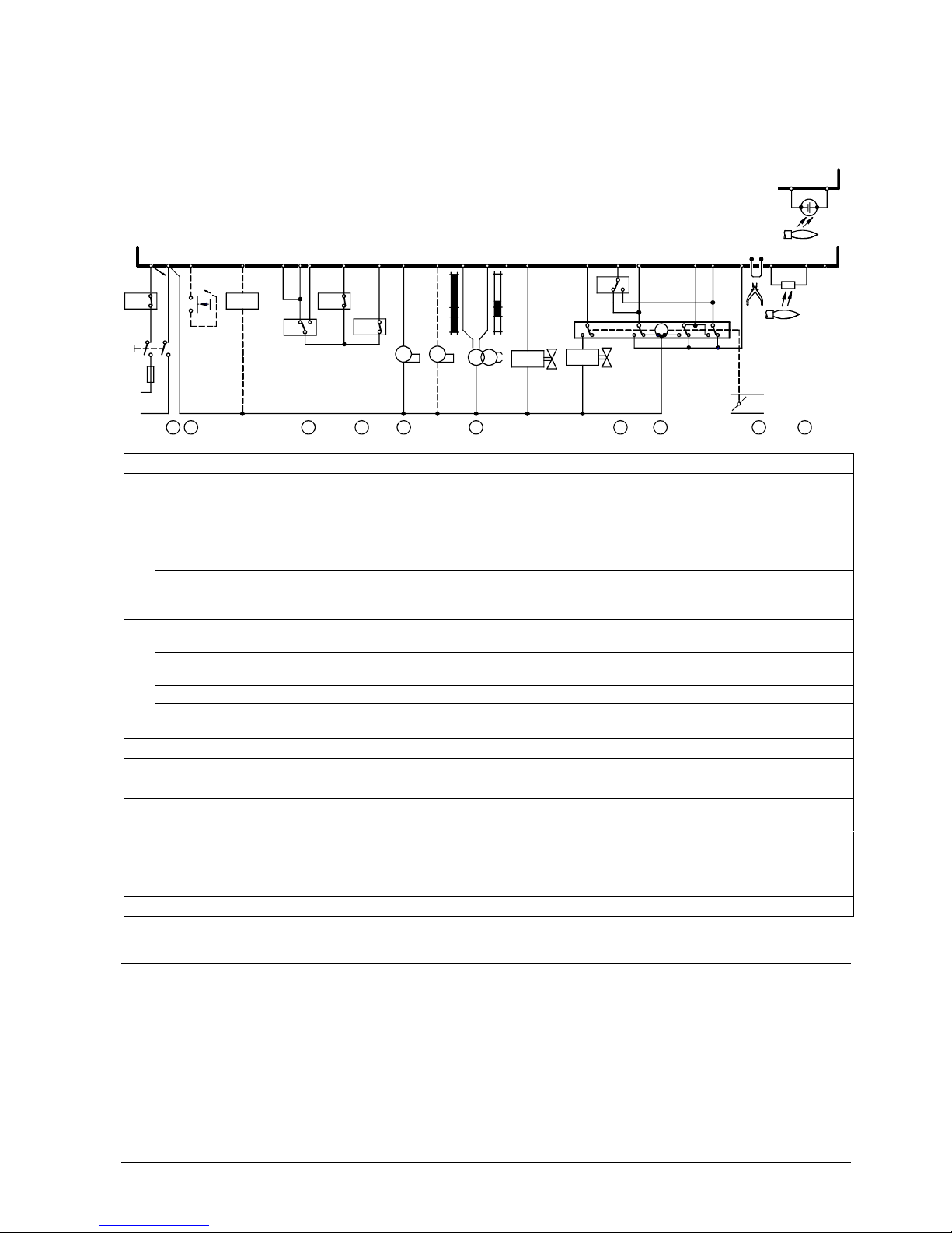
Engineering notes
· Install switches, fuses, earthing, etc., in compliance with local regulations
· Connect valves and other plant components as specified in the burner manufac-
turer’s documentation
H
N
L
EK2
AL
211 2
1(3)
3
M1 M2
R
4 5
6
7
BV2
BV1
Z
SA
15
161718
a
z
M
2019 9
LR
7153a03/0302
24
m
LK
11 10 8 22
B
vLP
141213
23
LAL2
12 3 4 5 6 7 8 9
10
QRB1...
22
24
+
RAR...
SB
W
Connect safety limit thermostats (manual reset) in the line (e.g. «SB»)
Remote reset
When connecting lockout reset button «EK2» between terminals 21 and
- 3: For remote reset only
- 1: For remote reset and remote emergency shutdown
With LAL…: Required switching capacity of
- switching devices connected between terminals 4 and 5 (refer to «Technical data»)
With LAL2... / LAL3... / LAL4...: Required switching capacity of
- switching devices connected between terminal 12 and «LP» (refer to «Technical data»)
- «LP» (refer to «Technical data»)
When using series connection, the control contacts of other devices contained in the burner plant must be connected as follows:
To terminal 4 or 5 ® contacts that must be closed from startup to controlled shutdown ® otherwise no startup
or shutdown
To terminal 12 (not with LAL1...) ® contacts that must only be closed on startup ® otherwise no startup
To terminal 14 (not with LAL1...) ® contacts that must be closed no later than at the beginning of «t3» or «t3´»
and that must remain closed until controlled shutdown occurs ® otherwise lockout
Maximum current draw, refer to «Technical data»
«Z» connected to terminal 15 ® «t3´» and «t3n»
Connection of «BV...» to terminal 20, refer to «Connection examples»
When using burners without air damper, or with an air damper not controlled and monitored by the LAL…, terminal 8 must be connected to terminal 6
Wire link «B» clearly marked on the underside of the LAL…
When wire link «B» is fitted, the LAL... initiates lockout if loss of flame occurs during operation. For repetition of
the startup sequence, wire link «B» on the plug-in section of the LAL... must be cut away. Just cutting is not
permitted!
For the permissible lengths and laying of detector cables, refer to «Flame supervision»
Mounting notes
· Ensure that the relevant safety regulations are complied with
4/20
Siemens Building Technologies CC1N7153en
HVAC Products 14.10.2002
Installation notes
· Installation work must be carried out by qualified staff
· Live and neutral conductors may not be mixed up
Electrical connection of the flame detector
It is important to achieve practically disturbance-free signal transmission:
· Never run the detector cable together with other cables
– Line capacitance reduces the magnitude of the flame signal
– Use a separate low-capacitance cable
· Observe the permissible cable lengths (refer to «Technical data»)
· Always run high-voltage ignition cables separately, with the greatest possible dis-
tance to the unit and to other cables
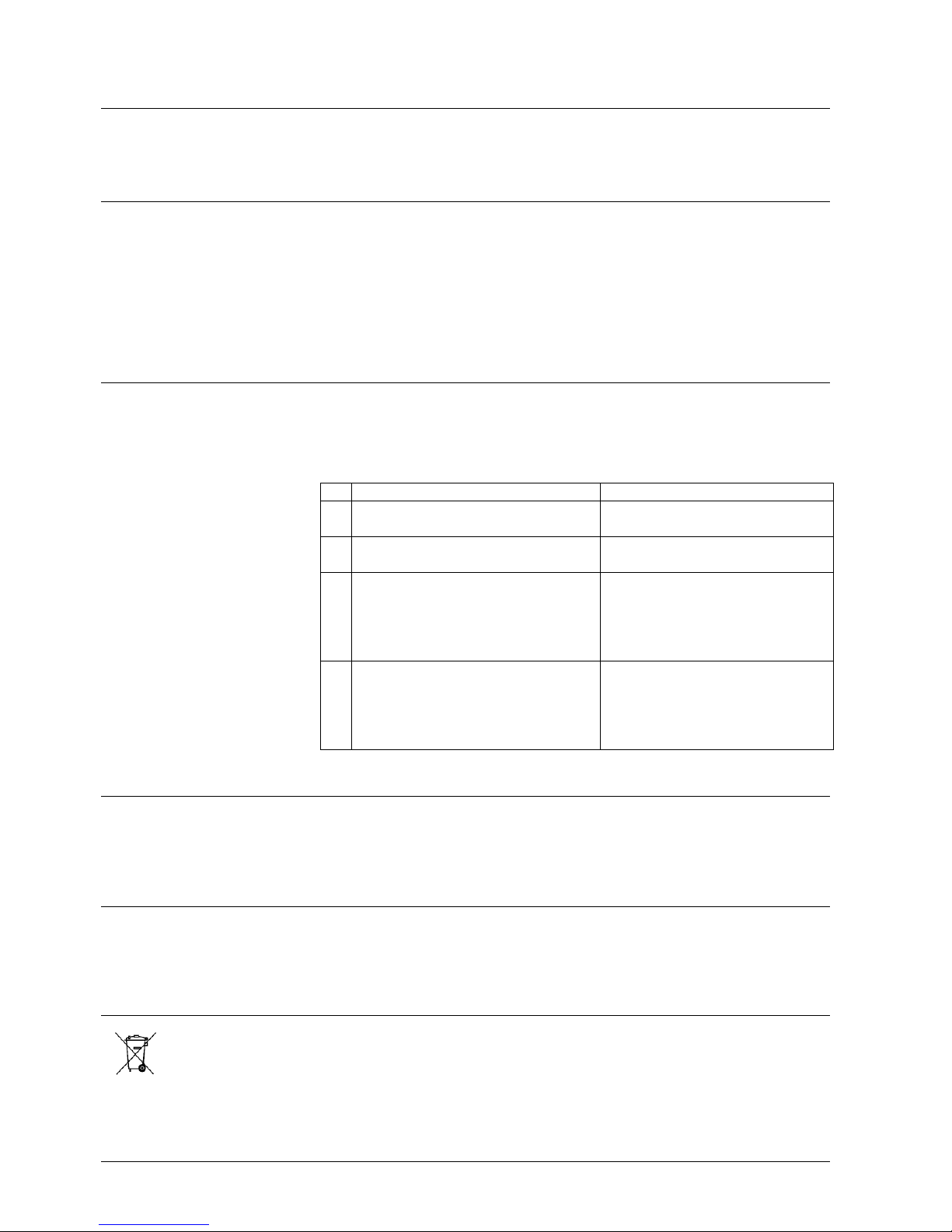
Commissioning notes
· Commissioning work must be carried out by qualified staff
· When commissioning the plant or when doing maintenance work, make the follow-
ing safety checks:
Safety check Anticipated response
a) Burner startup with flame detector
darkened
Lockout at the end of «TSA»
b) Burner startup with flame detector
exposed to extraneous light
Lockout after 40 seconds at the
latest
c) With wire strap «B»:
Simulation of loss of flame during
operation. For that purpose, darken
the flame detector during operation
and maintain this state
Lockout
d) Without wire strap «B»:
Simulation of loss of flame during
operation. For that purpose, darken
the flame detector during operation
and maintain this state
Repetition followed by lockout at the
end of «TSA»
Standards
Conformity to EEC directives
- Electromagnetic compatibility EMC (immunity) 89 / 336 EEC
- Low-voltage directive 73 / 23 EEC
Service notes
· Maintenance work must be carried out by qualified staff
· Each time a unit has been replaced, check to ensure that wiring is in an orderly
state and that the wires are firmly connected
Disposal notes
The unit contains electrical and electronic components and may not be disposed of
together with household waste.
Local and currently valid legislation must be observed.
5/20
Siemens Building Technologies CC1N7153en
HVAC Products 14.10.2002
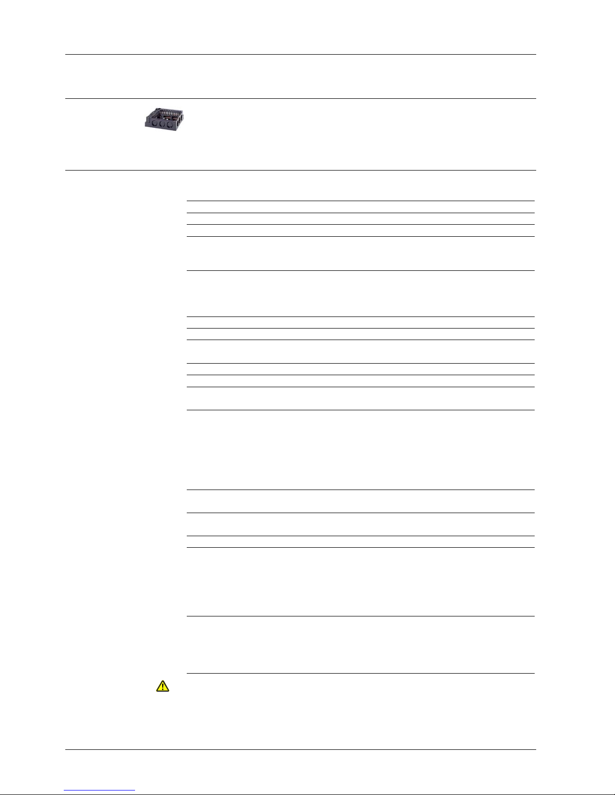
Mechanical design
- Plug-in design
- Exchangeable unit fuse (including spare fuse)
Difference to LAL1... / LAL2... / LAL4...:
- Extraneous light does not initiate lockout
– during burner off times
– during the prepurge time
- Extraneous light prevents burner startup
- Made of impact-proof and heat-resistance black plastic
- Lockout reset button with viewing window; located behind it:
– Lockout warning lamp
– Lockout indicator
- coupled to the spindle of the sequence switch
- visible in the transparent lockout reset button
- uses easy-to-remember symbols to indicate the type of fault and the point
in time lockout occurred
- Base and plug-in section of the LAL... are designed such that only burner controls
of the LAL... family can be plugged in
- 24 connection terminals
- Auxiliary terminals «31» and «32»
- 3 earth terminals terminating in a lug for earthing the burner
- 3 neutral conductor terminals
– prewired to terminal 2
- 14 knockout holes for cable entry by means of cable glands
– 8 at the side
– 6 in the bottom of the base
- 6 lateral threaded knockout holes for cable entry glands Pg11 or M20
Type summary
Switching times are given in the order of the startup sequence, valid for 50 Hz mains frequency. At 60 Hz frequency, switching times
are about 17 % shorter.
Flash steam generators Universal use Medium- or heavy-oil
burners
Flame supervision with QRB1... or QRC1... for blue-flame
burners
LAL1.25
LAL4.25A27
Flame supervision with QRB1... or RAR...
Choice of air pressure supervision
Choice of semiautomatic startup
LAL2.14 LAL2.25 LAL2.65
Same as LAL2.25 with the following exception:
No lockout, but prevention of startup in the case of extraneous light
Special applications such
as incinerator plants
LAL3.25
t1 10 s 22.5 s 67.5 s
TSA 4 s 5 s 5 s
t3 2 s 2.5 s 2.5 s
t3´ From the start ¹)
t3n 10 s 15 s 15 s
t4 8 s 7.5 s 7.5 s
t5 4 s 7.5 s 7.5 s
t6 10 s 15 s 15 s
t7 2 s 2.5 s 2.5 s
t8 30 s 47.5 s 92.5 s
t10 6 s 10 s 10 s
t11 Optional
t12 Optional
t13 10 s 15 s 15 s
t16 4 s 5 s 5 s
t20 32 s 35 s 12.5 s
¹) With air pressure supervision: From the time the air pressure signal is received
LAL...
LAL3.25
Housing
Plug-in base
6/20
Siemens Building Technologies CC1N7153en
HVAC Products 14.10.2002
Ordering
When ordering, please give full type reference according to «Type summary».
Accessories
Plug-in base
- With Pg11 threads for cable entry glands AGM410490500
- With M16 threads for cable entry glands
A
GM13.1
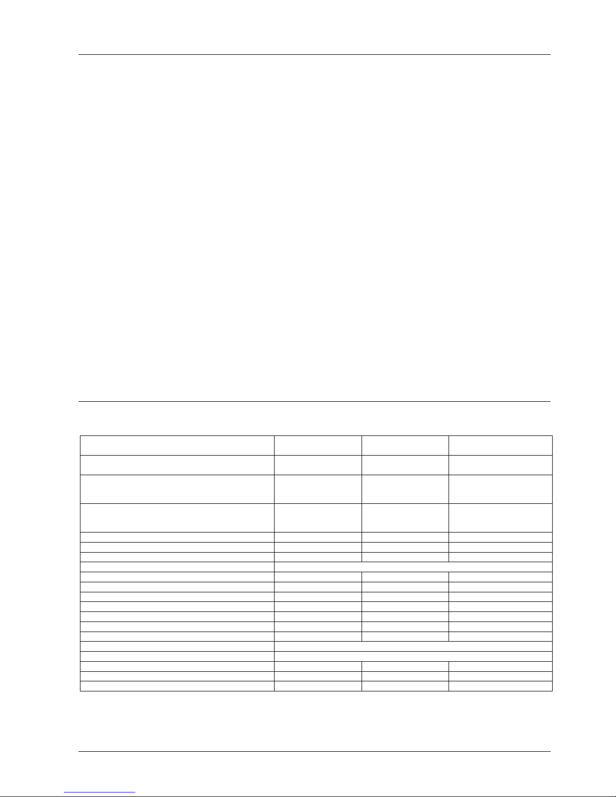
Technical data
Mains voltage
- With LAL1... / LAL2... / LAL3... incl.
AC 230 V –15 / +10 %
AC 100 V –15 %...AC 110 V +10 %
Mains frequency 50...60 Hz ±6 %
Unit fuse (built-in) T6,3H250V to DIN EN 60 127
Primary fuse (external) max. 10 A (slow)
Weight
- LAL...
- Plug-in base
approx. 1,000 g
approx. 165 g
Flame detectors:
- QRB1...
- QRC1...
- RAR...
refer to Data Sheet 7714
refer to Data Sheet 7716
refer to Data Sheet 7713
Power consumption approx. AC 3.5 VA
Mounting position optional
Degree of protection IP 40, when fitted, with the exception of the
connection area (terminal base)
Safety class
II
Perm. input current at terminal 1 max. 5 A (peaks of 20 A / 20 ms)
Perm. current rating of control terminals
3, 6, 7, 9...11 and 15...20
max. 4 A (peaks of 20 A / 20 ms)
Required switching capacity of switching
devices
- Between terminals 4 and 5
- Between terminals 4 and 12
- Between terminals 12 and «LP»
- Between terminals 4 and 14
- «LP»
1 A, AC 250 V
1 A, AC 250 V
1 A, AC 250 V
5 A (peaks of 20 A)
5 A
Degree of protection IP 00
Cable connection screw terminal
cross-sectional area of wire: 0.5...1.5 mm²
With stranded wires use adequate ferrules
Transport
DIN EN 60 721-3-2
Climatic conditions class 2K2
Mechanical conditions class 2M2
Temperature range -50...+60 °C
Humidity < 95 % r.h.
Operation
DIN EN 60 721-3-3
Climatic conditions class 3K5
Mechanical conditions class 3M2
Temperature range -20...+60 °C
Humidity < 95 % r.h.
Condensation, formation of ice and ingress of water are not permitted!
General unit data LAL...
Plug-in base AGM...
Environmental
conditions
 Loading...