

Siemens LAE10, LFE10 Quick Manual
Landis & Staefa Division CC1N7781E June 01, 1999 1/8
7
781
Flame Safeguards
LAE10
LFE10
Series 02
Supplementary data sheets 7712 and 7713
Flame safeguards for burners with intermittent operation.
For safety reasons - self-test of flame supervision circuit, etc. - at least one controlled
shutdown is required every 24 hours.
For flame supervision systems for continuous operation, refer to data sheet 7783.
The LAE10 is used for the supervision and indication of oil flames, the LFE10
for gas and oil flames.
The LAE10 / LFE10 and this data sheet are intended for use by OEMs which
integrate the flame safeguards in their products.
The LAE10 is designed for the supervision of oil flames in connection with selenium
photocell detectors RAR...
The LFE10 is suited for the supervision of gas flames and luminous or blue-burning oil
flames in connection with UV detectors QRA... or a flame rectification probe.
Both types of flame safeguards are used primarily in conjunction with the LEC1 burner
control on the following applications:
– Dual-supervision of burners
Supervision of the main flame or of the pilot and main flame by two identical or
different types of flame detectors
– Supervision of forced draught oil / gas burners
Supervision of the flame with different types of detectors, depending on the
operating mode
– Multi-flame supervision
Plants with several burners whose flames must be supervised individually by one or
several detectors, whose startup and supervision, however, should or must be
carried out centrally and simultaneously by only one burner control
– The flame safeguards can also be used in connection with other types of burner
controls provided the given combination and selected circuitry do not impair the
burner control’s safety functions
– The flame safeguards are also used as flame indication units in combustion plant
with manual startup
ISO 9001
Use

2/8 CC1N7781E June 01, 1999 Landis & Staefa Division
To avoid injury to persons, damage to property or the environment, the
following warning notes should be observed!
It is not permitted to open, interfere with or modify the units!
• Before performing any wiring changes in the connection area of the LAE10 / LFE10,
the flame safeguard must be completely isolated from the mains supply!
• Check the wiring and all safety functions!
• Ensure that the drop out delay time of relay «d» does not exceed 50 ms (also refer
to «Connection examples»)!
• The relevant national safety regulations must be complied with!
• Locate the ignition and detector electrodes such that the ignition spark cannot arc
over to the detector electrode!
→ Risk of electric overloads
• Locate and adjust the flame detector such that only the flame to be supervised will
be detected
• Protect the UV cell adequately against UV radiation emitted by
– halogen lamps
– welding equipment
– special lamps
– ignition sparks
– high energy x-rays and gamma rays
• Installation and commissioning work may only be carried out by qualified staff!
• Observe the permissible lengths and shielding of the detector cables!
→ Refer to «Technical data»!
• Always run the ignition cables separate from the unit and other cables while
observing the greatest possible distances!
• Before putting the flame safeguard into operation, check the wiring carefully!
The LAE10 / LFE10 are of plug-in design and consist of power section, flame signal
amplifier, flame relay, an auxiliary relay for controlling the UV detector or the flame
simulation test, and a flame indication lamp located in the unit cover behind a viewing
window.
The electrical circuit is intrinsically safe in compliance with the relevant regulations
and - in connection with LEC1 burner controls - is tested in respect of proper
functioning each time the burner is started up.
The flame safeguards can be mounted in any position directly on the burner, in
control panels, or on the front of a panel.
There are two types of plug-in bases available, designed for cable entry from the front,
the side or below.
Two earth terminals provide looping facilities for the earth connections of other burner
plant components such as ignition transformers (the flame safeguards themselves are
double-insulated!).
The plug-in bases - like the housing - are made of impact-proof and heat-resistant
plastic.
For illustrations of the bases and other notes, refer to «Base versions» and
«Dimensions».
– LAE10:
Automatic light simulation test by increasing the sensitivity of the amplifier during
the burner off and purge times, as programmed by the LEC1 burner control
– LFE10:
Automatic testing of the UV detector by increasing the operating voltage of the UV
tube during the burner off and purge times, as programmed by the LEC1 burner
control
Warning notes
Engineering notes
Mounting notes
Installation notes
Mechanical design
Special features
Landis & Staefa Division CC1N7781E June 01, 1999 3/8
– UV detector QRA... (refer to data sheet 7712)
– Selenium photocell detectors RAR7 and RAR8 (refer to data sheet 7713)
– Flame rectification probe
Flame supervision by making use of the electrical conductivity of the flame in
conjunction with the rectifying effect is only possible with gas and blue-flame
burners.
Since the flame signal amplifier responds only to the d.c. component of the flame
signal (ionization current), a short-circuit across the detector electrodes cannot
simulate a flame signal.
CE conformity Mains voltageAC 220 V -15 %...AC 240 V +10 %
According to the directives of the European Union AC 100 V -15 %...AC 110 V +10 %
Electromagnetic compatibility EMC
89 / 336 EEC incl. 92 / 31 EEC Mains frequency 50...60 Hz ±6 %
Directive for gas appliances 90 / 396 EEC
Low voltage directive 73 / 23 EEC Prefuse (external) max. 10 A (slow)
Environmental conditions Power consumption 4.5 VA
Transport IEC 721-3-2
Climatic conditions class 2K2 Max. contact rating 2 A
Temperature range -20...+60 °C
Humidity < 95 % r.h. Degree of protection IP 40
Mechanical conditions class 2M2 provided cable entry is in
Operation IEC 721-3-3 compliance with IP 40
Climatic conditions class 3K5
Temperature range -20...+60 °C Mounting orientation optional
Humidity < 95 % r.h.
Condensation, formation of ice and ingress
of water are not permitted!
LAE10 LFE10
Weight without plug-in base 305 g 395 g
Weight with normal plug-in base 380 g 470 g
Weight with high plug-in base 415 g 505 g
Flame supervision Series 02
LFE10 LFE10 LAE10
Rectification probe UV detector Selenium cell
Required min. detector current in µA
- At AC 100 V and AC 220 V min. 8 150 8
- At AC 110 V and AC 240 V min. 9 200 8
Max. possible detector current in µA
- At AC 100...110 V and AC 220...240 V approx. 100 approx. 650 approx. 25
Perm. length of connecting cables 20 m ¹) 20 m ¹) 20 m ²)
¹) In case of greater distances, use low-capacitance cable (total max. 2 nF), such as single-core RG62
²) Run detector cables separately, at least 5 cm away from other cables and, in case of greater distances, use
selenium photocell detector RAR8
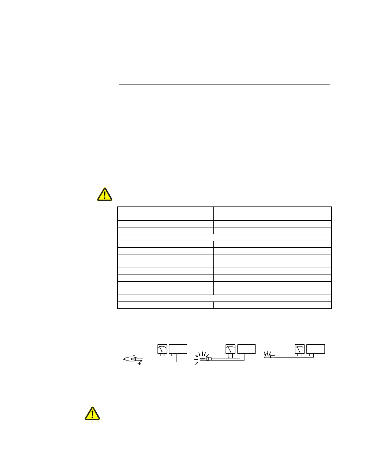
A
C
FE
M
QRA...
Illumination of flame
Electrolytic capacitor 100 µF, DC 10 V
Detector electrode
Microammeter
UV detector
Ignition may affect the ionization current!
Remedy: exchange the connections on the primary side of the ignition transformer
Flame detectors
Technical data
Measurement circuits
FE
M
+-
LFE10
810
QRA...
A
M
+-
LFE10
109
C
-
+
A
M
+-
910
LAE10
77 81a07 / 119 8
-
+
+
 Loading...