

Silicon Piezoresistive
Relative Pressure Sensor
Features
• Low pressure and temperature hysteresis
• Fast response
• High sensitivity and linearity
• Fatigue free monocrystaline silicon diaphragm
giving high load cycle stability
• High long term stability
• Built in silicon temperature sensor
• Media compatible stainless housing
KPY 51-R
KPY 56-R
Stainless Steel Package
Type and
Symbol Pressure Range Unit Ordering Code
Marking
KPY 51 R
P
… P
0
0 … 0.25 bar Q62705-K174
N
KPY 52 R 0 … 0.6 Q62705-K171
KPY 53 R 0 … 1.6 Q62705-K176
KPY 54 R 0 … 4 Q62705-K178
KPY 55 R 0 … 10 Q62705-K180
KPY 56 R 0 … 25 Q62705-K182
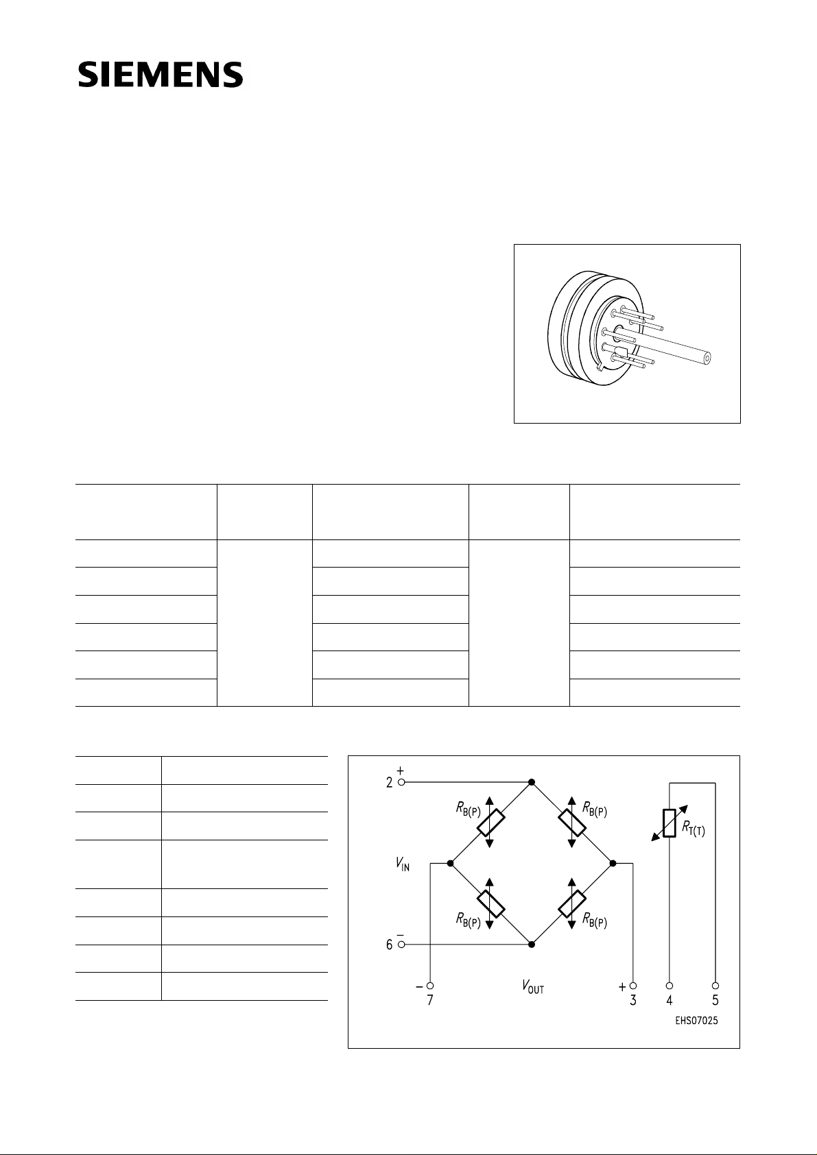
Pin Configuration
1 Capillary tube
2+
3 − V
V
IN
OUT
4 Temperature sensor
(typ.
R
= 2 kΩ)
25
5 Temperature sensor
6 −
7+V
V
IN
OUT
8 Not connected
Semiconductor Group 1 02.97
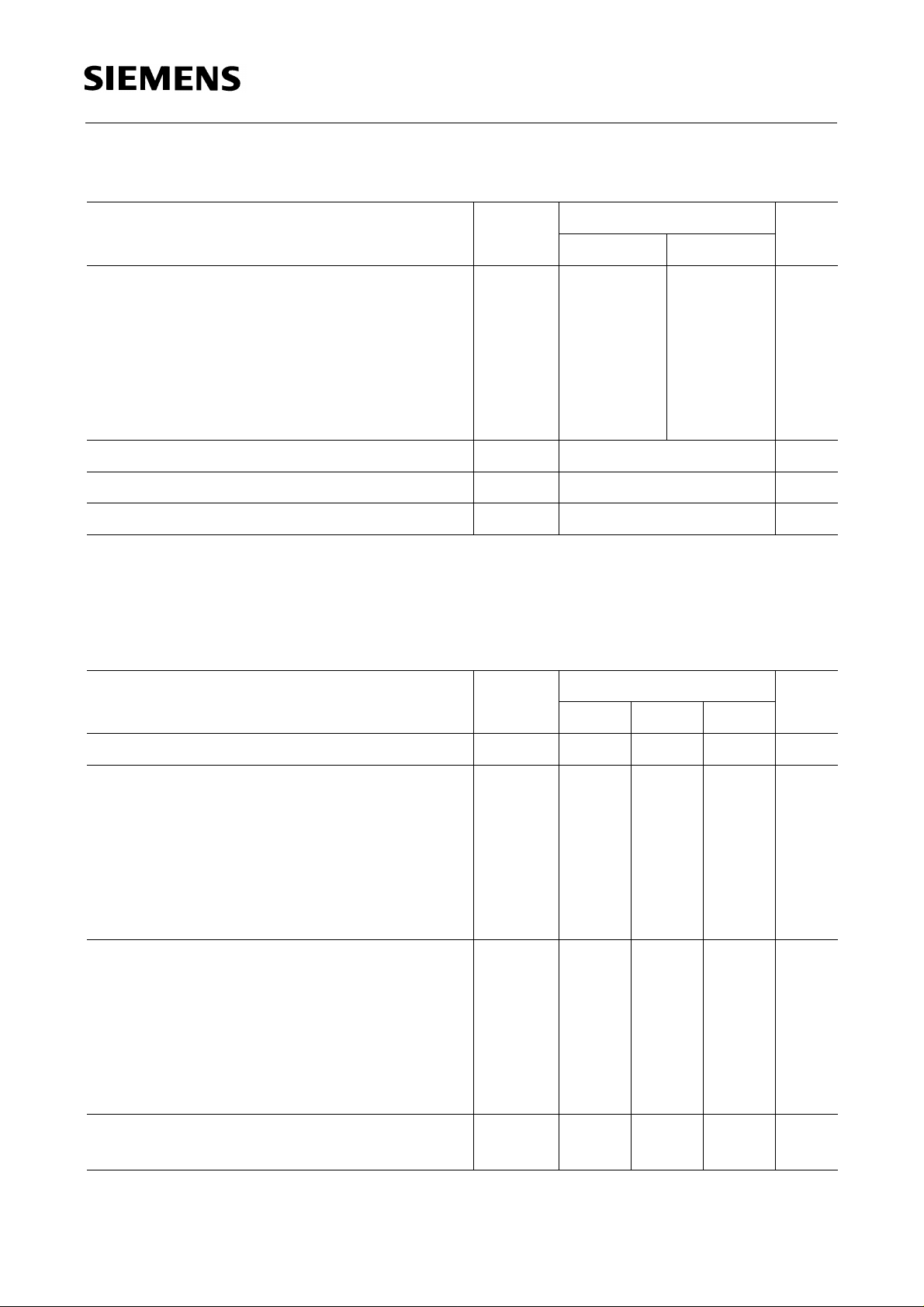
Absolute Maximum Ratings
Parameter Symbol Limit Values
Frontside Rearside
KPY 51-R
KPY 56-R
1)
Unit
Pressure overload
KPY 51 R
KPY 52 R
KPY 53 R
KPY 54 R
KPY 55 R
KPY 56 R
Operating temperature range
Storage temperature range
Supply voltage
1) Frontside coupling applies pressure onto chip face.
Rearside coupling applies pressure through Kovar centre tube.
P
T
T
V
MAX
A
stg
IN
2
6
10
16
30
75
2
6
10
16
30
40
− 40 …+ 125 ˚C
− 50 …+ 130 ˚C
12 V
bar
Electrical Characteristics
T
= 25 ˚C and VIN = 5 V, unless otherwise specified.
at
A
Parameter Symbol Limit Values Unit
min. typ. max.
Bridge resistance
Sensitivity
Output voltage
Offset voltage
P = P
0
KPY 51 R
KPY 52 R
KPY 53 R
KPY 54 R
KPY 55 R
KPY 56 R
KPY 51 R
KPY 52 R
KPY 53 R
KPY 54 R
KPY 55 R
KPY 56 R
R
s
V
V
B
4 − 8kΩ
mV/
16.8
11.0
5.6
4.0
1.8
0.88
fin
21
33
45
80
90
110
0
24.0
15.0
8.8
6.0
2.6
1.2
30
45
70
120
130
150
32.0
24.0
12.5
9.0
4.0
2.0
40
72
100
180
200
250
Vbar
mV
mV
− 25 −+ 25
Semiconductor Group 2

KPY 51-R
KPY 56-R
Electrical Characteristics (cont’d)
T
= 25 ˚C and VIN = 5 V, unless otherwise specified.
at
A
Parameter Symbol Limit Values Unit
min. typ. max.
Linearity error(Best fit straight line)
P
= P0… P
0
N
KPY 51 … 55 R
KPY 56 R
Pressure hysteresis
P
= P0, P2 = PN, P3 = P
1
KPY 51 … 56 R
0
F
P
L
−
−
H
± 0.15
± 0.15
± 0.35
−
% V
%
−± 0.1 −
Electrical Characteristics
at
T
= 25 ˚C, T2 = 80 ˚C, T3 = 25 ˚C and VIN = 5 V, unless otherwise specified.
1
Parameter Symbol Limit Values Unit
min. typ. max.
Temperature coefficient of
KPY 51 R
KPY 52 R
KPY 53 R
KPY 54 R
KPY 55 R
KPY 56 R
V
fin
TC
Vfin
− 0.20
− 0.20
− 0.20
− 0.20
− 0.20
− 0.20
%/K
−
−
−
−
−
−
− 0.09
− 0.12
− 0.13
− 0.14
− 0.15
− 0.15
V
fin
fin
Temperature coefficient of
V
0
TC
KPY 51 R
KPY 52 R
KPY 53 R
KPY 54 R
KPY 55 R
KPY 56 R
Temperature coefficient of
R
B
TC
KPY 51 … 56 R −+ 0.095 −
Temperature hysteresis of
V
0
; V
fin
TH
KPY 51 … 56 R −± 0.2 −
Semiconductor Group 3
V0
RB
− 0.03
− 0.03
− 0.03
− 0.03
− 0.03
− 0.03
%/K
−
−
−
−
−
−
+ 0.08
+ 0.08
+ 0.05
+ 0.05
+ 0.05
+ 0.05
%/K
% v. V
fin

Package Outline
Stainless Steel Package
KPY 51-R
KPY 56-R
Weight 15.5 g Dimension in mm
Exterior Packaging
I.e. tubes, trays, boxes are shown in our Data Book “Package Information”.
Semiconductor Group 4
 Loading...