

Siemens KPY51RK Datasheet
Silicon Piezoresistive
Relative Pressure Sensor
Features
• Low pressure and temperature hysteresis
• Fast response
• High sensitivity and linearity
• Fatigue free monocrystaline silicon diaphragm
giving high load cycle stability
• High long term stability
• Built in silicon temperature sensor
• Provided for further fabrication, protection cap
KPY 51-RK
KPY 57-RK
TO-8-6
Type and
Symbol Pressure Range Unit Ordering Code
Marking
KPY 51 RK
P
… P
0
0 … 0.25 bar Q62705-K189
N
KPY 52 RK 0 … 0.6 Q62705-K190
KPY 53 RK 0 … 1.6 Q62705-K191
KPY 54 RK 0 … 4 Q62705-K193
KPY 55 RK 0 … 10 Q62705-K195
KPY 56 RK 0 … 25 Q62705-K197
KPY 57 RK 0 … 60 Q62705-K199
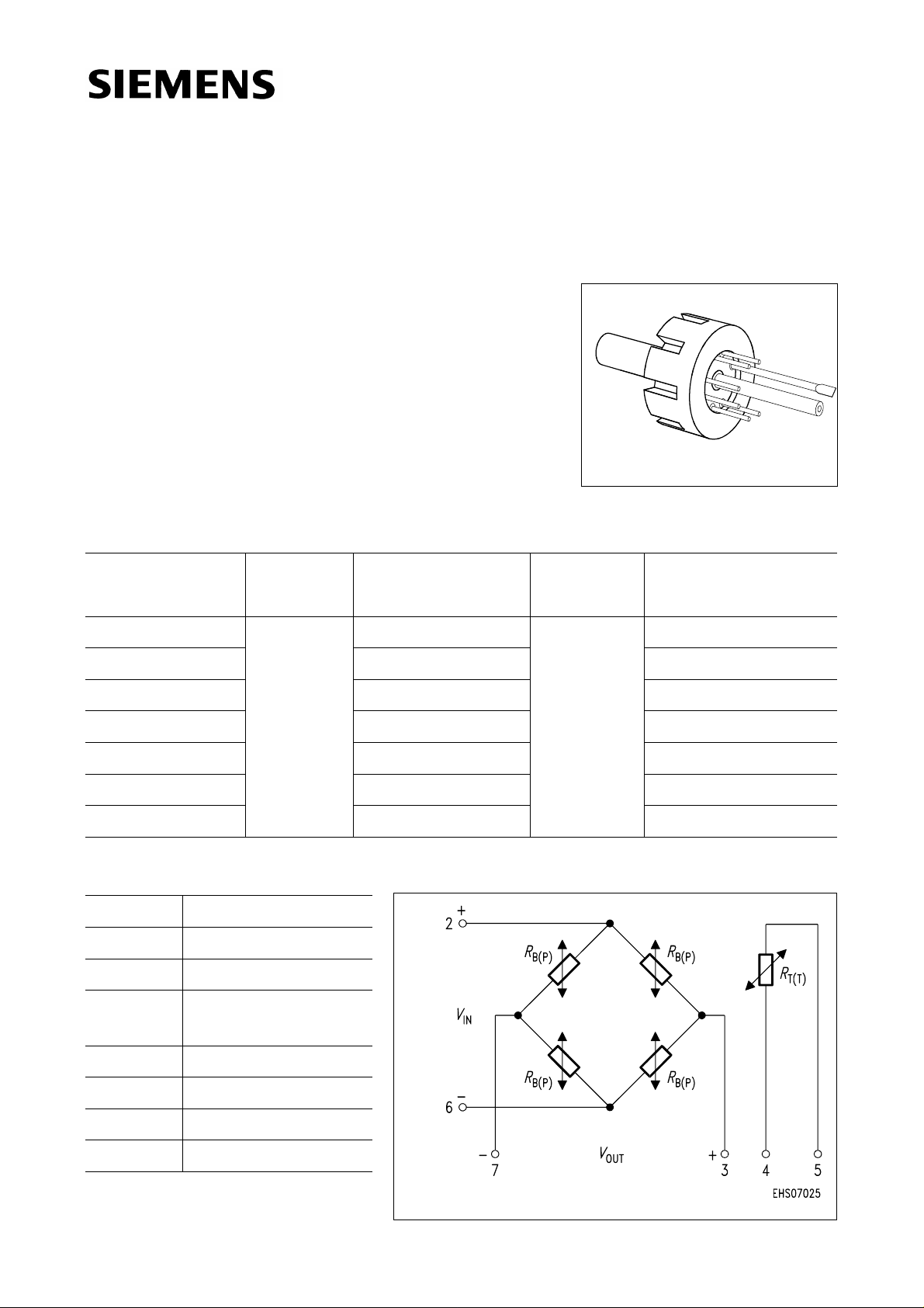
Pin Configuration
1 Capillary tube
2+
3 − V
V
IN
OUT
4 Temperature sensor
(typ.
R
= 2 kΩ)
25
5 Temperature sensor
6 −
7+V
V
IN
OUT
8 Not connected
Semiconductor Group 1 02.97
Absolute Maximum Ratings
Parameter Symbol Limit Values
Frontside Rearside
KPY 51-RK
KPY 57-RK
1)
Unit
Pressure overload
P
KPY 51 RK
KPY 52 RK
KPY 53 RK
KPY 54 RK
KPY 55 RK
KPY 56 RK
KPY 57 RK
Operating temperature range
Storage temperature range
Supply voltage
1) Frontside coupling applies pressure onto chip face.
Rearside coupling applies pressure through Kovar centre tube.
T
T
V
MAX
A
stg
IN
2
6
10
16
30
75
100
2
6
10
16
30
40
70
− 40 …+ 125 ˚C
− 50 …+ 150 ˚C
12 V
bar
Electrical Characteristics
at
T
= 25 ˚C and VIN = 5 V, unless otherwise specified.
A
Parameter Symbol Limit Values Unit
Bridge resistance
Sensitivity
Output voltage
KPY 51 RK
KPY 52 RK
KPY 53 RK
KPY 54 RK
KPY 55 RK
KPY 56 RK
KPY 57 RK
KPY 51 RK
KPY 52 RK
KPY 53 RK
KPY 54 RK
KPY 55 RK
KPY 56 RK
KPY 57 RK
R
s
V
min. typ. max.
B
4 − 8kΩ
mV/
16.8
11.0
5.6
4.0
1.8
0.88
0.47
fin
21
33
45
80
90
110
140
24.0
15.0
8.8
6.0
2.6
1.2
0.67
30
45
70
120
130
150
200
32.0
24.0
12.5
9.0
4.0
2.0
1.0
40
72
100
180
200
250
300
Vbar
mV
Semiconductor Group 2
 Loading...