

Page 1
D
GAMMA instabus
isystem
Raumtemperaturregler UP 237K
Temperature controller UP 237K
titanweiß/titanium white 5WG1 2372KB11
aluminiummetallic/
aluminum metallic 5WG1 2372KB31
DELTA style
Raumtemperaturregler UP 254K
Temperature controller UP 254K
titanweiß/metallicsilber
titanium white/metallic silver 5WG1 2542KB13
platinmetallic/
platinum metallic 5WG1 2542KB43
Bedien und Montageanleitung
Operating and Mounting Instruction
Stand: August 2012
Issued: August 2012
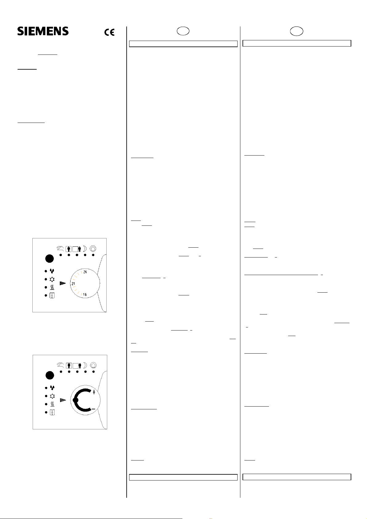
Bild 1: Raumtemperaturregler mit Drehknopf zur
Sollwerteinstellung in °C
Figure 1: : Room temperature controller with rotary
knob for setting the setpoint value in °C
Bild 2: Raumtemperaturregler mit Drehknopf
zur Sollwertverschiebung
Figure 2: Room temperature controller with rotary
knob for shifting the setpoint value
A5E02926638A DS03 Seite 1 von 3 page 1 of 3
Produkt und Funktionsbeschreibung
Die Raumtemperaturregler UP 237K und UP 254K sind speziell
für den Einsatz in Räumen ausgelegt, die geheizt und / oder ge
kühlt werden und deren Raumtemperaturregelung abhängig von
bis zu vier RaumBetriebsarten (Komfortbetrieb, Pre
Komfortbetrieb, Energiesparbetrieb und Schutzbetrieb) erfolgt.
Über einen Parameter ist bei Bedarf einstellbar, dass der Regler
nicht alle vier Betriebsarten berücksichtigen soll sondern nur drei
(Komfortbetrieb, Energiesparbetrieb und Schutzbetrieb) oder nur
zwei (Komfortbetrieb und Schutzbetrieb). Der Raumtemperatur
regler ist als Zweipunktregler (Thermostat) oder als stetiger Reg
ler (P, PIRegler) einsetzbar.
Das zugehörige Applikationsprogramm vergleicht die vom Raum
temperaturregler gemessene IstTemperatur mit der gewünsch
ten SollTemperatur und berechnet daraus die zugehörige Stell
größe. Diese wird dann entweder als Schaltbefehl (Ein/Aus) an
Schaltaktoren zum Ansteuern von elektrothermischen Stellan
trieben bei einer Zweipunktregelung oder als Stellbefehl (0...
100 %) zum Ansteuern eines motorisch angetriebenen Ventil
stellantriebes bei stetiger Regelung übertragen.
Diese Raumtemperaturregler sind nur zusammen mit einem Bus
Transceiver Module (BTM) UP 117 und dem zugehörigen Appli
kationsprogramm einsetzbar.
LEDAnzeigen
Die übersichtliche und selbsterklärende Bedienoberfläche ent
hält außer einem Taster und einem Drehknopf an ihrem oberen
Rand 5 grün leuchtende Leuchtdioden (LED) zur Anzeige, ob der
„Handbetrieb“ aktiviert ist sowie der aktuellen RaumBetriebsart
und am linken Rand der Bedienoberfläche zwei rot leuchtende
LED`s und 2 zweifarbig leuchtende LED`s . Die zweifarbigen
LED`s werden zur Anzeige, ob das Heizventil geöffnet ist (LED
leuchtet rot) oder das Kühlventil (LED leuchtet gelb) geöffnet ist,
verwendet. Leuchten diese LED`s nicht, so sind beide Ventile
geschlossen.
Über je eine rote LED wird angezeigt, ob ein Fenster geöffnet ist
oder ein Taupunktalarm ansteht.
Taster
Durch kurzes Betätigen des Tasters auf dem Regler erfolgt im Au
tomatikbetrieb (die LED zur Anzeige des Handbetriebs leuchtet
nicht) die Umschaltung jeweils zwischen „Komfortbetrieb“ und
„PreKomfortbetrieb“ (bei vier Betriebsarten) bzw. zwischen
„Komfortbetrieb“ und „Energiesparbetrieb“ (bei drei Betriebsar
ten). Außerdem kann durch ein kurzes Drücken bei aktivem
Energiespar oder Schutzbetrieb eine „KomfortVerlängerung“
gestartet werden. Durch ein langes (z.B. > 1 s, aber < 3 s) Drü
cken des Tasters während einer laufenden KomfortVerlängerung
kann
diese jederzeit beendet und auf die Raumbetriebsart vor Beginn
der KomfortVerlängerung zurückgesprungen werden.
Durch sehr langes (> 3 s) Betätigen des Tasters kann von Auto
matik auf Handbetrieb umgeschaltet werden. Im Handbetrieb
kann jede RaumBetriebsart dauerhaft aktiviert und nicht durch
ein BusTelegramm geändert werden. Ist der Handbetrieb akti
viert, so wandert bei jeder kurzen Betätigung des Tasters die
Leuchtanzeige der aktuellen Betriebsart von der aktuellen Positi
on schrittweise zum jeweils nächsten BetriebsartSymbol, bis die
äußerste rechte oder linke Position erreicht ist und von dort wie
der zurück. Erfolgt während einer Wartezeit von ca. 3 Sekunden
keine
erneute kurze TasterBetätigung, so wird die angezeigte Raum
Betriebsart aktiviert und dies über den Bus gemeldet. Wird der
Taster im „Handbetrieb“ sehr lange (> 3 s) betätigt, so wird hier
durch auf Automatikbetrieb und gleichzeitig auf Komfortbetrieb
umgeschaltet. Ist ein Präsenzmelder installiert, so wird ein kur
zes Betätigen des Tasters im Automatikbetrieb ignoriert.
Drehknopf
Der Regler wird mit zwei Drehknöpfen geliefert: einem in den
Regler gesteckten Drehknopf zum Verschieben des Basis
Sollwertes (siehe Bild 2) zu einem höheren bzw. niedrigeren
Wert und einem zweiten zum direkten Einstellen des Sollwertes
(siehe Bild 1) im Bereich von 16 bis 26 °C.
Wird anstelle der SollwertVerschiebung mit einstellbarem Ver
schiebebereich die direkte SollwertEinstellung in Grad Celsius
gewünscht, so ist der eingesteckte gegen den mitgelieferten
Drehknopf auszuwechseln und im ParameterFenster „Funktio
nen / Objekte“ der Parameter „SollwertEinstellung“ auf „direkt in
°C“ zu setzen.
Inbetriebnahme
Zur Inbetriebnahme eines Reglers mit Hilfe der ETS (Engineering
Tool Software) ist der Regler zuvor zusammen mit dem passen
den DELTA Rahmen auf ein Bus Transceiver Module (BTM) UP
117 zu stecken, das zur Stromversorgung des Reglers und zur
Datenübertragung über den KNXBus dient.
Nach Abziehen des Drehknopfes zur SollwertVerschiebung wer
den die Aussparungen für den InbetriebnahmeTaster und die
InbetriebnahmeLED des Reglers sichtbar.
: Das Bus Transceiver Modul UP 117 und der zugehörige
Hinweis
DELTA Rahmen sind nicht im Lieferumfang enthalten und müs
sen zusätzlich bestellt werden.
Weitere Informationen
http://www.siemens.de/gamma
Product and Applications Description
The room temperature controller UP 237K and UP 254K are es
pecially designed for usage in rooms which are heated and/or
cooled and whose temperatures are controlled depending on up
to four room operating modes (comfort mode, precomfort
mode, energysavings mode and protection mode). As required,
a parameter can be used to set that the controller does not con
sider all four operating modes but rather only three (comfort
mode, energysavings mode and protection mode). The room
temperature controller can be used as a twopoint control (ther
mostat) or as a continuous controller (P or PI controller).
The associated application program compares the actual tem
perature measured by the temperature controller with the re
quired setpoint temperature and calculates the relevant control
value. This control value is then either transmitted as a switching
command (ON/OFF) to switch actuators to control electrother
mal valve drives in twostep control or as a control command
(0... 100 %) for controlling a motordriven valve drive in con
tinuous control.
These Room temperature controller can only function together
with the necessary Bus Transceiver Module (BTM) UP 117 and
the associated application program.
LED displays
Along with a button and a rotary button on its upper edge, the
clear and selfexplanatory user interface contains 5 green illumi
nating light emitting diodes (LED) to display whether "manual
operation" is activated as well as the current room operating
mode and two red illuminating LEDs and 2 duocolor illuminating
LEDs on the left edge. The duocolor LEDs are used to display
whether the heating valve (LED is lit in red) or the cooling valve
(LED is lit in yellow) is open. If these LEDs are not illuminated,
then both valves are closed.
A red LED is used to display whether a window is open or
whether a dew point alarm is pending.
Button
Briefly pressing the button on the controller causes switching in
automatic mode (the LED for the display of manual operation is
not lit) each time between "comfort mode" and "precomfort
mode" (with four operating modes) or between "comfort mode"
and "energysavings mode" (with three operating modes). More
over briefly pressing the button during active energysavings or
protection mode starts a "extended comfort mode". Pressing and
holding down (e.g.> 1 s, but < 3 s) the button during continuous
extended comfort mode can cause this to end at any time and
jump back to the room operating mode before the start of the
extended comfort mode.
Holding down the button for a longer time (> 3 s) can cause
switching from automatic to manual operation. In manual opera
tion every room operating mode can be permanently activated
and not changed by a bus telegram. If manual operation is acti
vated, then each time the button is pressed briefly the light dis
play of the current operating mode wanders gradually from the
current position to the next operating mode symbol until the ex
treme right or left position is reached and from there back again.
If during a waiting time of around 3 seconds no
renewed brief pressing of the button occurs, then the displayed
room operating mode will be activated and this reported by the
Bus. If the button in "manual operation" is pressed for a very long
(> 3 s) time, then the system will be switched to automatic op
eration and at the same time to comfort mode. If a presence de
tector is installed, then a brief pressing of the button in auto
matic operation is ignored.
Rotary button
The controller is supplied with two rotary buttons: one inserted
in the controller for shifting the basic setpoint (see figure 2)
value to a higher or lower value and a second for directly setting
the setpoint value (see figure 1) in the range of 16 to 26 °C.
If instead of shifting the setpoint value with the adjustable shift
ing range, direct setpoint value setting in degrees Celsius is de
sired, then the inserted rotary button should be exchanged with
the delivered rotary button and the parameter "setpoint value
setting" should be switched to "directly in °C" in the "Functions /
objects" parameter window.
Commissioning
For commissioning a controller with the help of ETS (Engineering
Tool Software), the controller together with the suitable DELTA
frame must first be inserted into a Bus Transceiver Module (BTM)
UP 117 which serves to supply power to the control and to
transmit data via the KNX Bus.
After removing the rotary button for setpoint value shifting, the
recess for the commissioning button and the commissioning LED
of the control are visible.
The bus transceiver module UP 117 and the associated
Note:
DELTA frame are not supplied and must be ordered separately.
Additional Information
http://www.siemens.com/gamma
GB
Page 2
A6
A7
A8
A9
A10
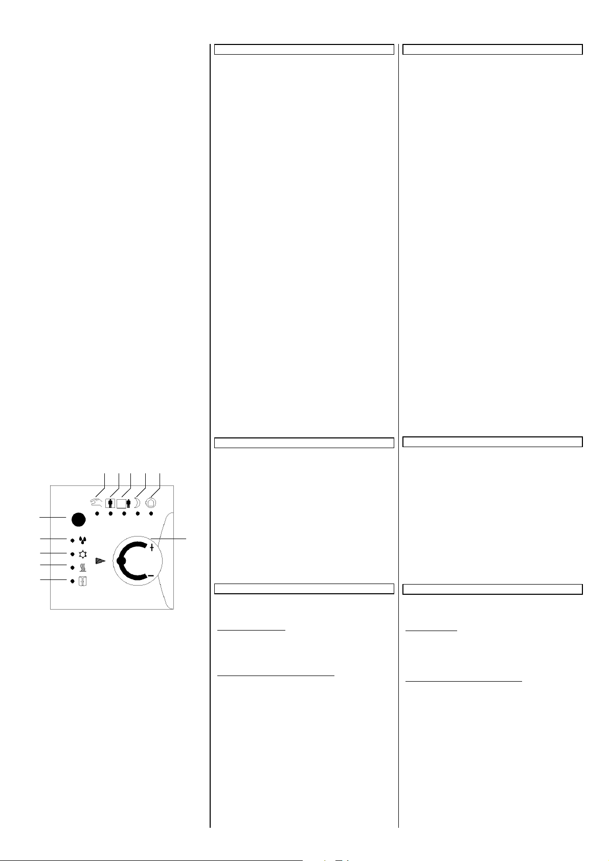
Bild 3: Lage der Bedien und Anzeigeelemente
Figure 3.: Location of the operating and display elements
A5E02926638A DS03 Seite 2 von 3 page 2 of 3
A2 A3 A4 A5
A1
Technische Daten
Spannungsversorgung
• erfolgt über das Bus Transceiver Module UP 117
Bedienelemente
• 1 Drehknopf zur manuellen Sollwerteinstellung
(Stellbereich und Einstellart sind abhängig von Parameterein
stellung und Drehknopf)
• 1 Taster zum Umschalten der Raumbetriebsart
Anzeigeelemente
• 5 grüne LED`s: für Handbetrieb und für die aktuelle Betriebs
art (Komfort, PreKomfort, Energiesparbetrieb, Schutzbetrieb)
• 2 rote LED`s für Taupunktalarm und geöffnetes Fenster
• 2 rot/gelbe LED`s für Heiz/Kühlbetrieb
Temperaturmessung
• Messbereich: 0 ... + 40 °C
• Auflösung: 0,08 K
• Genauigkeit in Bezug zur Fühlertemperatur:
± 1,0 K bei Referenzbedingungen,
± 2,0 K bei Umgebungsbedingungen und im Messbereich
Anschlüsse
• 10 polige Steckerleiste zum Aufstecken und Verbinden mit
dem Bus Transceiver Module UP 117
Mechanische Daten
• Abmessungen:
Regler UP 237K zu isystem (L x B x T): 55 x 55 x 16 mm
(ohne Feder)
Regler UP 254K zu DELTA style (L x B x T):
68 x 68 x 20 mm (ohne Feder)
• Gewicht: ca. 30 g (UP 237K)
• Gewicht: ca. 40 g (UP 254K)
Elektrische Sicherheit
• Schutzart (nach EN 60529): IP 20
Umweltbedingungen
• Klimabeständigkeit: EN 5009022
• Umgebungstemperatur im Betrieb: 5 ... + 45 °C
• Lagertemperatur: 25 ... + 70 °C
• rel. Feuchte (nicht kondensierend): 5 % bis 93 %
Prüfzeichen
• KNX EIB
Lage und Funktion der Anzeige und Bedienelemente
A1 Anzeige grün: leuchtet bei Handbetrieb
A2 Anzeige grün: leuchtet dauerhaft bei Komfortbetrieb und
blinkt langsam bei KomfortVerlängerung
A3 Anzeige grün: leuchtet bei PreKomfortbetrieb
A4 Anzeige grün: leuchtet bei Energiesparbetrieb
A5 Anzeige grün: leuchtet dauerhaft bei Schutzbetrieb,
blinkt langsam bei DauerSchutzbetrieb
A6 Taster zum Umschalten der Betriebsart
A7 Anzeige rot: leuchtet bei Taupunktalarm
A8 Anzeige gelb: leuchtet, wenn Kühlventil geöffnet
A9 Anzeige rot: leuchtet, wenn Heizventil geöffnet
A11
A10 Anzeige rot: leuchtet, wenn Fenster geöffnet.
A11 Drehknopf zur manuellen SollwertVerschiebung (Ver
schiebebereich abhängig von ParameterEinstellung)
bzw. zur SollwertEinstellung in °C
Montage
• Das Gerät kann für feste Installation in Innenräumen, für tro
ckene Räume, zum Einbau in UPDosen verwendet werden.
Allgemeine Beschreibung
Der Regler wird zusammen mit dem zugehörigen
DELTA Rahmen auf das BTM UP 117/11 gesteckt und mit des
sen Tragrahmen verschraubt.
Montage und Inbetriebnahme (siehe Bild 4)
Das BTM UP 117/11 (B8) an der UP Dose befestigen und an
die Busleitung anschließen (siehe Montageanleitung zum
BTM UP 117/11)
Drehknopf (B1 bzw. B2) vom Regler (B3) abziehen
Regler mit DELTA Rahmen (B4) auf das BTM
UP 117/11 aufstecken und mit der Schraube (B5) festschrau
ben
InbetriebnahmeTaste (B7) drücken: InbetriebnahmeLED
(B6) leuchtet auf
Physikalische Adresse und das parametrierte Applikationspro
gramm mit Hilfe der ETS laden
Drehknopf (B1 bzw. B2) wieder aufstecken.
Technical data
Power supply
• via the bus transceiver module UP 117
Operating elements
• 1 rotary button for manual adjustment of the setpoint
(control range and type of adjustment dependent on the pa
rameter setting and type of rotary button)
• 1 button for toggling of the room operating mode and vice
versa
Display elements
• 5 green LED`s: for manual mode and for the current operat
ing mode (comfort, precomfort, energysaving, protection
mode)
• 2 red LED`s for dew point alarm and open window
• 2 red/yellow LED`s for Heating / Cooling mode
Temperature measurement
• Measuring range: 0 ... + 40 °C
• Resolution: 0.08 K
• Accuracy of the sensor temperature:
± 1.0 K under reference conditions,
± 2.0 K under ambient conditions and in measuring range
Connections
• 10pole plugin connector for connection with the bus trans
ceiver module UP 117
Mechanical data
• Dimensions:
Temperature controller UP 237K for isystem
(L x W x D): 55 x 55 x 20 mm (without spring)
Temperature controller UP 254K for DELTA style
(L x W x D): 68 x 68 x 20 mm (without spring)
• Weight: approx. 30 g (UP 237K)
• Weight: approx. 40 g (UP 254K)
Electrical safety
• Type of protection (according to EN 60529): IP 20
Environmental conditions
• Climatic withstand capability: EN 5009022
• Ambient operating temperature: 5 ... + 45 °C
• Storage temperature: 25 ... + 70 °C
• Relative humidity (not condensing): 5 % up to 93 %
Markings
• KNX / EIB
Location and function of the operating and display elements
A1 LED green: illuminates during manual mode
A2 LED green: lights up continuously in comfort mode and
blinks slowly in extended comfort mode.
A3 LED green: illuminates during precomfort mode
A4 LED green: illuminates during energysaving mode
A5 LED green: lights up continuously in protection mode,
blinks slowly in permanent protection mode
A6: Pushbutton for selection of room operating mode
A7: LED red: illuminates with dew point alarm
A8: LED yellow: illuminates if cooling valve is open
A9: LED red: illuminates if heating valve is open
A10: LED red: illuminates if open window
A11: Rotary button for manual setpoint shifting (shifting
range dependent on parameter setting) or for setpoint
adjustment in °C
Mounting
• The device can be used for permanent interior installations in
dry rooms and for insertion in flushtype boxes.
General description
The temperature controller is attached with the associated
DELTA frame to the BTM UP 117/11 and screwed to its mount
ing frame.
Mounting and commissioning (see figure 4)
Attach the bus cable and fix the BTM UP 117/11 (B8) on the
flush socket (see mounting instructions for BTM UP 117/11)
Remove rotary knob (B1 or B2) from the temperature
controller (B3)
Attach temperature controller with DELTA frame (B4) to the
BTM UP 117 /11 and secure using screw (B5)
Press programming button (B7): programming LED (B6)
illuminates
Load physical address and the configures application program
by means of the ETS
Replace rotary knob (B1 or B2).
Page 3

Bild 4: Montage des Reglers
Figure 4 : Mounting controller
Bild 5: Installationshinweise für Fühler und Temperaturregler
Figure 5: Installation references for sensors and temperatu
re controller
Bild 6: Abdichtung Installationsrohr
Figure 6: Sealing installation conduit
Technical Support
℡ +49 (911) 8957222
+49 (911) 8957223
support.automation@siemens.com
www.siemens.de/automation/supportrequest
A5E02926638A DS03 Seite 3 von 3 page 3 of 3
B1
B2
B8
B7
B6
B5
B4
B3
B1 Drehknopf zur SollwertVerschiebung
B2 Drehknopf zur SollwertEinstellung in °C
B3 Regler Heizen / Kühlen
B4 DELTARahmen
B5 Schraube zum Befestigen des Reglers am Tragrahmen
des UP 117 (Diebstahlsicherung)
B6 LED zur Anzeige Normalmodus (LED Aus) oder Adres
siermodus (LED Ein); sie erlischt automatisch nach Über
nahme der physikalischen Adresse
B7 Taste zum Umschalten zwischen Normalmodus und Ad
ressiermodus zur Übernahme der physikalischen
Adresse
B8 Bus Transceiver Module UP 117
V
V
VV
• Das Gerät darf nur von einer zugelassenen Elektrofachkraft
• Das Gerät darf in Schaltersteckdosenkombinationen einge
• Die geltenden Sicherheits und Unfallverhütungsvorschriften
• Bei der Planung und Errichtung von elektrischen Anlagen sind
Montageort (siehe Bild 5)
Bei der Montage des Reglers sind folgende Hinweise zu beach
ten:
Reglermontage an der Innenwand des zu klimatisierenden Rau
mes, gegenüber der Heizquelle:
• Auf ca. 1,5 m Höhe in der Aufenthaltszone und mindestens
• nicht an Aussenwänden
• nicht in Nischen oder hinter Vorhängen
• nicht über oder nahe bei Wärmequellen oder Regalen
• nicht an Wänden, hinter denen sich Wärmequellen wie z.B.
• nicht im Strahlungsbereich von Wärmequellen und Leucht
• nicht in Bereichen mit direkter Sonneneinstrahlung
Die Zugluft von Fenstern und Türen ist zu vermeiden!
Das geräteseitige Ende des Installationsrohres ist abzudichten,
damit kein Luftzug im Rohr entsteht, der die Messung negativ
beeinflusst, siehe Bild 6.
Demontage
Drehknopf (B1 bzw. B2) abziehen
Schraube (B5) herausschrauben
Regler zusammen mit dem DELTARahmen abziehen
BTM UP 117 (B8) entsprechend Demontageanleitung ausbauen
Allgemeine Hinweise
• Die Bedienungsanleitung ist dem Kunden auszuhändigen.
• Ein defektes Gerät ist mit einem Rücklieferschein der zustän
• Bei zusätzlichen Fragen zum Produkt wenden Sie sich bitte an
WARNUNG
installiert und in Betrieb genommen werden.
setzt werden, wenn VDE zugelassene Geräte verwendet wer
den.
sind zu beachten.
die einschlägigen Richtlinien, Vorschriften und Bestimmun
gen des jeweiligen Landes zu beachten.
50 cm von der nächsten Wand entfernt.
ein Kamin befindet
körpern wie z.B. Spotlampen
digen Vertriebsniederlassung zurückzusenden.
unseren Technical Support.
B1 Rotary button for setpoint shifting
B2 Rotary button for setpoint adjustment in °C
B3 Temperature controller heating / cooling
B4 DELTA frame
B5 Screw for securing the controller to the mounting frame
of the UP 117 (antitheft protection)
B6 LED for displaying normal mode (LED Off) or address
mode (LED On); it is automatically extinguished once
the physical address has been transferred
B7 Button for toggling between normal mode/addressing
mode for transferring the physical address
B8 Bus Transceiver Module UP 117
V
V
VV
• The device must be mounted and commissioned by an
• The device may be mounted in switch and socket combina
• The prevailing safety rules must be heeded.
• For planning and construction of electric installations, the
Mounting location (see figure 5)
Observe the following points when mounting the controller:
Controller mounted on interior wall of room to be conditioned,
visávis the heat source: :
• At ca. 1.5 m height in the room and at least 50 cm from the
next wall.
• Not on outside walls.
• Not in niches or behind curtains.
• Not above or near heat sources or shelves.
• Not on walls covering heat sources such as a chimney.
• Not in the radiation range of heat sources and lighting bodies
e.g. spotlights.
• Not in areas exposed to direct solar radiation.
The air draft of windows and doors have to be avoided!
Seal the end of the installation conduit to prevent false meas
urements due to air drafts, see figure 6.
Dismantling
Remove rotary knob (B1 or B2).
Loosen screw (B5)
Remove controller together with DELTA frame
Remove BTM UP 117 (B8) according to dismantling instructions
General Notes
• The operating instructions must be handed over to the client.
• Any faulty device is to be sent together with a return delivery
• If you have further questions concerning the product please
WARNING
authorised electrician.
tions if VDEcertified devices are used exclusively.
relevant guidelines, regulations and standards of the respec
tive country are to be considered.
note of the local Siemens office.
contact our technical support.
 Loading...