

Siemens HZM Installation Instructions Manual
HZM HZM
FRONT BACK SIDE
ALARM
1 2 3 456 7 8 9
PROGRAMMING
POINTS
Installation Instruct ions
Model HZM
Remote Conventional Zone Module
INTRODUCTION The Model HZM from Siemens Industry, Inc. is an intelligent device that connects a
single zone of conventional devices to a DLC (FireFinder-XLS System) or FS-DLC (FS250 System) device loop. The HZM can power up to fifteen compatible 2-wire, ionization or photoelectric smoke detectors or it can power one PB-1191 Beam Detector. It
can also monitor an unlimited number of shorting devices such as waterflow switches,
thermal detectors, manual stations, etc.
Each HZM can be assigned a custom message using either the Zeus Programming
Tool (FireFinder-XLS System) or the FS-CT2 (FS-250 System). Refer to the Zeus Quick
Start Manual, P/N 315-033875, or the FS-250 Programming Manual, P/N 315-049403,
as applicable. The alarm verification configuration is used only for non-shorting detectors.
The HZM supports Class A and Class B wiring. The module uses one address on the
device loop. It does not require any mechanical address programming. Use the DPU
Device Programming Unit to program and test the module.
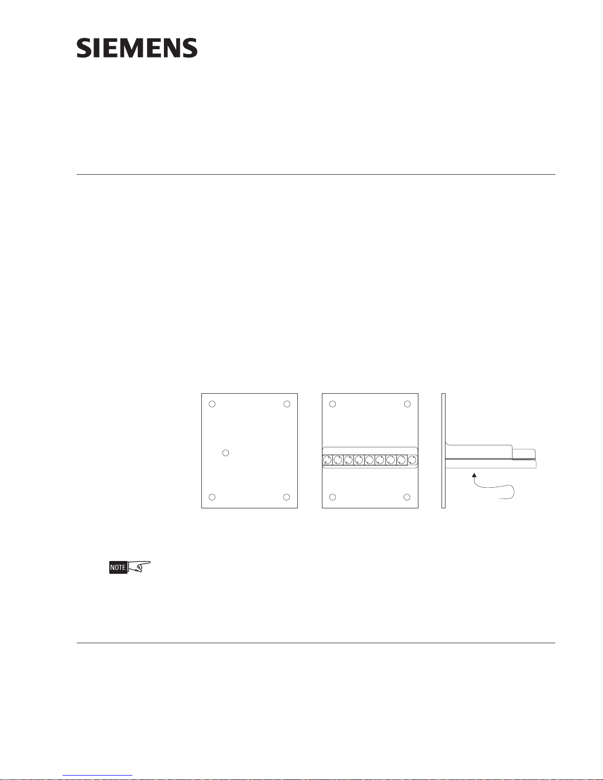
Figure 1
HZM Module
The HZM is not listed for use in mass notification applications.
Controls And Indicators The HZM has a multicolor LED, visable through the cover plate, which indicates the
condition of the circuit. This multicolor LED displays red for alarm, yellow for trouble,
and green for normal operation (See Figure 1).
PRE-INSTALLATION Setting The Module Address
P/N 315-034850-8
1. Using the DPU Device Programming Unit, plug the programming cable into
the programming points on the HZM (See Figure 1).
2. Set the address for the HZM by following the instructions in the DPU
Manual, P/N 315-033260.
Building Building
Building
Building Building
Siemens Siemens
Siemens
Siemens Siemens
TT
ecec
hnologies Dihnologies Di
T
ec
hnologies Di
TT
ecec
hnologies Dihnologies Di
IndustryIndustry
Industry
IndustryIndustry
visionvision
vision
visionvision
,,
Inc. Inc.
,
Inc.
,,
Inc. Inc.
INSTALLATION
S
2
S
Remove all system power before installation, first battery then AC. (To power up,
connect the AC first, then the battery.)
Electrical Connections After you have set the HZM address, connect the field wiring.
connections
to the HZM: initiating devices, DLC or FS-DLC device loop, and 24 VDC
power. All terminals are power limited.
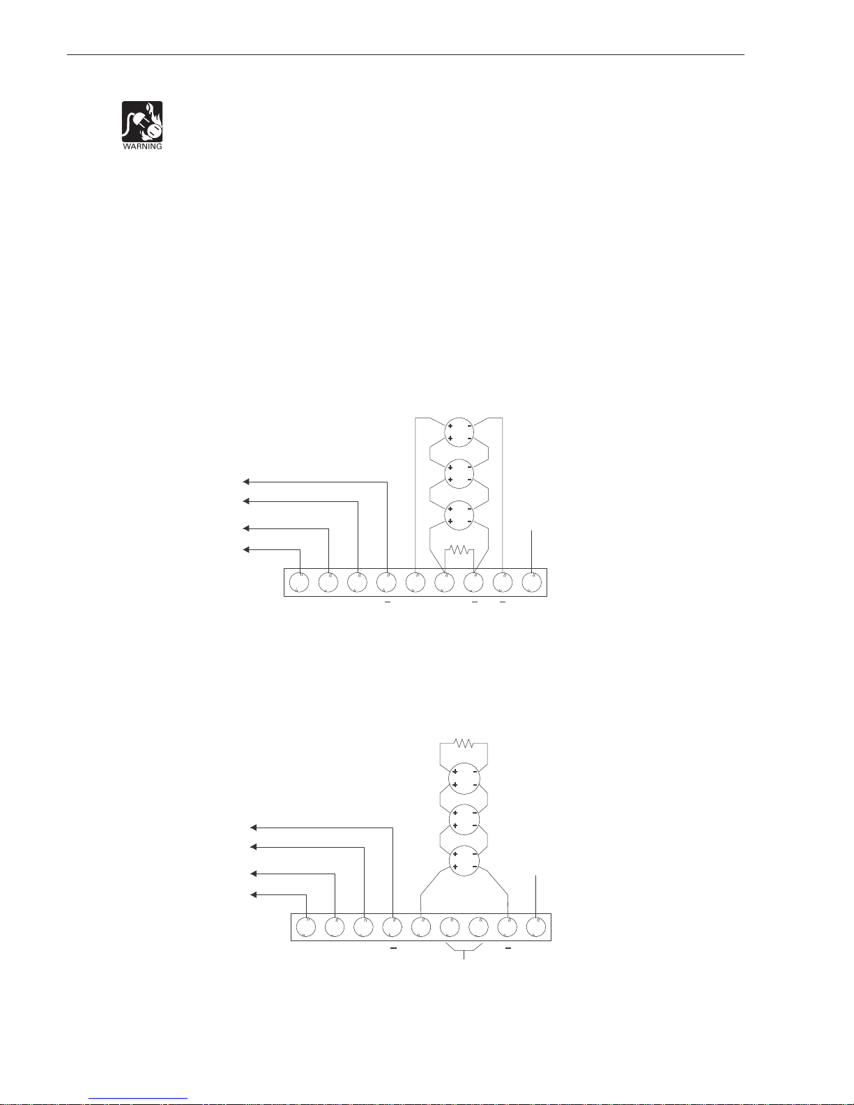
Initiating Devices (Figures 2, 3, and 4)
The HZM supports one zone of initiating devices in either Class A or Class B. The
initiating devices are connected to terminals 5–8 on the HZM terminal block. The
HZM is a polarity insensitive module and terminals 1 and 2 can be connected to
either line of the DLC or FS-DLC Device Loop. Figure 2 shows the Class A wiring.
Figure 3 shows the Class B wiring.
TYLE D/CLASS A
24VDC POWER
LINE 2
DEVICE LOOP
LINE 1
1
3
2
+++
5 6 7 8 9
4
* EOL DEVICE IS 4.7K, 1/4W (P/N 140-820188)
FOR CANADIAN APPLI CATIONS, USE MODEL †
EL-33 WITH 4.7K, 1/4W RESISTOR.
(DCLA)
EARTH
EOL * †
NOTES
1. Wire 18 AWG minimum, 12
2. Supervised, power limited to
3. Voltage 24VDC.
4. Positive and negative ground
Figure 2
HZM Initiating Devices Wiring Diagram
Class A/Style D (ULC DCLA) Installation
TYLE B/CLASS B
(DCLB)
EOL*
†
* EOL DEVICE IS 4.7K,
1/4W (P/N 140-820188)
FOR CANADIAN APPLICATIONS,†
USE MODEL EL-33 WITH
4.7K, 1/4W RESISTOR.
There are three basic
AWG maximum, 35 ohms Max.
NFPA 70 per NEC 760.
fault detected at <60K ohms
for terminals 5-8.
4VDC POWER
LINE 2
DEVICE LOOP
LINE 1
Figure 3
HZM Initiating Devices Wiring Diagram
Class B/Style B (ULC DCLB) Installation
Siemens Industry, Inc.
Building Technologies Division
EARTH
NOTES
1. Wire 18 AWG minimum, 12
1
2
3
5
4
6 7 8 9
++
NOT USED
AWG maximum, 35 ohms Max.
(both sides)
2. Supervised, power limited to
NFPA 70 per NEC 760.
3. Voltage 24VDC.
4. Positive and negative ground
fault detected at <60K ohms
for terminals 5, 8.
P/N 315-034850-82
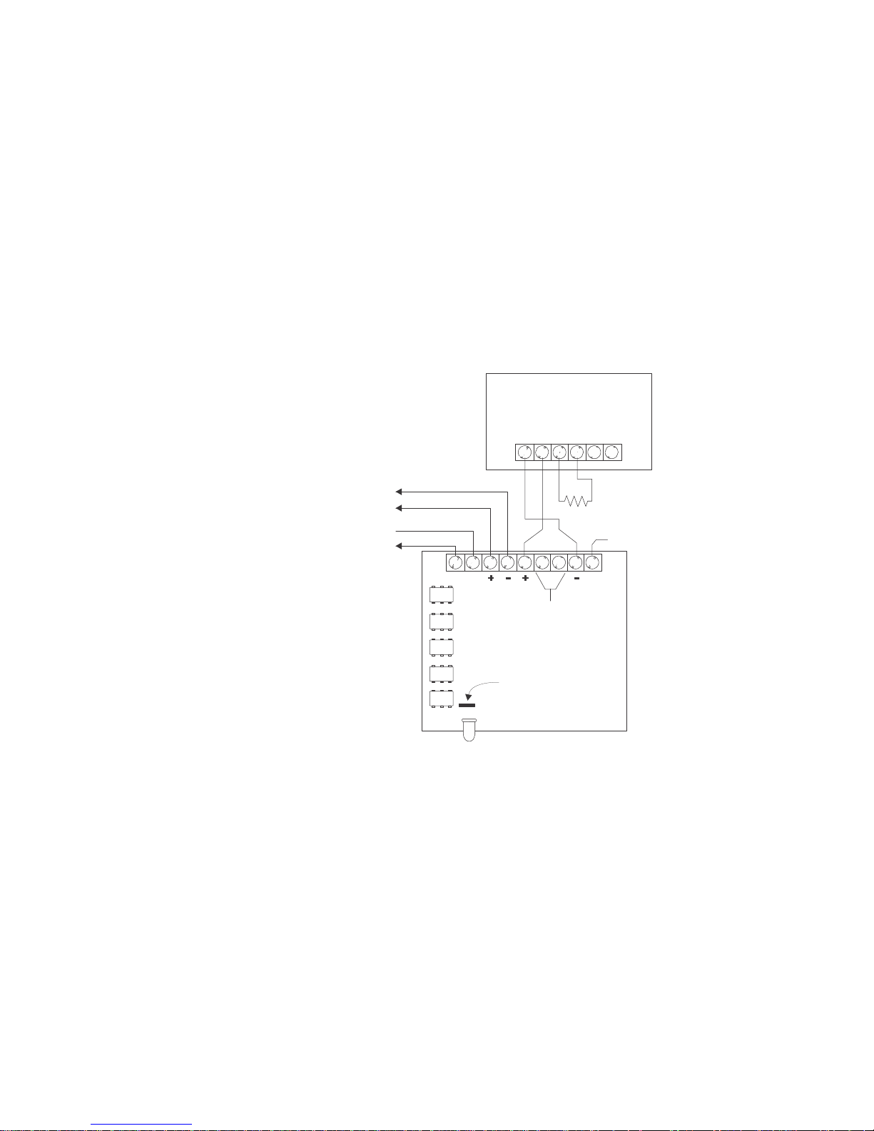
Figure 4 shows the wiring for the PB-1191 beam detector. When the PB-1191 is used,
R
D
the 2-position plug from jumper J1 must be removed.
Follow the steps listed below to remove the 2-position plug from J1:
a. Remove the screw from the center of the HZM plastic cover and place it to
one side.
b. Remove the circuit board and locate jumper J1.
c. Remove the 2-position plug from J1.
d. Reassemble the circuit board and plastic cover using the screw that was
removed in the first step.
e. Be sure to use the correct end of line device with the HZM in this configuration.
BEAM DETECTOR WIRING
CLASS B/STYLE B
(ULC DCLB)
O NOT CONNECT MORE THAN
ONE PB-1191 TO AN HZM
PB-1191
A B C D
E
F
3.6K, 1/4W
24VDC POWER
DLC DEVICE LOOP
LINE 2
LINE 1
1 2 3 4
5
6 7 8 9
NOT USED
EOL RESISTO
P/N 140-820185
EARTH
HZM
J1
NOTE:
Positive and negative ground fault detected at <60K ohms for terminals 5, 8.
Figure 4
HZM Wiring Diagram For PB-1191 Installation
Siemens Industry, Inc.
Building Technologies Division
P/N 315-034850-83
 Loading...