

Siemens HydroRanger 200 HMI Operating Instructions Manual

Ultrasonic Controllers
HydroRanger 200 HMI
Operating Instructions
08/2015Edition

Safety Guidelines: Warning notices must be observed to ensure personal safety as well as that of
others, and to protect the product and the connected equipment. These warning notices are
accompanied by a clarification of the level of caution to be observed.
Qualified Personnel: This device/system may only be set up and operated in conjunction with this
manual. Qualified personnel are only authorized to install and operate this equipment in accordance with
established safety practices and standards.
Unit Repair and Excluded Liability:
• The user is responsible for all changes and repairs made to the device by the user or the user’s
agent.
• All new components are to be provided by Siemens.
• Restrict repair to faulty components only.
• Do not reuse faulty components.
Warning: Cardboard shipping package provides limited humidity and moisture protection. This product
can only function properly and safely if it is correctly transported, stored, installed, set up, operated, and
maintained.
This product is intended for use in industrial areas. Operation of this equipment in a residential area
may cause interference to several frequency based communications.
Note: Always use product in accordance with specifications.
Copyright Siemens AG 2015. All Rights
Disclaimer of Liability
Reserved
This document is available in bound version and in
electronic version. We encourage users to purchase
authorized bound manuals, or to view electronic
versions as designed and authored by Siemens.
Siemens will not be responsible for the contents of
partial or whole reproductions of either bound or
electronic versions.
While we have verified the contents of this
manual for agreement with the
instrumentation described, variations remain
possible. Thus we cannot guarantee full
agreement. The contents of this manual are
regularly reviewed and corrections are
included in subsequent editions. We welcome
all suggestions for improvement.
Technical data subject to change.
Contact Siemens Technical Publications European Authorized Representative
at the following address:
Technical Publications
Siemens Canada Limited Siemens AG
PD PA PI LW Industry Sector
1954 Technology Drive, P.O. Box 4225 76181 Karlsruhe
Peterborough, Ontario, Canada, K9J 7B1 Deutschland
Email: techpubs.smpi@siemens.com
• For a selection of Siemens level measurement manuals, go to:
www. siemens.com/processautomation. Under Process Instrumentation, select
Measurement
• For a selection of Siemens weighing manuals, go to:
www. siemens.com/processautomation. Under Weighing Technology, select
Weighing Systems
and then go to the manual archive listed under the product family.
and then go to the manual archive listed under the product family.
Level
Continuous
© Siemens AG 2015

Table of contents
Introduction ........................................................................................................................1
The Manual ............................................................................................................................................1
Manual symbols ..........................................................................................................................1
Application examples .................................................................................................................2
Firmware revision history ...................................................................................................................2
Sensor node .................................................................................................................................2
HMI .................................................................................................................................................2
Safety notes ........................................................................................................................3
Safety marking symbols ............................................................................................................3
FCC Conformity ......................................................................................................................................4
CE Electromagnetic Compatibility (EMC) Conformity ...................................................................4
Description .........................................................................................................................7
Overview .................................................................................................................................................7
Features ..................................................................................................................................................7
Applications ............................................................................................................................................8
Approvals and certificates ..................................................................................................................8
Installing and mounting ...................................................................................................9
Mounting locations .............................................................................................................................10
Mounting instructions ..............................................................................................................11
Wall mount........................................................................................................................ 11
Cable routed through a conduit................................................................................... 12
............................................................................................................................................. 12
Cable exposed and entering through the cable glands......................................... 13
Panel mount...................................................................................................................... 14
Mounting the enclosure ................................................................................................ 15
HydroRanger 200 HMI wiring compartment .......................................................................16
Replacing the battery ...............................................................................................................17
Installing the SmartLinx®communications card ..............................................................18
Connecting .......................................................................................................................19
Terminal board ....................................................................................................................................20
Cables ....................................................................................................................................................21
Transducers .........................................................................................................................................21
Relays ....................................................................................................................................................22
Temperature sensor ...........................................................................................................................22
mA Input ................................................................................................................................................23
mA Output .............................................................................................................................................23
Level system synchronization ..........................................................................................................23
Power .....................................................................................................................................................24
Digital communications .....................................................................................................................24
RS-232 serial connection ........................................................................................................25
RS-485 serial connection ........................................................................................................25
Discrete inputs................................................................................................................. 25
Commissioning ................................................................................................................27
Local commissioning ..........................................................................................................................27
Table o f c o nten t s
i

Activating the HydroRanger 200 HMI ............................................................................................27
RUN Mode ............................................................................................................................................27
Measurement Views in RUN mode............................................................................ 28
The LCD Display ........................................................................................................................28
Measurement Mode Display: Normal operation..................................................... 28
Auxiliary Reading ............................................................................................................ 29
Multiple readings ......................................................................................................................30
Tabl e o f co n t en t s
PROGRAM Mode ................................................................................................................................31
Key functions in Measurement mode........................................................................ 31
Programming the HydroRanger 200 HMI ............................................................................31
Parameter menus............................................................................................................ 31
Quick Start Wizards ............................................................................................................................35
Setting wizards via graphical display ...................................................................................35
Application examples .........................................................................................................................58
Level application ......................................................................................................................58
Flow application ........................................................................................................................59
General operation ...........................................................................................................61
Single-point models ........................................................................................................62
Average or differential................................................................................................... 62
Dual-point models ...........................................................................................................63
Average or differential................................................................................................... 63
Measurement conditions ........................................................................................................63
Response rate.................................................................................................................. 64
Dimensions ....................................................................................................................... 64
Fail-safe indexes ............................................................................................................. 64
Relays ................................................................................................................................65
General introduction .................................................................................................................65
Relay functions ................................................................................................................ 65
Alarm.................................................................................................................................. 65
Pump................................................................................................................................... 66
Totalizing and Sampling................................................................................................. 66
Relay status – Navigation View................................................................................... 67
Relay-related parameters .......................................................................................................67
Relay wiring test.............................................................................................................. 68
Relay activation .........................................................................................................................68
Preset applications .............................................................................................................................69
Relay fail-safe ............................................................................................................................70
Security .................................................................................................................................................70
Parameter types ..................................................................................................................................70
Display readout ...................................................................................................................................71
Adjusting the Primary Reading:................................................................................... 71
Backup level override ....................................................................................................72
Backup level override parameters .................................................................................................72
Discrete inputs .................................................................................................................73
Wiring the discrete inputs ................................................................................................................73
Adjusting the discrete input logic ...................................................................................................73
mA I/O ................................................................................................................................74
ii

mA Input ...............................................................................................................................................74
mA Output .............................................................................................................................................74
Volume ..............................................................................................................................76
Readings ...............................................................................................................................................76
Vessel shape and dimensions .........................................................................................................76
Characterization chart .......................................................................................................................77
.......................................................................................................................................................78
Alarms ...............................................................................................................................79
Level .......................................................................................................................................................79
Setting simple level alarms .....................................................................................................80
Rate ........................................................................................................................................................80
In-bounds/Out-of-bounds Range ....................................................................................................80
Cable fault .............................................................................................................................................81
Temperature .........................................................................................................................................81
Loss of Echo (LOE) ..............................................................................................................................82
Pump control ....................................................................................................................83
Setting a Pump Down Group ...........................................................................................................83
Setting a Pump Up (Reservoir) Group ............................................................................................84
Other pump control algorithms ........................................................................................................86
Set relays to Alternate Duty Backup ....................................................................................86
Set relays to Fixed Duty Assist ..............................................................................................86
Set relays to Fixed Duty Backup ...........................................................................................87
Set relays to Service Ratio Duty Assist ...............................................................................87
Set relays to First In First Out .................................................................................................88
Optional pump controls .....................................................................................................................89
Starting pumps by rate of level change ...............................................................................89
Rotating pumps by service ratio ............................................................................................90
Totalizing pumped volume ......................................................................................................91
Setting independent fail-safe controls ................................................................................92
Setting a pump to Run-ON ......................................................................................................92
Setting the pump start delays ................................................................................................93
Reducing wall cling ..................................................................................................................93
Grouping pumps ........................................................................................................................94
Setting a flush valve ................................................................................................................94
Relay controlled by communications ...................................................................................95
Tracking pump usage ........................................................................................................................95
Rake (Screen) control ....................................................................................................96
Setting a rake control ........................................................................................................................96
Setting common parameters ..................................................................................................97
Set Relay 1 (Operate Rake) .....................................................................................................97
Set Relays 2 to 4 (Level Alarms) ............................................................................................97
External totalizers and flow samplers ........................................................................98
Relay contacts .....................................................................................................................................98
Totalizer .................................................................................................................................................98
Flow sampler ........................................................................................................................................99
Based on volume and time .....................................................................................................99
Open Channel Monitoring (OCM) ...............................................................................100
Common parameters .......................................................................................................................100
Table o f c o nten t s
iii

Setting Zero Head ...................................................................................................................101
Setting totalized volume ..................................................................................................................103
Applications supported by HydroRanger 200 HMI ...................................................................103
BS-3680 / ISO 1438/1 Thin Plate V-Notch weir...................................................... 103
BS-3680 / ISO 4359 Rectangular Flume................................................................... 104
Palmer-Bowlus Flume................................................................................................. 105
H-Flume........................................................................................................................... 106
Tabl e o f co n t en t s
PMDs with exponential flow to Head Function .........................................................................107
Applicable weir profiles .........................................................................................................107
Non-applicable weir profiles ................................................................................................108
Parshall Flume .........................................................................................................................109
Leopold Lagco Flume .............................................................................................................110
Cut Throat Flume .....................................................................................................................111
Universal calculation support ........................................................................................................112
Typical flow characterization ...............................................................................................112
Example flumes .......................................................................................................................113
Example weirs ..........................................................................................................................113
Configuration testing ....................................................................................................115
I/O Checkout .......................................................................................................................................115
Application test ..................................................................................................................................115
Parameters .....................................................................................................................117
Key terms ............................................................................................................................................117
Parameter indexing ..........................................................................................................................118
Index selector examples .................................................................................................................119
Sensor and measurement.......................................................................................... 119
Calibration...................................................................................................................... 120
Pumps.............................................................................................................................. 120
High level alarm............................................................................................................ 120
Index types .........................................................................................................................................121
Alphabetical list .................................................................................................................................206
Service and maintenance ............................................................................................215
Firmware updates .............................................................................................................................215
Decontamination declaration ........................................................................................................215
Troubleshooting ............................................................................................................217
Communication troubleshooting ...................................................................................................217
General fault codes ..........................................................................................................................218
Common problems chart .................................................................................................................219
Noise problems .................................................................................................................................226
Determine the noise source .................................................................................................226
Non-transducer noise sources ............................................................................................227
Avoiding common wiring problems ....................................................................................227
Reducing electrical noise ......................................................................................................227
Reducing acoustical noise ....................................................................................................227
Measurement difficulties ................................................................................................................228
Loss of Echo (LOE) ..................................................................................................................228
Adjust transducer aiming........................................................................................... 228
Increase fail-safe timer value ................................................................................... 228
Install a transducer with a narrower beam........................................................... 228
Fixed reading ......................................................................................................................................229
iv

Obstructions in the sound beam .........................................................................................229
Nozzle mountings ....................................................................................................................229
Set the HydroRanger 200 HMI to ignore the bad echo ..................................................229
Wrong reading ...................................................................................................................................230
Types of wrong readings ......................................................................................................230
Liquid splashing .......................................................................................................................230
Adjust the Echo Algorithm ....................................................................................................230
Transducer ringing ...........................................................................................................................230
Unit repair and excluded liability ...................................................................................................231
Technical data ...............................................................................................................233
Appendix A: Technical reference ..............................................................................239
Transmit pulse ...................................................................................................................................239
Echo processing ................................................................................................................................239
TVT (Time Varying Threshold) curves ..........................................................................................240
Auto False Echo Suppression ..............................................................................................240
Algorithm........................................................................................................................ 241
Distance calculation .........................................................................................................................241
Sound Velocity ...................................................................................................................................242
Scanning .............................................................................................................................................243
Volume calculation ...........................................................................................................................243
Universal Curved .....................................................................................................................244
Flow calculation ................................................................................................................................244
Universal Linear .......................................................................................................................245
Universal Curved .....................................................................................................................245
Response Rate ...................................................................................................................................246
Analog Output ....................................................................................................................................246
Current Output Function ........................................................................................................246
Loss of Echo (LOE) ..................................................................................................................247
Fail-safe Mode.............................................................................................................. 247
Appendix B: Pump control reference ........................................................................248
Pump control options .......................................................................................................................248
Pump groups ............................................................................................................................248
Pump by rate ............................................................................................................................248
Pump control algorithms .................................................................................................................248
Fixed Duty Assist .....................................................................................................................249
Fixed Duty Backup ..................................................................................................................249
Alternate Duty Assist .............................................................................................................250
Alternate Duty Backup ..........................................................................................................250
Service Ratio Duty Assist .....................................................................................................251
Service Ratio Duty Backup ...................................................................................................252
First In First Out ........................................................................................................................252
Pump by Rate ...........................................................................................................................252
Other pump controls .........................................................................................................................252
Appendix C: Communications .....................................................................................253
HydroRanger 200 HMI communication systems .......................................................................253
Optional SmartLinx®Cards ............................................................................................................253
Communication systems .................................................................................................................253
Communication ports .......................................................................................................................254
Modbus ......................................................................................................................................254
Table o f c o nten t s
v

SmartLinx® ........................................................................................................................................254
Communications installation ......................................................................................255
Wiring guidelines ..............................................................................................................................255
Configuring communications ports (parameters) .....................................................................257
SIMATIC Process Device Manager (PDM) ..............................................................258
Device description ..................................................................................................................258
Modbus register map ...................................................................................................259
Tabl e o f co n t en t s
Word order (R40,062) .......................................................................................................................260
Map ID (R40,063) ...............................................................................................................................260
Product ID (R40,064) .........................................................................................................................261
Point data (R41,010 – R41,031) .......................................................................................................261
Totalizer (R41,040 – R41,043) ..........................................................................................................261
Input/Output (R41,070 – R41,143) ...................................................................................................261
Discrete inputs (R41,070) .......................................................................................................262
Relay outputs (R41,080) ..........................................................................................................262
mA Input (R41,090) ..................................................................................................................262
mA Output (R41,110-41,111) ..................................................................................................262
Pump control (R41,400 – R41,474) ........................................................................................262
Pump ON setpoint (R41,420 – R41,425) ...............................................................................262
Pump OFF setpoint (R41,430 – R41,435) .............................................................................262
Pumped volume (R41,440 – R41,443) ..................................................................................263
Pump hours (R41,450 – R41,461) ..........................................................................................263
Pump starts (R41,470 – R41,475) ..........................................................................................263
Parameter access (R43,998 – R46,999) ..............................................................................263
Parameter indexing ................................................................................................................264
Indexing the parameter access area ...................................................................... 264
Reading parameters ...............................................................................................................264
Global index method.................................................................................................... 264
Parameter-specific index method............................................................................ 265
Writing parameters ................................................................................................................265
Global index method.................................................................................................... 266
Parameter-specific index method............................................................................ 266
Format words (R46,000 to R46,999) ...............................................................................................266
Global index method.................................................................................................... 266
Parameter-specific index method............................................................................ 266
Format registers ......................................................................................................................266
Data types .......................................................................................................................268
Numeric values .................................................................................................................................268
Bit values ............................................................................................................................................268
Unsigned double precision integer (UINT32) .............................................................................268
Split values .........................................................................................................................................269
Text messages ...................................................................................................................................270
Relay function codes (
2.8.1.4. Relay Function
Only) .................................................................271
Error handling ................................................................................................................272
Modbus responses ...........................................................................................................................272
Error handling ....................................................................................................................................272
Communication troubleshooting ................................................................................273
General ................................................................................................................................................273
vi

Specific ................................................................................................................................................273
Single Parameter Access (SPA) .................................................................................274
Mapping ..............................................................................................................................................274
Reading parameters .........................................................................................................................274
Writing parameters ..........................................................................................................................275
Format register ..................................................................................................................................275
Error codes .........................................................................................................................................276
Appendix D: Updating software .................................................................................277
Appendix E: Upgrading .................................................................................................278
Mounting a HydroRanger 200 HMI .....................................................................................278
Connecting the transducer ...................................................................................................278
Co-axial transducer extension.................................................................................. 278
Connecting a transducer with RG62 co-axial extension cable......................... 279
Appendix F: Conduit Entry for Class I, Div 2 Applications .....................................280
Programming chart .......................................................................................................283
LCD Menu Structure .....................................................................................................292
Index ................................................................................................................................299
Table o f c o nten t s
vii

Tabl e o f co n t en t s
viii

Introduction
The HydroRanger 200 HMI (Human Machine Interface) ultrasonic level controller is
intended for use in industrial areas. Operation of this equipment in a residential area may
cause interference to several frequency based communications.
Please follow the installation and operating procedures for a quick, trouble-free installation
and to ensure the maximum accuracy and reliability of your HydroRanger 200 HMI.
The Manual
This manual applies to the HydroRanger 200 HMI series only. It provides information to help
set up your device for optimum performance, including:
• How to program the device
• Example applications
• Principles of operation
• Parameter values
• Parameter uses
1.
Modbus is a registered trademark of Schneider Electric.
We always welcome suggestions and comments about manual content, design, and
accessibility. Please direct your comments to techpubs.smpi@siemens.com.
For other Siemens level measurement manuals, go to:
www.siemens.com/level
, and look under Level Measurement.
Manual symbols
Please note their use carefully.
Alternating Current
Direct Current
Earth (ground) Terminal
• Outline diagrams
• Wiring diagrams
• Installation requirements
•Modbus®
• Modem configuration
1
register mapping
HydroRanger 200 HMI
Protective Conductor Terminal
Caution (refer to instructions)
Service port
A5E36281317 HydroRanger 200 HMI – OPERATING INSTRUCTIONS Page 1
Application examples
The application examples used in this manual illustrate the versatility of the HydroRanger
200 HMI. There is often a number of different ways to approach an application, therefore
varying configurations may apply.
In all examples, substitute your own application details. If the examples are not suitable
to your application, check the relevant parameter references for other available options.
Firmware revision history
This history establishes the correlation between the current documentation and the valid
firmware of the device.
Sensor node
Firmware
Rev.
2.00.00 1.13.02 October 1, 2015 Initial release.
HydroRanger 200 HMI
PDM
EDD Rev.
Date Changes
HMI
Firmware
Rev.
2.00.00 October 1, 2015 Initial release.
Date Changes
Page 2 HydroRanger 200 HMI – OPERATING INSTRUCTIONS A5E36281317
Safety notes
Special attention must be paid to warnings and notes highlighted from the rest of the text
by grey boxes.
1
WARNING: Relates to a caution symbol on the product, and means
that failure to observe the necessary precautions can result in
death, serious injury, and/or considerable material damage.
WARNING
1
: Means that failure to observe the necessary
precautions can result in death, serious injury, and/or considerable
material damage.
Note:
means important information about the product or that part of the operating
manual.
Safety marking symbols
In manual On product Description
Earth (ground) Terminal (shield)
Protective Conductor Terminal
Dispose of in an environmentally safe manner, and
according to local regulations.
Safety notes
WARNING: refer to accompanying documents (manual)
for details.
CAUTION: Observe electrostatic discharge precautions
prior to handling electronic components within the
wiring compartment.
1.
This symbol is used when there is no corresponding caution symbol on the product.
A5E36281317 HydroRanger 200 HMI – OPERATING INSTRUCTIONS Page 3

FCC Conformity
US Installations only: Federal Communications Commission (FCC) rules
WARNING: Changes or modifications not expressly approved by
Siemens could void the user’s authority to operate the equipment.
Notes:
• This equipment has been tested and found to comply with the limits for a Class A
digital device, pursuant to Part 15 of the FCC Rules. These limits are designed to
provide reasonable protection against harmful interference when the equipment is
operated in a commercial environment.
• This equipment generates, uses, and can radiate radio frequency energy and, if not
installed and used in accordance with the instruction manual, may cause harmful
interference to radio communications. Operation of this equipment in a residential
area is likely to cause harmful interference to radio communications, in which case
the user will be required to correct the interference at his own expense.
• FCC Compliance for DC version applies to battery powered operation.
CE Electromagnetic Compatibility (EMC) Conformity
This equipment has been tested and found to comply with the following EMC Standards:
EMC Standard Title
Limits and methods of measurements of radio
Safety notes
CISPR 11: 2009/EN 55011: 2009, Class A
EN 61326-1:2013
IEC 61326-1:2012
EN61000-3-2: 2006
EN61000-3-3: 2008
A1: 2001 + A2: 2005
EN61000-4-2:2009
EN61000-4-3:2006
EN61000-4-4:2004
disturbance characteristics of industrial, scientific,
and medical (ISM) radio-frequency equipment.
Electrical Equipment for Measurement, Control and
Laboratory Use – Electromagnetic Compatibility.
Electromagnetic Compatibility (EMC) Part 3-2: Limits
for harmonic current emissions (equipment input
current
≤ 16A per phase).
Electromagnetic Compatibility (EMC) Part 3-3:
Limitation of voltage changes, voltage fluctuations,
and flicker in public low voltage supply systems, for
equipment with rated current
not subject to conditional connection.
Electromagnetic Compatibility (EMC) Part 4-2:Testing
and measurement techniques – Electrostatic
discharge immunity test.
Electromagnetic Compatibility (EMC) Part 4-3:
Testing and measurement techniques – Radiated,
radio-frequency, electromagnetic field immunity test.
Electromagnetic Compatibility (EMC) Part 4-4:
Testing and measurement techniques – Electrical
fast transient/burst immunity test.
≤ 16A per phase and
Page 4 HydroRanger 200 HMI – OPERATING INSTRUCTIONS A5E36281317

EMC Standard Title
Electromagnetic Compatibility (EMC) Part 4-5:
EN61000-4-5:2006
EN61000-4-6:2009
EN61000-4-8:2010
EN61000-4-11: 2004
Testing and measurement techniques – Surge
immunity test.
Electromagnetic Compatibility (EMC) Part 4-6:
Testing and measurement techniques – Immunity to
conducted disturbances, induced by radio-frequency
fields.
Electromagnetic Compatibility (EMC) Part 4-8:
Testing and measurement techniques – Power
frequency magnetic field immunity test.
Electromagnetic Compatibility (EMC) Part 4-11:
Testing and measurement techniques - voltage clips,
short interruptions and voltage variations immunity
tests.
Safety notes
A5E36281317 HydroRanger 200 HMI – OPERATING INSTRUCTIONS Page 5

Safety notes
Page 6 HydroRanger 200 HMI – OPERATING INSTRUCTIONS A5E36281317

Description
Overview
The HydroRanger 200 HMI (Human Machine Interface) is a six-relay ultrasonic controller
for Level and Volume measurements, available in single- or dual-point models. It has
Open Channel Monitoring capabilities, a large number of advanced pump control
algorithms, and is equipped with digital communications.
The HydroRanger 200 HMI features menu-driven programming and a host of wizards for
plug and play performance, accessed through its four-button navigation panel with
backlit graphical display.
Features
• Easy to use interface with local push-button programming.
• Menu-driven parameters and wizard support for key applications.
• Level, Volume, and Open Channel Flow measurements.
• Six relays combined with a suite of pump, alarm, and relay control features.
• SIMATIC PDM connects directly to the device using Modbus.
• Two discrete inputs for backup level override.
• Communication using built-in Modbus RTU via RS-485.
• Compatible with SmartLinx®communications systems for PROFIBUS DPV0,
PROFIBUS DPV1, and DeviceNet.
• Auto False Echo Suppression for fixed obstruction avoidance.
A5E36281317 HydroRanger 200 HMI – OPERATING INSTRUCTIONS Page 7
Description
Applications
• Liquids, solids and slurry monitoring in small to large process and storage vessels or
outdoor applications (open air).
• Fuel oil, municipal waste, acids, woodchips or on materials with high angles of
repose.
• Key sample applications include: wet wells, flumes/weirs, bar screen control,
hoppers, chemical storage, liquid storage, crusher bins, and dry solids storage.
Approvals and certificates
The HydroRanger 200 HMI is available with General Purpose and Hazardous Area
approvals. For details, see the chart below.
Note: The device nameplate lists the approvals that apply to your device.
Application
type
Non-hazardous General Purpose CSA
Hazardous Non-incendive
HydroRanger
200 HMI
approval
version
Approval rating Valid for
, CE, FM, UL, RCM
US/C
CSA Class I, Div. 2, Groups A, B, C, D; Class II,
Div 2, Groups F, G; Class III
N. America,
Europe,
Australia
Canada
Description
Page 8 HydroRanger 200 HMI – OPERATING INSTRUCTIONS A5E36281317

Installing and mounting
Installing
Notes:
• Installation must only be performed by qualified personnel, and in accordance
with local governing regulations.
• This product is susceptible to electrostatic shock. Follow proper grounding
procedures.
All field wiring must have insulation suitable for at least 250V.
Hazardous voltages present on transducer terminals during
operation.
DC input terminals shall be supplied from a source providing
electrical isolation between the input and output, in order to
meet applicable safety requirements of IEC 61010-1 (e.g. Class 2
or Limited Energy Source).
CAUTION: Observe electrostatic discharge precautions prior to
handling electronic components within the wiring compartment.
• Relay contact terminals are for use with equipment that has no accessible live
parts and wiring that has insulation suitable for at least 250 V. The maximum
allowable working voltage between adjacent relay contacts shall be 250 V.
• The non-metallic enclosure does not provide grounding between conduit
connections. Use grounding type bushings and jumpers.
• Before opening the lid, ensure that the inside of the enclosure will not be
contaminated with liquids or dust from the local environment.
• Ensure power is removed from the HydroRanger 200 HMI before servicing.
Follow all local electrical safety codes and guidelines.
• Ensure power is removed from the HydroRanger 200 HMI before disconnecting
or connecting the HMI.
• The HydroRanger 200 HMI electronics must only be installed in the vented
enclosure which accompanies the product.
• The equipment must be protected by a 15 A fuse or circuit breaker on all currentcarrying conductors in the building installation.
A5E36281317 HydroRanger 200 HMI – OPERATING INSTRUCTIONS Page 9
Installing and mounting

Mounting locations
Recommended
• Ambient temperature is always within -20 to 50 °C (-5 to 122 °F).
• The HydroRanger 200 HMI display window is at shoulder level, unless most
interactions are through a SCADA system.
• Clear access to the device, in order to have easy reach of the local push buttons or
to swing the unit lid open unobstructed.
• Cable length requirements are minimal.
• Mounting surface is free from vibration.
Avoid
• Exposure to direct sunlight. (Provide a sun shield to avoid direct sunlight.)
• Close proximity to high voltage/current runs, contacts, SCR or variable frequency
motor speed controllers.
Note: Recommended maximum torque for lid screws not to exceed 0.9 Nm (8 in-
lbs.).
Installing and mounting
Page 10 HydroRanger 200 HMI – OPERATING INSTRUCTIONS A5E36281317
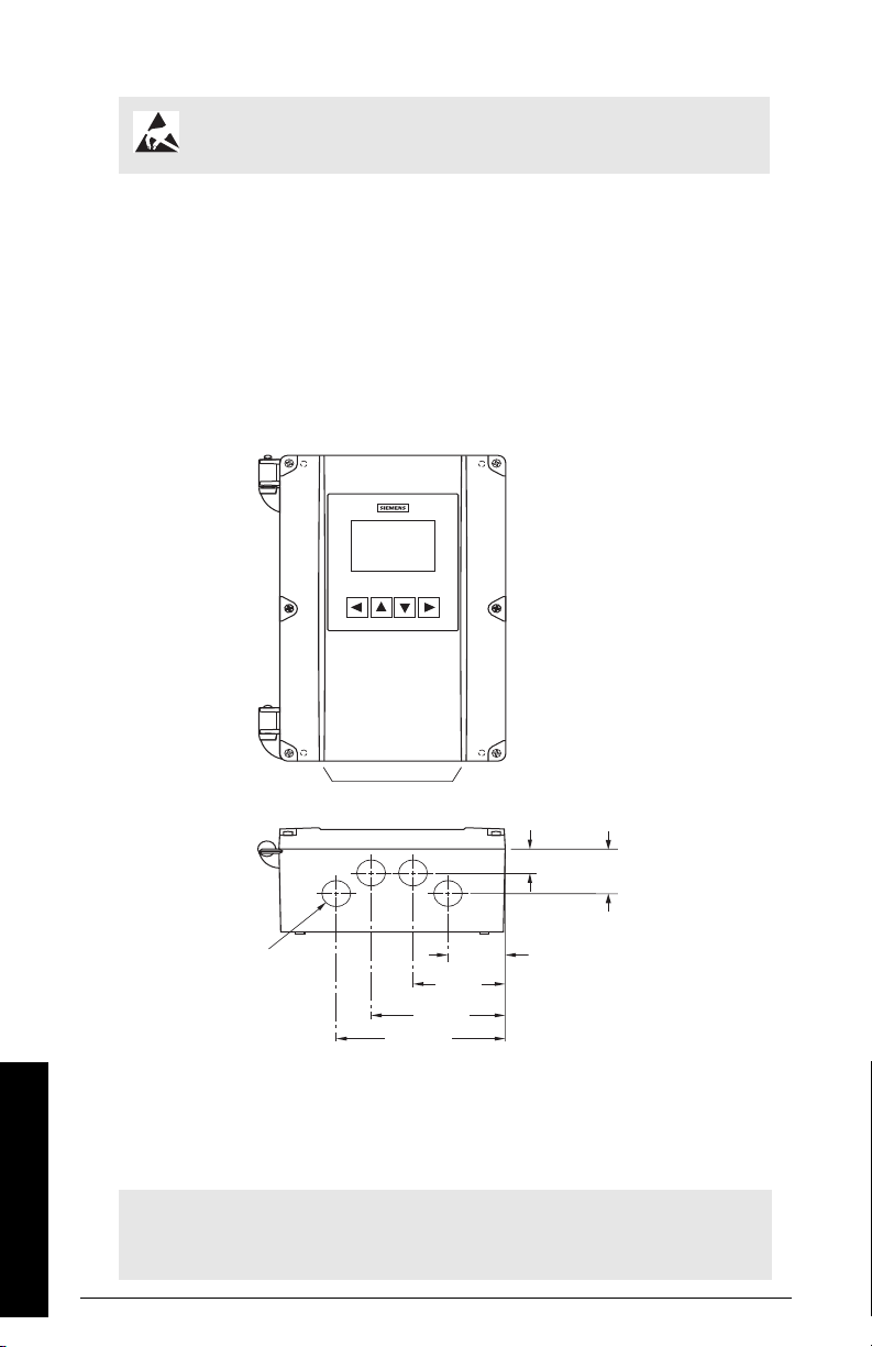
Mounting instructions
15 mm
(0.6")
15 mm
(0.6")
131 mm
(5.2")
161 mm
(6.3")
4.3 mm dia.
(0.17") four
mounting
holes
Lid screws
(6)
87 mm
(3.4")
6 mm
(0.2")
240 mm
(9.4")
228 mm
(9.0")
Enclosure lid
Cable entry
location
Enclosure
base
Cable entry
Mounting screw holes
Note: When routing cable through a conduit, please follow the instructions on
page 12 before mounting the HydroRanger 200 HMI.
Wall mount
Enclosure dimensions
Mounting the enclosure
1. Remove the lid screws and open the lid to reveal the mounting screw holes.
2. Mark and drill four
holes in the mounting surface for the four screws
(customer supplied).
3. Fasten with a long screwdriver.
Please note:
• Recommended mounting: directly to wall or to
electrical cabinet back panel.
• Recommended mounting screws: #6.
• If alternate mounting surface is used, it MUST be able
to support four times the weight of the unit.
A5E36281317 HydroRanger 200 HMI – OPERATING INSTRUCTIONS Page 11
Installing and mounting
Cable routed through a conduit
19 mm (0.75")
35 mm
(1.4")
41 mm
(1.6")
65 mm
(2.6")
95 mm
(3.7")
120 mm
(4.7")
Suitable location for conduit entries. See recommended pattern below.
Drill for M20-size
conduit holes.
CAUTION: Observe electrostatic discharge precautions prior to handling
electronic components within the wiring compartment.
1. Disconnect the Display cable by pressing the locking tab and pulling it straight out.
2. Remove the four mounting screws holding the plastic cover and motherboard to the
enclosure.
3. Remove the plastic cover by pulling it straight out. Be careful not to damage the
motherboard and other electronic components with static electricity.
4. Remove the motherboard from the enclosure by pulling the board straight out. Be
careful not to damage the electronics with static electricity.
5. Drill the required cable entry holes. Make sure conduit holes do not interfere with
the lower areas on the terminal block, circuit board, or SmartLinx®card. Please see
the illustration below.
6. Attach the conduit to the hub before connecting the hub to the enclosure, using only
approved suitable-sized hubs for watertight applications.
7. Reinstall the motherboard and plastic cover; secure them with the mounting screws.
8. Reconnect the Display cable.
Note: For conduit locations and assembly for hazardous mounting in Class I, Div 2
applications, please see Drawing A5E35806240A in
Class I, Div 2 Applications
Installing and mounting
Page 12 HydroRanger 200 HMI – OPERATING INSTRUCTIONS A5E36281317
on page 273.
Appendix F: Conduit Entry for

Cable exposed and entering through the cable glands
1. Unscrew the glands and attach them loosely to the enclosure.
2. Thread the cables through the glands. To avoid interference, ensure that the power
cable is kept separated from the signal cables, and then wire the cables to the
terminal blocks.
3. Tighten the glands to form a good seal.
Note: Where more holes are required than are supplied in the enclosure, follow
the instructions on
Cable routed through a conduit
on page 12.
A5E36281317 HydroRanger 200 HMI – OPERATING INSTRUCTIONS Page 13
Installing and mounting
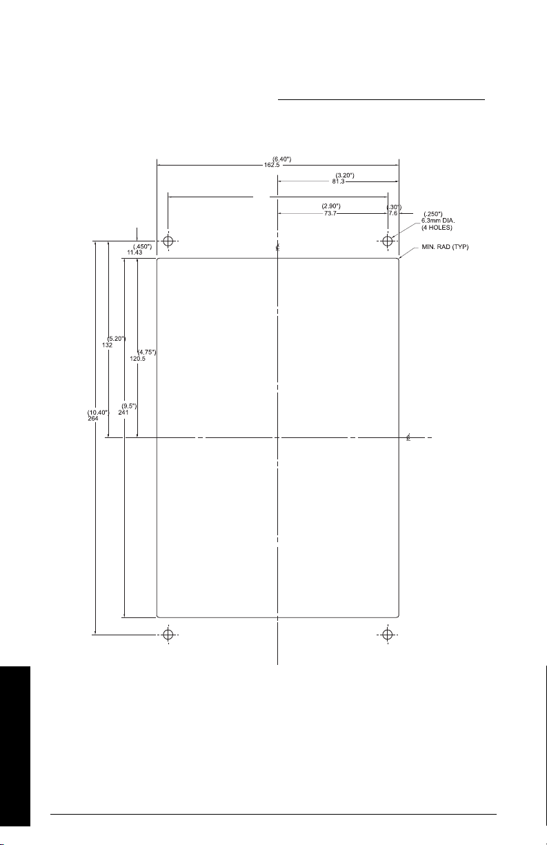
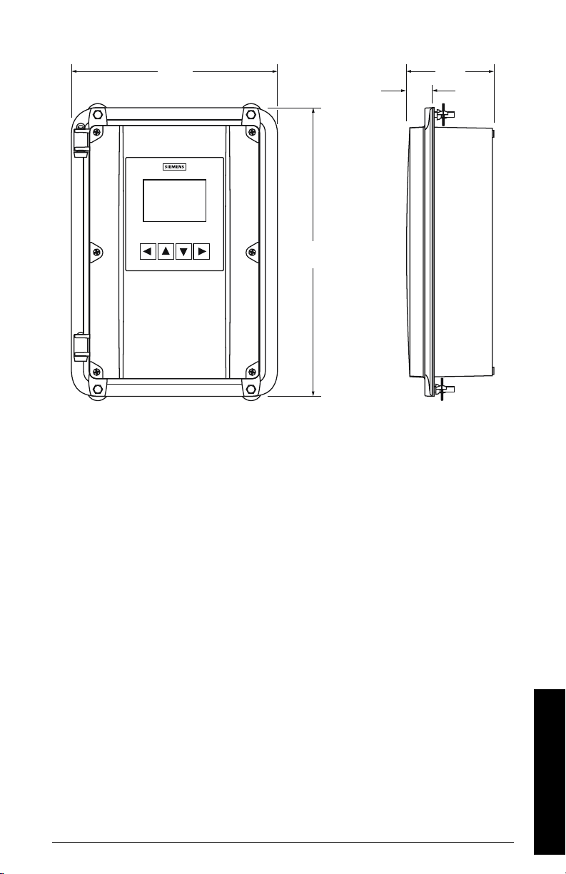
Panel mount
Installing the panel mount unit requires making a cutout in the panel. The dimensions for
the cutout are provided in the illustration below. A full size cutout template is provided
with your unit or may be downloaded from www.siemens.com/processinstrumentation
Cutout dimensions
.
Cutout instructions
1. Select a place for the unit and fasten the template onto the panel (use tape or
tacks).
2. Drill the four fastener holes.
3. Make the cutout using the appropriate tools.
4. Mount unit according to the instructions on page 15.
Installing and mounting
Page 14 HydroRanger 200 HMI – OPERATING INSTRUCTIONS A5E36281317
Panel mount dimensions
198 mm
(7.8")
278 mm
(10.9")
(1.2")
94 mm
(3.7")
31 mm
Mounting the enclosure
Once cutout is complete and mounting holes are drilled, follow these steps:
1. Remove the lid from the device by undoing its six lid screws and lifting it off its
hinges.
2. Disconnect the display cable by pressing the locking tab and pulling straight out.
3. Remove the four screws holding the plastic cover and motherboard to the
enclosure.
4. Remove the plastic cover by pulling it straight out. Be careful not to damage the
motherboard electronics with static electricity.
5. Remove the motherboard from the enclosure by pulling the board straight out. Be
careful not to damage the electronics with static electricity.
6. Drill the required cable entry holes. Be sure to compensate for panel door
dimensions and make sure conduit holes do not interfere with the lower areas on
the terminal block, circuit board, or SmartLinx®card.
7. Reinstall the motherboard and plastic cover; secure them with the mounting screws.
8. Reconnect the display cable.
9. Place the unit into the panel and insert hexagonal fasteners through bevel slots and
pre-drilled panel holes.
10. Fasten with wingnuts and hand tighten.
11. Add conduit or glands and wire as required.
Helpful hint: Use tape to hold the hexagonal heads in slots while attaching the wingnuts.
A5E36281317 HydroRanger 200 HMI – OPERATING INSTRUCTIONS Page 15
Installing and mounting
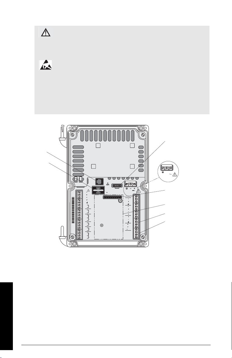
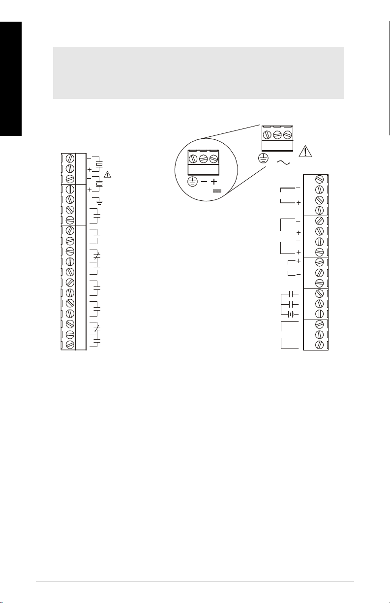
HydroRanger 200 HMI wiring compartment
12 - 30 V
OPTIONALCARD
INPUT POWER
DISPLAY
BATTERY
SERVICE
20
29
21
30
25
34
22
31
26
35
23
32
27
36
24
33
28
COM
DISCRETE
INPUTS
A
RS485
TS-3
B
SYNC
mA
INPUT
mA
OUTPUT
2
1
SHLD
SHLD
1
2
DC
1
2
2
1
3
4
5
6
7
8
9
10
11
12
16
13
17
14
18
15
19
TRANSDUCER
RLY 1
RLY 2
RLY 3
RLY 4
RLY 5
RLY 6
WHT
WHT
BLK
BLK
SHLD
OR
100 - 230V
L2/N L1
INPUT POWER
Battery
Power supply
Female connector
for SmartLinx®
Card
SmartLinx®
card (optional)
Terminals
RS-485
connecti ons
RS-232 RJ-11
Connector
Display cable port
WARNING: Check the device label on your instrument to verify
the approval rating.
Use appropriate conduit seals to maintain applicable IP and
NEMA ratings.
CAUTION: Ensure the terminal strips are terminated to the correct
location during re-installation. Failure to do so may result in
damage to the device or the external equipment that is attached.
Notes:
• Terminal strips can be removed to improve ease of wiring.
• Separate cables and conduits may be required to conform to standard
instrumentation wiring practices or electrical codes.
Installing and mounting
Page 16 HydroRanger 200 HMI – OPERATING INSTRUCTIONS A5E36281317
Replacing the battery
Battery
+
The HydroRanger 200 HMI comes pre-installed with a battery to power the RAM that
stores parameter settings and totalizer values in between hourly backups to non-volatile
memory. It is important to always have a working battery installed in the device to ensure
that settings and values are not lost.
WARNING: Disconnect power before replacing the battery.
Notes on the battery:
• Number: BR2032
• Life expectancy: 10 years
• Type: Lithium metal coin cell
Dispose of battery in an environmentally safe manner, and according to
local regulations.
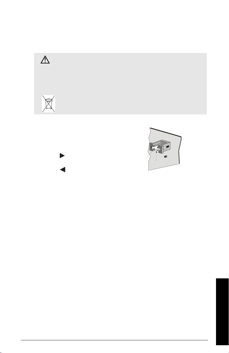
Installing a replacement battery
1. To ensure that the most recent data is
written to non-volatile memory, use the local
push buttons to enter Program mode by
pressing .
2. Return to Measurement mode by
pressing .
3. Disconnect power to the device.
4. Open the enclosure lid.
5. Slide the old battery out of the holder.
6. Slide the new battery into the battery holder. Make sure it is positioned in the
correct polarity in accordance to the label.
7. Close and secure the enclosure lid.
A5E36281317 HydroRanger 200 HMI – OPERATING INSTRUCTIONS Page 17
Installing and mounting

Installing the SmartLinx®communications card
12 - 30 V
OPTIONAL CARD
INPUT POWER
DISPLAY
BATTERY
SERVICE
20
29
21
30
25
34
22
31
26
35
23
32
27
36
24
33
28
COM
DISCRETE
INPUTS
A
RS485
TS-3
B
SYNC
mA
INPUT
mA
OUTPUT
2
1
SHLD
SHLD
1
2
DC
1
2
2
1
3
4
5
6
7
8
9
10
11
12
16
13
17
14
18
15
19
TRANSDUCER
RLY 1
RLY 2
RLY 3
RLY 4
RLY 5
RLY 6
WHT
WHT
BLK
BLK
SHLD
SmartLinx®communications cards are generally pre-installed. If unit does not have a
SmartLinx®card, follow these steps to install one:
1. Disconnect power to the device.
2. Align card with the two mounting posts and then press-fit with the female connector.
3. Use the screws supplied with the card to attach it to the mounting posts.
4. Wire in the SmartLinx®card according to SmartLinx®manual.
WARNING: Disconnect power before installing the
communication card.
Note:
For EMC compliance, it is necessary to install the provided clamp-on ferrite
to the communications cable, at the connection point to the SmartLinx®card.
Installing and mounting
Page 18 HydroRanger 200 HMI – OPERATING INSTRUCTIONS A5E36281317

Connecting
Siemens transducer(s)
Laptop
Customer alarm,
pump, or control
device
Siemens TS-3
temperature sensor
Customer device,
digital output
Customer device,
analog output
Customer network or
modem
SmartLinx® Card
Display, PLC, chart
recorder, or other
control device
HydroRanger 200
HMI
Safety notes for connection
• Verify that all system components are installed in accordance with instructions.
• Connect all cable shields to the HydroRanger 200 HMI shield terminals to avoid
differential ground potentials.
• Keep exposed conductors on shielded cables as short as possible to reduce noise
on the line caused by stray transmissions and noise pickup.
Connecting
A5E36281317 HydroRanger 200 HMI – OPERATING INSTRUCTIONS Page 19
Terminal board
L2/N L1
TB1
TB3
TB2
2
1
SHIELD
SYNC
OUTPUTS
INPUTS
B
A
COM
TB1
DC version
OR
Note: Recommended torque on terminal clamping screws.
• 0.56 - 0.79 Nm
• 5 - 7 in.lbs
Please do not overtighten the screws.
Connecting
12-30 V
RELAY 1
RELAY 2
RELAY 3
RELAY 4
RELAY 5
RELAY 6
DISCRETE
mA INPUT
4 - 20 mA
TS-3
SHIELD
RS485
1
2
1
2
Page 20 HydroRanger 200 HMI – OPERATING INSTRUCTIONS A5E36281317
 Loading...