

Siemens HydroRanger 200 Instruction Manual
Instruction Manual July 2009
hydroranger
200

Safety Guidelines: Warning notices must be observed to ensure personal safety as well as that of
others, and to protect the product and the connected equipment. These warning notices are
accompanied by a clarification of the level of caution to be observed.
Qualified Personnel: This device/system may only be set up and operated in conjunction with this
manual. Qualified personnel are only authorized to install and operate this equipment in accordance with
established safety practices and standards.
Unit Repair and Excluded Liability:
• The user is responsible for all changes and repairs made to the device by the user or the user’s
agent.
• All new components are to be provided by Siemens Milltronics Process Instruments Inc.
• Restrict repair to faulty components only.
• Do not reuse faulty components.
Warning: Cardboard shipping package provides limited humidity and moisture protection. This product
can only function properly and safely if it is correctly transported, stored, installed, set up, operated, and
maintained.
This product is intended for use in industrial areas. Operation of this equipment in a residential area
may cause interference to several frequency based communications.
Note: Always use product in accordance with specifications.
Copyright Siemens Milltronics Process
Disclaimer of Liability
Instruments Inc. 2009. All Rights Reserved
This document is available in bound version and in
electronic version. We encourage users to purchase
authorized bound manuals, or to view electronic versions
as designed and authored by Siemens Milltronics Process
Instruments Inc. Siemens Milltronics Process Instruments
Inc. will not be responsible for the contents of partial or
whole reproductions of either bound or electronic
versions.
While we have verified the contents of this
manual for agreement with the
instrumentation described, variations
remain possible. Thus we cannot
guarantee full agreement. The contents of
this manual are regularly reviewed and
corrections are included in subsequent
editions. We welcome all suggestions for
improvement.
Technical data subject to change.
MILLTRONICS®is a registered trademark of Siemens Milltronics Process Instruments Inc.
Contact SMPI Technical Publications European Authorized Representative
at the following address:
Technical Publications Siemens AG
Siemens Milltronics Process Instruments Inc. Industry Sector
1954 Technology Drive, P.O. Box 4225 76181 Karlsruhe
Peterborough, Ontario, Canada, K9J 7B1 Deutschland
Email: techpubs.smpi@siemens.com
• For a selection of Siemens Milltronics level measurement manuals, go to:
www. siemens.com/processautomation. Under Process Instrumentation, select
Measurement
• For a selection of Siemens Milltronics weighing manuals, go to:
www. siemens.com/processautomation. Under Weighing Technology, select
Weighing Systems
and then go to the manual archive listed under the product family.
and then go to the manual archive listed under the product family.
Level
Continuous
© Siemens Milltronics Process Instruments Inc. 2009

Table of Contents
Table of Contents
The HydroRanger 200 ................................................................................................................................1
HydroRanger 200 [1 or 3 relay model] ......................................................................................1
HydroRanger 200 [6 relay model] ..............................................................................................1
The Manual ...............................................................................................................................................1
Manual Symbols ............................................................................................................................2
Configuration Examples ...............................................................................................................2
Specifications ...............................................................................................................................................3
Installation ......................................................................................................................................................8
Mounting ...................................................................................................................................................8
Mounting Locations ......................................................................................................................8
Mounting Instructions ..................................................................................................................9
Wall Mount ........................................................................................................................... 9
Cable routed through a conduit:.................................................................................... 10
Panel Mount....................................................................................................................... 11
Mounting the Enclosure .................................................................................................. 12
HydroRanger 200 Board ............................................................................................................13
Installing the Battery ..................................................................................................................13
Installing SmartLinx Card ..........................................................................................................14
mmmmm
Wiring ..............................................................................................................................................................15
Terminal Board .......................................................................................................................................16
Cables .......................................................................................................................................................16
Transducers ............................................................................................................................................17
Relays .......................................................................................................................................................17
Temperature Sensor .............................................................................................................................18
mA Input [6 relay model] .....................................................................................................................18
mA Output ...............................................................................................................................................18
Level System Synchronization ...........................................................................................................19
Power .......................................................................................................................................................19
Digital Communications .......................................................................................................................20
RS-232 Serial Connection ..........................................................................................................20
RS-485 Serial Connection ..........................................................................................................20
Discrete Inputs................................................................................................................... 20
Operating the HydroRanger 200 ........................................................................................................21
RUN Mode ..............................................................................................................................................21
Readings in RUN Mode .......................................................................................................................22
Status Parameters ................................................................................................................................23
Controlling the Display .........................................................................................................................24
Adjusting the primary reading for four-digit LCD readout:...................................... 24
Auxiliary Reading ........................................................................................................................24
Multiple Readings [6 relay model] ..........................................................................................25
PROGRAM Mode ..................................................................................................................................26
Starting PROGRAM Mode ..................................................................................................................26
i

mmmmm
Hand Programmer .......................................................................................................................26
Programmer Keys ........................................................................................................................27
Dolphin Plus ............................................................................................................................................28
Dolphin Plus Toolbar Buttons ...................................................................................................29
SIMATIC Process Device Manager (PDM) .....................................................................................30
Device Description ......................................................................................................................30
Activating the HydroRanger 200 ........................................................................................................31
Changing Parameters .................................................................................................................31
Table o f Cont en ts
Security ....................................................................................................................................................32
Using Units or Percent (%) ..................................................................................................................32
Parameters Types ..................................................................................................................................32
Parameter Reset ....................................................................................................................................33
Display Readout .....................................................................................................................................33
Parameter Indexing ....................................................................................................................34
Primary and Secondary Indexes .......................................................................................................35
Primary Index..................................................................................................................... 35
Secondary Index................................................................................................................ 35
Starting Measurement ........................................................................................................................36
Single Point Models ....................................................................................................................36
Average or Differential [6 relay model]........................................................................ 37
Dual Point Models .......................................................................................................................37
Average or Differential [6 relay model]........................................................................ 37
Measurement Conditions ..........................................................................................................38
Response Rate................................................................................................................... 38
Dimensions [6 relay model] ............................................................................................ 38
Failsafe................................................................................................................................. 38
Relays ...............................................................................................................................................................39
General Introduction ...................................................................................................................39
Relay Function ............................................................................................................................39
Alarm.................................................................................................................................... 39
Pump..................................................................................................................................... 40
Miscellaneous.................................................................................................................... 40
Relay Status – Non Run Modes .................................................................................... 41
Relay States ..................................................................................................................................41
Relay Related Parameters ........................................................................................................41
Relay Wiring Test.............................................................................................................. 42
Relay Activation ...........................................................................................................................42
Relay Failsafe ...............................................................................................................................43
Preset Applications ...............................................................................................................................44
Backup Level Override ...........................................................................................................................45
Backup Level Override Parameters ..................................................................................................45
Discrete Inputs ...........................................................................................................................................46
Wiring the Discrete Inputs ..................................................................................................................46
Programming the Discrete Input Logic ............................................................................................46
mA I/O ..............................................................................................................................................................47
mA Input [6 relay model] .....................................................................................................................47
ii

mA Output ...............................................................................................................................................47
Volume [6 relay model] ...........................................................................................................................49
Readings ..................................................................................................................................................49
Tank Shape and Dimensions ..............................................................................................................49
Characterization Chart [6 relay model] ............................................................................................50
Example Chart ..............................................................................................................................50
HydroRanger 200 [6 relay model] ............................................................................................51
Alarms .............................................................................................................................................................52
Level ..........................................................................................................................................................52
Setting Simple Level Alarms .....................................................................................................53
Rate [6 relay model] ..............................................................................................................................53
In Bounds/ Out of Bounds Range [6 relay model] .........................................................................54
Cable Fault ..............................................................................................................................................54
Temperature [6 relay model] ...............................................................................................................54
Loss of Echo (LOE) .................................................................................................................................55
Pump Control ...............................................................................................................................................56
Setting a Pump Down Group ..............................................................................................................56
Setting a Pump Up (Reservoir) Group ..............................................................................................57
Other Pump Control Algorithms .........................................................................................................59
Set Relays to ALTERNATE DUTY BACKUP [6 relay model] ...............................................59
Set Relays to FIXED DUTY ASSIST ........................................................................................59
Set Relays to FIXED DUTY BACKUP [6 relay model] ..........................................................60
Set Relays to ALTERNATE DUTY SERVICE [6 relay model] ...............................................60
Set Relays to FIRST IN FIRST OUT (FIFO) ASSIST [6 relay] ..............................................61
Optional Pump Controls .......................................................................................................................61
Starting Pumps by Rate of Level Change [6 relay model] .................................................61
Rotating Pumps by Service Ratio [6 relay model] ...............................................................62
Totalizing Pumped Volume [6 relay model] ...........................................................................63
Setting Independent Failsafe Controls ...................................................................................63
Setting a Pump to Run On [6 relay model] ............................................................................64
Setting the Pump Start Delays [6 relay model] ....................................................................64
Reducing Wall Cling [6 relay model] .......................................................................................64
Grouping Pumps [6 relay model] .............................................................................................65
Setting a Flush Valve [6 relay model] .....................................................................................65
Relay Controlled by Communications ....................................................................................66
Tracking Pump Usage ..........................................................................................................................66
Table of Contents
mmmmm
Rake (Screen) Control [6 relay model] ...........................................................................................67
Setting a Rake Control .........................................................................................................................67
Setting the Common Parameters ............................................................................................68
Set Relay 1 (Operate Rake) .......................................................................................................68
Set Relays 2 to 4 (Level Alarms) ..............................................................................................68
External Totalizers and Flow Samplers [6 relay model] ......................................................69
Relay Contacts .......................................................................................................................................69
Totalizer ....................................................................................................................................................69
Flow Sampler ..........................................................................................................................................70
iii

mmmmm
Based on Volume and Time ......................................................................................................70
Open Channel Monitoring (OCM)
[6 relay model]
Table o f Cont en ts
Common Parameters ............................................................................................................................71
Setting Zero Head .......................................................................................................................72
Setting Totalized Volume .....................................................................................................................73
Applications Supported by HydroRanger 200 [6 relay model] ...................................................73
PMDs with Exponential Flow to Head Function ............................................................................77
Applicable Weir Profiles ............................................................................................................77
Non-Applicable Weir Profiles ..................................................................................................78
Parshall Flume ..............................................................................................................................78
Leopold Lagco Flume ..................................................................................................................79
Cut Throat Flume .........................................................................................................................80
Universal Calculation Support ...........................................................................................................81
Typical Flow Characterization ..................................................................................................81
Example Flumes ...........................................................................................................................82
Example Weirs .............................................................................................................................82
............................................................................................................................................71
BS-3680 / ISO 1438/1 Thin plate V notch weir ............................................................ 73
BS-3680 / ISO 4359 Rectangular Flume........................................................................ 74
Palmer Bowlus Flume ...................................................................................................... 75
H Flume................................................................................................................................ 76
Testing the Configuration ......................................................................................................................83
Simulation ...............................................................................................................................................83
Simulating a Single Measurement ...................................................................................................83
Simulating a Level Cycle ......................................................................................................................83
Checking Volume Characterization [6 relay model] ......................................................................84
Checking OCM Flow Characterization [6 relay model] ................................................................84
I/O Checkout ...........................................................................................................................................85
Application Test .....................................................................................................................................85
HydroRanger 200 Communications .................................................................................................87
HydroRanger 200 Communication Systems ...................................................................................87
Optional SmartLinx®Cards ................................................................................................................88
Communication Systems .....................................................................................................................88
Communication Ports ...........................................................................................................................88
Modbus ..........................................................................................................................................89
SmartLinx ................................................................................................................................................89
Dolphin Plus ............................................................................................................................................89
Communications Installation .............................................................................................................90
Wiring Guidelines ..................................................................................................................................90
Ports 1 and 2 .................................................................................................................................90
Ports 1 and 2: RS-232 RJ-11 Jack and RS-485 Locations ..................................................90
Port 1: RS-232 RJ-11 Jack ..........................................................................................................91
Port 2: RS-485 ...............................................................................................................................91
Configuring Communication Ports (Parameters) ...........................................................................92
iv

Modbus Register Map ............................................................................................................................95
Word Order (R40,062) ..........................................................................................................................96
Map ID (R40,063) ....................................................................................................................................96
Product ID (R40,064) ..............................................................................................................................97
Point Data (R41,010 – R41,031) ............................................................................................................97
Totalizer (R41,040 – R41,043) ................................................................................................................97
Input/Output (R41,070 – R41,143) .........................................................................................................98
Discrete Inputs (R41,070) ..........................................................................................................98
Relay Outputs (R41,080) ..............................................................................................................98
mA Input (R41,090) [6 relay model] ..........................................................................................98
mA Output (R41,110-41,111) ........................................................................................................98
Pump Control (R41,400 – R41,474) ............................................................................................98
Pump ON Setpoint (R41,420 – R41,425) ...................................................................................98
Pump OFF Setpoint (R41,430 – R41,435) .................................................................................99
Pumped Volume (R41,440 – R41,443) [6 relay model] ..........................................................99
Pump Hours (R41,450 – R41,461) .............................................................................................99
Pump Starts (R41,470 – R41,475) ..............................................................................................99
Parameter Access (R43,998 – R46,999) ............................................................................... 100
Parameter Indexing ................................................................................................................. 100
Indexing the Parameter Access Area....................................................................... 100
Reading Parameters .................................................................................................................101
Global Index Method (P782 = 0).................................................................................. 101
Parameter Specific Index Method (P782 = 1) ......................................................... 102
Writing Parameters .................................................................................................................. 102
Global Index Method (P782 = 0).................................................................................. 102
Parameter Specific Index Method (P782 = 1).......................................................... 102
Format Words (R46,000 to R46,999) ............................................................................................... 103
Global Index Method (P782 = 0) ............................................................................................ 103
Parameter-Specific Index Method (P782 = 1) .................................................................... 103
Format Registers ...................................................................................................................... 103
Table of Contents
mmmmm
Data Types .................................................................................................................................................. 105
Numeric Values .................................................................................................................................. 105
Bit Values .............................................................................................................................................. 105
Unsigned Double Precision Integer (UINT32) ............................................................................ 105
Split Values .......................................................................................................................................... 106
Text Messages .................................................................................................................................... 107
Relay Function Codes (P111 Only) ................................................................................................. 108
Error Handling .......................................................................................................................................... 109
Modbus Responses ........................................................................................................................... 109
Error Handling ..................................................................................................................................... 109
Communication Troubleshooting ...................................................................................................111
Generally ...............................................................................................................................................111
Specifically ............................................................................................................................................ 111
Communication Appendix A: Single Parameter Access (SPA) .....................................112
Mapping .................................................................................................................................................112
v

Reading Parameters ...........................................................................................................................112
Writing Parameters .............................................................................................................................113
Format Register ...................................................................................................................................113
Error Codes ...........................................................................................................................................114
mmmmm
Parameter Reference ............................................................................................................................115
HydroRanger 200 - 1, 3, or 6 relay models .....................................................................................115
Table o f Cont en ts
Helpful Hints .........................................................................................................................................115
Index types ............................................................................................................................................116
Quick Start (P001 to P007) .................................................................................................................117
For DPD and DPA Programming [6 relay model].................................................... 118
Volume (P050 to P055) [6 relay model] ...........................................................................................121
Display and Reading (P060 to P062) ..............................................................................................126
Backup Level Override .......................................................................................................................128
Failsafe (P070 to P072) ......................................................................................................................130
Relays (P100 to P119) .........................................................................................................................131
HydroRanger 200 [6 relay model] ............................................................................... 133
Pump Setpoint Modifiers (P121 and P122) [6 relay model] .......................................................138
Independent Relay Failsafe (P129) .................................................................................................139
Advanced Pump Control Modifiers (P130 to P137) [6 relay model] .........................................140
Flush Systems (P170 to P173) [6 relay model] ..............................................................................143
mA Output (P200 to P219) ..................................................................................................................145
Independent mA Setpoints (P210 and P211) .................................................................................148
mA Output Limits (P212 and P213) ...................................................................................................148
mA Output Trim (P214 to P215) .........................................................................................................149
mA Output Failsafe (P219) [6 relay model] ....................................................................................150
mA Input (P250 to P260) [6 relay model] ........................................................................................150
Discrete Input Functions (P270 to P275) .......................................................................................153
Standard Data Logging (P300 to P321) .........................................................................................154
Record Temperatures (P300 to P303) ............................................................................................154
Record Readings (P304 and P305) .................................................................................................156
Pump Records (P309 to P312) ...........................................................................................................156
Flow Records (P320 and P321) [6 relay model] ............................................................................157
LCD Totalizer (P322 and P323) [6 relay model] .............................................................................158
Profile Records (P330 to P337) ........................................................................................................159
Auto Record ON and OFF Setpoints (P334 to P337) ....................................................................162
Installation Records (P340 to P342) ...............................................................................................164
Open Channel Monitoring (P600 to P621) [6 relay model] ........................................................165
Example Exponents........................................................................................................ 167
Pumped Volume Totalizer (P622) [6 relay model] ........................................................................174
Totalizer (P630 to P645) [6 relay model] .........................................................................................175
Range Calibration (P650 to P654) ....................................................................................................178
Temperature Compensation (P660 to P664) ..................................................................................181
Rate (P700 to P708) ............................................................................................................................183
Measurement Verification (P710 to P713) ....................................................................................187
Transducer Scanning (P726 to P729) .............................................................................................190
Display (P730 to P739) .......................................................................................................................191
SmartLinx Reserved (P750 to P769) ...............................................................................................194
Communications (P770 to P782) .....................................................................................................194
SmartLinx Hardware Testing (P790 to P795) ................................................................................197
vi

Echo Processing (P800 to P807) ......................................................................................................199
Advanced Echo Processing (P815 to P825) ................................................................................. 203
Advanced TVT Adjustment (P830 to P835) .................................................................................. 207
Advanced Shot Adjustment (P840 to P852) ..................................................................................212
Test (P900 to P913) ..............................................................................................................................215
Measurement (P920 to P927) ...........................................................................................................218
Master Reset (P999) ......................................................................................................................... 221
Appendix A: Index Types .................................................................................................................... 223
Index types ........................................................................................................................................... 223
Appendix B: Technical Reference ................................................................................................ 224
Transmit Pulse ..................................................................................................................................... 224
Echo Processing ................................................................................................................................. 224
TVT (Time Varying Threshold) curves ........................................................................................... 225
Auto False-Echo Suppression ............................................................................................... 225
Distance Calculation ......................................................................................................................... 226
Sound Velocity .................................................................................................................................... 226
Scanning ............................................................................................................................................... 227
Volume Calculation [6 relay model] ............................................................................................... 227
Universal, Curved [6 relay model] ........................................................................................ 228
Flow Calculation [6 relay model] .................................................................................................... 228
Universal, Linear [6 relay model] .......................................................................................... 229
Universal, Curved [6 relay model] ........................................................................................ 229
Maximum Process Speed ................................................................................................................ 230
Table of Contents
mmmmm
Appendix C: Troubleshooting ........................................................................................................... 231
Common Problems Chart ................................................................................................................. 231
Noise Problems ................................................................................................................................... 232
Determine the Noise Source ................................................................................................. 232
Non-Transducer Noise Sources ........................................................................................... 233
Common Wiring Problems ..................................................................................................... 233
Reducing Electrical Noise ......................................................................................................233
Reducing Acoustical Noise .................................................................................................... 233
Measurement Difficulties ................................................................................................................. 234
Flashing LOE Display ............................................................................................................... 234
Adjust Transducer Aiming ........................................................................................... 234
Increase Failsafe Timer Value .................................................................................... 235
Install a Transducer with a Narrower Beam........................................................... 235
Use Dolphin Plus to Debug Echo................................................................................ 235
Fixed Reading ...................................................................................................................................... 235
Obstructions in the Sound Beam ......................................................................................... 235
Nozzle Mountings .................................................................................................................... 235
Set the HydroRanger 200 to Ignore the Bad Echo ........................................................... 236
Wrong Reading ................................................................................................................................... 236
Types of Wrong Readings ...................................................................................................... 236
Liquid Splashing ........................................................................................................................ 236
Adjust the Echo Algorithm ..................................................................................................... 236
Transducer Ringing ............................................................................................................................ 237
vii

mmmmm
Unit Repair and Excluded Liability ....................................................................................... 238
Appendix D: Pump Control Reference ........................................................................................ 239
Pump Control Options ....................................................................................................................... 239
Pump Groups ............................................................................................................................. 239
Pump by Rate [6 relay model] ................................................................................................ 239
Pump Control Algorithms ................................................................................................................. 239
Fixed Duty Assist (P111 = 50) ................................................................................................. 240
Table o f Cont en ts
Fixed Duty Backup (P111 = 51) [6 relay model] .................................................................. 240
Alternate Duty Assist (P111 = 52) ........................................................................................ 241
Alternate Duty Backup (P111 = 53) [6 relay model] .......................................................... 241
Service Ratio Duty Assist (P111 = 54) [6 relay model] ..................................................... 242
Service Ratio Duty Backup (P111 = 55) [6 relay model] ................................................... 243
First In First Out (FIFO) (P111 = 56) [6 relay model] ........................................................... 243
Pump by Rate (P121) [6 relay model] ................................................................................... 243
Other Pump Controls [6 relay model] ............................................................................................243
Appendix E: Updating Software ..................................................................................................... 245
Updating Software ............................................................................................................................. 245
Appendix F: Upgrading ........................................................................................................................ 246
Mounting a HydroRanger 200 (all models) ........................................................................ 246
Connecting the Transducer ................................................................................................... 246
Coaxial Transducer Extention..................................................................................... 246
Connecting a transducer with RG62 coaxial extension cable............................. 247
HydroRanger to HydroRanger 200 Parameters ................................................................ 248
Appendix G: Conduit Entry for Class 1, Div 2 Applications ............................................. 249
Appendix H: Software Revision History .................................................................................... 251
Programming Charts ............................................................................................................................. 255
viii

The HydroRanger 200
The HydroRanger 200 is available in two models, a 1 or 3 relay model, and a 6 relay model,
and is designed for a variety of applications:
• water and wastewater
• storage tanks, for measuring liquids, slurries, and solids
• hoppers, ore bunkers, flotation cells
HydroRanger 200 [1 or 3 relay model]
This model of the HydroRanger 200 is a single point level, one or three relay measurement
device. It is equipped with digital communications and offers the latest in echo
processing technology and diagnostic features.
HydroRanger 200 [6 relay model]
This model of the HydroRanger 200 is a single or dual-point, six relay device that offers
both level and volume measurement. It has Open Channel Monitoring capabilities, a
larger number of advanced pump control algorithms, and is equipped with digital
communications. It offers the latest in echo processing technology and diagnostic
features.
HydroRanger 200
mmmmm
The Manual
Notes:
• This product is intended for use in industrial areas. Operation of this equipment
in a residential area may cause interference to several frequency based
communications.
• Please follow the installation and operating procedures for a quick, trouble-free
installation and to ensure the maximum accuracy and reliability of your
HydroRanger 200.
The manual provides instruction for both models of the HydroRanger 200. For your
convenience, the manual uses HydroRanger 200 (1 or 3 relay model) features as its
standard content. Additional HydroRanger 200 features are clearly marked.
The manual is designed to help you get the most out of your HydroRanger, and it provides
information on the following:
• How to program the unit
• Example applications
• Principles of operation
• Parameter values
• Parameter uses
• Outline diagrams
• Wiring diagrams
• Installation requirements
•Modbus®1 register mapping
• Modem configuration
1.
Modbus is a registered trademark of Schneider Electric.
7ML19985FC03 HydroRanger 200 – INSTRUCTION MANUAL Page 1
If you have any questions, comments, or suggestions about the manual contents, please
email us at techpubs.smpi@siemens.com.
For the complete library of Siemens Milltronics manuals, go to
www.siemens.com/processautomation
.
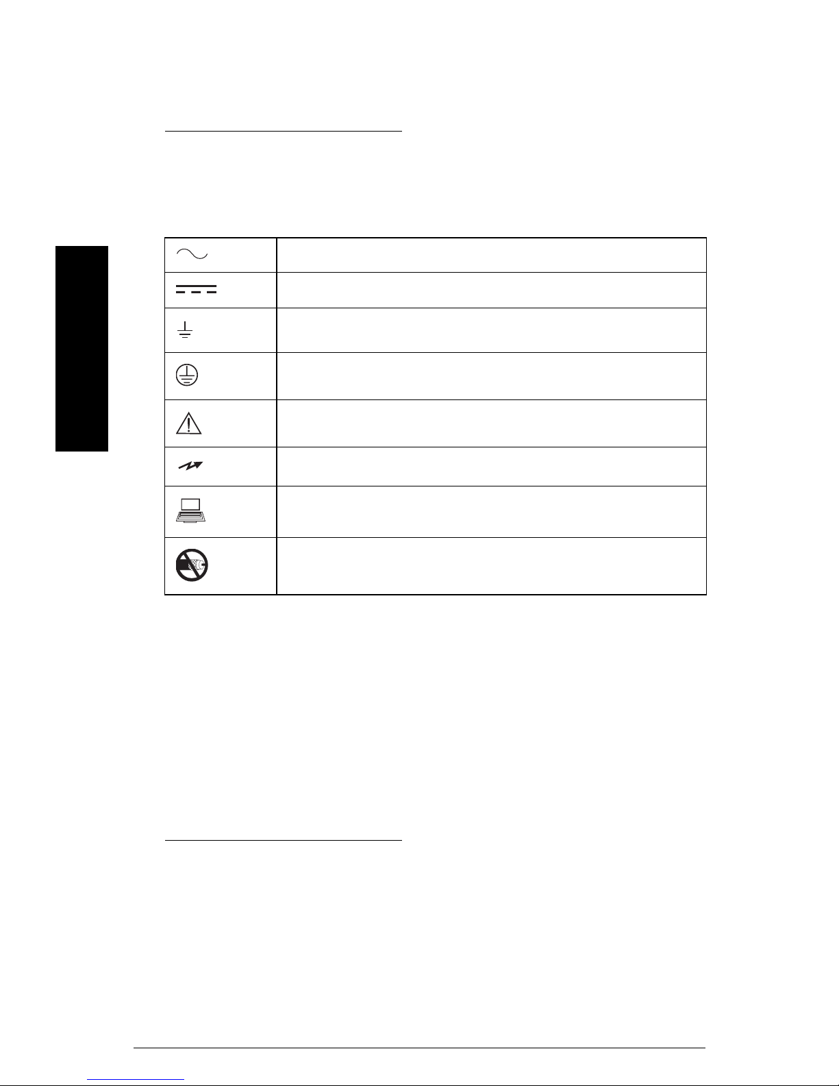
Manual Symbols
Please note their use carefully.
Alternating Current
Direct Current
Earth (ground) Terminal
mmmmm
Protective Conductor Terminal
HydroRanger 200
Caution (refer to instructions)
Infra-red communication port on front of instrument
RJ-11 communications port
No co-axial cable connections
Configuration Examples
The configuration examples used in this manual illustrate the versatility of the
HydroRanger 200. Because there is often a range of ways to approach an application,
other configurations may also apply.
In all examples, substitute your own application details. If the examples do not apply to
your application, check the applicable parameter reference for the available options.
Should you require more information, please contact your Siemens Milltronics
representative. For a complete list of Siemens Milltronics representatives, go to
www.siemens.com/processautomation
Page 2 HydroRanger 200 – INSTRUCTION MANUAL 7ML19985FC03
.

Specifications
Power
AC version
• 100-230 V AC ± 15%, 50 / 60 Hz, 36 VA (17W)
• fuse: F3: 2 AG, Slow Blow, 0.375A, 250V
1
DC version
• 12-30 V DC, 20W
• fuse: F3: 2 AG, Slow Blow, 2A, 250V
1
Transmitter fuse
• F1: Belling Lee, L754, 4000A HRC, ceramic type, 100mA, 250V
Temperature Sensor fuse
• F2: Belling Lee, L754, 4000A HRC, ceramic type, 50mA, 250V
Mounting
Location
• indoor / outdoor
Specifications
mmmmm
Altitude
• 2000 m max.
Ambient temperature
• -20 to +50 °C (-5 to +122 °F)
Relative humidity
• Wall Mount: suitable for outdoors (Type 4X / Nema 4X, IP65 Enclosure)
• Panel Mount: suitable for outdoors (Type 3 / Nema 3, IP54 Enclosure)
Installation category
•II
Pollution degree
•4
1.
Power consumption is listed at maximum.
7ML19985FC03 HydroRanger 200 – INSTRUCTION MANUAL Page 3

Range
• 0.3 m (1 ft) to 15 m (50 ft), dependent on transducer
Accuracy
• 0.25% of maximum range or 6 mm (0.24”), whichever is greater
Resolution
• 0.1% of program range1 or 2 mm (0.08”), whichever is greater
Memory
• 1 MB static RAM with battery backup
• 512 kB flash EPROM
Programming
Primary
• handheld programmer
Secondary
• PC running SIMATIC PDM
• PC running Dolphin Plus software
mmmmm
Display
Specifications
• back lit LCD
Temperature Compensation
• Range: -50 to +150 °C (-58 to +302 °F)
Source
• integral transducer sensor
• TS-3 temperature sensor
• programmable fixed temperature
Temperature Error
Sensor
• 0.09 % of range
1.
Program range is defined as the empty distance from the face of the transducer
(P006) plus any range extension (P801).
Page 4 HydroRanger 200 – INSTRUCTION MANUAL 7ML19985FC03

Fixed
• 0.17 % per °C deviation from programmed value
Outputs
Transducer drive
•315 V peak
mA Analog
HydroRanger 200 (all models):
Single or Dual point versions include two mA outputs
• 0-20 mA
• 4-20 mA
• 750 ohm maximum
• Resolution of 0.1%
•Isolated
Relays
1
•One:
•1 control
•Three:
•2 control
• 1 alarm control
•Six:
•4 control
• 2 alarm control
• All relays rated 5A at 250 V AC, non-inductive
Control Relays
• 1, 2 or 4 Form A, NO relays (numbers 1, 2, 4, 5)
Alarm Relay
• 0, 1 or 2 Form C, NO, or NC relay (numbers 3, 6)
Communication
• RS-232 running Modbus RTU and ASCII via RJ-11 connector
• RS-485 running Modbus RTU and ASCII via terminal blocks
Specifications
mmmmm
Optional
• SmartLinx® compatible
1.
All relays are certified only for use with equipment that fails in a state at or
under the rated maximums of the relays.
7ML19985FC03 HydroRanger 200 – INSTRUCTION MANUAL Page 5

Inputs
mA (analog) (1) [6 relay model]
• 0-20 or 4-20 mA, from alternate device, scalable
Discrete (2)
• 10-50 V DC switching level
• logical 0 = < 0.5 V DC
• logical 1 = 10 to 50 V DC
• 3 mA maximum draw
Enclosure
Wall Mount
• 240 mm (9.5") x 175 mm (6.9"). Width dimension includes hinges.
• Type 4X / NEMA 4X / IP 65
• Polycarbonate
1
Panel Mount
• 278 mm (10.93") x 198 mm (7.8") Width dimension includes flange.
• Type 3 / Nema 3 / IP54
• Polycarbonate
mmmmm
Specifications
Weight
• Wall mount: 1.37 kg (3.02 lb)
• Panel mount: 1.5 kg (3.3 lb)
Approvals
• See product nameplate
Compatible Transducers
• Echomax series and STH series
Transducer Frequency
•44 kHz
1.
For watertight applications, use only approved, suitable size hubs in the
enclosure’s conduit holes.
Page 6 HydroRanger 200 – INSTRUCTION MANUAL 7ML19985FC03

Cable
• Do not use coaxial cable for transducer (see General Appendix F: Upgrading on
page 246 for more information)
• transducer and mA output signal to be 2 copper conductors, twisted with shield/drain
wire, 300 Vrms, 0.324 - 0.823 mm
adjacent conductors @ 1kHz = 62.3 pF/m (19 pF/ft). Nominal capacitance between
conductor and shield @ 1kHz = 108.3 pF/m (33 pF/ft) (Belden®
• 365 m maximum
Note: The HydroRanger 200 is to be used only in the manner outlined in this
instruction manual or protection provided by the equipment may be impaired.
2
(22 - 18 AWG), nominal capacitance between
1
8760 is acceptable)
Specifications
mmmmm
1.
Belden is a registered trademark of Belden Wire & Cable Company.
7ML19985FC03 HydroRanger 200 – INSTRUCTION MANUAL Page 7

Installation
Notes:
• Installation must only be performed by qualified personnel, and in accordance
with local governing regulations.
• This product is susceptible to electrostatic shock. Follow proper grounding
procedures.
All field wiring must have insulation suitable for at least 250 V.
Hazardous voltage present on transducer terminals during operation.
DC terminals shall be supplied from an SELV source in accordance with IEC
1010-1 Annex H.
• The non-metallic enclosure does not provide grounding between conduit
connections. Use grounding type bushings and jumpers.
Mounting
Mounting Locations
Recommended
• Ambient temperature is always within -20 to +50 °C (-5 to +122 °F)
• HydroRanger 200 display window is at shoulder level, unless most interaction is
through a SCADA system
• Easy access for hand programmer is provided
mmmmm
Installation
• Cable length requirements are minimal
• Mounting surface is free from vibration
• Leave is sufficient room to swing unit lid open and have clear access.
• A place for a laptop computer is provided for on-site Simatic PDM configuration
Avoid
• Exposure to direct sunlight. (Provide a sun shield to avoid direct sunlight.)
• Proximity to high voltage/current runs, contacts, SCR or variable frequency motor
speed controllers
Page 8 HydroRanger 200 – INSTRUCTION MANUAL 7ML19985FC03
Mounting Instructions
The wall mount and panel mount units install differently. Please follow the specific
instructions for your unit.
Note: When routing cable through a conduit, please follow the Cable Routing
instructions on page 10 before mounting the HydroRanger 200.
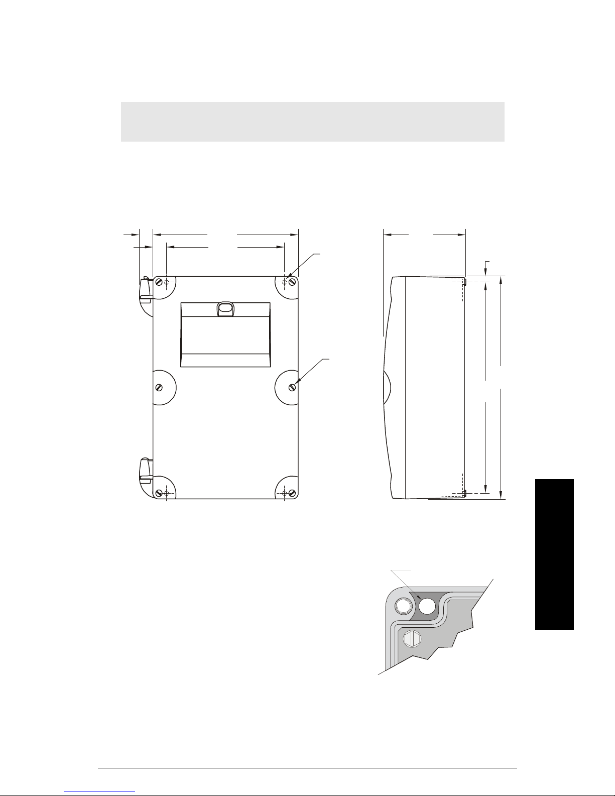
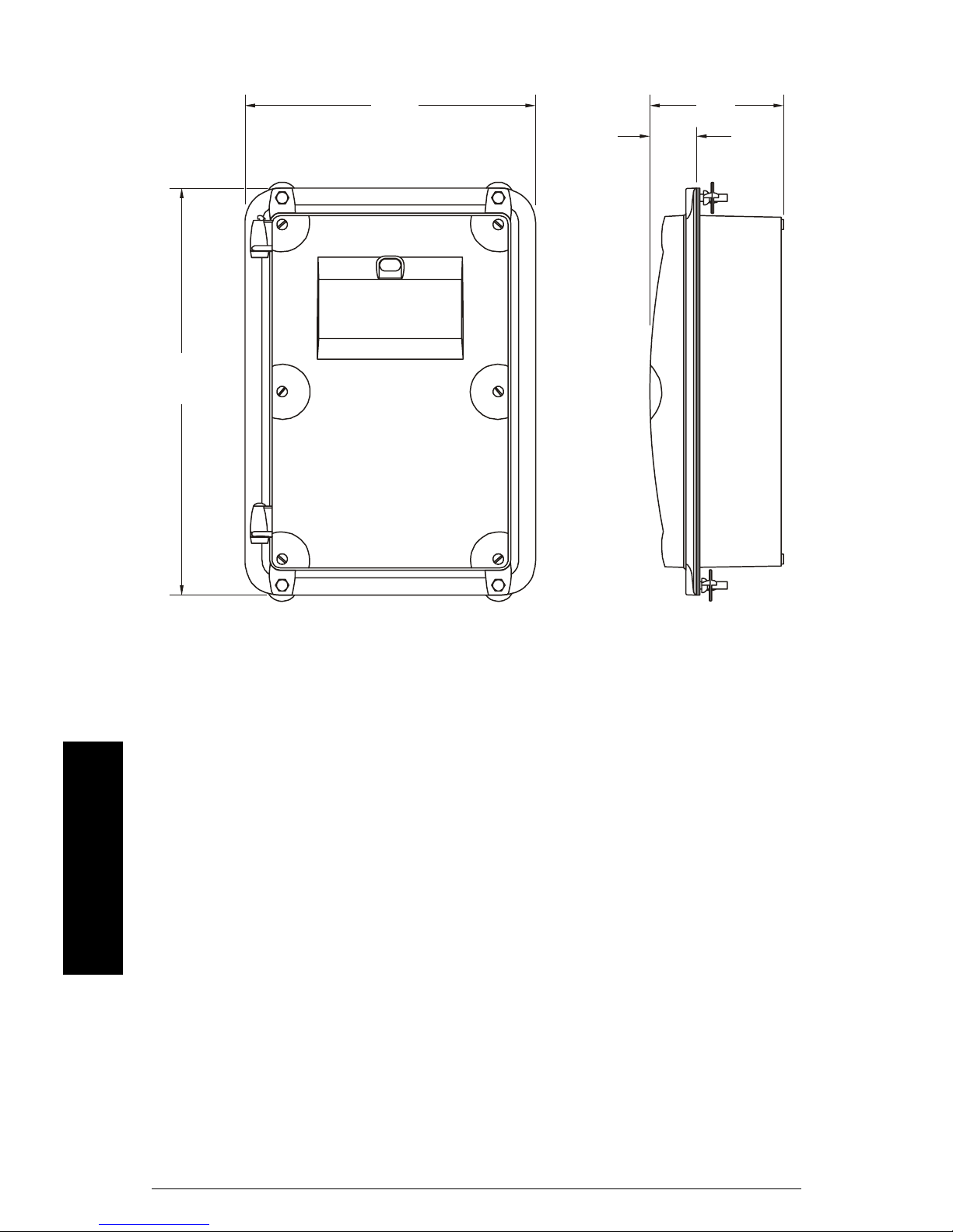
Wall Mount
Enclosure Dimensions
14.9 mm
(0.58")
15.2 mm
(0.6")
160.3 mm
(6.325")
130 mm
(5.125")
4.3 mm dia.
(0.17")
four mounting
holes
lid screws
(6)
91 mm
(3.58")
240 mm
227 mm
(8.93")
6.6 mm
(0.26")
(9.45")
Mounting the Enclosure
1. Remove the lid screws and open the lid to reveal the mounting screw holes.
2. Mark and drill four holes in the mounting
surface for the four screws (customer supplied).
3. Fasten with a long screwdriver.
Please note:
• Recommended mounting: directly to wall or to
electrical cabinet back panel
• Recommended mounting screws: #6
• If alternate mounting surface is used, it MUST
be able to support four times the weight of the
unit.
7ML19985FC03 HydroRanger 200 – INSTRUCTION MANUAL Page 9
Installation
mmmmm
mounting screw holes
Cable routed through a conduit:
1. Remove the four mounting screws holding the motherboard to the enclosure.
2. Be careful not to damage the electronics with static electricity. Remove the
motherboard from the enclosure by pulling the board straight out.
3. Drill the required cable entry holes. Make sure conduit holes do not interfere with
the lower areas on the terminal block, circuit board, or SmartLinx card.
4. Attach the conduit to the enclosure using only approved suitable size hubs for
watertight application.
5. Reinstall the motherboard with the mounting screws.
suitable location for conduit entrances
.
Note: For conduit locations and assembly for hazardous mounting in Class 1 Div 2
applications, please see Drawing 23650314 in
1, Div 2 Applications
on page 249.
Appendix G: Conduit Entry for Class
Cable exposed and entering through the cable glands:
1. Unscrew the glands and attach them loosely to the enclosure.
2. Thread the cables through the glands. Ensure the power cable is kept separated
from the signal cables and then wire the cables to the terminal blocks.
mmmmm
3. Tighten the glands to form a good seal.
Installation
Note: Where more holes are required than are supplied in the enclosure, follow
the
Cable routed through a conduit
steps.
Page 10 HydroRanger 200 – INSTRUCTION MANUAL 7ML19985FC03
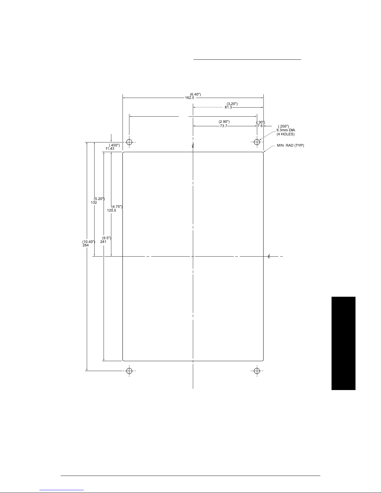
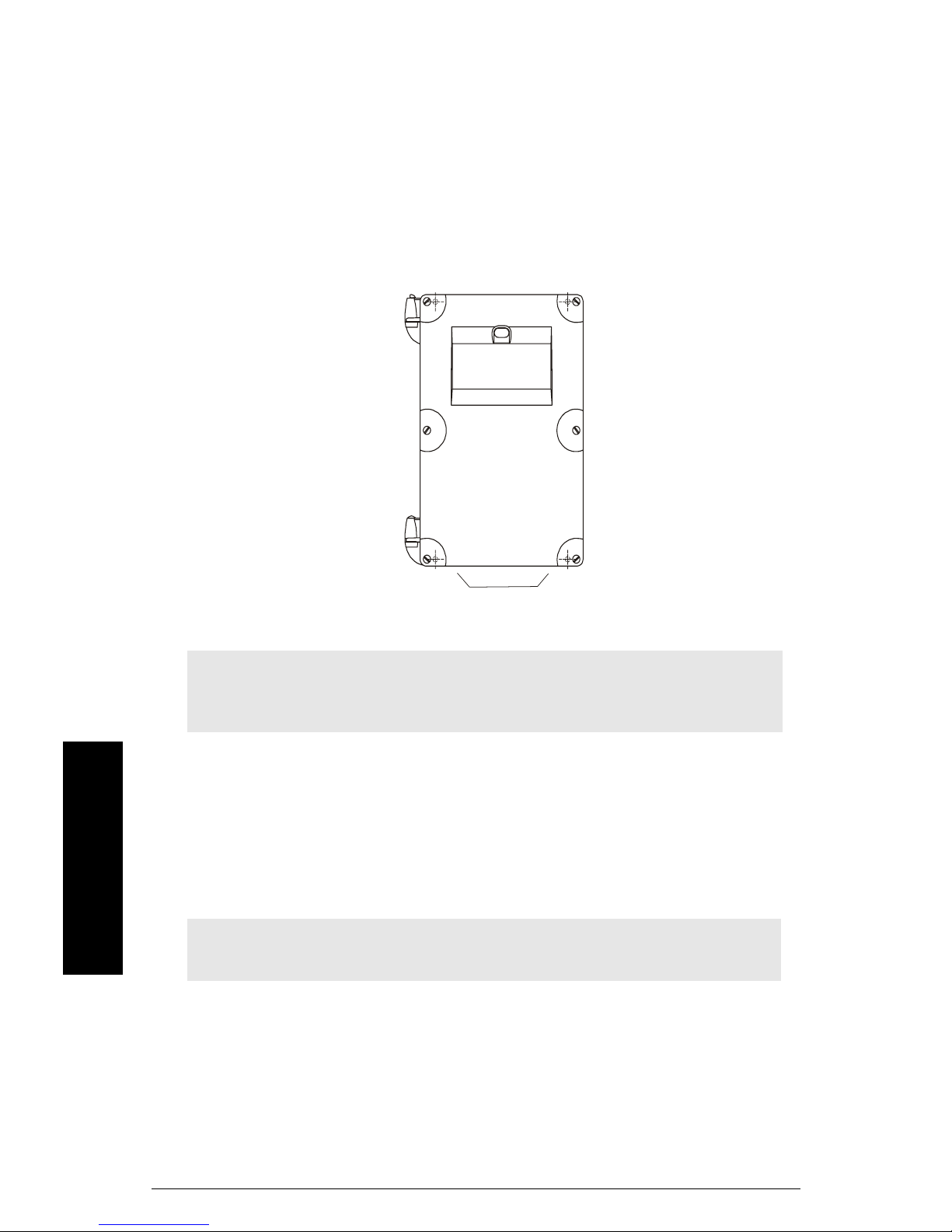
Panel Mount
Installing the panel mount unit requires making a cutout in the panel. The dimensions for
the cutout are provided in the illustration below. A full size cutout template is provided
with your unit or may be downloaded from www.siemens.com/processautomation
Cutout Dimensions
.
Cutout Instructions
1. Select a place for the unit and fasten the template onto the panel (use tape or
tacks).
2. Drill the four fastener holes.
3. Make the cutout using the appropriate tools.
4. Mount unit according to the instructions in this manual.
7ML19985FC03 HydroRanger 200 – INSTRUCTION MANUAL Page 11
Installation
mmmmm
Panel Mount Dimensions
278 mm
(10.93")
198 mm
(7.80")
97 mm
(3.82")
36 mm
(1.40")
Mounting the Enclosure
Once cutout is complete and mounting holes are drilled, follow these steps:
1. Remove lid from unit by undoing the six lid screws and lifting it off its hinges.
2. Remove the four screws holding the motherboard to the enclosure.
3. Be careful not to damage the electronics with static electricity. Remove the
motherboard from the enclosure by pulling the board straight out.
4. Drill the required cable entry holes. Be sure to compensate for panel door
dimensions and make sure conduit holes do not interfere with the lower areas on
mmmmm
Installation
the terminal block, circuit board, or SmartLinx card.
5. Replace board and fasten the four screws.
6. Place the unit into the panel and insert hexagonal fasteners through bevel slots and
predrilled panel holes.
7. Fasten with wingnuts and hand tighten.
8. Add conduit or glands and wire as required, then replace the lid.
Helpful hint:
• Use tape to hold hexagonal heads in slots while attaching wingnuts.
Page 12 HydroRanger 200 – INSTRUCTION MANUAL 7ML19985FC03
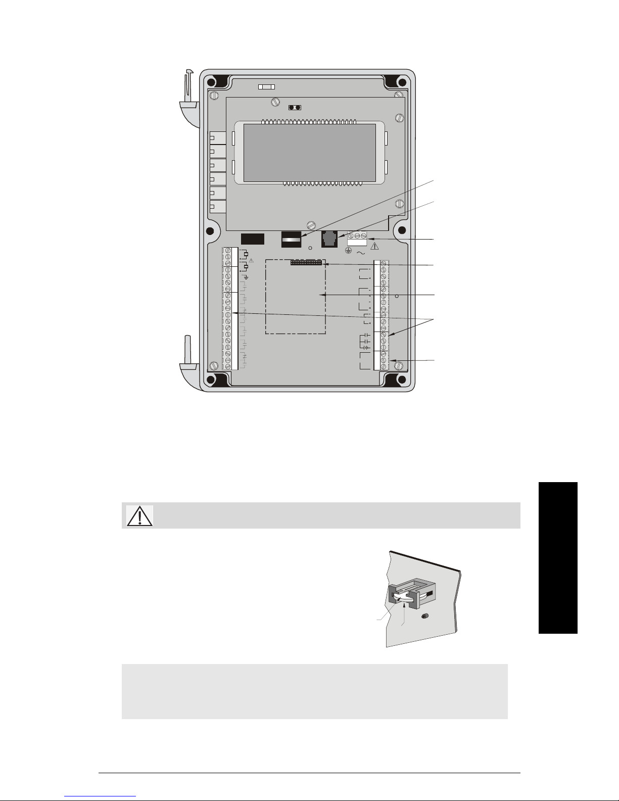
HydroRanger 200 Board
Battery
RS-232 RJ-11
Connector
DISCRETE
INPUTS
L2/N L1
mA INPUT
4 - 20 mA
OUTPUTS
RS485
SHIELD
TS-3
SHIELD
TB1
TB3
SYNC
1
2
Female Connector
for SmartLinx Card
SmartLinx Card
Te rm i n a l s
1
2
COM
A
B
RS-485
Connections
TB2
2
1
RELAY 1
RELAY 2
RELAY 3
RELAY 4
RELAY 5
RELAY 6
Installing the Battery
The battery (Rayovac BR2032) has a ten-year life expectancy. Please note the life
expectancy may be reduced by ambient temperature. If the unit loses external and
battery power, a capacitor will power the RAM for about ten minutes.
Disconnect power before replacing the battery.
Power Supply
Installation
Installation Steps
1. Open the enclosure lid.
2. Slide the battery into the holder. Be sure to
align the + and – terminals correctly.
3. Close and secure enclosure lid.
Note: All parameter values are written to the EEPROM once every hour. The
battery is used to backup Standard Data Logging parameters (P300-P321)
between writes, in case of power failure.
7ML19985FC03 HydroRanger 200 – INSTRUCTION MANUAL Page 13
mmmmm
Battery
+

Installing SmartLinx Card
SmartLinx cards are generally pre-installed. If unit does not have a SmartLinx card, follow
these steps to install one.
1. Align card with the two mounting posts and then press-fit with the female
connector.
2. Use the screws supplied with the card to attach it to the mounting posts.
3. Wire in the SmartLinx card according to SmartLinx Manual.
mmmmm
Installation
Page 14 HydroRanger 200 – INSTRUCTION MANUAL 7ML19985FC03
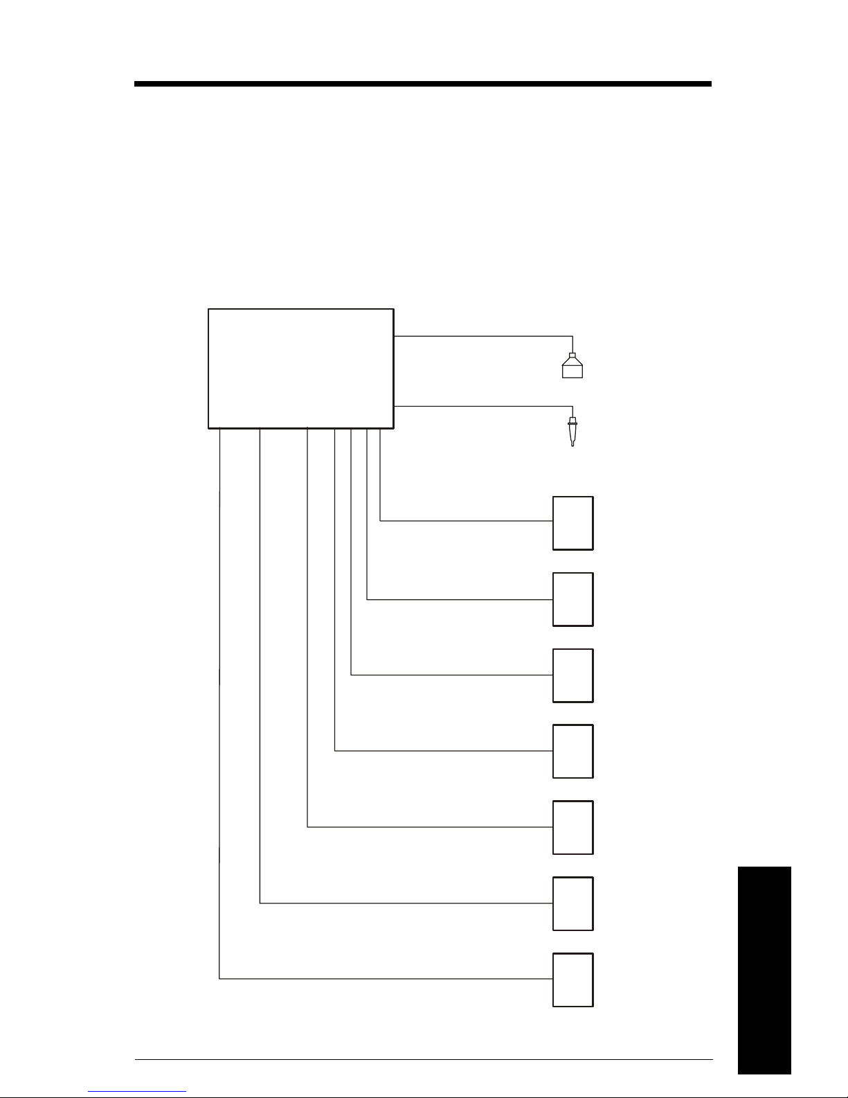
Wiring
Please note:
• Verify that all system components are installed in accordance with instructions.
• Connect all cable shields to the HydroRanger 200 Shield Terminals. Avoid differential
ground potentials by not connecting cable shields to ground (earth) anywhere.
• Keep exposed conductors on shielded cables as short as possible to reduce noise
on the line caused by stray transmissions and noise pickup.
HydroRanger 200
Siemens Milltronics
Transducer(s)
Siemens Milltronics
TS-3 Temperature
Sensor
Laptop running
Dolphin Plus
Customer Alarm,
Pump, or Control
Device
Customer Device,
digital output
Customer Device,
analog output
7ML19985FC03 HydroRanger 200 – INSTRUCTION MANUAL Page 15
Customer Network or
Modem
SmartLinx Card
Display, PLC, Chart
recorder, or other
Control Device
Wiring
mmmmm
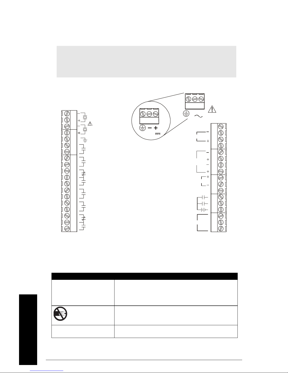
Terminal Board
The terminal board on the HydroRanger 200 allows all inputs and outputs to be connected
simultaneously.
Note: Recommended torque on terminal clamping screws.
• 0.56 - 0.79 Nm
• 5 - 7 in.lbs
Please do not overtighten the screws.
TB1
TB2
2
1
RELAY 1
RELAY 2
RELAY 3
RELAY 4
RELAY 5
RELAY 6
12-30 V
DC Version
TB1
L2/N L1
mA INPUT
4 - 20 mA
OUTPUTS
DISCRETE
INPUTS
RS485
TB3
SYNC
SHIELD
1
2
TS-3
SHIELD
1
2
COM
A
B
Cables
The HydroRanger 200 transceiver requires a shielded two-wire connection to the
transducer.
Connection Cable Type
mA input and mA output
sync, Temperature sensor,
discrete input, dc input
Transducer
Relay output
mmmmm
Wiring
AC input
1.
Preferred shielding is braided screen.
Page 16 HydroRanger 200 – INSTRUCTION MANUAL 7ML19985FC03
1
2 copper conductors, twisted, with shield
300V 0.324 - 0.0.823 mm
2
(22 - 18 AWG)
/drain wire,
Maximum length: 365 m
Do not use a coaxial transducer cable extension with the
HydroRanger 200. Electrical noise interference affects
performance.
Relay to be copper conductors per local requirements to
meet 250 V 5A contact rating.
Transducers
Warning: Hazardous voltage present on transducer terminals during
operation.
Run the transducer cable in a grounded metal conduit, separate from other
wiring (except TS-3 temperature sensor wiring, if applicable).
Notes:
• Do not use coaxial cable because of electrical noise interference
• Do not connect the shield and white transducer wires together; wire to separate
terminals
• Disregard older transducer manuals that recommend these practices
white
TRANSDUCER TWO
black
white
TRANSDUCER ONE
black
A 0.1 µF (100V or greater) capacitor is included with the HydroRanger 200 for retrofitting
old HydroRanger installations. Please see
HydroRanger Installations)
on page 247.
HydroRanger 200 Installation (for retrofitting
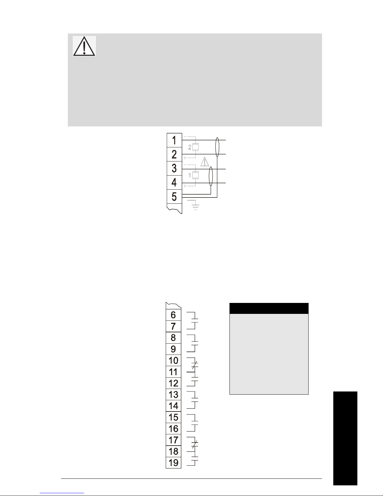
Relays
Relay contacts are shown in the de-energized position. All relays are handled identically
and can be configured as positive or negative logic using P118.
Relay Ratings
• four Form A, NO
relays(1,2,4,5)
• two Form C, NO or
NC relays (3,6)
• 5A at 250Vac, noninductive
RELAY 1
RELAY 2
RELAY 3
Power Failure
Relays 1, 2, 4, and 5 are
normally open and will fail
in the normal state.
Relays 3 and 6 can be
wired either normally open
or normally closed, and
will fail in their deenergized states.
7ML19985FC03 HydroRanger 200 – INSTRUCTION MANUAL Page 17
RELAY 4
RELAY 5
RELAY 6
Wiring
mmmmm
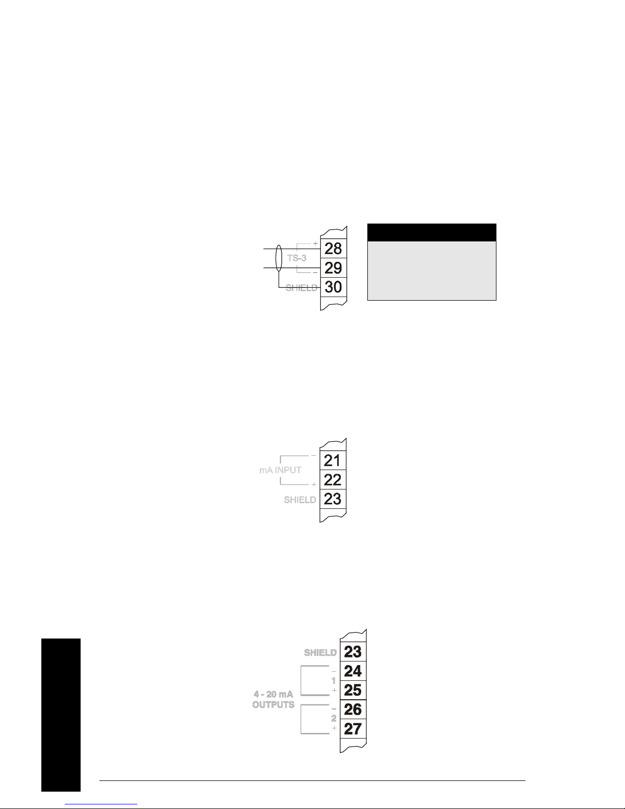
Temperature Sensor
Accurate temperature readings are critical to accurate level measurements because the
speed of sound changes, depending on air temperature, and all Siemens Milltronics
Echomax and ST-H transducers have an internal temperature sensor.
If the following conditions apply, a separate TS-3 temperature sensor will ensure
optimum accuracy:
• the transducer is exposed to direct sunlight (or other radiant heat source)
• the transducer face and monitored surface temperature differs
• faster response to temperature changes is required
Note
TEMPERATURE SENSOR
Use a T-S3 Temperature
Sensor only. Leave
terminals open (unused) if
TS-3 is not deployed.
mA Input [6 relay model]
For more information, consult the Transducer (P004) and mA Input Parameters (P250,
P251, and P252) in the parameter reference section.
mA Output
For more information, consult the mA output parameters (P200 to P219) in the parameter
reference section.
mmmmm
Wiring
Page 18 HydroRanger 200 – INSTRUCTION MANUAL 7ML19985FC03
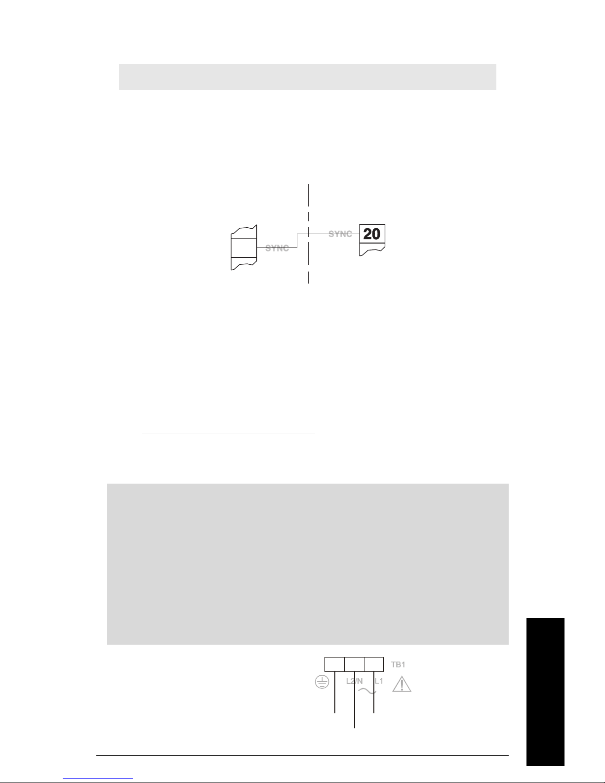
Level System Synchronization
Note: The HydroRanger 200 CANNOT be synchronized with the HydroRanger.
When using multiple ultrasonic level monitors, be sure to run the transducer cables in
separate grounded metal conduits.
When separate conduits are not possible, synchronize the level monitors so that no unit
transmits while another is waiting for echo reception.
Other Siemens
Milltronics Transceiver
HydroRanger 200
Synchronizing with another HydroRanger 200, or other Siemens Milltronics
instruments (DPL+, SPL, XPL+, LU01, LU02, LU10, LUC500, Hydro+,
EnviroRanger, MiniRanger):
• Mount the level monitors together in one cabinet
• Use a common power (mains) supply and ground (earth) for all units
• Interconnect the SYNC terminals of all level monitors
•Set parameter
P726 Level System Sync
on page 190.
• Contact Siemens Milltronics or your local distributor. Go to
www.siemens.com/processautomation.
Power
Important!
Before applying power to the HydroRanger 200 for the first time, ensure any
connected alarm/control equipment is disabled until satisfactory system operation
and performance is verified.
Notes for AC power connections
• The equipment must be protected by a 15 A fuse, or circuit breaker in the
building installation.
• A circuit breaker or switch in the building installation, marked as the disconnect
switch, must be in close proximity to the equipment and within easy reach of the
operator.
Note: Make sure unit is
connected to a
reliable ground.
7ML19985FC03 HydroRanger 200 – INSTRUCTION MANUAL Page 19
Ground
GND
Wiring
mmmmm
L1
L2/N

Digital Communications
Wiring the HydroRanger 200 for communications allows it to be integrated into a full
SCADA system or an industrial LAN.
The HydroRanger 200 can also be directly connected to a computer running Dolphin Plus.
RS-232 Serial Connection
TB2
2
1
RELAY 1
RELAY 2
RELAY 3
RELAY 4
RELAY 5
RELAY 6
RS-485 Serial Connection
DISCRETE
INPUTS
L2/N L1
mA INPUT
4 - 20 mA
OUTPUTS
TB1
TB3
SYNC
SHIELD
1
2
TS-3
SHIELD
1
2
COM
RS485
A
B
Connector
RS-485
Connection
(see below)
RS-232 RJ-11
Discrete Inputs
Discrete inputs have a positive and negative terminal. Requires an external power supply.
mmmmm
Wiring
Page 20 HydroRanger 200 – INSTRUCTION MANUAL 7ML19985FC03
Discrete Input (post.) 1
Discrete Input (pos.) 2
Common (neg.) for Discrete Input
 Loading...