


Over-the-Range Microwave
- 9000568352
Installation Instructions
For Models: HMV9302, HMV9303, HMV9305, HMV9306, HMV9307
PLEASE READ ENTIRE INSTRUCTIONS BEFORE PROCEEDING
IMPORTANT: Save these instructions for the local electrical inspector’s use.
INSTALLER: Please leave these Installation Instructions with this unit for the owner.
OWNER: Please retain these instructions for future reference.
Printed in Korea
P/No.: 3828W5U0503
Household Appliances
YOUR SAFETY FIRST
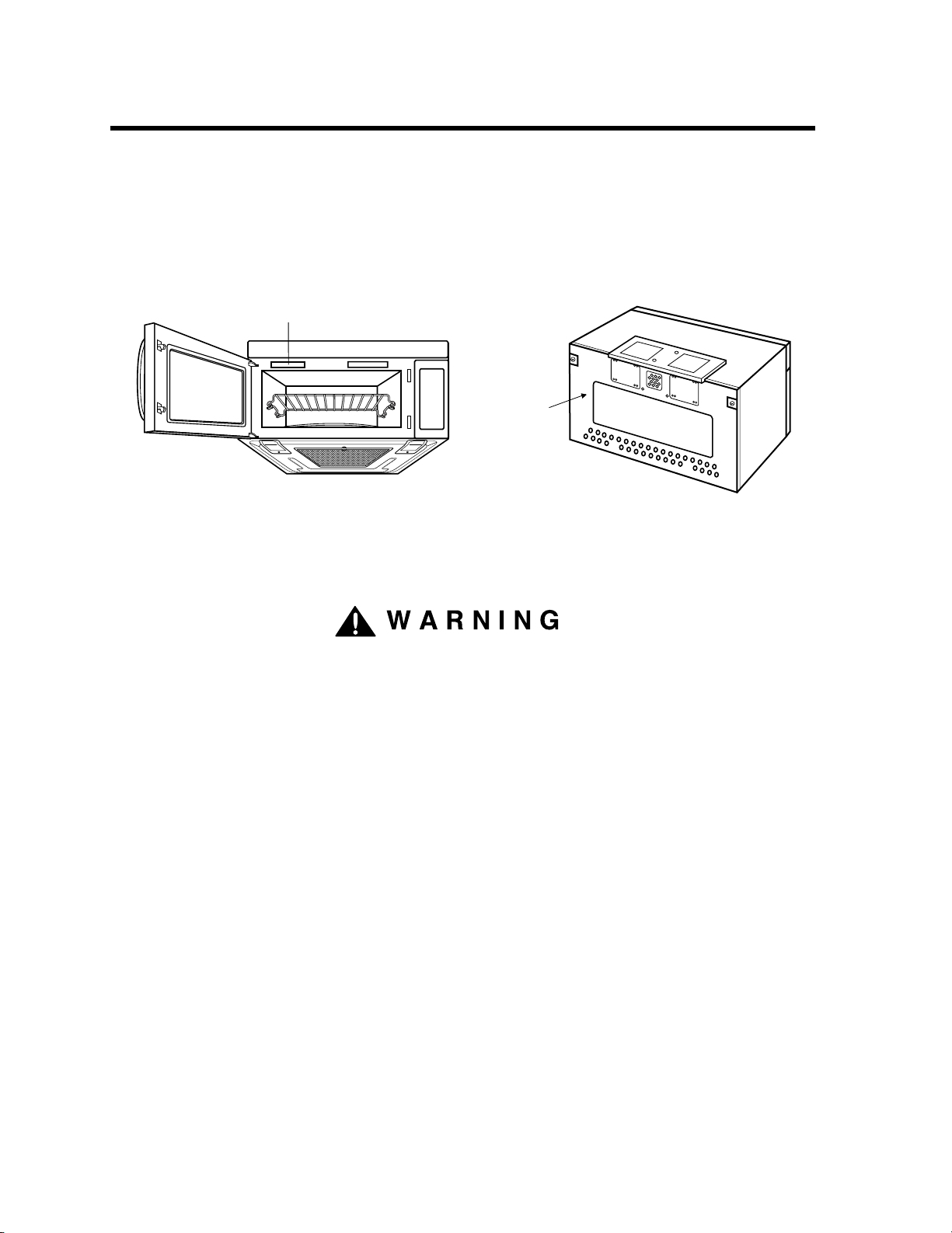
Mounting
plate
( Remove from
oven to install. )
Back of oven
Figure 1 Figure 2
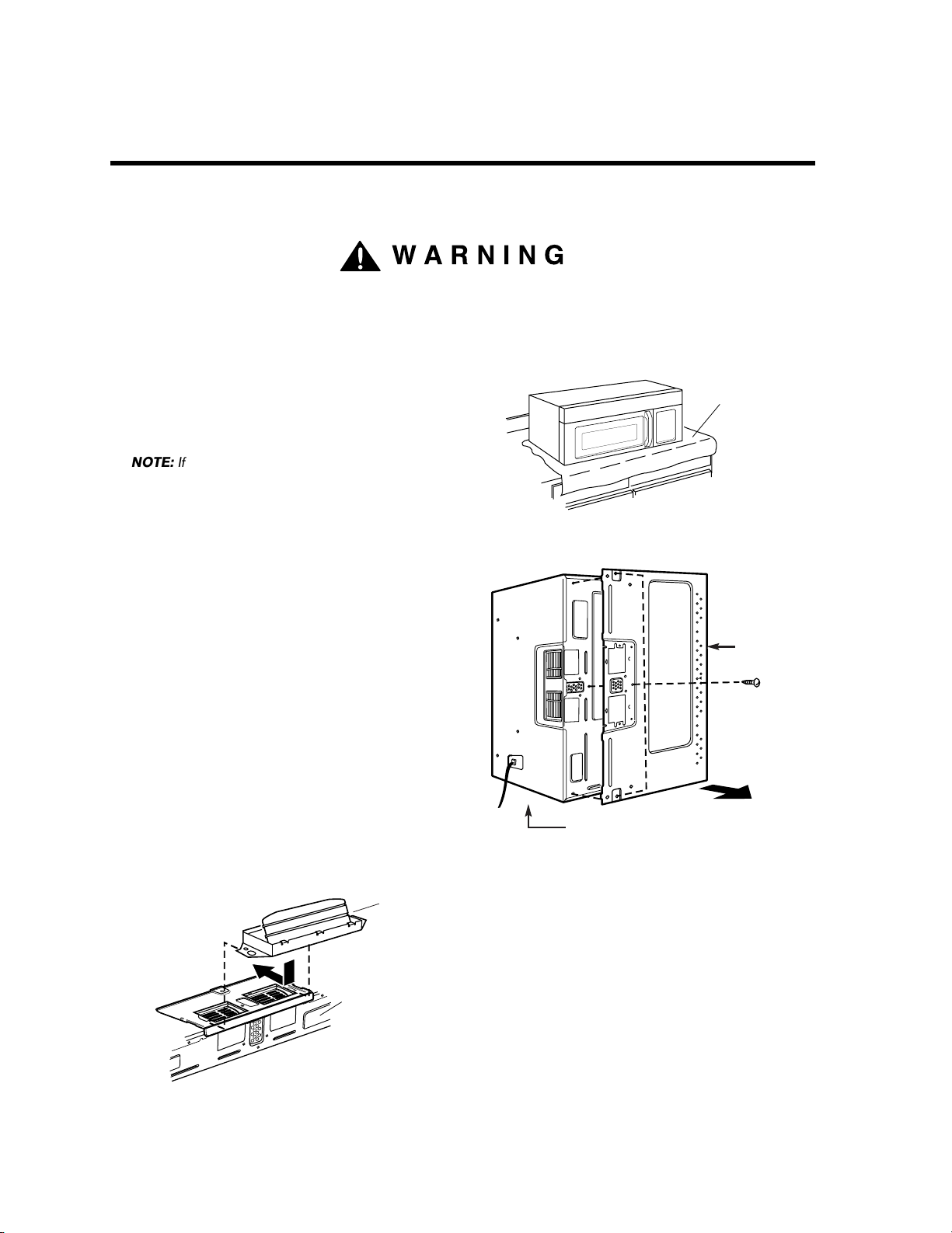
Model Number Label
WARNING
BEFORE YOU START
• Proper installation is the installer's responsibility!
– Read the entire manual before you begin. The Model number label is located on the oven front. See Figure 1.
Mounting plate is located on back side of microwave oven. See Figure 2.
BE SURE TO READ THE FOLLOWING SAFETY INSTRUCTIONS:
FOR YOUR SAFETY:
• You will need TWO people to install this oven. It is heavy and could cause personal injury if not handled properly.
The dimensions of the oven are as follows:
Height : 16
Width : 29
Depth : 15
Weight : 60 lbs.
• Avoid Electrical Shock!
– Before you drill into the wall, note where electrical outlets are and where electrical wires might be concealed
behind the wall. YOU COULD GET AN ELECTRIC SHOCK if you contact electrical wires with your drill bit.
– Locate and disconnect the power to any electrical circuits that could be affected by installing this oven.
IF YOU DO NOT DISCONNECT THE POWER, YOU COULD GET AN ELECTRIC SHOCK.
• ELECTRICAL RATING OF THIS OVEN : 120V AC 60Hz.
– You need a DEDICATED 120V, 60Hz, AC only, 15 or 20A, fused electrical supply (located in the cabinet above
the microwave as close as possible to the microwave) serving only the microwave.
7/16 inches
15/16 inches
5/8 inches
2
YOUR SAFETY FIRST
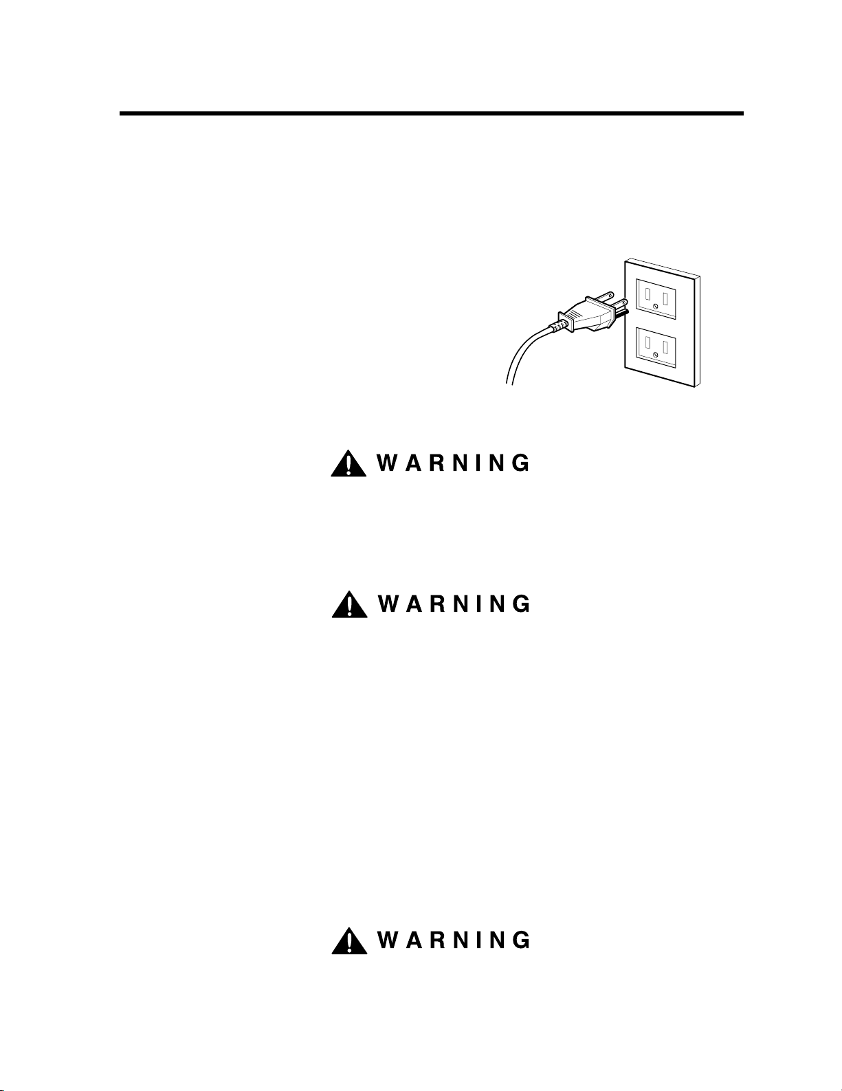
PROPERLY POLARIZED AND
GROUNDED OUTLET
Three-Pronged (Grounding) Plug
Figure 3
WARNING
WARNING
WARNING
• THIS APPLIANCE MUST BE GROUNDED!
– If there is an electrical short circuit, grounding reduces the risk of electrical shock by providing an escape wire
for the electric current. This appliance is equipped with a cord having a grounding wire with a grounding plug.
• Place the plug into a properly installed and grounded outlet. See Figure 3.
• Do not use an extension cord.
• Keep the power cord dry and do not pinch or crush it.
• DO NOT, UNDER ANY CIRCUMSTANCES, REMOVE THE
POWER SUPPLY CORD GROUNDING PRONG!
This appliance MUST be grounded!
If you use the grounding plug improperly, you risk electric shock!
– Check with a qualified electrician if you are not sure whether the oven is properly grounded or if you do not
completely understand the grounding instructions.
DO NOT USE A FUSE IN THE NEUTRAL OR GROUNDING CIRCUIT.
Improper grounding could result in electric shock or other personal injury.
SAVE THESE INSTRUCTIONS FOR THE LOCAL ELECTRICAL INSPECTOR'S USE.
• DO NOT EXPOSE YOURSELF TO EXCESSIVE MICROWAVE ENERGY!
– DO NOT try to operate the microwave oven with the door open.
– DO NOT tamper with or defeat the safety interlocks.
– DO NOT place objects between the microwave oven front face and the door.
–
DO NOT allow soil or cleaner residue to build up on the flat surfaces around the microwave oven door.
– DO NOT operate the microwave oven if it is damaged.
– The microwave oven door must close properly to operate safely.
– DO NOT USE THE MICROWAVE OVEN:
• If the door is bent.
• If the hinges or latches are broken or loose.
• If the door sealing surfaces or glass is broken or cracked.
– DO NOT ATTEMPT TO ADJUST OR REPAIR THE OVEN YOURSELF!
It should be adjusted and repaired by a qualified technician who can check for microwave leakage after
repairing the oven.
If you do not use the microwave oven as instructed,
you could be exposed to excessive microwave energy.
3
YOUR SAFETY FIRST
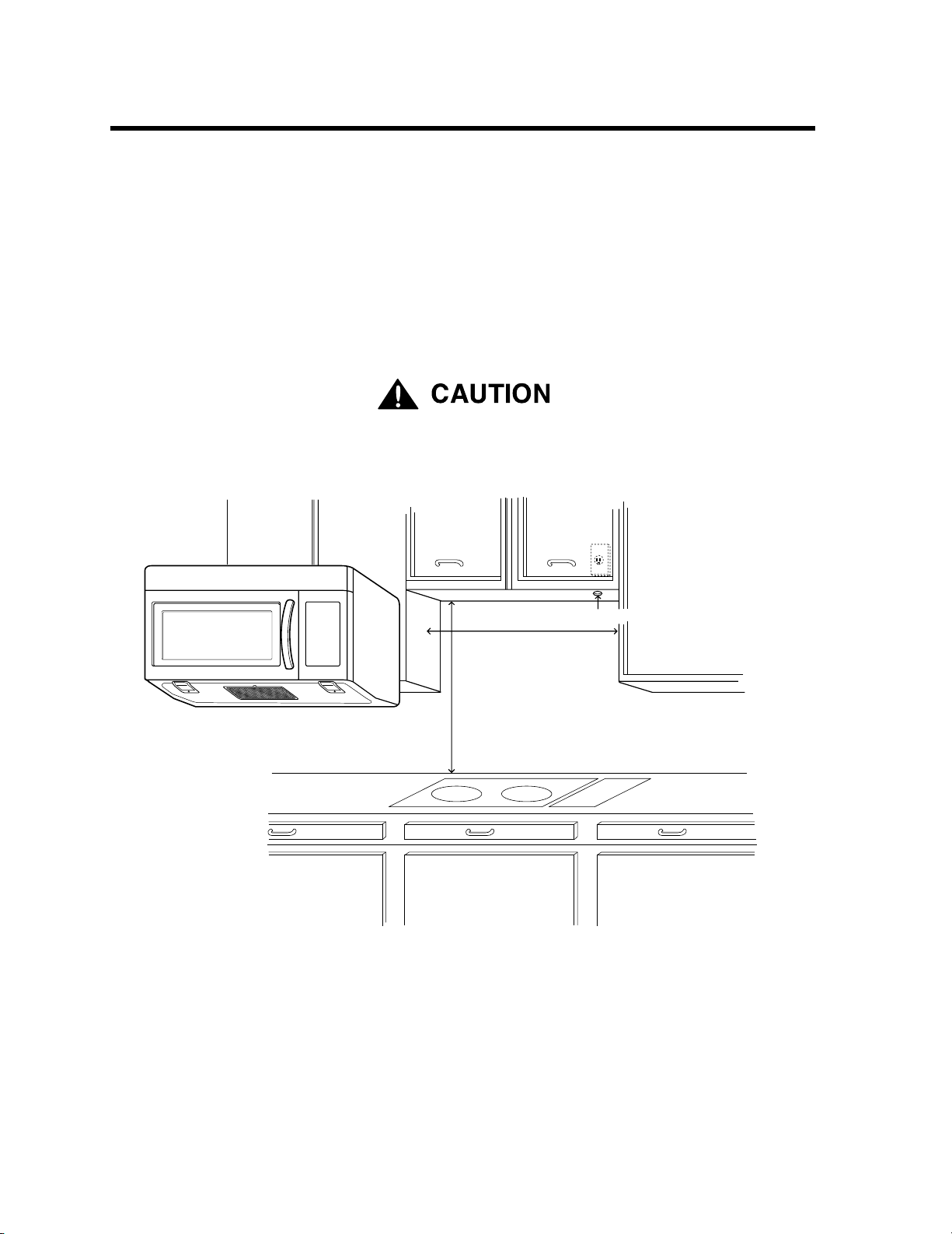
30" min. cabinet opening width
30" min. clearance from bottom
of cabinet to cooking surface
or countertop
(Use templates included
with installation instructions)
Grounded Outlet
(inside upper cabinet)
Power Supply Cord Hole
Figure 4
CAUTION
• MAKE SURE YOU HAVE ENOUGH SPACE AND SUPPORT.
– Mount the oven against a flat, vertical wall, so it is supported by the wall. The wall should be constructed of
minimum 2" x 4" wood studding and 3/8" thick drywall or plaster/lath.
– ATTACH AT LEAST ONE of the two lag screws supporting the oven to a vertical, 2" x 4" wall stud.
– DO NOT mount the microwave oven to an island or peninsula cabinet.
– BE SURE the upper cabinet and rear wall structures are able to support 150 lbs., plus the weight of any items
you place inside the oven or upper cabinet.
– Locate the oven away from strong draft areas, such as windows, doors, and strong heating vents.
– BE SURE you have enough space. See Figure 4 below for minimum vertical and horizontal clearance.
If you do not mount the oven as instructed,
you risk personal injury and/or property damage.
CAUTION
•
Before you begin installing the oven, PLACE A PIECE OF THE CARTON OR OTHER HEAVY
MATERIAL (such as a blanket) over the countertop or cooktop to protect it. Do not use a plastic cover.
Failure to protect these surfaces could result in property damage.
4
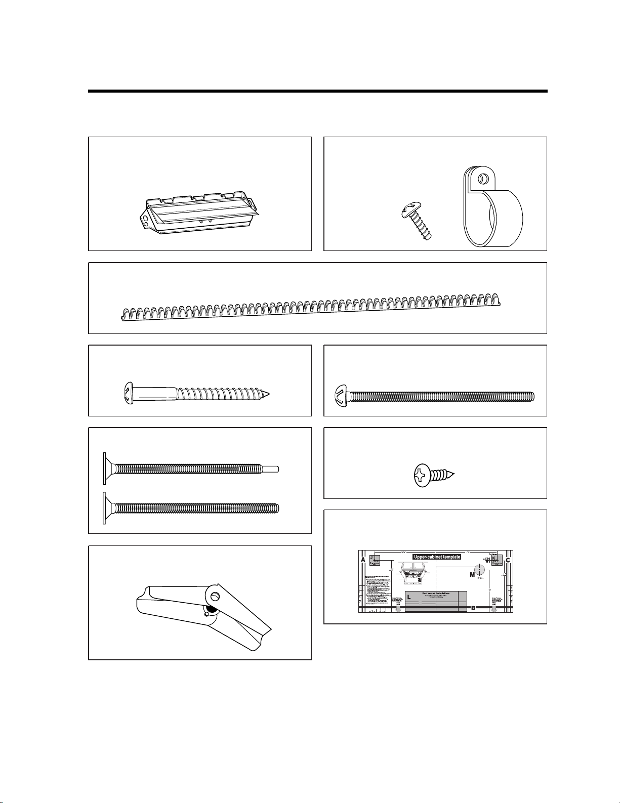
PARTS, TOOLS, MATERIALS
Damper/duct connector
(for roof vented or wall vented installation)
Not Actual Size
Four 1/4" x 2" lag screws - Actual Size
(for wall stud holes)
Four 1/4" x 3" toggle bolts - Actual Size
(for drywall holes)
Two 1/4" x 3" bolts - Actual Size
OR
(for securing to the upper cabinet)
Four spring toggle heads - Actual Size
(for the toggle bolts)
Left side
Right side
centerline
6"
4"
8"
12"
10-
8-
11
Roof-venting installation
Upper-cabinet template
B
C
D
10-
3
16
One upper cabinet template - Not Actual
Size
Two tapping screws - Actual Size
(for attaching the damper duct connector)
One power cord clamp bushing - Actual Size (for the cord hole in a metal upper cabinet)
One power cord clamp and
One dark-colored mounting screw
(to hold the power cord)
Actual Size
THE FOLLOWING PARTS ARE SUPPLIED WITH THE OVEN:
NOTE: Depending on your ventilation requirements, you may not use all of these parts.
NOTE: You need to install at least one lag screw into a 2" x 4" stud and four anchor bolts into the wall,
and the mounting area must meet the 150 lbs. weight requirement.
5
PARTS, TOOLS, MATERIALS
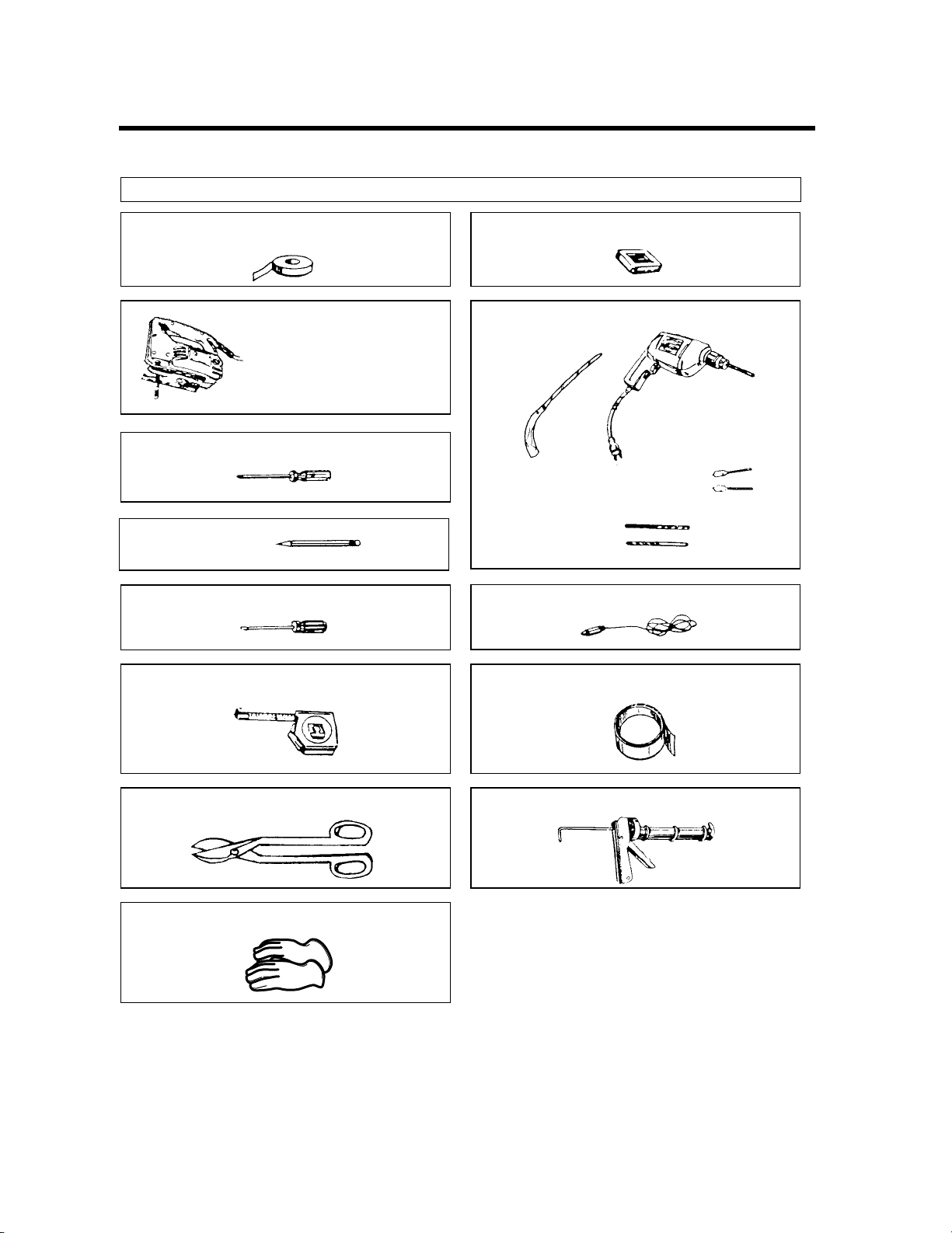
YOU WILL NEED THE FOLLOWING TOOLS AND MATERIALS FOR THE INSTALLATION:
Carton or other heavy material for covering the counter top.
Clear tape
(for taping the templates to the wall)
Saber saw (for cutting vent
holes for roof or wall venting)
Phillips screwdriver
Pencil
Flat blade screwdriver
Stud finder or thin nail.
Keyhole saw (for the power cord hole)
Electric drill
3/8" and 3/4" wood drill bits
1/2" and 3/16"
drill bits
Plumb line
Measuring tape (metal preferred)
Small side cutters or tin snips
Gloves
Duct Tape
Caulking gun
• If you have brick or masonry walls, you will need special hardware and tools.
• The ductwork you need for the installation is not included. All wall and roof caps must have a back-draft damper
(shown on page 5).
6
STEP 1: PREPARE THE
Grounded Outlet
( Inside Cabinet )
Upper
Cabinet
Power-Supply-Cord Hole
Figure 4 Detail
WARNING
WARNING
ELECTRICAL CONNECTIONS
AVOID ELECTRICAL SHOCK! THIS APPLIANCE MUST BE GROUNDED!
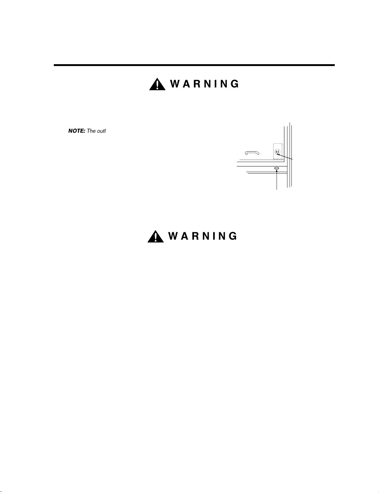
1. Locate the grounded electric outlet for this oven in the cabinet
above the oven, as shown in Figure 4 Detail.
NOTE: The outlet should be on a circuit dedicated to the
microwave oven 120V, 60Hz., AC only with a 15 or
20A fused electrical supply.
IMPORTANT: If you do not have the proper wall outlet, you
MUST have one installed by a qualified
electrician.
2. You will cut the power-supply-cord hole (shown in Figure 4 Detail)
later when you prepare the wall and upper cabinet in Step 4.
NOTE: Do not use an extension cord.
Keep the power cord dry and do not pinch or crush it.
Improper grounding could result in
electric shock or other personal injury.
• DO NOT, UNDER ANY CIRCUMSTANCES, REMOVE THE POWER SUPPLY
CORD GROUNDING PRONG! This appliance MUST be grounded!
7
STEP 2:
Wall-venting
through-the-wall
wall cap
3 1/4"x10"
duct
Figure 7
cabinet
oven
PREPARE THE VENTING SYSTEM
NOTE: The ductwork you need for outside ventilation is not included with your oven. The standard ductwork
fittings and length are shown in Figure 9, page 9.
WARNING:FIRE HAZARD
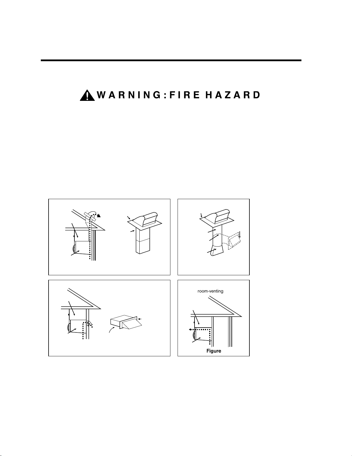
THIS OVEN MUST BE PROPERLY VENTED!
You may vent your oven in one of three ways:
Roof-venting If your oven is located on an outside wall near the roof, as in Figures 5 (31/4" x 10" duct)
and 6 (6" round duct.)
Wall-venting If your oven is located on an outside wall on the first floor of your house, as in Figure 7
(31/4" x 10" duct) and Figure 6 (6" round duct.)
Room-venting If your oven is located on an inside wall of your house, as in Figure 8.
NOTE: If you choose the rear exhaust method (roof- or wall-venting), be sure there is enough clearance within the
wall for the exhaust duct.
“roof-venting”
roof cap
cabinet
3 1/4"x10"
duct
oven
Roof-venting
Figure 5
through-the-roof
“wall-venting”
REMEMBER AS YOU INSTALL THE VENTING:
roof cap
6" min.
diameter
round duct
elbow
3 1/4" to round
duct transition
room-venting
cabinet
oven
3 1/4" to round
ductwork transition
Figure 6
Figure 8
wall cap
• Keep the length of the ductwork and the number of elbows to a minimum to ventilate your oven efficiently.
See examples on page 9.
• Keep the size of the ductwork the same.
• Do not install two elbows together.
• Use duct tape to seal all joints in the duct system.
• Use caulking to seal the exterior wall or roof opening around the cap.
8
STEP 2:
Figure 9
Examples
For 3 1/4"x10" SYSTEMS
1-3 1/4" x 10" 90
o
elbow
1-Wall Cap
8 feet straight duct
TOTAL LENGTH
1-transition
2-90
o
elbows
1-Wall Cap
8 feet straight
TOTAL LENGTH
For 6" ROUND SYSTEMS
1
4567
23
3 1/4"x10"
to 6"=5ft.
90o elbow
=10ft.
45o elbow
=5ft.
3 1/4"x10"
wall cap
=40ft.
3 1/4"x10"
flat elbow
=10ft.
3 1/4"x10" roof
cap=24ft.
3 1/4"x10" 90˚
elbow=25ft.
6ft.
2ft.
2ft.
3 1/4"x10"
90o elbow
wall cap
6ft.
90
o
elbows
transition
wall cap
= 25 ft.
= 40 ft.
= 8 ft.
= 73 ft.
= 5 ft.
= 20 ft.
= 40 ft.
= 8 ft.
= 73 ft.
PREPARE THE VENTING SYSYTEM
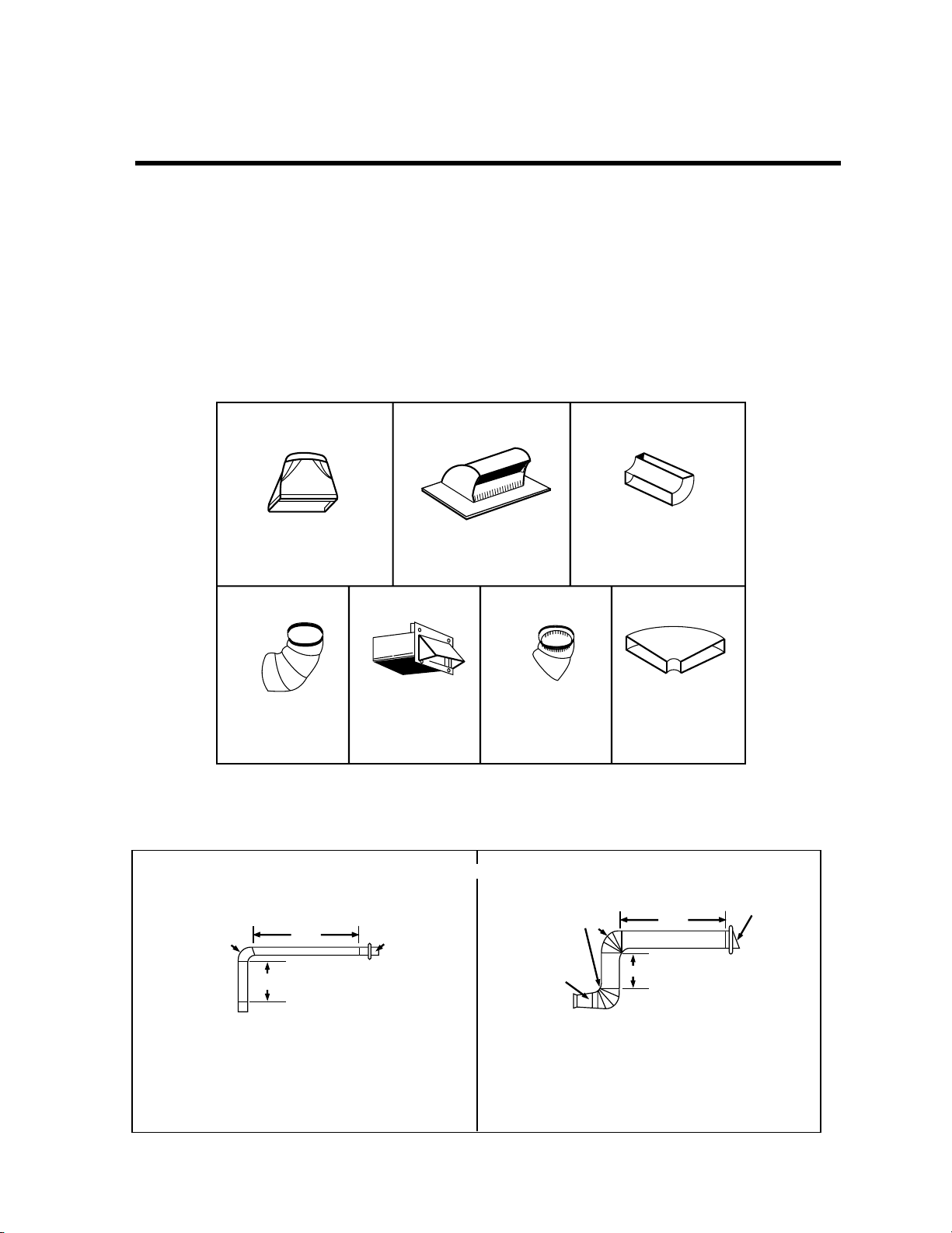
STANDARD FITTINGS
NOTE: If the existing duct is round, you must use a rectangular-to-round adapter, with a rectangular 3" extension
duct installed between the damper assembly and the adapter to prevent the exhaust damper’s sticking.
DUCT LENGTH
The total length of the duct system, including straight duct, elbows, transitions, wall or roof caps must not
exceed the equivalent of 140 feet.
For best performance, do not use more than three 90 degree elbows.
Below are the standard fittings and their equivalent length in feet.
To calculate the equivalent length of each ductpiece used, see the examples below.
9
STEP 3:
Figure 10
A thick, protective
covering
Figure 11
Mounting
plate
Mounting plate
screw(s)
(1 or 2 screws)
Control panel side
Figure 12
Back
of oven
Exhaust
adaptor
WARNING
PREPARE THE VENTING BLOWER
Your microwave oven is shipped with the blower assembled for roof venting. You need to adjust the blower if
you want wall-venting or room-vented (recirculating) installation.
ELECTRICAL SHOCK HAZARD! UNPLUG UNIT BEFORE WORKING ON IT.
• DO NOT PULL OR STRETCH THE BLOWER WIRING! Pulling and stretching the blower wiring could result in
electrical shock.
REMOVE THE MOUNTING PLATE:
1. Remove any shipping materials and parts from inside
the microwave oven.
2. Cover the countertop or cooktop with a thick,
protective covering to protect it from damage and dirt.
See Figure 10.
NOTE: If you have a free-standing range, disconnect it, move it
onto a piece of cardboard or hardboard and pull it away
from the wall, so that you can get closer to the upper
cabinet and back wall for easier measuring and drilling.
3. Remove mounting plate screw(s) (1 or 2 screws)
from the mounting plate as shown and discard
(see Figure 11).
4. This plate will be used to locate and mark the mounting
holes on the rear wall. (It will be used to locate and
mark the mounting holes on the rear wall.)
5. Locate exhaust adaptor, grease filters and hardware
packet.
6. At this point, remove any adhesive tape (if there is any),
on the exhaust adaptor, the grease filters and the
power supply cord.
ROOF-VENTED INSTALLATION:
This oven is shipped assembled for roof-vented. You
will need to install the exhaust adaptor regardless of
cabinet.
1. Attach the exhaust adaptor to the blower plate by
sliding it into the guides (see Figure 12).
Go to step 4 on page 13.
10
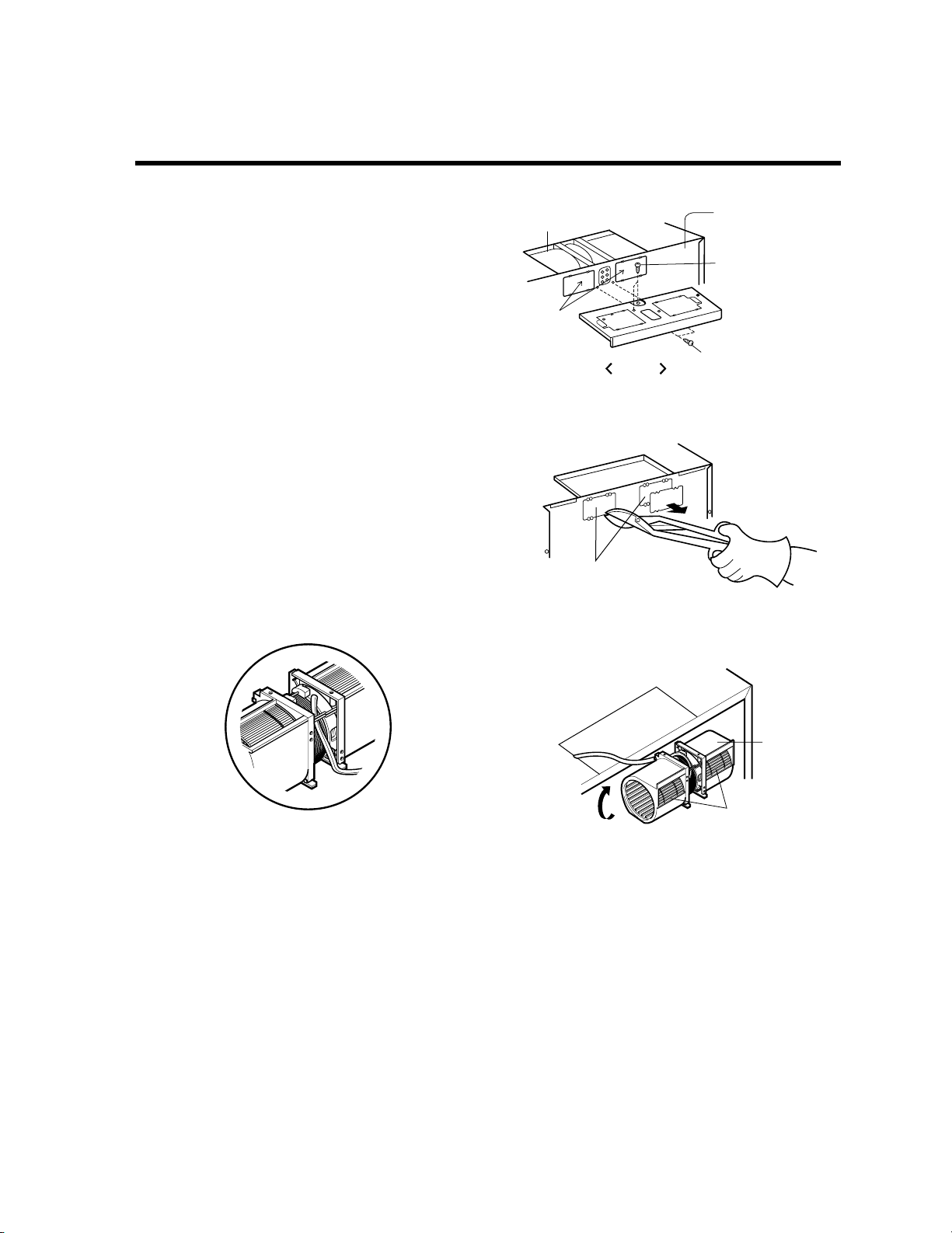
Figure 13
Option
blower plate
mounting screws
blower unit
mounting screw
blower unit
Parts "B"
back plate
Figure 14
Knockout Parts "B"
Parts "B"
Figure 16
exhaust
ports
blower
unit
Figure 15
STEP 3:
PREPARE THE VENTING BLOWER
WALL-VENTED INSTALLATION:
1. Remove one blower unit mounting screw and one blower
plate screw. Remove the blower plate from cabinet.
See Figure 13.
2. Carefully lift the blower unit out of the microwave oven.
3. Use side cutters or tin snips to cut and remove knockouts
“B” from Back plate. Discard knockouts. Be careful not
to distort the plate. See Figure 14.
4. Reassemble the blower wire. See Figure 15.
5. Rotate the unit so that the exhaust ports face the rear of
the cabinet. See Figure 16. When you insert blower unit,
blower wire must be like Figure 16.
6. Place blower unit back into cabinet. Check that the
exhaust ports face towards the rear of the cabinet.
See Figure 17.
7. Reattach the blower plate to cabinet so the exhaust ports
and blower plate opening are aligned. Attach with one
blower unit mounting screw and then one blower plate
mounting screw. See Figure 18.
11

STEP 3:
Figure 19
blower unit
exhaust ports
Figure 18
Figure 21
blower unit
exhaust
ports
Figure 17
blower plate
mounting screws
blower unit
mounting screws
blower plate
mounting screws
blower unit
mounting screws
blower plate
mounting screws
blower unit
mounting screws
Figure 20
blower
unit
Option
Option
Option
PREPARE THE VENTING BLOWER
ROOM-VENTED (Recirculating)
INSTALLATION:
1. Remove one blower unit mounting screw and one
blower plate screw. Remove the blower plate from
cabinet. See Figure 19.
2. Carefully lift the blower unit out of the microwave oven.
3. Rotate blower unit 90˚ so the exhaust ports face the
front of the cabinet. See Figure 20.
4. Place blower unit back into microwave oven.
5. Reattach blower plate to microwave oven. Attach with
the one blower unit mounting screw and then the one
blower plate mounting screw. See Figure 21.
12

Figure 22
Figure 23
upper cabinet template
mounting plate
STEP 4: PREPARE THE WALL AND
UPPER CABINET FOR INSTALLATION
MEASURE AND TACK / TAPE UP THE
TEMPLATES
1. Using a plumb line and (metal) measuring tape, find and
mark the vertical center line on the back wall, as in
Figure 22.
2. Find and mark one or two points where the studs are
on the wall (Studs are normally 16 inches apart) and
then measure and mark the stud locations. If you
cannot find any wall stud, consult a local building
contractor.
CAUTION
DO NOT ATTEMPT TO INSTALL THE MICROWAVE
OVEN IF YOU CANNOT FIND A WALL STUD.
3. Line up the plumb line on the wall with the center line
on the mounting plate.
NOTE: Be sure the minimum width is 30 inches and the
distance from the top of the mounting plate to
the range or counter top is at least 30 inches.
See Figure 4 on page 4.
4. Center mounting plate on rear wall installation area by
lining up the plumb line on wall with centerline on
mounting plate. Make sure the minimum width is 30
inches and that the top of the mounting plate is located a
minimum of 30 inches above the cooking surface. See
Figure 23.
NOTE: If the cabinets are not plumb, adjust the
mounting plate to the cabinets. If the front edge
5. Measure the bottom of the upper cabinet frame. Trim
of the cabinet is lower than the back edge,
adjust the mounting plate to be level with the
cabinet front.
the edges "A" "B" and "C" on the upper cabinet
template so that the template will fit on the bottom of
the upper cabinet. If upper cabinet has a recessed
frame, trim template so that it fits inside the recessed
area. Align the centerline of the upper cabinet template
with the centerline of the mounting plate; then securely
tape or tack the upper cabinet template in place.
See Figure 23
13

STEP 4: PREPARE THE WALL AND
Figure 24
Figure 25
cabinet front
filler block cabinet
bottom shelf
filler
block
WARNING
WARNING
UPPER CABINET FOR INSTALLATION
DRILLING THE HOLES IN THE WALL AND UPPER CABINET:
BE VERY CAREFUL WHEN DRILLING HOLES INTO THE WALL.
Electrical wires could be concealed behind the wall covering
and if the drill hits them you could get an electric shock.
1. Find the points on the mounting plate labeled A, B, C, and D. Drill a 3/16" diameter hole at any of these points that
are in front of a wall stud. Drill a 3/4" diameter hole at any of these points that are over drywall.
2. Drill a 3/8" hole at points J and K on the upper cabinet template.
NOTE: If the bottom of the upper cabinet is recessed 3/4" or more, you will need 2"x2" filler blocks (not included) to
provide additional support for the bolts. See Figure 24.
• Mark the center of each filler block and drill a 3/8" diameter hole at the mark.
• Align filler blocks over the two openings in the top of the microwave oven cabinet and attach to cabinet
with masking tape. See Figure 25.
3. Cut or drill a 2" diameter hole at the area marked M, “power supply cord hole” on the upper cabinet template.
If the upper cabinet is metal, you will need to cover the edge of the hole with the power supply cord bushing
(supplied) to prevent damage to the cord from the rough metal edge.
YOU MUST COVER THE EDGE OF THE POWER SUPPLY CORD HOLE IN
A METAL CABINET WITH THE POWER SUPPLY CORD BUSHING.
FAILURE TO DO SO COULD RESULT IN DAMAGE TO THE CORD AND
ELECTRIC SHOCK.
4. Cut out the venting areas (with the saber saw):
5. Use caulking compound to seal the exterior wall or roof opening around the wall cap or roof cap.
•
Roof-Vented: cut out the shaded area marked L on the upper cabinet template.
•
Wall-Vented: go to STEP 5, INSTALL THE MOUNTING PLATE, located on page 16.
14

Center Line
A
C
B
3/16" Hole on Studs
3/4" Hole on Drywall Only
Draw
Center Line
Draw Lines
on Studs
Wall
Mounting
Plate
Space More Than Wall Thickness
Bolt
End
Toggle Bolt
Toggle Wings
For Wall-
Vented Only
Minimum 66
"
From the Floor
Support Tab Support Tab
E
Mounting
Plate
Figure 26
Figure 27
D
STEP 5:
INSTALL THE MOUNTING
PLATE TO THE WALL
CONNECTING THE OVEN TO A WALL STUD:
NOTE: The oven must be connected to at least one
wall stud.
1. Draw a vertical line on the wall at the center of the 30″
wide space.
Use the mounting plate as the template for the rear
wall. Place the mounting plate on the wall, making sure
that the tabs are against the bottom of the cabinet. Line
up the notch and center line on the mounting plate to
the center line on the wall.
2. While holding the mounting plate with one hand, draw
circles on the wall at holes A, B, C and D. Four holes
must be used for mounting. If the holes are not used,
the installation will not be secure. Installer must use
these holes for proper installation. Use toggle bolts
through these holes unless one of them lines up with a
stud. Use a lag screw for studs.
NOTE: Draw a fifth circle inside area E, through one of
the holes to match the location of a stud.
For wall-vented: The oven requires a rear wall cutout
opening for the rear wall duct and the exhaust adaptor
must be attached to the mounting plate. See the next page
on how to prepare the rear wall cutout opening and the
exhaust adaptor/mounting plate for wall-vented.
3. Drill holes on the circles. If there is a stud, drill a 3/16″
4. Attach the plate to the wall. To use spring toggle head
hole for lag screws. Two or preferably four lag screws
at holes A and C or B and D must be used to secure
mounting plate to wall. If there is no stud, drill a 3/4″
hole for toggle bolts. Make sure to use at least 1 lag
screw at holes of area “E” in a stud, and 4 toggle bolts
at holes A, B, C and D in the drywall or the plaster.
bolts: Remove the toggle wings from the bolts. Insert
the bolts into the mounting plate and replace the spring
toggle head to 3/4″ past the bolt ends. Insert the spring
toggle head into the holes in the wall to mount the
bracket. You may pull forward on the bracket to help in
tightening the toggle bolts. Tighten all bolts.
See Figure 27.
15

STEP 5:
Slide exhaust
adaptor into
guides on
rear panel.
Exhaust Adaptor
Damper
(hinge side up)
Locking
Tabs
Guides
Mounting Plate
(wall side)
Figure 28
Figure 29
INSTALL THE MOUNTING
PLATE TO THE WALL
TO PREPARE THE REAR WALL
CUTOUT OPENING AND EXHAUST
ADAPTOR/MOUNTING PLATE FOR
WALL-VENTED:
1. Place the mounting plate against the rear wall as
described in step 5 item 1 (page 15).
2. Using a pencil, put dots through slots F and G, and
through holes H and I. Remove the mounting plate and
draw lines extending through the points. This will give
the location and size of the box cutout for the rear wall
duct. See Figure 28.
• Attach the exhaust adaptor to the rear mounting plate by
sliding it into the guides at the top center of the plate on
the wall side. Push in securely until it is past the top
locking tabs and in the lower locking tabs. Take care to
assure the damper hinge is installed so that it is at the
top and that the damper swings freely.
• Carefully guide the exhaust adaptor (now attached to the
mounting plate) into the house duct, before using the
screws to attach the plate to the wall. This will assure
proper alignment for installation. See Figure 29.
• Return to step 5, item 3 (page 15) to continue. After
completing the installation of the mounting plate, again
check the rear damper for free movement to assure it
will operate properly.
16

STEP 6:
Figure 30
Figure 31
power cord
power cord
hole
WARNING
ATTACH THE OVEN TO THE WALL
You will need two people to lift this
microwave. Failure to use more
than one person could result in
personal injury.
1. Carefully lift microwave oven and hang it on support
tabs (See Figure 26 on the page 15) at the bottom
of the mounting plate. Reaching through upper
cabinet, thread power supply cord through the
power supply cord hole in the bottom of the upper
cabinet.
See Figure 30.
2. Rotate the microwave oven upward so the top of
oven is against the bottom of the upper cabinet or
cabinet frame.
3. Insert a bolt down through each hole in the upper
cabinet bottom. See Figure 31.
Tighten the bolts until the gap between the upper
cabinet and microwave oven is closed.
4. If wall vented or room vented installation is used, go
to No.7 on the next page.
17

STEP 6:
Figure 32
Figure 34
damper
duct
power
supply
cord
clamp
Figure 33
ATTACH THE OVEN TO THE WALL
5. Roof vented installation: See Figure 32
Install ductwork through the vent opening in the upper
cabinet. Complete the venting system through the roof
according to the method needed.
See “PREPARE THE VENTING SYSTEM,” step 2 on
the page 8. Use caulking to seal exterior roof opening
around the exhaust cap. See Figure 6 on page 8.
6. Use power supply cord clamp to bundle the power
supply cord. Install the power supply cord clamp, using
a screw as shown in Figure 33, to inside of the cabinet.
7. To install the grease filter: Slide it into the slide slot,
then push up and toward oven center to lock.
See Figure 34.
8. Plug in the power supply cord.
9. Read your use and care manual, then check the
operation of your microwave oven.
18

Électroménagers
Four à micro-ondes avec hotte
Instructions d’installation
For Models: HMV9302, HMV9303, HMV9305, HMV9306, HMV9307
PRIÈRE DE LIRE TOUTES LES INSTRUCTIONS AVANT DE PROCÉDER À L’INSTALLATION.
IMPORTANT : Conserver ces instructions pour que l’inspecteur local puisse vérifier l’installation.
INSTALLATEUR : Prière de remettre ces instructions au propriétaire après l’installation.
PROPRIÉTAIRE : Conserver ces instructions pour référence future.
Imprimé en Corée
Piéce n°: 3828W5U0503
Household Appliances

2
VOTRE SÉCURITÉ D’ABORD
AVANT DE COMMENCER
• L’installateur est responsable de faire une installation adéquate!
– Lire le manuel au complet avant de commencer. L’étiquette portant le numéro de modèle se trouve sur le devant
du four. Voir figure 1.
AVERTISSEMENT
POUR VOTRE SÉCURITÉ :
•
Il faut deux personnes pour installer ce four. Il est lourd et peut entraîner des blessures corporelles s’il n’est pas
manipulé adéquatement. Les dimensions du four sont :
Hauteur : 16 7/16 po (417 mm)
Largeur : 29 15/16 po (760 mm)
Profondeur : 15 5/8 po (397 mm)
Poids : 60 lb (27,25 kg)
• Éviter les chocs électriques!
– Avant de percer le mur, noter l’emplacement des prises de courant et où des fils électriques pourraient être
dissimulés derrière la paroi. IL Y A DES RISQUES D’ÉLECTROCUTION si l’on touche à des fils électriques
avec la mèche de la perceuse.
– Trouver le disjoncteur ou le fusible correspondant et couper le courant aux circuits électriques qui pourraient
être affectés par l’installation de ce four. IL Y A DES RISQUES D’ÉLECROCUTION SI LE COURANT
N’EST PAS COUPÉ.
• ALIMENTATION ÉLECTRIQUE DE CE FOUR : 120 V CA 60 Hz.
– Il faut une alimentation électrique DISTINCTE de 120 V, 60 Hz, CA seulement de 15 ou 20 A, avec fusible
ou disjoncteur (située dans l’armoire au dessus du four à micro-ondes, le plus près possible du four) servant
uniquement à alimenter le four à micro-ondes.
La plaque de montage se trouve à l’arrière du four à micro-ondes. Voir figure 2.
S’ASSURER DE BIEN LIRE LES DIRECTIVES DE SÉCURITÉ QUI SUIVENT :
Étiquette de numéro de modèle
Plaque de
montage
(La déposer
du four avant
l’installation)
Arrière du four
Figure 1 Figure 2

3
VOTRE SÉCURITÉ D’ABORD
• CET ÉLECTROMÉNAGER DOIT ÊTRE MIS À LA TERRE!
– Dans le cas d’un court-circuit, la mise à la terre réduit le risque d’électrocution en fournissant un fil de fuite pour
le courant électrique. Cet électroménager est muni d’un fil contenant un fil et une broche de mise à la terre.
• Insérer la fiche dans une prise correctement installée et mise à la terre. Voir figure 3.
• Ne pas utiliser de rallonge.
• Garder le fil au sec, sans le pincer ni l’écraser!
• NE JAMAIS, EN AUCUNE CIRCONSTANCE, ENLEVER
LA BROCHE DE MISE À LA TERRE DU FIL D’ALIMENTATION!
Cet électroménager DOIT être mis à la terre.
AVERTISSEMENT
Si la fiche de mise à la terre n’est pas correctement utilisée, il y a risque
d’électrocution.
– S’adresser à un électricien qualifié en cas de doute que le four à micro-ondes est correctement mis à la terre ou
si les instructions de mise à la terre ne sont pas parfaitement comprises.
NE PAS UTILISER DE FUSIBLE SUR LE NEUTRE OU DANS LE CIRCUIT DE MISE À LA TERRE.
AVERTISSEMENT
Une mauvaise mise à la terre peut entraîner une électrocution ou d’autres
blessures!
CONSERVER CES INSTRUCTIONS POUR L’INSPECTEUR DE BÂTIMENTS LOCAL.
• ÉVITER L’EXPOSITION EXCESSIVE AUX MICRO-ONDES!
– NE PAS tenter d’utiliser le four à micro-ondes avec la porte ouverte.
– NE PAS tenter de contourner les dispositifs de sécurité.
– NE PAS placer d’objet entre le devant du four et la porte.
– NE PAS laisser de saleté ou de nettoyant s’accumuler sur les surfaces planes du devant et de la porte du four.
– NE PAS utiliser le four à micro-ondes s’il est endommagé.
– La porte du four doit se fermer complètement pour pouvoir utiliser le four en sécurité.
– NE PAS UTILISER LE FOUR À MICRO-ONDES SI :
• la porte est tordue;
• les charnières ou le loquet sont endommagés ou lâches;
• les joints d’étanchéité ou la vitre sont craquelés ou cassés.
– NE PAS TENTER DE RÉGLER OU DE RÉPARER LE FOUR À MICRO-ONDES SOI-MÊME!
Les réparations et réglages devraient être confiés à un technicien spécialisé qui peut vérifier s’il y a des fuites
de micro-ondes après avoir réparé le four.
AVERTISSEMENT
Si le four à micro-ondes n’est pas utilisé conformément aux instructions, il
peut en résulter une exposition excessive aux micro-ondes.
PRISE DE COURANT POLARISÉE
ET MISE À LA TERRE
Fiche à trois broches (mise à la terre)
Figure 3

4
4
VOTRE SÉCURITÉ D’ABORD
• S’ASSURER D’AVOIR SUFFISAMMENT D’ESPACE ET DE SUPPORT
– Monter le four sur un mur vertical et plat afin qu’il soit soutenu par le mur. Le mur doit être construit avec des
poutres de 2x4 po en bois au moins et du placoplâtre de 3/8 po (10 mm) où du plâtre et des lattes.
– VISSER AU MOINS UN des deux tire-fond soutenant le four dans une poutre verticale de 2 x 4 po.
– NE PAS monter le four sur une armoire d’un îlot de cuisine ou d’une péninsule.
– S’ASSURER que la structure de l’armoire et du mur peuvent supporter 150 lb (68 kg), ainsi que le poids de
tout ce qui est placé dans l’armoire et le four à micro-ondes.
– Placer le four hors des courants d’air forts, tels que les fenêtres, portes ou bouches de ventilation puissantes.
– S’ASSURER d’avoir suffisamment d’espace. Voir la Figure 4 ci-dessous pour connaître les dégagements
verticaux et horizontaux minimums.
MISE EN GARDE
Si le four à micro-ondes n’est pas monté selon les instructions, il y a des
risques de blessures et/ou de dommages.
MISE EN GARDE
• Avant de commencer l’installation du four, PLACER UN MORCEAU DE CARTON OU D’AUTRE MATÉRIAU
ÉPAIS (tel qu’une couverture) sur le comptoir ou la cuisinière pour les protéger. Ne pas utiliser de plastique.
Tout défaut de protéger ces surfaces pourrait entraîner des dommages.
Prise de courant mise
à la terre
(dans l’armoire supérieure)
Trou du fil d’alimentation
Ouverture d’au moins 760 mm
(30 po) de largeur
Hauteur minimum de 760 mm
(30 po) entre le dessous de
l’armoire et le dessus de la cuisinière ou du comptoir
(Utiliser les gabarits inclus avec les
instructions d’installation)
Figure 4

5
PIÈCES, OUTILS ET MATÉRIAUX
• LES PIÈCES SUIVANTES SONT FOURNIES AVEC LE FOUR
REMARQUE : Selon les exigences d’évacuation, certaines pièces pourraient ne pas être utilisées
REMARQUE : Il faut installer au moins un tire-fond dans une poutre de 2 x 4 et les quatre boulons
à ailettes dans le mur. Il faut également que la surface de montage réponde à l’exigence de pouvoir soutenir un poids de 150 lb (68 kg).
centerline
6"
4"
8"
12"
10-
8-
11
Roof-venting installation
Upper-cabinet template
B
C
D
10-
3
16
Registre/connecteur de conduit
(pour évacuation par le toit ou le mur)
Pas grandeur réelle
Une bride d’attache de fil d’alimentation
et une vis de couleur foncée
(pour retenir le fil d’alimentation)
Grandeur réelle
Coussinet de retenue du fil d’alimentation - Grandeur réelle (pour le trou du fil dans une armoire en métal)
Quatre tire-fond de 1/4 po x
Grandeur réelle
(pour les poutres du mur)
Deux boulons de 1/4 po x 3 po (6,5 x 76 mm) -
Grandeur réelle (pour visser dans l’armoire supérieure)
2 po (6,5 x 50 mm) -
Quatre boulons à ailettes de 1/4 po x 3 po
(6,5 x 76 mm) - Grandeur réelle
(pour les trous dans le placoplâtre)
Deux vis autotaraudeuses - Grandeur réelle
(pour visser le registre/connecteur de conduit)
OU
Un gabarit pour l’armoire supérieure-
Pas grandeur réelle
Quatre écrous à ailettes - Grandeur réelle
(pour les boulons à ailettes)

6
PIÈCES, OUTILS ET MATÉRIAUX
LES OUTILS ET MATÉRIAUX SUIVANTS SONT REQUIS POUR L’INSTALLATION :
Du carton ou autre matériau épais pour couvrir le comptoir
• S’il faut percer un mur de brique ou de maçonnerie, il faudra des outils et de la quincaillerie spéciaux.
• Les conduits nécessaires pour l’installation ne sont pas compris. Tous les couvercles muraux ou de toit doivent
inclurent un registre anti-refoulement (illustré à la page 5).
Ruban adhésif transparent
(pour fixer le gabarit à l’armoire)
Détecteur de poutre ou clou mince
Scie sauteuse (pour découper
le trou d’evacuation par le toit
ou le mur)
Scie à guichet (pour le trou du fil d’alimentation
dans l’armoire)
Perceuse électrique
Mèches à bois de 3/8 et de
3/4 po (10 mm et 19 mm)
Forets de 1/2 et de
3/16 po (13 mm et
5 mm)
Tournevis Phillips
Crayon
Tournevis à lame plate
Ruban à mesurer (métallique de préférence)
Pinces coupantes ou cisailles à tôles
Pistolet à calfeutrer
Niveau de maçon
Ruban à conduit
Gants

7
ÉTAPE 1 : PRÉPARATION
DES CONNEXIONS ÉLECTRIQUES
AVERTISSEMENT
ÉVITER LES RISQUES D’ÉLECTROCUTION! CET ÉLECTROMÉNAGER DOIT
ÊTRE MIS À LA TERRE!
1. Placer une prise de courant mise à la terre pour cet électroménager
dans l’armoire au-dessus du four tel que montré dans la Figure 4
(Détail)
REMARQUE : La prise doit être sur un circuit distinct pour le four à
micro-ondes de 120 V, 60 Hz avec un fusible de 15
ou de 20 A.
IMPORTANT : S’il n’y a pas de prise murale appropriée, il faut en
faire installer une par un électricien qualifié.
2. Le trou pour le fil d’alimentation (montré dans la Figure 4 (Détail))
sera découpé plus tard lors de la préparation du mur et de l’armoire
supérieure à l’étape 4.
REMARQUE : Ne pas utiliser de rallonge.
Garder le fil d’alimentation au sec, sans le pincer ni l’écraser.
AVERTISSEMENT
Une mauvaise mise à la terre peut entraîner une électrocution ou d’autres
blessures!
• NE JAMAIS, EN AUCUNE CIRCONSTANCE, ENLEVER LA BROCHE DE MISE À LA TERRE DU FIL
D’ALIMENTATION! Cet électroménager DOIT être mis à la terre!
Prise mise à
la terre
(à l’intérieur
de l’armoire)
Armoire
supérieure
Trou du fil d’alimentation
Figure 4 Détail

8
ÉTAPE 2 :
PRÉPARATION DU SYSTÈME D’ÉVACUATION
AVERTISSEMENT : RISQUE D’INCENDIE
CE FOUR DOIT ÊTRE ADÉQUATEMENT ÉVACUÉ!
L’évacuation de ce four peut être faire de trois manières :
Évacuation par le toit : Si le four est situé sur un mur extérieur près du toit comme dans les figures 5
(conduit de 3 1/4 po x 10 po (83 x 254 mm)) et 6 (conduit rond de 6 po (152 mm)).
Évacuation par le mur : Si le four est situé sur un mur extérieur au rez-de-chaussée de la maison, comme
dans les figures 7 (conduit de 3 1/4 po x 10 po (83 x 254 mm)) et 6 (conduit rond
de 6 po (152 mm)).
Évacuation dans la pièce : Si le four est situé sur un mur intérieur de la maison, comme dans la Figure 8.
REMARQUE : Si l’on choisit l’évacuation arrière (par le toit ou le mur), il faut s’assurer qu’il y a suffisamment
d’espace dans le mur pour le conduit d’évacuation.
CHOSES À SE RAPPELER LORS DE L’INSTALLATION DES CONDUITS :
• Garder la longueur des conduits et le nombre de raccords au minimum pour évacuer le four efficacement. Voir les
exemples à la page 9.
• Garder les conduits de la même dimension.
• Ne pas installer deux coudes ensembles.
• Utiliser du ruban à conduit pour sceller tous les joints du système.
• Calfeutrer l’ouverture autour du couvercle extérieur sur le mur ou le toit.
REMARQUE : Les conduits nécessaires pour l'évacuation vers l'extérieur ne sont pas fournis avec le four à
micro-ondes. Les raccords standards et leur équivalence de longueur sont montrés dans la
Figure 9 à la page 9.
Évacuation par le mur
À travers le mur
Couvercle
mural
Conduit
3 1/4 x 10 po
(83 x 254 mm)
Figure 7
Armoire
Four
À travers le toit
Conduit de
3 1/4 x 10 po
(83 x 254 mm)
Figure 5
Couvercle de toit
Évacuation par le toit
Armoire
Four
Conduit
rond de 6 po
(152 mm)
diam. minimum
Transition de
3 1/4 po (83 mm)
à conduit rond
Transition de 3 1/4 po
(83 mm) à conduit rond
Figure 6
Couvercle de toit
Couvercle
mural
Coude
« Évacuation dans la pièce »
Figure 8
Armoire
Four
« Évacuation par le mur »
« Évacuation par le toit »

9
ÉTAPE 2 :
PRÉPARATION DU SYSTÈME D’ÉVACUATION
RACCORDS STANDARD
REMARQUE : Si les conduits existants sont rond, il faut utiliser un adaptateur rectangulaire à rond, avec
une rallonge rectangulaire de 3 po (75 mm) installée entre l’assemblage de registre et
l’adaptateur pour empêcher le registre de rester accroché.
LONGUEUR DES CONDUITS
La longueur totale du système de conduits, y compris les tuyaux droits, les coudes, les transitions et les
couvercles muraux ou de toit ne doivent pas dépasser l’équivalent de 140 pi (42 m).
Pour le meilleur rendement, ne pas utiliser plus de trois coudes à 90 degrés.
Voici des raccords standard et leur longueur équivalente.
Pour calculer la longueur équivalente de chaque pièce de conduit utilisé, voir les exemples ci-dessous.
Figure 9
1
4567
23
(83 x 254 mm) à 6 po
(152 mm) = 5 pi (1,5 m)
Coude 90°
= 10 pi (3 m)
Coude 45°
= 5 pi (1,5 m)
Couvercle mural
3 1/4 x 10 po
= 40 pi (12 m)
Coude plat
3 1/4 x 10 po
= 10 pi (3 m)
Couvercle de toit
3 1/4 x 10 po (83 x 254 mm)
3 1/4 x 10 po (83 x 254 mm)
= 25 pi (7,5 m)
3 1/4 x 10 po
= 24 pi (7,2 m)
Coude 90°
(83 x 254 mm)
(83 x 254 mm)
Exemples
Pour les systèmes de 3 1/4 x 10 po
1-Couvercle mural
2,4 m (8 pi) de tuyau droit
LONGUEUR TOTALE
6 pi
2 pi (60 cm)
Coude 90°
Couvercle mural
= 25 pi (7,5 m)
3 1/4 x 10 po
(83 x 254 mm)
(1,8 m)
1 Coude 90° 3 1/4 x 10 po
(83 x 254 mm)
= 40 pi (12,0 m)
= 8 pi (2,4 m)
= 73 pi (21,9 m)
1-Transition
2-Coudes 90°
1-Couvercle mural
2,4 m (8 pi) de tuyau droit
LONGUEUR TOTALE
Pour les systèmes ronds de 6 po
2 pi (60 cm)
6 pi
Transition
Couvercle
mural
= 5 pi (1,5 m)
= 20 pi (6,0 m)
= 40 pi (12,0 m)
= 8 pi (2,4 m)
= 73 pi (21,9 m)
(1,8 m)
Coudes 90°

10
ÉTAPE 3 : PRÉPARATION DU VENTILATEUR
D’ÉVACUATION
RISQUE D’ÉLECTROCUTION! DÉBRANCHER L’APPAREIL AVANT DE FAIRE
DES TRAVAUX.
• NE PAS TIRER OU ÉTIRER LE CÂBLAGE DU VENTILATEUR! Tirer ou étirer le câblage du ventilateur peut
entraîner l'électrocution.
ENLEVER LA PLAQUE DE MONTAGE :
1. Retirer les matériaux d’emballage et les pièces de l’intérieur du
four à micro-ondes.
2. Couvrir le comptoir ou la cuisinière avec une protection
épaisse pour les protéger des dommages et de la saleté.
Voir la Figure 10.
REMARQUE : Si la cuisinière est autoportante, la débrancher
et la placer sur un morceau de carton ou un
panneau pour l'éloigner du mur et permettre de
s'approcher de l'armoire supérieure et du mur
afin de mesurer et de percer facilement.
3. Retirer les vis (1 ou 2) de la plaque de montage tel qu’illustré et
les jeter. (Voir la Figure 11.)
4. Cette plaque servira à localiser et percer les trous de
montage sur le mur.
5. Trouver l’adaptateur d’évacuation, les filtres à graisse et
le fil d’alimentation.
6. À ce point, retirer tout ruban adhésif (si présent) qui se
trouve sur l'adaptateur d'évacuation, les filtres à graisse
et le fil d'alimentation.
INSTALLATION À ÉVACUATION
PAR LE TOIT :
Ce four est fourni avec le ventilateur assemblé pour
l’évacuation par le toit. Il faut installer l’adaptateur
d’évacuation peu importe le boîtier.
1. Fixer l’adaptateur sur la plaque du ventilateur en le
glissant dans les guides (voir Figure 12).
2. Aller à l’étape 4 de la page 13.
Le four à micro-ondes est fourni avec le ventilateur assemblé pour l’évacuation par le toit. Il faut faire des
ajustements pour l’évacuation par le mur ou dans la pièce (recirculation).
Figure 12
Arrière
du four
Adapteur
d’évacuation
Figure 10
Figure 11
Plaque de
montage
Vis de la plaque
de montage
(1 ou 2 vis)
Côté du panneau de commande
Couverture protectrice
épaisse
AVERTISSEMENT

11
ÉTAPE 3 : PRÉPARATION DU VENTILATEUR
D’ÉVACUATION
Figure 13
Vis de montage de la
plaque de ventilateur
Vis de montage
du ventilateur
Ventilateur
Pièces « B »
Plaque arrière
Figure 14
Panneaux
défonçables « B »
Pièces « B »
Figure 16
Évents
Ventilateur
Figure 15
INSTALLATION À ÉVACUATION PAR LE
MUR :
1. Retirer une vis de montage du ventilateur et une vis de
la plaque du ventilateur, retirer la plaque du boîtier.
Voir la Figure 13.
2. Soigneusement soulever le ventilateur et le retirer du
four à micro-ondes.
3. À l’aide de pinces coupantes ou de cisailles, découper
et enlever les panneaux défonçables « B » de la
plaque arrière et les jeter. Prendre soin de ne pas
tordre la plaque. Voir la Figure 14.
4. Remonter le fil du ventilateur. Voir la Figure 15.
5. Retourner le ventilateur afin que les évents soient
tournés vers l’arrière du boîtier. Voir Figure 16. Lors
de l’insertion du ventilateur, le fil doit être dans une
position comme celle illustrée dans la Figure 16.
6. Replacer le ventilateur dans le boîtier. Vérifier que les
évents sont tournés vers l'arrière du boîtier. Voir la
Figure 17.
7. Remonter la plaque du ventilateur sur le boîtier de
manière à ce que les évents et l’ouverture dans la
plaque de ventilateur soient alignés. La fixer avec une
vis de montage du ventilateur puis une vis de montage
de la plaque de ventilateur. Voir la Figure 18.
Option

12
ÉTAPE 3 : PRÉPARATION DU VENTILATEUR
D’ÉVACUATION
Figure 19
Évents du
ventilateur
Figure 18
Figure 21
Ventilateur
Évents
Figure 17
Vis de montage de la
plaque de ventilateur
Vis de montage
du ventilateur
Vis de montage de la
plaque de ventilateur
Vis de montage
du ventilateur
Vis de montage de la
plaque de ventilateur
Vis de montage
du ventilateur
Figure 20
Ventilateur
INSTALLATION À ÉVACUATION
DANS LA PIÈCE (Recirculation) :
1. Retirer une vis de montage du ventilateur et une vis
de la plaque du ventilateur, retirer la plaque du boîtier.
Voir la Figure 19.
2. Soigneusement soulever le ventilateur et le retirer du
four à micro-ondes.
3. Retourner le ventilateur de 90° afin que les évents
soient tournés vers l’avant du boîtier. Voir la Figure 20.
4. Replacer le ventilateur dans le boîtier du four à microondes.
5. Remonter la plaque du ventilateur sur le boîtier. La
fixer avec une vis de montage du ventilateur puis une
vis de montage de la plaque de ventilateur. Voir la
Figure 21.
Option
Option
Option

13
ÉTAPE 4 : PRÉPARATION DU MUR ET DE
L’ARMOIRE SUPÉRIEURE POUR L’INSTALLATION
MESURER ET FIXER LES GABARITS
AVEC DU RUBAN OU DES PUNAISES
1. Utiliser un niveau de maçon et un ruban à mesurer
(métallique) pour trouver et marquer la ligne verticale
centrale sur le mur tel qu'illustré dans la Figure 22.
2. Trouver et marquer un ou deux points où les poutres se
trouvent. (En règle générale, les poutres sont placées à
intervalles de 16 po (406 mm).) Mesurer et marquer
ensuite l’emplacement des poutres. S’il est impossible de
trouver des poutres, consulter un contracteur local.
3. Aligner la ligne centrale marquée sur le mur avec le centre de
la plaque de montage.
REMARQUE : S’assurer qu’il faut une largeur minimum de
30 po (760 mm) et que le haut de la plaque
est à au moins 30 po (760 mm) du dessus
de la cuisinière ou du comptoir. Voir Figure 4
à la page 4.
4. Centrer la plaque de montage dans l'aire de montage sur le
mur en alignant la ligne verticale centrale à l'équerre avec la
ligne centrale de la plaque de montage. Il faut une largeur
minimum de 30 po (760 mm) et que le haut de la plaque soit
à au moins 30 po (760 mm) de la surface de cuisson. Voir
Figure 23.
REMARQUE : Si les armoires ne sont pas à niveau, ajuster
la plaque de montage en fonction des
armoires. Si l’avant de l’armoire est plus bas
que l’arrière, ajuster la plaque de montage
afin qu'elle soit de niveau avec l'avant de
l'armoire.
5. Mesurer le fond du cadre de l'armoire supérieure. Découper
les rebords A, B et C du gabarit de l'armoire supérieure afin
que le gabarit puisse être placé sous le fond de l’armoire. Si
l’armoire à un cadre renfoncé, découper le gabarit afin qu’il
s'ajuste à la section renfoncée. Aligner la ligne centrale du
gabarit avec la ligne centrale de la plaque de montage. Fixer
ensuite le gabarit solidement avec du ruban adhésif ou des
punaises. Voir la Figure 23.
MISE EN GARDE
NE PAS TENTER D’INSTALLER LE FOUR À
MICRO-ONDES S’IL EST IMPOSSIBLE DE TROUVER
UNE POUTRE.
Figure 22
Figure 23
Gabarit de l’armoire supérieure
Plaque de montage

14
ÉTAPE 4 : PRÉPARATION DU MUR ET DE
L’ARMOIRE SUPÉRIEURE POUR L’INSTALLATION
PERÇAGE DES TROUS DANS LE MUR ET L’ARMOIRE SUPÉRIEURE
AVERTISSEMENT
PRENDRE GARDE LORS DU PERÇAGE DES TROUS DANS LE MUR.
Des fils électriques peuvent être dissimulés derrière la paroi du mur et si la mèche y
touche, il y un risque d’électrocution.
AVERTISSEMENT
DANS LE CAS D’UNE ARMOIRE EN MÉTAL, IL FAUT COUVRIR LE REBORD DU TROU DU
FIL D’ALIMENTATION AVEC LE COUSSINET DE FIL D’ALIMENTATION. SI CE N'EST PAS
FAIT, LE FIL POURRAIT ÊTRE ENDOMMAGÉ ET CAUSER DES RISQUES D'ÉLECROCUTION.
1. Trouver sur la plaque de montage les points marqués A, B, C et D. Percer un trou de 3/16 po (5 mm) à chacun
de ces points qui se trouve sur une poutre. Percer un trou de 3/4 po (19 mm) à chacun de ces points qui se trouve
sur du placoplâtre.
2. Percer un trou de 3/8 po (10 mm) au points J et K du gabarit de l’armoire supérieure.
REMARQUE : Si le fond de l’armoire est renfoncé de plus de 3/4 po (19 mm) ou plus, il faudra installer des
fourrures de 2 x 2 po (50 x 50 mm) (non comprises)afin de donner un support additionnel
aux boulons. Voir la Figure 24.
• Marquer le centre de chaque fourrure et percer un trou de 3/8 po (10 mm) sur la marque.
• Aligner les fourrures sur les deux ouvertures sur le dessus du boîtier du four à micro-ondes
et les fixer avec du ruban à masquer. Figure 25.
3. Découper ou percer un trou de 2 po (50 mm) à l’emplacement marqué M sur le gabarit de l'armoire supérieure,
pour le fil d’alimentation.
4. Découper le trou pour l’évent (avec la scie sauteuse) :
•Évacuation par le toit : découper la section ombragée marquée L sur le gabarit de l’armoire supérieure.
•Évacuation par le mur : passer à l’Étape 5, Installation de la plaque de montage, à la page 16.
5. Utiliser du calfeutrage pour sceller l'ouverture dans le mur extérieur ou dans le toit autour du couvercle de toit ou
mural.
Figure 24
Figure 25
Devant de l’armoire
Fourrure Fond de
l’armoire
Fourrure

15
ÉTAPE 5 : INSTALLATION DE LA PLAQUE DE
MONTAGE SUR LE MUR
ATTACHER LE FOUR À UNE POUTRE MURALE :
REMARQUE : Le four doit être soutenu par au
moins une poutre.
1. Marquer une ligne verticale sur le mur au centre de
l’aire de 30 po (760 mm).
Utiliser la plaque de montage comme gabarit pour
le mur. Placer la plaque sur le mur en s’assurant que
les languettes reposent contre le fond de l’armoire.
Aligner la coche et la ligne centrale de la plaque
avec la ligne centrale marquée sur le mur.
2. En tenant la plaque contre le mur avec une main,
dessiner des cercles sur le mur aux emplacements
A, B, C et D. Les quatre trous doivent servir pour
le montage. Si tous les trous ne sont pas utilisés,
l’installation ne sera pas sécuritaire. L’installateur doit
utiliser ces trous pour faire une installation adéquate.
Utiliser les boulons à ailettes dans ces trous à moins
qu’un d’entre eux s’aligne avec une poutre. Pour les
poutres, utiliser les tire-fond.
REMARQUE : Dessiner un cercle dans un des
trous de l’aire E correspondant à
l’emplacement d’une poutre.
Pour l’évacuation par le mur : Il faut découper un
trou dans le mur pour les conduits d’évacuation et
l’adaptateur d’évacuation doit être posé sur la plaque
de montage. Voir la page suivante pour savoir comment
préparer le mur et l’adaptateur sur la plaque de montage pour l’évacuation par le mur.
3. Percer des trous dans les cercles. S’il y a une
poutre, percer un trou de 3/16 po (5 mm) pour les
tire-fond. Il faut utiliser deux et préférablement quatre
tire-fond dans les trous A, B, C et D pour fixer la
plaque au mur. S'il n'y a pas de poutre, percer des
trous de 3/4 po (19 mm) pour les boulons à ailettes.
S’assurer de visser au moins un tire-fond dans les
trous de l'aire E dans une poutre et 4 boulons à
ailettes aux trous A, B, C et D dans le placoplâtre ou
le plâtre.
4 Fixer la plaque au mur. Pour utiliser les boulons à
ailettes, retirer les ailettes du boulon, passer le
boulon dans le trou de la plaque de montage et
revisser les ailettes sur le boulon jusqu’à 3/4 po
(19 mm) de l’extrémité du boulon. Insérer les ailettes
dans le trou dans le mur pour monter la plaque. Tirer
sur la plaque pour serrer le boulon plus facilement.
Serrer tous les boulons. Voir la Figure 27.
Ligne centrale
A
C
B
Trou de 3/16 po (5 mm)
pour les poutres
Marquer
une ligne centrale
Marquer les
poutres d’une ligne
Mur
Plaque de
montage
Espace plus grand que l’épaisseur du mur
Extrémité
du boulon
Boulon à
Ailettes
Pour
le mur seulement
Minimum de 66 po
(1676 mm)
Languette de support Languette de support
E
Plaque de
montage
Figure 26
Figure 27
D
du plancher
Trou de 3/4 po (19 mm)
pour le placoplâtre seulement
évacuation par
ailettes

1616
ÉTAPE 5 : INSTALLATION DE LA PLAQUE DE
MONTAGE SUR LE MUR
1. Placer la plaque de montage contre le mur arrière tel
que décrit au numéro 1 de l’Étape 5 (page 15).
2. À l’aide d’un crayon, faire des points dans les fentes F
et G ainsi que dans les trous H et I. Retirer la plaque
de montage et tracer des lignes pour relier les points.
Ceci donne les dimensions et la position du découpage de la boîte de conduit arrière. Voir figure 28.
• Fixer l’adaptateur d’évent à la plaque de montage en
le glissant dans les guides au centre supérieur de la
plaque, du côté du mur. Pousser jusqu'à ce qu'il
franchisse les languettes de blocage supérieures et
soit solidement enfoncé dans les languettes de blocage inférieures. S'assurer que les charnières du
registre de l'évent sont vers le haut et que le registre
d'ouvre sans obstruction.
• Guider soigneusement l’adaptateur d’évent (maintenant fixé sur la plaque de montage) dans le conduit
de la maison avant d’utiliser les vis pour fixer la plaque
au mur. Ceci assurera un alignement adéquat pour
l'installation. Figure 29.
• Revenir à l’étape 5, numéro 3 (page 15) pour continuer. Après avoir complété l’installation, vérifier que
le registre bouge librement pour s’assurer qu’il fonctionnera correctement.
PRÉPARATION DE L’OUVERTURE
D’ÉVACUATION ET DE
L’ADAPTATEUR/PLAQUE DE
MONTAGE POUR L’ÉVACUATION
PAR LE MUR.
Glisser
l’adaptateur
d’éven dans les
guides à l’arrière
Adapteur d’évent
Registre
(charnière
Languettes
de blocage
Guides
Plaque de montage
(côté vers le mur)
Figure 28
Figure 29
de la plaque.
vers le haut)

17
ÉTAPE 6 :
FIXER LE FOUR AU MUR
1. Soigneusement soulever le four à micro-ondes et
l’accrocher sur les languettes de support (voir la
Figure 26 à la page 15) dans la bas de la plaque de
montage. En passant par l’armoire supérieure, passer
le fil d’alimentation à travers le fond de l’armoire. Voir
la Figure 30.
2. Pivoter le four à micro-ondes vers le haut afin que le
dessus du four repose contre le dessous de l’armoire
ou de son cadre.
3. Insérer un boulon dans chaque trou dans le fond de
l’armoire. Voir la Figure 31.
Serrer les boulons jusqu’à ce que l’espace entre
l’armoire et le four à micro-ondes soit éliminé.
4. Si l'évacuation est faite par le mur ou dans la pièce,
aller au numéro 7 à la page suivante.
Il faut deux personnes pour soulever
ce four à micro-ondes. Une seule
personne essayant de soulever le four
à micro-ondes pourrait se blesser.
AVERTISSEMENT
Figure 30
Figure 31
Fil d’alimentation
Trou pour le
fil d’alimentation

18
ÉTAPE 6 :
FIXER LE FOUR AU MUR
Figure 32
Figure 34
Registre
duct
Bride
de fil
d’alimentation
Figure 33
5. Installation pour l’évacuation par le toit :
Voir la Figure 32.
Installer le conduit d’évacuation dans l’armoire supérieure. Compléter l’installation du système d’éva-
cuation par le toit selon la méthode requise.
Voir le numéro 2 de « PRÉPARATION DU SYSTÈME
D’ÉVACUATION » à la page 8. Utiliser du calfeutrage
pour sceller l’ouverture dans le toit autour du couvercle d’évacuation. Voir la Figure 6 à la page 8.
6. Utiliser la bride de fil d’alimentation pour rassembler
le fil d’alimentation. Installer la bride dans l’armoire à
l’aide d’une vis, tel que montré dans la Figure 33.
7. Installation du filtre à graisse : Glisser le filtre dans la
fente puis le pousser vers le haut et le centre du four
pour le bloquer. Voir la Figure 34.
8. Brancher le fil d’alimentation
9. Lire le manuel d’utilisation et d’entretien, puis vérifier
le fonctionnement du four à micro-ondes.
 Loading...