

Page 1

HE40T Quickstart Guide
V1.0.1, December 2006
EM-20854-1V101
Page 2
Safety Guidelines
This manual contains notices you have to observe in order to ensure your
personal safety, as well as to prevent damage to property. The notices
referring to your personal safety are highlighted in the manual by a safety
alert symbol, notices referring to property damage only have no safety alert
symbol. The notices shown below are graded according to the degree of
danger.
Danger
indicates that death or severe personal injury will result if proper
precautions are not taken.
Warning
indicates that death or severe personal injury may result if proper
precautions are not taken.
Caution
with a safety alert symbol indicates that minor personal injury can
result if proper precautions are not taken.
Caution
without a safety alert symbol indicates that property damage can
result if proper precautions are not taken.
Notice
indicates that an unintended result or situation can occur if the
corresponding notice is not taken into account.
If more than one degree of danger is present, the warning notice
representing the highest degree of danger will be used. A notice warning of
injury to persons with a safety alert symbol may also include a warning
relating to property damage.
Qualified Personnel
The device/system may only be set up and used in conjunction with this
documentation. Commissioning and operation of a device/system may only
be performed by qualified personnel. Within the context of the safety
notices in this documentation qualified persons are defined as persons who
are authorized to commission, ground and label devices, systems and
circuits in accordance with established safety practices and standards.
Page 3

Prescribed Usage
Note the following:
Warning
This device and its components may only be used for the applications
described in the catalog or the technical description, and only in
connection with devices or components from other manufacturers
which have been approved or recommended by Siemens. Correct,
reliable operation of the product requires proper transport, storage,
positioning and assembly as well as careful operation and
maintenance.
Trademarks
All names identified by ® are registered trademarks of the Siemens AG.
The remaining trademarks in this publication may be trademarks whose use
by third parties for their own purposes could violate the rights of the owner.
Disclaimer of Liability
We have reviewed the contents of this publication to ensure consistency
with the hardware and software described. Since variance cannot be
precluded entirely, we cannot guarantee full consistency. However, the
information in this publication is reviewed regularly and any necessary
corrections are included in subsequent editions.
Siemens AG
Automation and Drives
Postfach 4848
90437 NÜRNBERG
GERMANY
12/2006
Copyright © Siemens AG 2006
Technical data subject to change
Page 4

Page 5

Contents
Safety Guidelines ii
Qualified Personnel ii
Prescribed Usage iii
Trademarks iii
Disclaimer of Liability iii
PREFACE
CHAPTER 1
Welcome vii
Purpose of This Manual vii
Laser Safety vii
Further Support viii
Training Center viii
SITRAIN™ Siemens Training viii
Technical Support viii
Service & Support on the Internet ix
Manual Conventions ix
Getting Started 1
Attaching the H2 Cabled Handle 2
Attaching the BH1/BH2 Battery Handle 4
HE40T Wireless 6
Connecting With A QuickConnect Code 6
HE40T Wireless Setup 6
Radio Range and Transferring Data 7
HE40T Cables 8
Rev 1.0.1, Dec. 2006 HE40T Quickstart Guide v
USB Cable Connection 9
PS2 Cable Connection 10
RS-232 Cable Connection 11
USB Cable Settings 11
PS2 Cable Settings 11
RS-232 Cable Settings 12
Baud Rates 12
Save Settings 13
Page 6

Targeting and Reading Techniques 13
Reading Symbols with the HE40T 14
Programming Codes 14
Symbology Settings 14
DoD UID Settings 16
Batch Mode 17
Auto Transfer Buffer Memory 17
Trigger Programming 19
Left Trigger 19
Right Trigger 19
Handle Trigger 20
Image Resolution Mode 20
Turbo Dot Peen Mode 20
Miscellaneous Programming Codes 21
Prefix Settings 21
Suffix Settings 22
Volume and Vibration Settings 24
Minimum Requirements 24
vi HE40T Quickstart Guide Rev 1.0.1, Dec. 2006
Page 7

PREFACE Welcome
Purpose of This Manual
The purpose of the manual is to get you up and running quickly and
confidently with your HE40T reader.
Laser Safety
Caution
Laser in the HE40T
LASER RADIATION - AVOID LONG TERM VIEWING
OF DIRECT LASER RADIATION - LASER CLASS 2A
Wavelength 630 nm - Maximum radiant power: < 1mW
EN 60825-1:2003
Note: LED Lighting
Light Emitting Diode Class 1 according to EN 60825-1:2003
Rev 1.0.1, Dec. 2006 HE40T Quickstart Guide vii
Page 8

Further Support
If you have any questions concerning the use of products which are
not answered in this manual, please contact your local Siemens
partner at your Siemens office.
You can find your local partner at:
http://www.siemens.com/automation/partner
You can find a guide to the technical documentation on offer for the
individual SIMATIC products and systems at:
http://www.siemens.de/simatic-tech-doku-portal
You can find the catalog and online ordering systems at:
http://mall.automation.siemens.com/
Training Center
SITRAIN™ Siemens Training
Siemens Training (SITRAIN) offers a range of courses on Machine
Vision and Symbology Reading. Training classes are conducted in
Norcross, Georgia and at locations across the USA. SITRAIN also
offers courses on PLC, Drives, Controls, HMI, NET, Process
Control, Analyzers and Instrumentation, Electrical and Power,
Safety and more. Details of current SITRAIN course offerings can
be viewed at http://www.automation.usa.siemens.com/sitrain/
To view Machine Vision and Symbology course offerings, please
click on the “Automation” link in the middle of the page and then
the “Vision and Sensors” link from the list that is presented.
Alternatively, please contact the Siemens Training Registrar at
(800) 241-4453.
Technical Support
How to reach technical support for all A&D products
• With the Support Request form on the Web:
http://www.siemens.de/automation/support-request
• Telephone: + 49 180 5050 222
• Telephone: 800 333-7421 (USA)
viii HE40T Quickstart Guide Rev 1.0.1, Dec. 2006
Page 9

• Fax: + 49 180 5050 223
Further information about our technical support is available in the
Internet at http://www.siemens.com/automation/service
Service & Support on the Internet
The Siemens Service & Support team provides you with
comprehensive additional information on SIMATIC products in its
online Internet services.
http://www.siemens.com/automation/service&support
There you can find:
• Current product information and downloads which you may
find useful for your product.
• The documents you require, using our Service & Support
search engine.
• A forum where users and experts from all over the world
exchange ideas.
• Your local partner for Automation & Drives.
• Information about onsite services, repairs, spare parts. Lots
more is available to you on our “Service“ pages.
Manual Conventions
The following typographical conventions are used throughout this
manual.
• Items emphasizing important information are bolded.
• Menu selections, menu items and entries in screen images are
indicated as: Operation, Configure, etc.
Rev 1.0.1, Dec. 2006 HE40T Quickstart Guide ix
Page 10

x HE40T Quickstart Guide Rev 1.0.1, Dec. 2006
Page 11

CHAPTER 1 Getting Started
The HE40T is a revolutionary new low cost bar code reader that
employs Siemens’ industry leading Direct Part Mark (DPM)
reading technology. Developed to be the first universal reader, no
other single device performs as many functions. With a cost of
ownership far less than comparable systems, the HE40T
incorporates a unique dual path optical system, a 1.3 million pixel
CMOS sensor, and a 400 MHz processor. This combination has
created a reading system that supports:
• DPM applications
• Department of Defense Unique Identification (DoD UID)
• High density matrix codes and larger low density linear
barcodes
• Superior working range
• High-speed omni-directional decoding
• Cordless and cabled interfaces
• Unsurpassed data rates
The HE40T features a variety of accessories including ruggedized
handles. For more information or for technical support, see the
Preface of the HE40T User Manual.
Rev 1.0.1, Dec. 2006 HE40T Quickstart Guide 1
Page 12

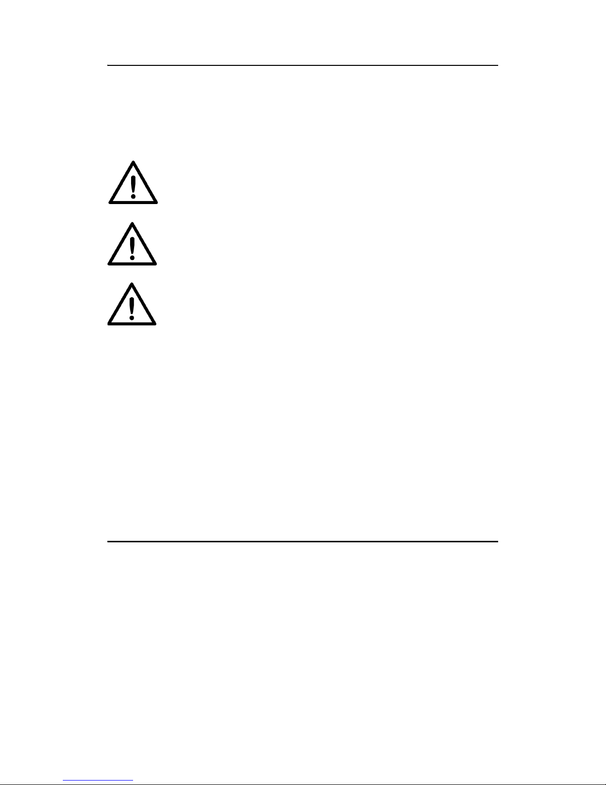
Attaching the H2 Cabled Handle
The HE40T uses the battery compartment to “snap to” the handle.
Figure 1–1 shows the H2 handle with flexible connector.
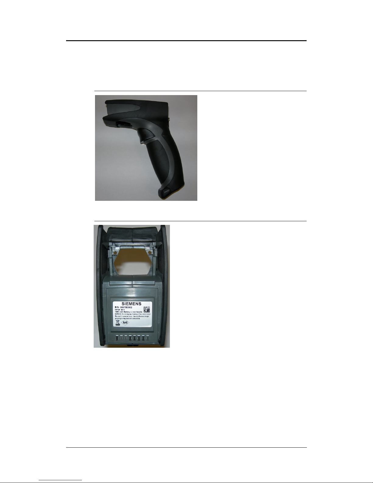
Figure 1–2 shows the battery blank.
FIGURE 1–1. H2 Handle with Flexible Connector
Flexible Connector
FIGURE 1–2. H2 Handle with Battery Blank
To attach the handle to the reader:
1. Push the 8-pin DIN connector at the end of the reader into the
flexible connector at the end of the handle, as shown in
Figure 1–3.
2 HE40T Quickstart Guide Rev 1.0.1, Dec. 2006
Page 13

FIGURE 1–3. Attaching the H2 Handle
Flexible
Connector
2. Insert the tab on the back of the handle into the reader
(Figure 1–3).
3. Snap the reader onto the handle, matching the battery
compartment to the battery connectors, visible inside the
handle, as shown in Figure 1–3.
The HE40T can be secured further with threaded screws on the
under side of the handle, and on the end of the flexible connector, as
shown in Figure 1–4.
FIGURE 1–4. Location of Threaded Screws
Rev 1.0.1, Dec. 2006 HE40T Quickstart Guide 3
Page 14
Attaching the BH1/BH2 Battery Handle
The HE40T uses the battery compartment to “snap to” the handle.
The BH1/BH2 handle is shown in Figure 1–5. The handle with
battery is shown in Figure 1–6.
FIGURE 1–5. BH1/BH2 Handle
FIGURE 1–6. BH1/BH2 Handle with Battery
To attach the handle to the reader:
1. Insert the tab on the back of the handle into the reader, as
shown in Figure 1–7.
2. Snap the reader onto the handle, matching the battery
compartment to the battery connectors, visible inside the
handle, as shown in Figure 1–7.
4 HE40T Quickstart Guide Rev 1.0.1, Dec. 2006
Page 15
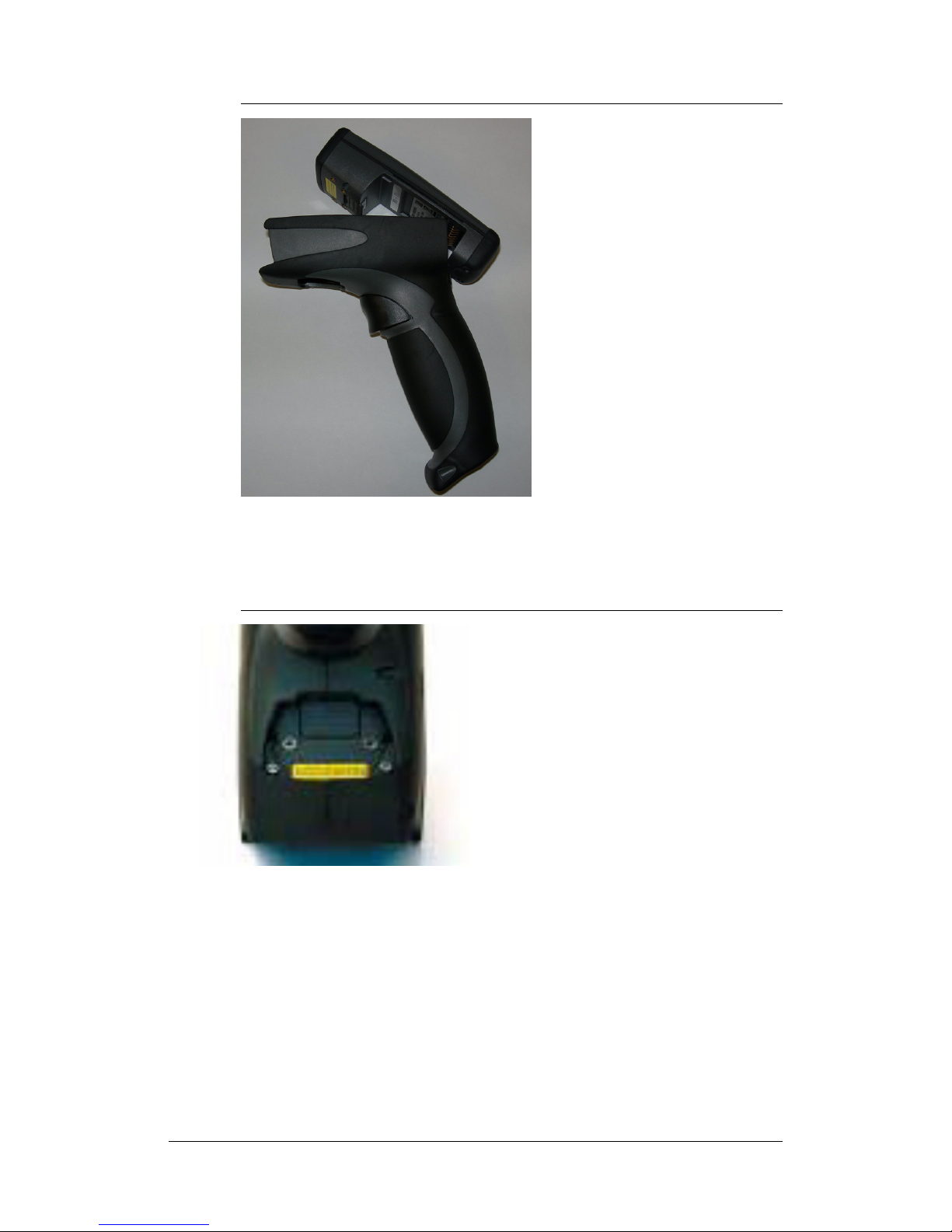
FIGURE 1–7. Attaching the BH1/BH2 Handle
The HE40T can be secured further with threaded screws on the
under side of the handle, as shown in Figure 1–8.
FIGURE 1–8. Location of Threaded Screws
Rev 1.0.1, Dec. 2006 HE40T Quickstart Guide 5
Page 16

HE40T Wireless
This HE40T features a Bluetooth® wireless radio. The radio allows
for point to point wireless communication with other Bluetooth
devices that support serial port protocol (SPP). The following
information will give you general instructions on connecting your
HE40T to a desktop or laptop computer with a Bluetooth radio.
Connecting With A QuickConnect Code
If you purchased a CodeXML Bluetooth Modem or a Belkin®
Bluetooth adapter from Siemens or from an authorized distributor, a
QuickConnect code was included, as shown in Figure 1–9.
FIGURE 1–9. Sample QuickConnect Code
Sample Code
The QuickConnect code has the information of the Bluetooth
address (often a reference to go to the BD_ADDR) of that device.
You can usually find the 12-character Bluetooth address
somewhere on the device near the device’s serial number
(Figure 1–10). This code will link your HE40T directly to the
desired Bluetooth device.
FIGURE 1–10. Locating the Bluetooth Address
HE40T Wireless Setup
Note: While installing the Bluetooth Configuration Manager
software that was included with your Bluetooth adapter, make sure
to note the Virtual COM Port number the software assigned for the
adapter (e.g., COM 10). This is the COM Port your HE40T will
connect through.
6 HE40T Quickstart Guide Rev 1.0.1, Dec. 2006
Page 17

To connect your reader:
1. Scan the Reset to RF Factory Defaults code shown in
Figure 1–11.
FIGURE 1–11. Reset to RF Factory Defaults Code
Reset to RF
Factory Defaults
QuickConnect (Sample)
Scan the QuickConnect code
that matches the Bluetooth
address of your device
2. Scan the QuickConnect code you received.
3. The HE40T will automatically connect. By default, the HE40T
will beep once after it connects and beep three times in a row if
it did not connect.
4. Scan the Save Settings code (Figure 1–12) to the right if you
want to save the wireless connection settings to the HE40T so
that the HE40T will automatically try to connect wirelessly the
next time it is powered on.
FIGURE 1–12. Save Settings Code
Save Settings
Radio Range and Transferring Data
The HE40T radio is a Class 1 device. If connected to another Class
1 device, the unit has roughly a 300 foot line of sight operating
range. If connecting to a Class 2 or Class 3 device, the operating
range may drop to match the lower range. Once a unit is connected,
the application software on the host must be open to receive data.
When the HE40T detects the radio is out of range, the HE40T will
store data on the reader’s non-volatile memory.
Rev 1.0.1, Dec. 2006 HE40T Quickstart Guide 7
Page 18

For more information about setting up and using the HE40T with a
wireless Bluetooth configuration, consult the HE40T User Manual.
HE40T Cables
The HE40T is available with USB, RS-232 and PS2 cables. All of
the cables are connected to the HE40T with a 8-pin DIN connector.
Different cables may be required for different hosts.
• HE40T with H2 Cabled Handle — The 8-pin DIN connection
is at the bottom of the handle. Firmly push the 8-pin connector
into the bottom of the handle. The cable has a locking
mechanism that will firmly hold the cable in place
(Figure 1–13). To detach the cable from the reader, you must
pinch the plastic on the 8-pin DIN (Figure 1–13) and pull back
to disengage the connector.
FIGURE 1–13. Handle with Cable Attached
Install the optional cable clip to further secure the cable to the
handle with two threaded screws, as shown in Figure 1–14.
FIGURE 1–14. Securing Cable Clip with Two Threaded Screws
8 HE40T Quickstart Guide Rev 1.0.1, Dec. 2006
Page 19
• HE40T with BH1/BH2 Battery Handle — Firmly push the
8-pin connector into the back end of the reader, as shown in
Figure 1–15. The cable has a locking mechanism that will
firmly hold the cable in place. To detach the cable from the
reader, you must pinch the plastic on the 8-pin DIN and pull
back to disengage the connector.
FIGURE 1–15. Handle with Cable Attached
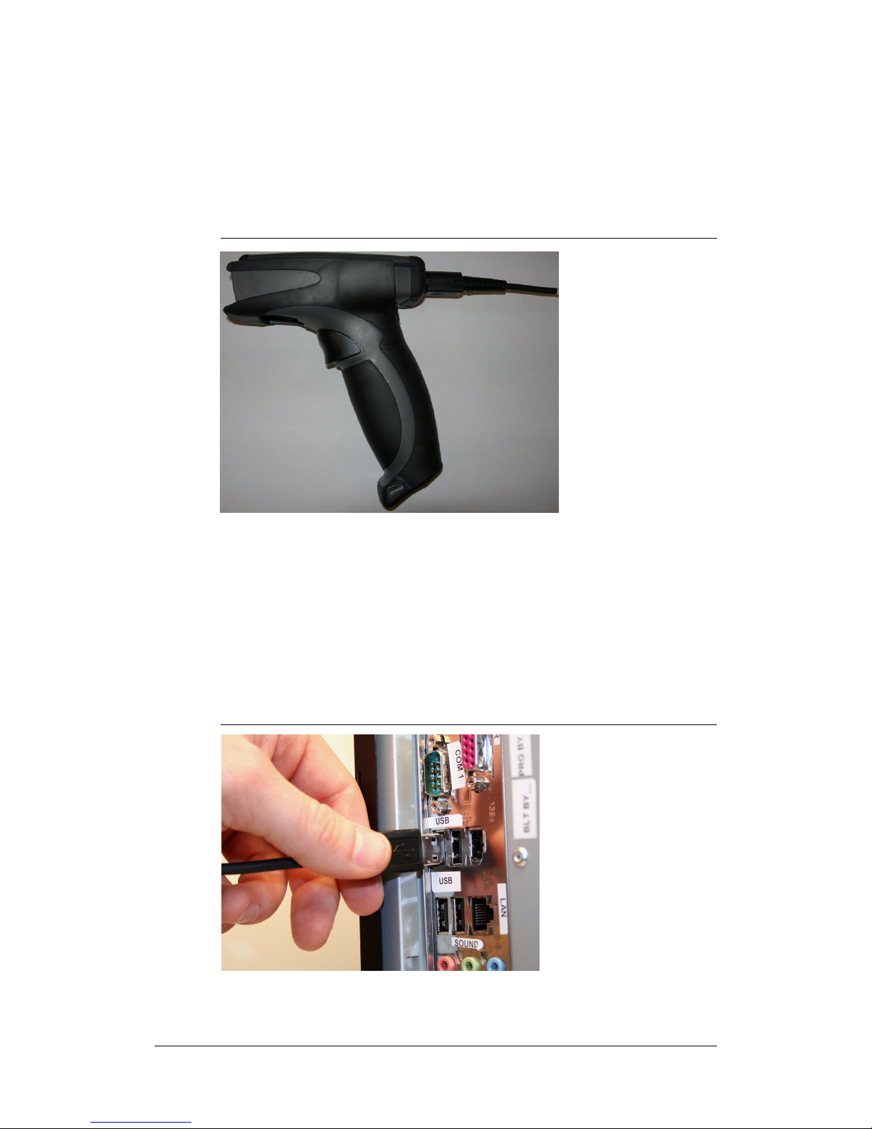
USB Cable Connection
1. Attach the USB cable to the HE40T.
2. Connect the USB cable to the host in any available USB host
port, as shown in Figure 1–16. You DO NOT need to power off
your host computer.
FIGURE 1–16. Connecting the USB Cable
3. Once properly connected to the host computer, the HE40T will
power on and beep. The reader is shipped pre-configured.
Rev 1.0.1, Dec. 2006 HE40T Quickstart Guide 9
Page 20
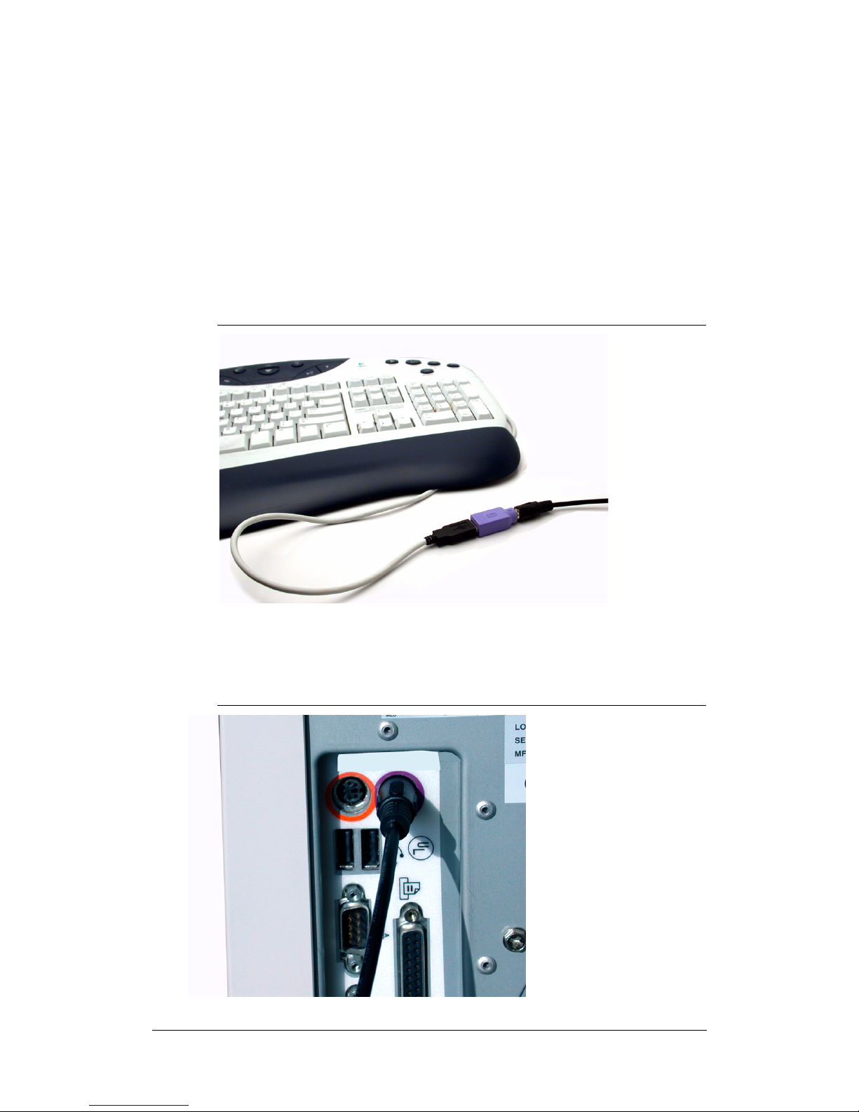
PS2 Cable Connection
1. Power off the host computer. This process requires shutting
down your computer. If you disconnect your computer
keyboard while it is running, your computer will lock up.
2. Attach the PS2 cable to the HE40T.
3. If you have a cabled keyboard, detach the keyboard cable from
your computer and connect that same connector to the female
connection on the HE40T PS2 cable, as shown in Figure 1–17.
FIGURE 1–17. Connecting the Keyboard Cable
4. Now, connect the male HE40T PS2 connector into the
keyboard port on your computer, as shown in Figure 1–18.
FIGURE 1–18. Connecting the PS2 Connector to Your Computer
10 HE40T Quickstart Guide Rev 1.0.1, Dec. 2006
Page 21
The HE40T is powered by the PS2 port and does not require a
power supply. Once properly connected, the HE40T will power on.
The reader is shipped pre-configured.
RS-232 Cable Connection
1. Attach the RS-232 cable to the HE40T.
2. Connect the RS-232 cable to your host computer.
3. The RS-232 interface has an optional power supply. If you
have a power supply, plug the power supply adapter into the
RS-232 cable and then plug the power adapter into a wall
socket. HE40T will power on once connected.
4. If battery power (no power adapter) is being used, press one of
the red buttons for one second to power on the reader. The
reader is shipped pre-configured.
USB Cable Settings
• USB Keyboard Mode — Data is sent from the reader and
interpreted by the host computer as if a US keyboard was being
used to enter data.
• USB Downloader — Communication method used to upgrade
firmware.
FIGURE 1–19. USB Codes
USB Keyboard
All other USB settings (including Virtual COM settings) may be
found in the HE40T User Manual. For further instructions
regarding upgrading firmware, please consult your Siemens
representative.
USB Downloader
Reset to USB
Factory Defaults
PS2 Cable Settings
PS2 Mode — Data is sent from the Reader and interpreted by the
host just as if a US keyboard was being used to enter data.
Rev 1.0.1, Dec. 2006 HE40T Quickstart Guide 11
Page 22
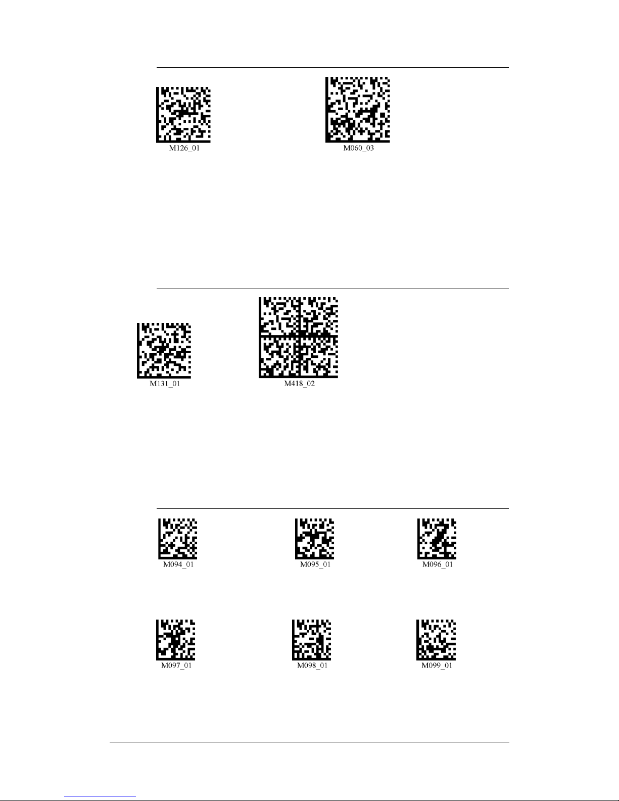
FIGURE 1–20. PS2 Codes
PS2 Mode
Reset to PS2
Factory Defaults
RS-232 Cable Settings
RS-232 One Way Mode — Data is sent from the Reader as serial
data through the RS-232 port.
FIGURE 1–21. RS-232 Codes
RS-232 Default Settings
Mode: RS-232 One Way
Mode Max Range
Baud Rate: 57600
Stop Bits: 1
Data Bits: 8
RS-232 One
Way Mode
Reset to RS-232
Factory Defaults
Parity: None
Baud Rates
Scan the codes in Figure 1–22 to set the baud rate:
FIGURE 1–22. Baud Rate Codes
4800
38400 57600
9600
19200
115200
Default
12 HE40T Quickstart Guide Rev 1.0.1, Dec. 2006
Page 23

Save Settings
Save changes made to the HE40T configuration by scanning the
codes in Figure 1–23:
FIGURE 1–23. Save Settings
Save Settings
Targeting and Reading Techniques
The HE40T utilizes digital camera technology to take a picture of a
symbol. Once an image is captured, the HE40T utilizes Siemens’
industry leading decoder to extract data from the captured image.
The H2 Cabled Handle and BH1/BH2 Battery Handle each feature
a trigger on the handle, as shown in Figure 1–24. The two triggers
on the top of the unit also work when the handle is attached.
FIGURE 1–24. Handle with Trigger
Caution
Laser in the HE40T
LASER RADIATION - AVOID LONG TERM
VIEWING OF DIRECT LASER RADIATION LASER CLASS 2A
Wavelength 630 nm - Maximum radiant power: < 1mW
EN 60825-1:2003
Rev 1.0.1, Dec. 2006 HE40T Quickstart Guide 13
Page 24

Reading Symbols with the HE40T
1. The HE40T features omnidirectional decoding. Center the
symbol in any orientation within the laser dot aiming pattern,
as shown in Figure 1–25.
Note: The HE40T can read a symbol that is not centered;
however, the HE40T performs best when a code is centered.
FIGURE 1–25. Centering Symbol Within the Laser Dot
2. The HE40T was developed to decode both very small 2-D
symbols and larger 1-D symbols. The unit features two imagers
to create an innovative dual decode zone. The HE40T features
a high speed processor and decodes both zones simultaneously
by default. The unit has one imager focused on a near-field for
smaller codes (optimal focal point is 4 inches) and one imager
focused on a far-field for larger codes (optimal focal point 9
inches). To read smaller symbols, move the HE40T closer to
the symbol. To read larger symbols, move the unit farther away
from the symbol. The entire HE40T decode zone varies
between two (2”) and twenty (20+”) or more inches.
3. Hold the HE40T Reader still - DO NOT SWIPE OR MOVE
THE READER. Press the trigger until the HE40T beeps,
indicating the bar code has been successfully decoded.
Programming Codes
A programming code symbol encodes special messages used to
program the HE40T.
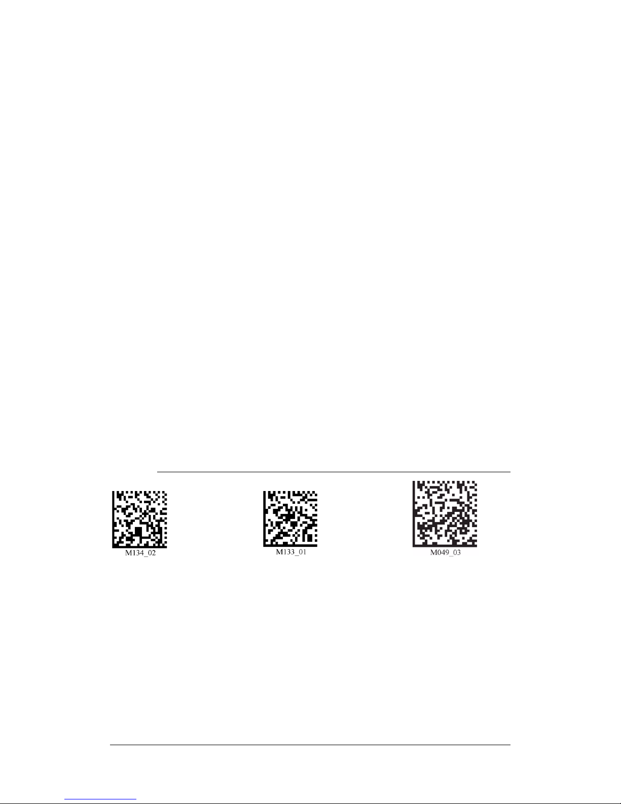
Symbology Settings
Symbology Defaults
Data Matrix ON Interleaved 2 of 5 OFF
Codabar OFF UPC OFF
Code 128 OFF QR/Micro QR OFF
Code 93 OFF PDF417 OFF
Code 39 OFF
14 HE40T Quickstart Guide Rev 1.0.1, Dec. 2006
Page 25

FIGURE 1–26. Symbology Programming Codes
Codabar On Codabar Off
Code 128 On
Code 128 Off Code 93 On Code 93 Off
Code 39 On Code 39 Off
I 2 of 5 Off
UPC On
I 2 of 5 On
UPC Off
UPC Extension On UPC Extension Off
QR/Micro QR On
PDF417 On
Rev 1.0.1, Dec. 2006 HE40T Quickstart Guide 15
QR/Micro QR Off
PDF417 Off
Save Settings
Page 26

FIGURE 1–27. Symbology Programming Codes (Continued)
All 1D On
All 1D Off
Save Settings
DoD UID Settings
The HE40T unit complies with MIL-STD-130, ISO 15434, and
ISO 15418 to construct a Unique Items Identifier (UII).
The following UID data output options are applicable to Data
Matrix only and have no effect on other symbologies:
• UII DM On — The HE40T is configured to construct UII. If
there is a valid UII, a UII string is outputted. For decoded Data
Matrix with invalid UII, HE40T stops image acquisition
without an output string.
• UII/ISO 15434 DM On — The HE40T is configured to
construct UII or any ISO 15434 compliance data. The output is
either UII or valid ISO 15434 syntax complied data. For a
decoded Data Matrix with invalid UII or ISO 15434 syntax, the
HE40T stops image acquisition without an output string.
• UII DM with Data Field — The HE40T is configured to
construct UII and output additional data fields.
• UII/ISO 15434 DM with Data Field — The HE40T is
configured to construct UII or any ISO 15434 compliance data
and output additional data fields.
The following options apply to all symbologies:
• UII On for All Symbologies — The HE40T is configured to
construct UII only for all symbologies. For decoded
symbologies with invalid UII, the HE40T stops image
acquisition without an output string.
• UII Off — The HE40T is back to normal decoder behavior
without constructing UII.
16 HE40T Quickstart Guide Rev 1.0.1, Dec. 2006
Page 27

FIGURE 1–28. UII Codes
UII DM On
UII/ISO 15434 DM On
UII/ISO 15434 DM with Data Field
UII On for all Symbologies
Save Settings
UII Off
UII DM with Data Field
Batch Mode
The HE40T unit features a batch mode for applications requiring a
portable reader. Batch mode allows a user to store scanned data to
the reader’s non-volatile memory. You may transfer the data to a
host computer when needed. To utilize batch functionality, you will
need to use the BH1/BH2 battery handle.
The HE40T dedicated batch memory is a minimum of 1MB. To
determine the number of reads that may be stored, divide the
average bytes of a scan into the total minimum memory.
Auto Transfer Buffer Memory
By default, when reconnected, the HE40T will automatically
transfer any data in memory once a connection to a host is
established. If your application is not ready, the reader will send the
data anyway and the data could be lost. If you do not wish for the
reader to immediately send data upon connection, please scan the
Disable Auto Transfer Buffer Memory.
Rev 1.0.1, Dec. 2006 HE40T Quickstart Guide 17
Page 28

FIGURE 1–29. Auto Transfer Buffer Memory Codes
Send & Buffer Mode
Log Only Mode
Save
Settings
(Default)
Send & Log Mode
Transfer All Data Memory
Transfer Only Unsent Data Delete Scanned Data From Memory
Enable Auto Transfer
Buffer Memory (Default)
Disable Auto Transfer
Buffer Memory
18 HE40T Quickstart Guide Rev 1.0.1, Dec. 2006
Page 29
Trigger Programming
Left Trigger
FIGURE 1–30. Left Trigger Programming Codes
Read With Both Imagers (Default)
Read With Far-Field Imager
Read With Near-Field Imager
Right Trigger
FIGURE 1–31. Right Trigger Programming Codes
Read With Both Imagers (Default)
Read With Far-Field Imager
Rev 1.0.1, Dec. 2006 HE40T Quickstart Guide 19
Read With Near-Field Imager
Page 30

Handle Trigger
FIGURE 1–32. Handle Trigger Programming Codes
Read With Both Imagers (Default)
Read With Far-Field Imager
Read With Near-Field Imager
Image Resolution Mode
• SXGA Only — Cell size or X dimension of most bar codes no
greater than 15 mils (0.015 inches).
• VGA Only — Cell size greater than 15 mils.
FIGURE 1–33. Image Resolution Mode Codes
SXGA & VGA
SXGA Only
VGA Only (Default)
Turbo Dot Peen Mode
The HE40T with the default settings offers the best overall
performance for Data Matrix DPM reading. For reading dot peen
marks with cell size larger than 15 mils or 0.015 inches, it is often
possible to improve the reading performance by enabling the Turbo
Dot Peen mode. It is also recommended that Read With Near Field
Only mode and VGA Only mode be used in conjunction with the
Turbo Dot Peen On mode to achieve the best reading response.
20 HE40T Quickstart Guide Rev 1.0.1, Dec. 2006
Page 31
Note: Turbo Dot Peen mode should not be used for reading small
marks (dot peen or others) as it may increase the processing time
and reduce the robustness of reading small marks.
FIGURE 1–34. Turbo Dot Peen Mode Codes
On
Off
Miscellaneous Programming Codes
Prefix Settings
If you scan the following codes, you may lose your current settings.
Save settings on your reader before scanning the prefix codes. If
you scan more than one prefix, you will receive each scanned prefix
in your scanned data (i.e., if you scan comma prefix twice, you will
get two comma prefixes). Scan the codes in Figure 1–35 and
Figure 1–36 to set the appropriate prefix:
FIGURE 1–35. Prefix Settings
Save Settings
Prefix - Comma Prefix - Space
Prefix - Carriage Return
Line Feed (RS-232)
Rev 1.0.1, Dec. 2006 HE40T Quickstart Guide 21
Prefix - Tab
(RS-232)
Page 32

FIGURE 1–36. Prefix Settings (Continued)
Prefix - Tab
(USB/PS2)
Prefix - Erase
This code will erase
all prefix data
Save Settings
Suffix Settings
If you scan the codes in Figure 1–37 and Figure 1–38, you may lose
your current settings. Save settings on your reader before scanning
the Suffix codes. If you scan more than one suffix, you will receive
each scanned suffix in your scanned data (i.e., if you scan comma
suffix twice, you will get two comma suffixes). Scan the codes in
Figure 1–37 and Figure 1–38 to set the appropriate suffix:
FIGURE 1–37. Suffix Settings
Suffix - Space
Suffix - Enter
(USB/PS2)
22 HE40T Quickstart Guide Rev 1.0.1, Dec. 2006
Suffix - Comma
Suffix - Carriage Return
Line Feed (RS-232)
Page 33

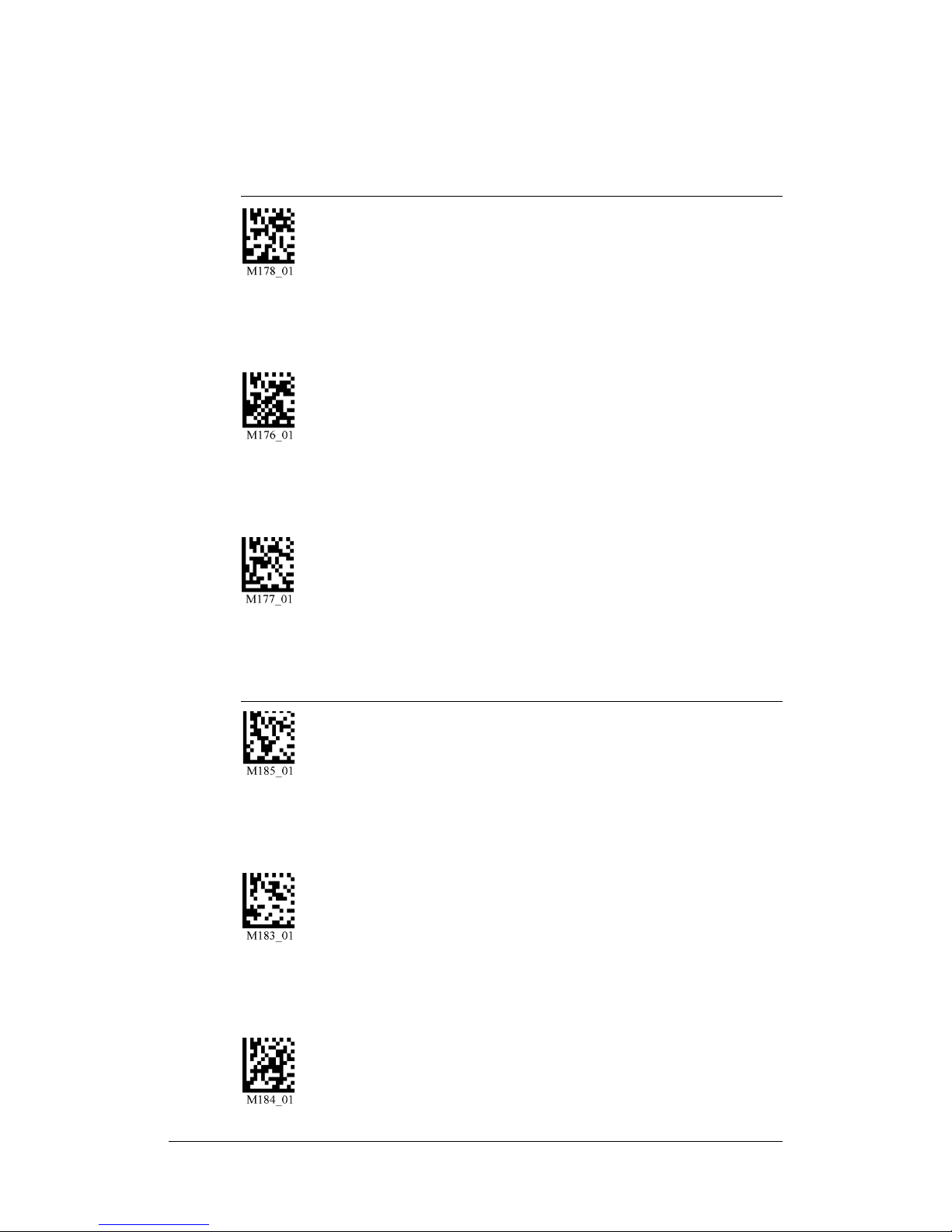
FIGURE 1–38. Suffix Settings (Continued)
Suffix - Carriage Return
(RS-232)
Suffix - Tab
(RS-232)
Suffix - Line Feed
(RS-232)
Suffix - Tab
(USB/PS2)
Suffix - Erase/None
Save Settings
This code will eras
all suffix data
Rev 1.0.1, Dec. 2006 HE40T Quickstart Guide 23
Page 34

Volume and Vibration Settings
Scan the codes in Figure 1–39 to set volume and vibrations settings:
FIGURE 1–39. Volume & Vibration Settings Codes
Vibrate On
Beep On
Reader ID & Firmware Version
Minimum Requirements
Operating Systems: Windows© 2000, XP
Interfaces: USB, RS-232, and PS2
Bluetooth™: HE40T only supports Bluetooth serial profile
Vibrate On
Beep Off
Vibrate Off
Beep On
Save Settings
24 HE40T Quickstart Guide Rev 1.0.1, Dec. 2006
 Loading...