

Page 1
Installation Instruct ions
Model HCP
Intelligent Control Point
INTRODUCTION The Model HCP Intelligent Control Point from Siemens
Industry, Inc. provides remote, independent control of
any of the following:
1. A notification appliance circuit (NAC)
2. A telephone zone (XLS only)
3. A speaker zone (25V or 70.7V RMS) (XLS only,
FV2025/2050, FV922/924)
The HCP communicates through the DLC device loop
card of the FireFinder-XLS System, the FS-DLC device
loop card of the FS-250 System, the FC922/FV922,
FC2025/FV2025 periphery FCI2016 Board (250p)
detector circuits, and the FC2050/FV2050, FC924/FV924
FCI2017 periphery board (500p) detector circuits. Each HCP
uses one device address on the device loop.
PROGRAMMING
POINTS
E
ID
S
K
C
A
B
N
6
O
1
B
5
T
4
3
2
1
SIEMENS
MODEL: HCP
DEVICEADDRESS:
U
A
C
W
CT
NE
N
O
B
C
1
IS
B
D
T
N
O
INSTALLATIONINSTRUCTIONS
P/N315-034860
SIEMENSINDUSTRY, INC.
FLORHAMPARK, NJ, 07932
T
6
N
"2"
&
IO
"1"
T
INAL
RM
G
IN
M
AT TE
M
A
R
IRE
G
O
R
P
E
R
O
F
E
E
ID
S
K
C
A
B
N
O
1
2
B
2
3
4
5
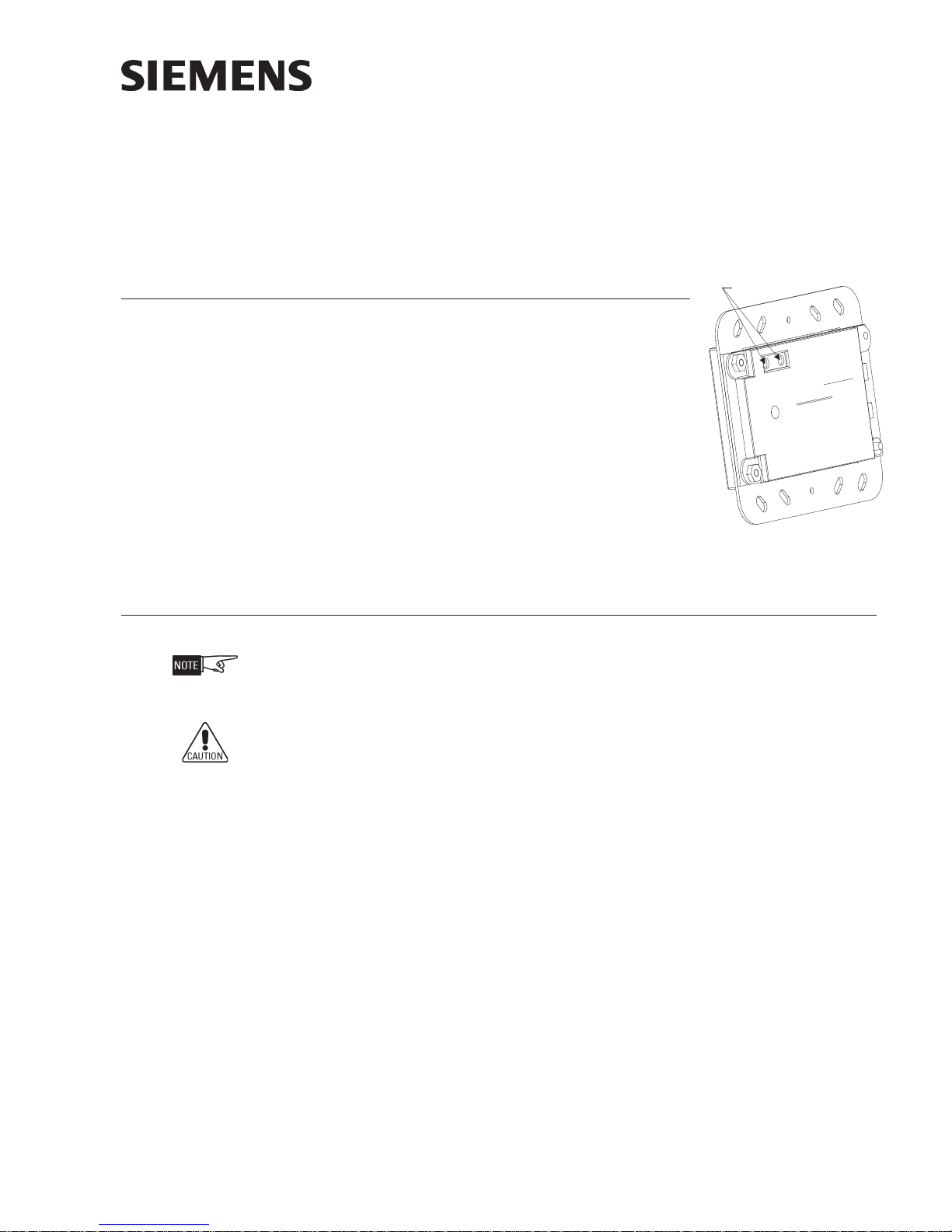
Figure 1
HCP Intelligent Control Point
PROGRAMMING Use the DPU Programmer/Tester to program and test the module.
The HCP may only be assigned addresses 1 to 60. It is recommended to program
the HCP devices first to ensure that enough addresses have been reserved for them.
Other devices may then be assigned to addresses in this range that were not
assigned to an HCP.
Disconnect wire at terminal 1 and 2 on TB1 before programming.
To set the HCP device address:
• Plug the programming cable of the DPU Programmer/Tester into the twopin programming points on the HCP. (See Figure 1 for location.)
• Set the device address for the HCP by following the instructions in the DPU
Programmer/Tester Manual, P/N 315-033260.
Each HCP can be assigned a custom message using either the Zeus Programming Tool
(XLS System), the FS-CT2 (FS-250 System), the FC2025/2050, FV2025/2050 FSX2002
Engineering Tool, or the FC922/924, FV922/924 FSX7212 Engineering Tool. Refer to
the Zeus Quick Start Manual, P/N 315-033875, or the FS-250 Programming Manual, P/
N 315-049403, as applicable.
P/N 315-034860-13
Building Building
Building
Building Building
SiemensSiemens
Siemens
SiemensSiemens
TT
ecec
hnologies Dihnologies Di
T
ec
hnologies Di
TT
ecec
hnologies Dihnologies Di
Industry Industry
Industry
Industry Industry
visionvision
vision
visionvision
,,
Inc. Inc.
,
Inc.
,,
Inc. Inc.
Page 2

COMPATIBILITY The following minimum revisions are required for proper operation of the HCP:
:METSYSSLX:METSYS052-SFMETSYS02SF
CLD0000.00.40CLD-SF05.1
IMP0000.00.40CAN81.20502/5202CFxx.xx.14
21-CSP0000.00.70
04-CAZ
SUEZ9100.00.40
0000.80.20
*0000.80.031
LENAP0.50502/5202VFxx.xx.06
OGISED
ORPSUREBREC
429/229CFxx.xx.14
429/229VFxx.xx.06
90.20.veR04-CAZ*
.0000.01.031/0000.01.20.veRro0000.80.031/0000.80.20.veRottreveR.PCHeht
WIRING
Remove all system power before installation, first battery then AC. (To power up,
connect the AC first, then the battery.)
Power down the 24 VDC power supply and the input source (ZAC, etc.) before
installing the HCP.
All wiring must comply with national and local codes. All wire must be 18 AWG
minimum, 12 AWG maximum.
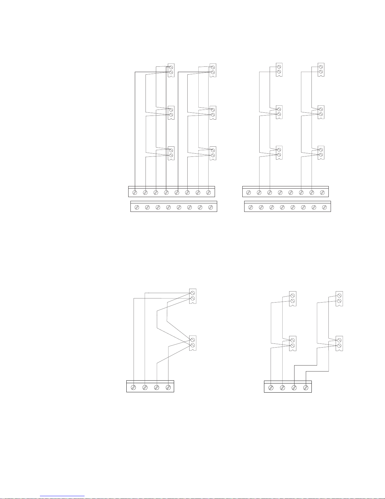
Device Loops The HCP communicates with the FireFinder-XLS/FS-250/Desigo FC2025/2050,
FV2025/2050/Cerberus PRO FC922/924, FV922/924 Systems through its addressable
device loops. These loops are connected to the DLC via terminal blocks on the CC-5
or CC-2 cardcage (XLS) or to the FS-DLC via TB3 on the FS-MB/FS-MB2 main board
(FS-250). They may be wired Class A (Style 6) or Class B (Style 4). Figure 2 shows
both wiring types and the connections to the DLC. See the DLC Installation Instructions, P/N 315-033090, for more information. Figure 3 shows both wiring types and
connections to the FS-DLC. See the FS-250 Installation, Operation and Maintenance
Manual, P/N 315-049353, for more information. Figure 4 shows both wiring types and
connections to the Periphery boards. See the Desigo FC2025/2050 FV2025/2050
Configuration Manual, Document ID A6V10315023, for more information. Figure 5
shows both wiring types and connections to the Periphery boards. See the Cerberus
PRO FC922/924 FV922/924 Configuration Manual, Document ID A6V10333423, for
more information.
htiwelbitapmocTONera0000.42.20.veRdna0000.12.20.veR,0000.90.031/0000.
HCP Power Supply For FireFinder-XLS Systems, compatible power supplies for the HCP are the PSC-12,
PSX-12, and PAD-4. Wiring should be connected to TB3 on the PSC-12 and PSX-12, or
the auxiliary power supply on the PAD-4.
For FS-250 Systems, the HCP is powered by the NAC circuits and PAD-4. Wiring
should be connected to the NAC circuits on the main board or the auxiliary power
supply on the PAD-4.
Siemens Industry, Inc.
Building Technologies Division
P/N 315-034860-132
Page 3
HCP
TB1
1
2
HCP
TB1
1
2
HCP
TB1
1
2
12345678
910111213141516
CLASS A WIRING*
NO T-TAPPING ALLOWED
BOTH ZONES MUST BE WIRED AS CLASS A
12345678
910111213141516
CLASS B WIRING**
T-TAPPING ALLOWED
BOTH ZONES MUST BE WIRED AS CLASS B
*OPERATES IN FULL CONFORMANCE WITH STYLE 6 (ULC DCLA)
ZONE 1
DLC LOCATED IN
ONE SLOT OF CC-5 / CC-2
LINE 1
LINE 1
LINE 1 (RETURN)
LINE 1 (RETURN)
LINE 1 (OUT)
LINE 1 (OUT)
ZONE 2
LINE 2
LINE 2
LINE 2 (OUT)
LINE 2 (OUT)
LINE 2 (RETURN)
LINE 2 (RETURN)
NOT USED
NOT USED
NOT USED
NOT USED
**OPERATES IN FULL CONFORMANCE WITH STYLE 4 (ULC DCLB)
HCP
TB1
1
2
HCP
TB1
1
2
HCP
TB1
1
2
HCP
TB1
1
2
HCP
TB1
1
2
HCP
TB1
1
2
HCP
TB1
1
2
HCP
TB1
1
2
HCP
TB1
1
2
ZONE 1
ZONE 2
DLC LOCATED IN
ONE SLOT OF CC-5 / CC-2
CLASS
G
2
2
,
NOTES
1. Loop resistance 50 ohms
Max with 252 devices on
the loop. Refer to the DLC
Installation Instructions,
P/N 315-033090 if the
number of devices is less
than 252.
2. 12-18 AWG wire.
3. No EOL device required.
4. Supervised, power limited
per NEC 760.
5. All wiring must conform
to national and local
electrical codes.
Figure 2
FireFinder-XLS Device Loop
Connections
NOTES
1. Loop resistance 180 ohms
max with 252 devices on
loop.
2. 12-18 AWG wire.
3. No EOL device required.
4. Supervised, power limited
per NEC 760.
5. All wiring must conform
to national and local
electrical codes.
A WIRIN
TB1
X1401/X1402
X1801/X1802
4 3 2 1
1+ 1- 2+ 2-
HCP
TB1
HCP
CLASS B WIRING
1
2
TB1
1
2
HCP
1
2
TB1
1
2
HCP
X1401/X1402
X1801/X1802
4 3 2 1
1+ 1- 2+ 2-
TB1
1
HCP
TB1
1
HCP
Figure 3
FS20 Device Loop
Connections
Siemens Industry, Inc.
Building Technologies Division
Detector circui ts on periphery board
for FC922/FV922
FC2025/FV2025
P/N 315-034860-133
Page 4
NOTES
1. Loop resistance 50 ohms
Max with 252 devices on
the loop. Refer to the FS250 Manual, P/N 315049353 if the number of
devices is less than 252.
2. 12-18 AWG wire.
3. No EOL device required.
4. Supervised, power limited
per NEC 760.
5. All wiring must conform
to national and local
electrical codes.
Figure 4
FS-250 Device
Loop Connections
FS-DLC Device
Loop Circuit
FS-DLC Device
Loop Circuit
CLASS A* INSTALLATION
*OPERATES IN FULL CONFORMANCE WITH STYLE 6
LINE 1 (OUT)
LINE 1 (RETURN)
LINE 2 (RETURN)
LINE 2 (OUT)
HCP
**OPERATES IN FULL CONFORMANCE WITH STYLE 4
LINE 1
NOT USED
NOT USED
LINE 2
HCP
NO T-TAPPING ALLOWED
TB1
2
1
CLASS B** INSTALLATION
TB1
2
1
HCP
T-TAPPING ALLOWED
HCP
(ULC DCLA)
ZONE
1
TB1
2
1
TB1
2
1
HCP
(ULC DCLB)
HCP
TB1
2
1
ZONE
1
TB1
2
1
DPU Loop Test When performing a loop test with the DPU be sure to apply power to the HCP.
Without power applied to the HCP a blinking “C” will appear on the DPU, indicating
that the HCP is in trouble.
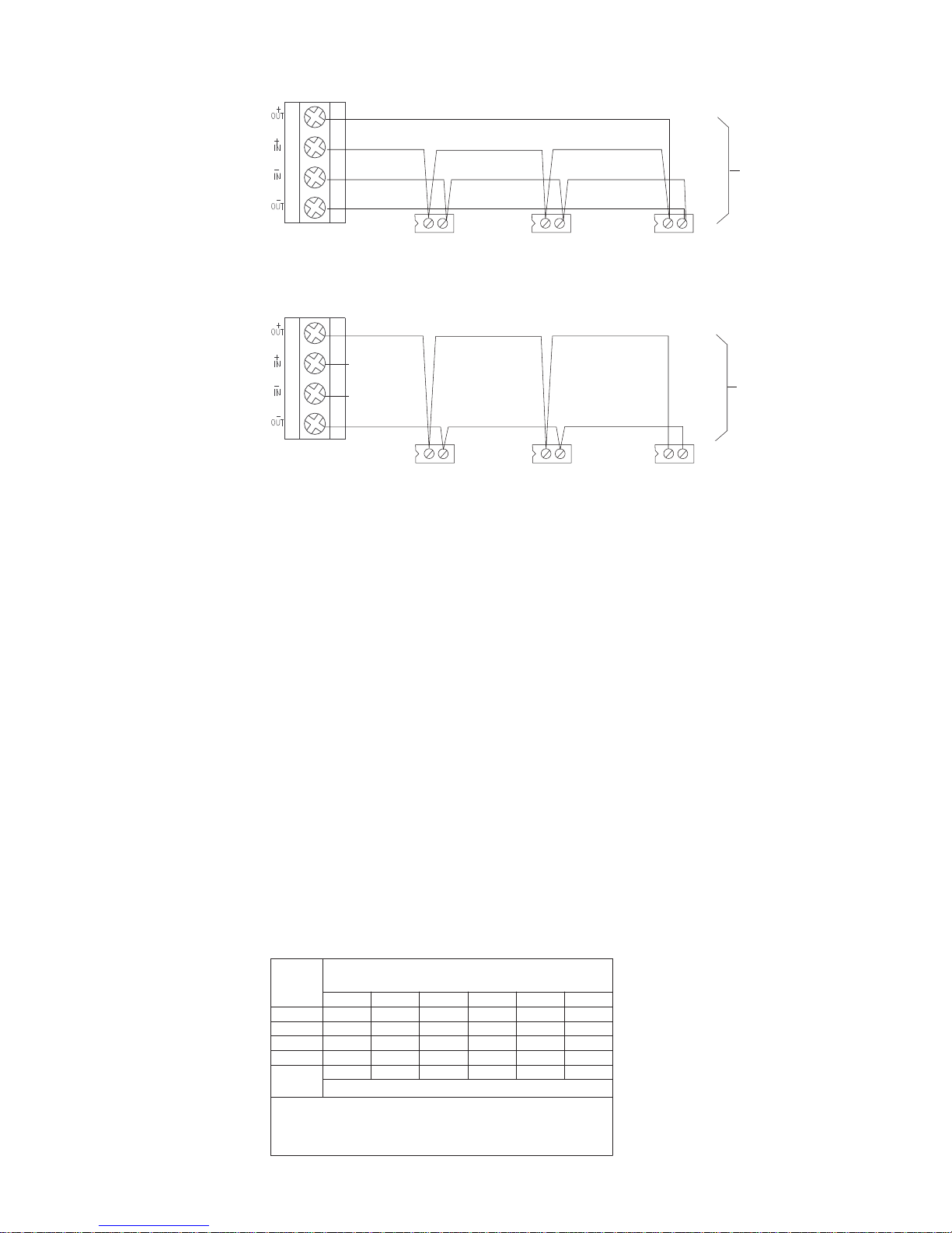
HCP As NAC Module This application uses the principle of polarity reversal to activate notification appli-
ances. Wiring is shown in Figure 4. Connect the HCP output zone wiring to the (+)
and (-) terminals of each notification appliance as shown in Figure 4. For a list of
compatible devices, refer to P/N 315-096363.
When used as a NAC module, the 24VDC provides power for the supervision circuitry
and to the notification appliances when they are activated. The power source must be
power limited. See the HCP Power Supply section (above) for compatible power sources.
The maximum output load that may be connected to an HCP is 1.5A at 24 VDC. If the 24
VDC is lost or the NAC line is broken or shorted while the HCP is in supervisory mode, a
trouble condition displays at the FireFinder-XLS, FS-250 System control panel, the Desigo
FC2025/2050, FV2025/2050 Operating Unit, and the Cerberus PRO FC922/924, FV922/
924 Operating Unit. For FS-250 Systems, the NAC circuit must be set to “always on” in
the panel or FS-CT2 configuration tool. See the Line Resistance table below for the
allowable line resistance for each HCP output circuit.
ECNATSISERENILTIUCRICTUPTUOPCHELBAWOLLAMUMIXAM
MUMIXAM
CD
RESIR
TNERRUC
)spmAni(
437.233.276.100.133.—
308.205.200.205.
268.276.233.200.276.100.1
139.238.276.205.233.200.2
5.69.229.238.257.276.205.2
SETON
:
mhO1.0mhO52.0mhO5.0mhO57.0mhO1smhO5.1
100.1—
rruclatotehtfI.2
.seriwhtobroferadeificepssecnatsiseR.1
ECNATSISERENILDNATNERRUCRESIRCDDEIFICEPSROF
)smhOni(ECNATSISERRESIRCD
RESIRNOPCHHCAEROFECNATSISERPOOLMUMIXAM
eratahtseilppusCDV42yrailixualacol,A4sdeecxetnemeriuqertne
.desuebyam,4-DAPsnemeiSsahcus,esugnilangisnoitcetorperifrofdetsilLU
Siemens Industry, Inc.
Building Technologies Division
P/N 315-034860-134
Page 5

.
A
LL WIRING MUST COMPLY WITH NATIONAL AND LOCAL CODES.
D
DLC/FS-DLC
DEVICE LOOP
DC INPUT RATED
18.8-28.2VDC
SUPV: 30m A
ACTIVATE D: 1.5A MAX
C INPUT: 18.8-28.2VDC FILTERED FULL WAVE
XLS/FS-250: PAD-4* (TB16), FC2025/2050,
FCI2016/2017-U1 PERIPHERY BOARD AUX
POWER OR UL LISTED REGULATED 24 VDC
MODULE INPUT SUPPLY:
XLS: PSC-12 (TB3) or PSX-12 (TB3).
FS-250: FS-250 NAC Circuit.
FV2025/2050, FC922/924, FV922/924,
POWER SUPPLY (POWER LIMITED).
*REFER TO PAD-4 INSTALLATION INSTRUCTIONS, P/N 315-050217, FOR PROPER SETTING OF SWITCH 4. THE AUXILIARY POWER OUTPUT MUST BE CONFIGURED TO “ALWAYS ON”
LINE 2
PROGRAMMING
POINTS
EARTH
LINE 1
FROM
SUPERVISED STROBE ACTIVATION “SPECIAL APPLICATION”
18.8V-28.2V FILTERED FULL WAVE RECTIFIED
1 2 3 4 5 6
HCP HCP
6 5 4 3 2 1
SHIELD
HCP MODULE IS USED FOR
NAC SUPERVISION AND ACTIVATION
STYLE Y
SUPV: 1mA
ACTIVATED: 1.5A MAX
POLARITY SH OWN IN ACTIVE STATE
24K, W½, 5%
EOL RESISTOR
P/N 140-034677
24 VDC
NAC UNITS
SEE P/N 315-096363
PROGRAMMING
POINTS
EARTH
SHIELD
NAC SUPERVISION AND ACTIVATION
STYLE Z
24K, W, 5% ½
EOL RESISTOR
P/N 140-034677
1 2 3 4 5 6
6 5 4 3 2 1
HCP MODULE IS USED FOR
POSITIVE AND NEGATIVE
GROUND FA ULT
DETECTED AT
<500 OHMS FOR
TERMINALS 3-6 ON TB1.
The input power and NAC power inputs on TB2 (1-4)
must be connected to the same source.
Figure 5
HCP Used As An NAC Module
All HCPs connected to a given DLC/FS-DLC circuit
must reside within a single notification zone.
HCP As Telephone Zone When the HCP is used as a telephone zone module (FireFinder-XLS System only) as
shown in Figure 5, the 24 VDC provides power to the supervision and call-in detection
circuitry. If the 24 VDC is lost, a trouble condition displays on the PMI/PMI-2 of the
FireFinder-XLS.
The HCP provides a dial tone when a Fireman’s Master telephone (FMT) is taken off
hook or when a Portable FireFighter’s telephone (PFT) is jacked in.
Each HCP can support a maximum of 5 phones off hook. Throughout the system, no
more than 10 phones may be off hook at any one time.
The supervised telephone common talk riser starts at the TZC-8B module in the CAB
backbox. The common talk riser connects continuously to each HCP with a 10K end
of line device at the last HCP. Tie the shield of these riser wires together using
terminal 5 of TB2 and isolate them from the system circuits and the earth ground.
Individual phones may not be connected to a riser that is wired to HCPs. The TZC-8B
zone must be configured for Riser usage in Zeus.
Connect the supervised telephone zone wiring to the HCP with twisted pair cable.
Terminate at the last station with a 75K ohm end of line resistor. As with the common talk line described in the paragraph above, be sure that the shield is continuous
and isolated from both system circuits and earth ground and that the shields are
connected together using terminal 5 of TB-2.
Siemens Industry, Inc.
Building Technologies Division
P/N 315-034860-135
Page 6

FROM DLC DEVICE
LOOP IN CC-5 / CC-2
POWER LIMITED
LINE 1
LINE 2
SUPERVISED, 24 OHMS MAX
UNSHIELDED, USE TWISTED PAIR
POSITIVE AND NEGATIVE GROUND FAULT
DETECTED AT <500 OHMS FOR
TERMINALS 3-6 ON TB1.
USE TWISTED PAIR
SUPERVISED
24 OHMS MAX
UNSHIELDED
POINTS
EARTH
SHIELD
1 2 3 4 5 6
SHIELD
TO
6 5 4 3 2 1
10K, 1/2W, +/-5%
EOL RESISTOR
+
WARDEN’S STATIONS
(FTS SERIES)
75K, ¼W, +/-5%
EOL RESISTOR
P/N 140-050797
AT LAST STATION
NOTES:
1. THE SHIELD ON THE COMMON TALK
LINE MUST BE CONTINUOUS AND
CONNECTED ONLY TO EARTH
GROUND AT CONTROL PANEL.
2. ALL WIRING MUST COMPLY WITH
NATIONAL AND LOCAL CODES.
3. 12-18 AWG OR AS REQUIRED
BY THE LOCAL AUTHORITY
HAVING JURISDICTION.
1 2 3 4 5 6
+
PROGRAMMING
POINTS
HCP HCP
SHIELD
TO
6 5 4 3 2 1
HCP DC SUPPLY
FROM PSC-12 (TB-3),
PSX-12 (TB-3),
OR PAD-4* (TB16)
ELECTRICAL:
INPUT DC SUPPLY: 18.8 - 28.2VDC,
30mA MAX
FILTERED FULL WAVE
*REFER TO PAD-4 INSTALLATION INSTRUCTIONS, P/N 315-050217, FOR PROPER SETTING OF SWITCH 4. THE AUXILIARY POWER OUTPUT MUST BE CONFIGURED TO “ALW AYS ON”.
EARTH
SHIELD
FROM PREVIOUS HCP OR TZC-8B
(100 OHMS MAXIMUM
LINE RESISTANCE)
COMMON TALK RISER
(POWER LIMITED)
SEE TZC-8B INSTALLA TI ON
INSTRUCTIONS, P/N 315-034110,
FOR RISER RATINGS
SHIELD
WHITE
WHITE
WHITE
WHITE
*
REMOVE 10K TERMINATING RESISTORS FROM THE FJ-303sALL
FJ-303
FJ-303
BLACK
BLACK
BLACK
BLACK
75K, ¼W, +/-5%
EOL RESISTOR
P/N 140-050797
AT LAST FJ-303
PROGRAMMING
Figure 6
HCP Used As A Telephone Zone
HCP As (70.7V/25V) Speaker Zone in an XLSV System
When the HCP is used as a speaker zone (FireFinder-XLS System only), the 24 VDC
provides power to the supervision circuitry. If the 24 volts is lost or there is an open
or shorted speaker output line, a trouble condition displays on the PMI/PMI-2 of the
FireFinder-XLS.
The 70.7V/25V RMS audio input to the HCP must be power limited, such as from the
ZAC-40. The ZAC-40 supervises the audio connection path to the HCP and provides
up to 40 watts of power. The ZAC-40 can be wired Style Y (Class B) only. Refer to the
ZAC-40 Installation Instructions, P/N 315-035400 for further information. In order to
function properly during degrade mode, the DLC to which the HCP is connected
must be located in the same enclosure as the DAC-NET and ZAC-40 that supply
audio to the HCP.
When the HCP is used as a speaker zone, the output speaker lines are only supervised when the zone is not active. The audio output must not be allowed to exceed
25 watts. The approximate decibel loss for the total speaker zone wire length for
various wire gauge sizes is shown in Figure 7 for the 70.7V option and in Figure 8 for
the 25V option. Connect the speaker output as Style Y (Class B) as shown in Figure 9.
Siemens Industry, Inc.
Building Technologies Division
P/N 315-034860-136
Page 7

HCP As (70.7V/25V) Speaker Zone in a FV2025/FV2050 or FV922/FV924 System
100
0
-.5
-1.0
-1.5
-2.0
-2.5
200
300 400 500 600
TOTAL SPEAKER ZONE WIRE LENGTH (FEET)
dB LOSS
700 800 900 1000
SPEAKER LOAD: 25 WATTSAT 25V RMS
LOCATEDAT END OF RUN
DOES NOT INCLUDE ANY LOSS
IN RISER RUN
APPROXIMATE SPEAKER ZONE WIRE LOSS
IN DECIBELS FOR VARIOUS GAUGE WIRES VERSUS
TOTALSPEAKER ZONE WIRE LENGTH (FEET),
WHICH IS TWICE THE WIRE RUN LENGTH.
18 AWG
16 AWG
14 AWG
HCP USED FOR 25V RMS OPTION
The 70.7V/25V RMS audio input to the HCP must be power limited, such as from the
VCI2001-U1 Amplifier Card. The VCI2001-U1 supervises the audio connection path to
the HCP and provides up to 50 watts of power. The VCI2001-U1 can be wired Style Y
(Class B) or Style Z (Class A). Refer to the VCI2001-U1 Installation Instructions,
Document ID A6V10370410, for further information. In order to function properly
during degrade mode, the periphery FCI2016/2017-U1 to which the HCP is connected
must be located in the same enclosure as the FDNET and VCI2001-U1 that supply
audio to the HCP.
When the HCP is used as a speaker zone, the output speaker lines are only supervised when the zone is not active. The audio output must not be allowed to exceed
25 watts. The approximate decibel loss for the total speaker zone wire length for
various wire gauge sizes is shown in Figure 7 for the 70.7V option and in Figure 8 for
the 25V option. Connect the speaker output as Style Z (Class A) or Style Y (Class B) as
shown in Figures 10 and 11.
HCP USED FOR 70.7V RMS OPTION
SPEAKER LOAD: 25 WATTSAT 70.7V RMS
LOCATEDAT END OF RUN
DOES NOT INCLUDE ANY LOSS
IN RISER RUN
100
200
300 400 500 600
TOTAL SPEAKER ZONE WIRE LENGTH (FEET)
APPROXIMATE SPEAKER ZONE WIRE LOSS
IN DECIBELS FOR VARIOUS GAUGE WIRES VERSUS
TOTALSPEAKER ZONE WIRE LENGTH (FEET),
WHICH IS TWICE THE WIRE RUN LENGTH.
16 AW
G
18 AW
G
700 800 900 1000
-0.05
-0.10
dB LOSS
-0.15
-0.20
-0.25
0
Figure 7 Figure 8
Approximate Speaker Zone Wire Loss — 70.7V Option Approximate Speaker Zone Wire Loss — 25V Option
Siemens Industry, Inc.
Building Technologies Division
P/N 315-034860-137
Page 8

AT <500 OHMS FOR
POSITIVE AND NEGATIVE
GROUND FAULT DETECTED
TERMINALS 3-6 ON TB1.
24K, W½, +/-5%
EOL RESISTOR
P/N 140-034677
68K, 1/4W, +/-5%
EOL RESISTOR
ON LAST HCP
SPEAKER ZONE
DEVICE
P/N 140-034728
STYLE Y
SUPV: 14 VDC, 1mA
ACTIVATED: 70.7 V/25V RMS, 25 WATTS MAX
SUPERVISED SPEAKER ZONE CONNECTIONS
CAPACITOR COUPLED
AT <500 OHMS FOR TERMINALS 3-6 ON TB1.
POSITIVE AND NEGATIVE GROUND FAULT DETECTED
123456
70.7V/25V RMS SPEAKERS
HCP
PROGRAMMING
POINTS
HCP
PROGRAMMING
POINTS
654321
EARTH
24K, W½, +/-5%
P/N 140-034677
EOL RESISTOR
EARTH
SHIELD
SHIELD
ALL WIRING MUST COMPLY WITH NATIONAL AND LOCAL CODES.
SHIELD
LINE 1
FROM DLC
DEVICE LOOP
STYLE Z
SUPV: 14 VDC, 1mA
SUPERVISED SPEAKER ZONE CONNECTIONS
LINE 2
IN CC-5 / CC-2
POWER LIMITED
ACTIVATED: 70.7 V/25V RMS, 25 WATTS MAX
AT <500 OHMS FOR TERMINALS 3-6 ON TB1.
POSITIVE AND NEGATIVE GROUND FAULT DETECTED
24K, W, +/-5%½
P/N 140-034677
EOL RESISTOR
123456 123456
HCP
PROGRAMMING
POINTS
SEE COMPATABILITY GUIDE
P/N 315-096363 FOR LIST OF
70.7V/25V RMS SPEAKER UNITS:
654321 654321
COMPATABLE SPEAKERS.
SHIELD
EARTH
SUPERVISED
RISER
SUPERVISED BY HCP MODULES
OR PAD-4* (TB16)
HCP DC SUPPLY FROM
PSC-12 (TB3), PSX-12 (Tb3),
EOL RESISTOR
68K, 1/4W, +/-5%
DC INPUT RATING
18.8-28.2VDC, 30mA
FILTERED FULL WAVE
P/N 140-034728
SWITCH 4. THE AUXILIARY POWER OUTPUT MUST BE CONFIGURED TO “ALWAYS ON”.
*REFER TO PAD-4 INSTALLATION INSTRUCTIONS, P/N 315-050217, FOR PROPER SETTING OF
ZAC-40 LOCATED IN ONE
SLOT OF CC-5/CC-2
NFPA STYLE Y
910111213141516
12345678
AUDIO RISER CONNECTIONS
SUPERVISORY: 14 VDC, 1mA
40 WATTS MAX
AUDIO OUTPUT: 70.7/25 VRMS,
POWER LIMITED
Figure 9
HCP Used On An XLSV As A 70.7V/25V Speaker Zone
Siemens Industry, Inc.
Building Technologies Division
P/N 315-034860-138
Page 9

AT <500 OHMS FOR
POSITIVE AND NEGATIVE
GROUND FAULT DETECTED
TERMINALS 3-6 ON TB1.
24K, W½, +/-5%
EOL RESISTOR
P/N 140-034677
STYLE Y
SUPV: 14 VDC, 1mA
ACTIVATED: 70.7 V/25V RMS, 25 WATTS MAX
SUPERVISED SPEAKER ZONE CONNECTIONS
CAPACITOR COUPLED
AT <500 OHMS FOR TERMINALS 3-6 ON TB1.
POSITIVE AND NEGATIVE GROUND FAULT DETECTED
123456
70.7V/25V RMS SPEAKERS
HCP
PROGRAMMING
POINTS
HCP
PROGRAMMING
POINTS
654321
EARTH
24K, W½, +/-5%
P/N 140-034677
EOL RESISTOR
EARTH
SHIELD
SHIELD
NOTE: EARTH GROUND MUST
BE CONNECTED FOR PROPER
GROUND FAULT DETECTION
ALL WIRING MUST COMPLY WITH NATIONAL AND LOCAL CODES.
WIRING
IF CLASS A
LINE 4
LINE 3
FROM PERIPHERY
BOARD FCI2016/2017-U1
SHIELD
LINE 1
POWER LIMITED
DETECTOR CIRCUITS
STYLE Z
SUPV: 14 VDC, 1mA
ACTIVATED: 70.7 V/25V RMS, 25 WATTS MAX
SUPERVISED SPEAKER ZONE CONNECTIONS
LINE 2
AT <500 OHMS FOR TERMINALS 3-6 ON TB1.
POSITIVE AND NEGATIVE GROUND FAULT DETECTED
24K, W, +/-5%½
P/N 140-034677
EOL RESISTOR
123456 123456
HCP
PROGRAMMING
POINTS
SEE COMPATABILITY GUIDE
70.7V/25V RMS SPEAKER UNITS:
654321 654321
COMPATABLE SPEAKERS.
P/N 315-096363 FOR LIST OF
EARTH
SUPERVISED BULK
AUDIO RISER
SHIELD
SUPERVISED BY HCP MODULES
ON PERIBOARD
AUX POWER (X1001)
HCP DC SUPPLY FROM
68K, 1/4W, +/-5%
DC INPUT RATING
18.8-28.2VDC, 30mA
FILTERED FULL WAVE
FC2016/2017-U1,
OR PAD-4* (TB16)
1234
P/N 140-034728
EOL RESISTOR
SWITCH 4. THE AUXILIARY POWER OUTPUT MUST BE CONFIGURED TO “ALWAYS ON”. THIS
*REFER TO PAD-4 INSTALLATION INSTRUCTIONS, P/N 315-050217, FOR PROPER SETTING OF
VCI2001-U1 AMPLIFIER
LOCATED IN ONE AMPLIFIER
NFPA STYLE Y
50 WATTS MAX
SUPERVISORY: 14 VDC, 1mA
AUDIO RISER CONNECTIONS
AUDIO OUTPUT: 70.7/25 VRMS,
IS IN REFERENCE TO TERMINALS 2 AND 3 ON TB2.
SLOT OF VCA2002-U1
CARD CAGE
POWER LIMITED
Figure 10
HCP Used On An FV2025/2050 or FV922/924 As A 70.7V/25V Speaker Zone - Class A
Siemens Industry, Inc.
Building Technologies Division
P/N 315-034860-139
Page 10

AT <500 OHMS FOR
POSITIVE AND NEGATIVE
GROUND FAULT DETECTED
TERMINALS 3-6 ON TB1.
24K, W½, +/-5%
EOL RESISTOR
P/N 140-034677
68K, 1/4W, +/-5%
EOL RESISTOR
ON LAST HCP
SPEAKER ZONE
DEVICE
P/N 140-034728
STYLE Y
SUPV: 14 VDC, 1mA
ACTIVATED: 70.7 V/25V RMS, 25 WATTS MAX
SUPERVISED SPEAKER ZONE CONNECTIONS
CAPACITOR COUPLED
AT <500 OHMS FOR TERMINALS 3-6 ON TB1.
POSITIVE AND NEGATIVE GROUND FAULT DETECTED
123456
70.7V/25V RMS SPEAKERS
HCP
PROGRAMMING
POINTS
HCP
PROGRAMMING
POINTS
654321
EARTH
24K, W½, +/-5%
P/N 140-034677
EOL RESISTOR
EARTH
SHIELD
SHIELD
NOTE: EARTH GROUND MUST
BE CONNECTED FOR PROPER
GROUND FAULT DETECTION
ALL WIRING MUST COMPLY WITH NATIONAL AND LOCAL CODES.
WIRING
IF CLASS A
LINE 4
LINE 3
FROM PERIPHERY
BOARD FCI2016/2017-U1
SHIELD
LINE 1
POWER LIMITED
DETECTOR CIRCUITS
STYLE Z
SUPV: 14 VDC, 1mA
SUPERVISED SPEAKER ZONE CONNECTIONS
LINE 2
ACTIVATED: 70.7 V/25V RMS, 25 WATTS MAX
AT <500 OHMS FOR TERMINALS 3-6 ON TB1.
POSITIVE AND NEGATIVE GROUND FAULT DETECTED
24K, W, +/-5%½
P/N 140-034677
EOL RESISTOR
123456 123456
HCP
PROGRAMMING
POINTS
SEE COMPATABILITY GUIDE
70.7V/25V RMS SPEAKER UNITS:
654321 654321
COMPATABLE SPEAKERS.
P/N 315-096363 FOR LIST OF
EARTH
SUPERVISED BULK
AUDIO RISER
SHIELD
SUPERVISED BY HCP MODULES
ON PERIBOARD
AUX POWER (X1001)
HCP DC SUPPLY FROM
68K, 1/4W, +/-5%
DC INPUT RATING
18.8-28.2VDC, 30mA
FILTERED FULL WAVE
FC2016/2017-U1,
OR PAD-4* (TB16)
1234
P/N 140-034728
EOL RESISTOR
SWITCH 4. THE AUXILIARY POWER OUTPUT MUST BE CONFIGURED TO “ALWAYS ON”. THIS
*REFER TO PAD-4 INSTALLATION INSTRUCTIONS, P/N 315-050217, FOR PROPER SETTING OF
VCI2001-U1 AMPLIFIER
LOCATED IN ONE AMPLIFIER
NFPA STYLE Y
50 WATTS MAX
SUPERVISORY: 14 VDC, 1mA
AUDIO RISER CONNECTIONS
AUDIO OUTPUT: 70.7/25 VRMS,
IS IN REFERENCE TO TERMINALS 2 AND 3 ON TB2.
SLOT OF VCA2002-U1
CARD CAGE
POWER LIMITED
Figure 11
HCP Used On An FV2025/2050 or FV922/924 As A 70.7V/25V Speaker Zone - Class B
Siemens Industry, Inc.
Building Technologies Division
P/N 315-034860-1310
Page 11

Mounting
Be sure to program the HCP before mounting the unit to the switchbox. (Refer to
PROGRAMMING on page 1.)
The HCP should be installed in a UL listed electrical box. (See Figure 12.)
1. Use a standard 31/2-inch deep, double gang electrical switchbox or a 4-inch
square electrical box that is 2
1
extension or a 1
/4 -inch deep plaster ring extension.
1
/8 inches deep with either a 11/2-inch deep
2. Connect the field wiring.
3. Insert the HCP into the box and fasten the device plate to the box.
4. Cover the device front plate with the 5-inch switchplate (supplied) and
fasten with two plate screws.
DOUBLE GANG BOX
4-INCH SQUARE BOX
2 1/8-INCHES DEEP
3 1/2-INCHES DEEP
P
C
H
1 1/2-INCH DEEP EXTENSION
1 1/4-INCH DEEP PLASTER
RING EXTENSION
Figure 12
Mounting The HCP
ELECTRICAL RATINGS
OR
P
C
H
SWITCHPLATE
5-INCHES SQUARE
SWITCHPLATE
5-INCHES SQUARE
(SUPPLIED)
(SUPPLIED)
rewoPCDV42
egnaRegatloVCDV2.82-8.81
tnerruC.xaMAm03
pooLCLD-SF/CLD
tnerruC.xaMAm1
Siemens Industry, Inc.
Building Technologies Division
P/N 315-034860-1311
Page 12

Cyber security disclaimer
Siemens products and solutions provide security functions to ensure the secure operation of
building comfort, fire safety, security management and physical security systems. The security
functions on these products and solutions are important components of a comprehensive security
concept.
It is, however, necessary to implement and maintain a comprehensive, state-of-the-art security
concept that is customized to individual security needs. Such a security concept may result in
additional site-specific preventive action to ensure that the building comfort, fire safety, security
management or physical security system for your site are operated in a secure manner. These
measures may include, but are not limited to, separating networks, physically protecting system
components, user awareness programs, defense in depth, etc.
For additional information on building technology security and our offerings, contact your Siemens
sales or project department. We strongly recommend customers to follow our security advisories,
which provide information on the latest security threats, patches and other mitigation measures.
http://www.siemens.com/cert/en/cert-security-advisories.htm
Siemens Industry, Inc.
Building Technologies Division
Florham Park, NJ
Siemens Canada, Ltd.
1577 North Service Road East
Oakville, Ontario
L6H 0H6 Canada
P/N 315-034860-13
Document ID A6V10233196
 Loading...