

Siemens GH180, 6SR41 Operating Instructions Manual

www.siemens.com/drives
This documentation pertains to Drives
manufactured in NMA Nuernberg, Germany
Operating Instructions
Installation Instructions
Medium-Voltage Drive
SINAMICS PERFECT HARMONY GH180
Type 6SR41
Edition 06/2017

30.06.2017 13:06
V15.00

Medium-Voltage Drive
SINAMICS PERFECT HARMONY
GH180
Type 6SR41
This documentation pertains to
manufactured in NMA Nuernberg, Germany
Introduction
1
Operating Instructions
Installation Instructions
Safety Notes
Description
Preparing for Use
Assembly
Electrical Connections
Commissioning
Operation
2
3
4
5
6
7
8
Maintenance
Disposal and Recycling
Service and Support
Technical Data
Quality
Abbreviations
9
10
A
B
C
D
Edition 06/2017
Legal information
Warning notice system
This manual contains notices you have to observe in order to ensure your personal safety, as well as to prevent
damage to property. The notices referring to your personal safety are highlighted in the manual by a safety alert
symbol, notices referring only to property damage have no safety alert symbol. These notices shown below are
graded according to the degree of danger.
DANGER
indicates that death or severe personal injury will result if proper precautions are not taken.
WARNING
indicates that death or severe personal injury may result if proper precautions are not taken.
CAUTION
indicates that minor personal injury can result if proper precautions are not taken.
NOTICE
indicates that property damage can result if proper precautions are not taken.
If more than one degree of danger is present, the warning notice representing the highest degree of danger will be
used. A notice warning of injury to persons with a safety alert symbol may also include a warning relating to property
damage.
Qualified Personnel
The product/system described in this documentation may be operated only by personnel qualified for the specific
task in accordance with the relevant documentation, in particular its warning notices and safety instructions. Qualified
personnel are those who, based on their training and experience, are capable of identifying risks and avoiding
potential hazards when working with these products/systems.
Proper use of Siemens products
Note the following:
WARNING
Siemens products may only be used for the applications described in the catalog and in the relevant technical
documentation. If
products and components from other manufacturers are used, these must be recommended or
approved by Siemens. Proper transport, storage, installation, assembly, commissioning, operation and
maintenance are required to ensure that the products operate safely and without any problems. The permissible
ambient conditions must be complied with. The information in the relevant documentation must be observed.
Trademarks
All names identified by ® are registered trademarks of Siemens AG. The remaining trademarks in this publication
may be trademarks whose use by third parties for their own purposes could violate the rights of the owner.
Disclaimer of Liability
We have reviewed the contents of this publication to ensure consistency with the hardware and software described.
Since variance cannot be precluded entirely, we cannot guarantee full consistency. However, the information in
this publication is reviewed regularly and any necessary corrections are included in subsequent editions.
Siemens AG
Process Industries and Drives
Postfach 48 48
90026 NÜRNBERG
GERMANY
Document order number: A5E42249141A
Ⓟ 06/2017 Subject to change
Copyright © Siemens AG 2017.
All rights reserved

Table of contents
1 Introduction.................................................................................................................................................19
1.1 About these instructions.........................................................................................................19
1.2 Text format features...............................................................................................................20
1.3 Warning symbols on the device.............................................................................................21
1.4 Introduction............................................................................................................................22
2 Safety Notes...............................................................................................................................................23
2.1 General Safety Information....................................................................................................23
2.2 Safety Concept.......................................................................................................................24
2.3 Observing the Five Safety Rules............................................................................................25
2.4 Safety Information and Warnings...........................................................................................26
2.5 ESD-sensitive Components...................................................................................................28
2.6 Electromagnetic Fields in Electrical Power Engineering Installations ...................................30
2.7 Information for nominated persons in control of an electrical installation...............................31
2.7.1 Security information...............................................................................................................31
3 Description..................................................................................................................................................33
3.1 Cabinet Details.......................................................................................................................33
3.1.1 Supply Scope ........................................................................................................................33
3.1.2 Input / Output Section............................................................................................................33
3.1.3 Cell Section............................................................................................................................34
3.1.4 Control Section.......................................................................................................................34
3.1.4.1 Control Section.......................................................................................................................34
3.1.4.2 Control Door Cabinet Components........................................................................................36
3.1.5 Cooling Section......................................................................................................................41
3.1.6 Description of the option codes..............................................................................................44
3.1.6.1 Modbus Interface (software activation) (option G22).............................................................44
3.1.6.2 Modbus Interface (software activation) (option G32).............................................................44
3.1.6.3 DeviceNet profile 12 interface (option G23)...........................................................................44
3.1.6.4 DeviceNet profile 12 interface (option G43)...........................................................................44
3.1.6.5 Control Net Interface (option G26).........................................................................................44
3.1.6.6 Control Net Interface (option G46).........................................................................................44
3.1.6.7 Modbus Ethernet Interface (software activation) (option G28)...............................................44
3.1.6.8 Modbus Ethernet Interface (software activation) (option G38)...............................................45
3.1.6.9 PROFIBUS DP (option G91)..................................................................................................45
3.1.6.10 PROFIBUS DP (option G93)..................................................................................................45
3.1.6.11 Connection for control voltage provided by customer AC 220/230 V (option K68)................45
3.1.6.12 Control voltage AC 12 V internal (option K69).......................................................................45
3.1.6.13 Connection for control voltage provided by customer AC 120 V (option K79).......................45
3.1.6.14 Output reactor (option L09)....................................................................................................45
3.1.6.15 Bidirectional synchronized bypass operation (option L29).....................................................46
SINAMICS PERFECT HARMONY GH180 6SR41 manufactured in NMA Nuernberg, Germany
Operating Instructions Rev.201706301306 5

Table of contents
3.1.6.16 Cabinet illumination and service socket in trigger and control section (option L50)...............47
3.1.6.17 Cabinet anti-condensation heating, temperature-monitored (option L55)..............................48
3.1.6.18 2 x 2 thermistor protection relays for alarms and faults (option L81).....................................48
3.1.6.19 3 x 2 thermistor protection relays for alarms and faults (option L82).....................................48
3.1.6.20 2 Pt100 evaluation units with 3 inputs each (option L91).......................................................49
3.1.6.21 Pt100 evaluation unit with 6 inputs and 2 analog outputs (option L93)..................................49
3.1.6.22 Pt100 evaluation unit with 6 inputs for ex-proof motors and6 analog outputs(option L95)
...............................................................................................................................................49
3.1.6.23 Mechanical safety locking system - Castell (option M10)......................................................50
3.1.6.24 Gland plates (option M35)......................................................................................................50
3.1.6.25 Gland plates (option M36)......................................................................................................51
3.1.6.26 Gland plates (option M37)......................................................................................................51
3.1.6.27 IP42 degree of protection (option M42)..................................................................................51
3.1.6.28 Redundant fan (Option M61).................................................................................................51
3.1.6.29 Drive prepared for duct flange connection in front (M64).......................................................51
3.1.6.30 Harsh environment conditions (M67).....................................................................................52
3.1.6.31 Drive prepared for duct flange connection in rear (M68)........................................................52
3.1.6.32 Extended space for bottom cable entry (Option M69)............................................................53
3.1.6.33 Controlled outgoing circuit for auxiliary equipment 400 V 3 AC or 460/480 V 3 AC (option
N30).......................................................................................................................................53
3.1.6.34 Controlled outgoing circuit for auxiliary equipment 400 V 3 AC or 460/480 V 3 AC (option
N31).......................................................................................................................................54
3.1.6.35 Controlled outgoing circuit for auxiliary equipment 400 V 3 AC or 460/480 V 3 AC (option
N32).......................................................................................................................................55
3.1.6.36 Controlled outgoing circuit for auxiliary equipment 400 V 3 AC or 460/480 V 3 AC (option
N33).......................................................................................................................................56
3.1.6.37 Controlled outgoing circuit for auxiliary equipment 230 V 1 AC or 120 V 1 AC (option
N35).......................................................................................................................................56
3.1.6.38 Controlled outgoing circuit for auxiliary equipment 230 V 1 AC or 120 V 1 AC (option
N36).......................................................................................................................................57
3.1.6.39 Controlled outgoing circuit for auxiliary equipment 230 V 1 AC or 120 V 1 AC (option
N37).......................................................................................................................................58
3.1.6.40 Controlled outgoing circuit for auxiliary equipment 230 V 1 AC or 120 V 1 AC (option
N38).......................................................................................................................................58
3.1.6.41 Motor-side grounding switch (option N45).............................................................................59
3.1.6.42 Power supply for auxiliaries 24 V DC/2.5 A (option N75).......................................................59
3.1.6.43 Cell Bypass (option U11).......................................................................................................59
3.1.6.44 Individual redundant cell (option U12)....................................................................................59
3.1.6.45 Redundant cell rank (option U13)..........................................................................................60
3.1.6.46 Sinusodial filter (option Y15)..................................................................................................60
4 Preparing for Use.......................................................................................................................................61
4.1 Requirements for installation location....................................................................................61
4.2 Checking on delivery..............................................................................................................62
4.3 The purpose of shock and tilt indicators.................................................................................63
4.4 Monitoring the Transport........................................................................................................64
4.5 Transportation........................................................................................................................67
4.5.1 Transporting the cabinet units................................................................................................67
4.5.2 Transporting the cabinet units................................................................................................68
4.5.3 Transport Using a Crane........................................................................................................69
SINAMICS PERFECT HARMONY GH180 6SR41 manufactured in NMA Nuernberg, Germany
6 Operating Instructions Rev.201706301306

Table of contents
4.5.4 Transport Using a Fork Lift Truck...........................................................................................71
4.5.5 Definition of a packed and unpacked device..........................................................................72
4.5.6 Transport markings................................................................................................................72
4.5.7 Transport requirements..........................................................................................................72
4.5.8 Take the center of gravity into account..................................................................................73
4.5.9 Transport with a fork-lift truck.................................................................................................74
4.5.10 Transport with a crane...........................................................................................................74
4.5.11 Using lifting rods.....................................................................................................................75
4.5.11.1 Force absorption....................................................................................................................75
4.5.11.2 Using lifting rods.....................................................................................................................75
4.6 Receiving and Unpacking......................................................................................................77
4.6.1 Receiving...............................................................................................................................77
4.6.2 Unpacking..............................................................................................................................77
4.7 Off-Loading............................................................................................................................79
4.7.1 Off-Loading............................................................................................................................79
4.8 Transportation and Handling..................................................................................................80
4.8.1 Transporting the cabinet units................................................................................................80
4.8.2 Transporting the cabinet units................................................................................................81
4.8.3 Transport Using a Crane........................................................................................................82
4.8.4 Transport Using a Fork Lift Truck...........................................................................................84
5 Assembly....................................................................................................................................................87
5.1 Protective Earthing Bars Connection.....................................................................................87
5.2 Assembly instructions............................................................................................................88
5.2.1 Requirements for the installation location..............................................................................88
5.2.2 Required tools........................................................................................................................88
5.2.3 Required tools........................................................................................................................88
5.2.4 Combining two Transport Units: Output reactor (L09)and Sine-wave filter (Y15)..................89
5.2.5 Combining several Transport Units........................................................................................90
5.2.6 Unlocking the Power Section Doors manually.......................................................................91
5.2.7 Unlocking the Power Section Doors manually.......................................................................92
5.2.8 Connecting the Transport Units and Power Section Cables..................................................93
5.2.9 Connecting the Transport Units.............................................................................................95
5.2.10 Overview of connection points in the converter.....................................................................96
5.2.11 Connecting the power section cables (M69)..........................................................................97
5.2.12 Connecting the Power Section...............................................................................................98
5.2.13 Connecting the Power Section cables between Transformer Cabinet and Filter Cabinet
...............................................................................................................................................99
5.2.14 Installing the fans.................................................................................................................
100
5.2.15 Installing the Fans (IP42).....................................................................................................
101
5.2.16 Closing the Cabinet Units.....................................................................................................
103
5.2.17 Interface terminals (option L09 or Y15)................................................................................
103
5.2.18 Connecting the Interface Terminals.....................................................................................
104
SINAMICS PERFECT HARMONY GH180 6SR41 manufactured in NMA Nuernberg, Germany
Operating Instructions Rev.201706301306 7

Table of contents
6 Electrical Connections..............................................................................................................................
107
6.1 General Electrical ................................................................................................................
107
6.2 Installation External Wiring .................................................................................................
108
6.3 Torques................................................................................................................................
109
6.4 Grounding, Cabling, and Shielding Recommendations.......................................................
110
6.5 Electromagnetic compatibility...............................................................................................
113
6.6 Terminal Blocks....................................................................................................................
115
6.7 Cable Gland Plates Removal and Installation Guidelines....................................................
116
6.8 Closing the make-proof grounding switch............................................................................
117
6.9 E-Stops................................................................................................................................
119
6.10 Circuit Breaker (provided by the customer)..........................................................................
120
7 Commissioning.........................................................................................................................................
121
7.1 RCD Compatibility................................................................................................................
121
7.2 Cell Reforming.....................................................................................................................
122
7.3 Commissioning Process.......................................................................................................
123
8 Operation..................................................................................................................................................
125
8.1 Operating the Drive..............................................................................................................
125
8.2 Major Drive Faults and Alarms.............................................................................................
126
8.2.1 Faults / Alarms Types / Responses.....................................................................................
126
8.2.2 External Serial Communications Related Faults..................................................................
127
8.2.3 Input Transformer Temperature Related..............................................................................
127
SINAMICS PERFECT HARMONY GH180 6SR41 manufactured in NMA Nuernberg, Germany
8 Operating Instructions Rev.201706301306

Table of contents
8.2.4 Modulator Related Cell Faults..............................................................................................
128
8.2.5 Low Voltage Power Supply Related Faults..........................................................................
128
8.2.6 User Faults and Alarms........................................................................................................
128
8.2.7 User Defined Faults.............................................................................................................
129
8.2.8 Input Line Disturbance Faults and Alarms...........................................................................
129
8.2.9 Motor Output Related Faults and Alarms.............................................................................
130
8.2.10 Dedicated I/O For Input Protection.......................................................................................
132
8.2.11 Dedicated I/O For Input Protection (NXGpro)......................................................................
133
8.2.12 Input Over-Voltage Fault......................................................................................................
133
8.2.13 Speed Rollback....................................................................................................................
134
8.2.14 Disabling the Speed Rollup..................................................................................................
134
8.2.15 Synchronous Transfer Related Faults..................................................................................
135
8.2.16 Unexpected Output Conditions............................................................................................
135
8.2.17 Fault Reset...........................................................................................................................
137
8.3 General Troubleshooting Information...................................................................................
138
8.3.1 Handling General Cell and Power Circuitry Faults...............................................................
138
8.3.2 Cell Over Temperature Faults..............................................................................................
140
8.3.3 Status Indicator Summaries for MV Mechanical Bypass Boards.........................................
141
8.3.4 Overvoltage Faults...............................................................................................................
141
9 Maintenance.............................................................................................................................................
145
9.1 Safety instructions for maintenance.....................................................................................
145
9.2 Door Access.........................................................................................................................
148
9.2.1 Unlocking the doors.............................................................................................................
148
9.2.2 Electromagnetic Door Interlock System...............................................................................
148
9.2.3 Closing the make-proof grounding switch............................................................................
149
SINAMICS PERFECT HARMONY GH180 6SR41 manufactured in NMA Nuernberg, Germany
Operating Instructions Rev.201706301306 9

Table of contents
9.3 Preventive Maintenance.......................................................................................................
9.3.1 Inspection.............................................................................................................................
9.3.2 Preventive Maintenance Checklist.......................................................................................
9.3.3 Visual Inspections................................................................................................................
9.3.3.1 Equipment for visual inspections..........................................................................................
9.3.3.2 Checking the isolating clearances........................................................................................
9.3.3.3 Checking hoisting solenoids and security bolts....................................................................
9.3.3.4 Checking the plug connections............................................................................................
9.3.3.5 Checking the cable and screw terminals..............................................................................
9.3.3.6 Checking the filter mats........................................................................................................
151
151
151
152
152
152
153
153
153
153
9.4 Touch-Up Paint....................................................................................................................
154
9.5 Cleaning...............................................................................................................................
155
9.5.1 Contact for Cleaning Measures............................................................................................
155
9.5.2 Removing Dust Deposits......................................................................................................
155
9.6 Repair and Replace.............................................................................................................
156
9.6.1 Safety-relevant Checks........................................................................................................
156
9.6.2 Maintenance and Earthing Procedure..................................................................................
157
9.6.3 Part Replacement ...............................................................................................................
159
9.6.4 Replacing the Filter Mats.....................................................................................................
159
9.6.5 Replacing the Control Fuse..................................................................................................
161
9.6.6 Replacing the Door-Mounted Keypad and Operator Panel..................................................
162
9.6.7 Removing the Power Cell Procedure...................................................................................
162
9.6.8 Returning the Power Cell to Siemens..................................................................................
166
9.6.9 Replacing the Compact Flash Card (NXGpro).....................................................................
167
9.6.10 Installing Peferct Harmony Power Cells...............................................................................
168
SINAMICS PERFECT HARMONY GH180 6SR41 manufactured in NMA Nuernberg, Germany
10 Operating Instructions Rev.201706301306

Table of contents
9.6.11 Replacing Cell Input Power Fuses.......................................................................................
168
9.6.12 Replacing Cell Input Power Fuses Assembly......................................................................
169
9.6.13 Cell Input Power Fuse Replacement Procedure..................................................................
170
9.6.14 Printed Circuit Board Replacement Procedure (NXGpro)....................................................
170
10 Disposal and Recycling............................................................................................................................
173
10.1 Disposing of Device Components........................................................................................
173
10.2 Disposing of Packaging........................................................................................................
174
A Service and Support.................................................................................................................................
175
A.1 Siemens Industry Online Support (order documentation)....................................................
175
B Technical Data..........................................................................................................................................
177
B.1 Standards and regulations...................................................................................................
177
B.2 Storage, Transport and Operation Ambient Conditions.......................................................
178
B.3 Power Cell Specifications.....................................................................................................
180
B.3.1 Power Cell Specifications Table ..........................................................................................
180
B.4 System Specifications..........................................................................................................
182
B.4.1 9 Cell System Specifications................................................................................................
182
B.4.2 15 Cell System Specifications..............................................................................................
184
B.5 Output Filters Data...............................................................................................................
185
B.5.1 9 Cell Output Filter, Capacitance.........................................................................................
185
B.5.2 15 Cell Output Filter, Capacitance.......................................................................................
186
B.5.3 9 Cell Output Filter, Inductance............................................................................................
187
B.5.4 15 Cell Output Filter, Inductance..........................................................................................
188
B.6 Ingress Protection (IP) Ratings............................................................................................
189
SINAMICS PERFECT HARMONY GH180 6SR41 manufactured in NMA Nuernberg, Germany
Operating Instructions Rev.201706301306 11

Table of contents
C Quality......................................................................................................................................................
191
C.1 CE Marking and Directives for SINAMICS PERFECT HARMONY GH180 Products..........
191
C.1.1 CE Marking on Power Drive Systems (PDS).......................................................................
191
C.1.2 Directives that apply to the Power Drive System (PDS)......................................................
193
C.2 Motor Compatibility..............................................................................................................
195
C.3 IEEE 519 Conformance.......................................................................................................
197
D Abbreviations............................................................................................................................................
199
D.1 Abbreviations.......................................................................................................................
199
Glossary...................................................................................................................................................
205
Index.........................................................................................................................................................
217
Tables
Table 3-1 Outgoing circuit for auxiliary equipment (option N30).................................................................54
Table 3-2 T-X30 terminal strip for connecting auxiliary equipment.............................................................54
Table 3-3 Outgoing circuit for auxiliary equipment (option N31).................................................................54
Table 3-4 T-X30 terminal strip for connecting auxiliary equipment.............................................................55
Table 3-5 Outgoing circuit for auxiliary equipment (option N32).................................................................55
Table 3-6 T-X30 terminal strip for connecting auxiliary equipment.............................................................55
Table 3-7 Outgoing circuit for auxiliary equipment (option N33).................................................................56
Table 3-8 T-X30 terminal strip for connecting auxiliary equipment.............................................................56
Table 3-9 Outgoing circuit for auxiliary equipment (option N35).................................................................56
Table 3-10 T-X30 terminal strip for connecting auxiliary equipment.............................................................57
Table 3-11 Outgoing circuit for auxiliary equipment (option N33).................................................................57
Table 3-12 T-X30 terminal strip for connecting auxiliary equipment.............................................................57
Table 3-13 Outgoing circuit for auxiliary equipment (option N33).................................................................58
Table 3-14 T-X30 terminal strip for connecting auxiliary equipment.............................................................58
Table 3-15 Outgoing circuit for auxiliary equipment (option N33).................................................................58
Table 3-16 T-X30 terminal strip for connecting auxiliary equipment.............................................................59
Table 6-1 Tightening torque for screws.....................................................................................................
109
SINAMICS PERFECT HARMONY GH180 6SR41 manufactured in NMA Nuernberg, Germany
12 Operating Instructions Rev.201706301306

Table of contents
Table 6-2 Tightening torques for screw terminals for copper cables without cable lug 1)..........................
109
Table 6-3 Control Signal Cabling General Guidelines...............................................................................
112
Table 8-1 Fault / Alarm Types and Responses.........................................................................................
126
Table 8-2 External Serial Communication Related Faults.........................................................................
127
Table 8-3 Input Transformer Temperature Related Faults and Alarms Table...........................................
127
Table 8-4 Modulator Related Faults and Alarms ......................................................................................
128
Table 8-5 Low Voltage Power Supply Related Faults...............................................................................
128
Table 8-6 Input Line Disturbance Faults and Alarms ...............................................................................
129
Table 8-7 Motor Output Related Faults and Alarms..................................................................................
130
Table 8-8 Speed Rollup Control Flags......................................................................................................
135
Table 8-9 Synchronous Transfer Related Faults Table.............................................................................
135
Table 8-10 Operation Mode Displays -- Line 1............................................................................................
136
Table 8-11 Mode of Operation, Mode Displays -- Line 2 ...........................................................................
136
Table 8-12 MV Mechanical Bypass Board Status LEDs.............................................................................
141
Table B-1 Standards and conformity.........................................................................................................
177
Table B-2 General Ambient Conditions.....................................................................................................
178
Table B-3 Power Cell Frame Size 1 ..........................................................................................................
180
Table B-4 9-Cell System Parameters........................................................................................................
182
Table B-5 15-Cell System Parameters......................................................................................................
184
Table B-6 9-Cell Output Filter, Capacitance (40-260A).............................................................................
185
Table B-7 15-Cell Output Filter, Capacitance............................................................................................
186
Table B-8 9-Cell Output Filter, Inductance.................................................................................................
187
Table B-9 Fifteen Cell Output Filter, Inductance........................................................................................
188
Table D-1 Commonly Used Abbreviations.................................................................................................
199
SINAMICS PERFECT HARMONY GH180 6SR41 manufactured in NMA Nuernberg, Germany
Operating Instructions Rev.201706301306 13

Table of contents
Figures
Figure 2-1 ESD Protective Measures...........................................................................................................29
Figure 3-1 Multi-Language Keypad and Display Interface............................................................................37
Figure 3-2 Operator panel KTP700..............................................................................................................38
Figure 3-3 Cabinet anti-condensation heating..............................................................................................48
Figure 3-4 Principle of the mechanical safety locking system - Castell........................................................50
Figure 4-1 Transport Indicators....................................................................................................................64
Figure 4-2 Back view....................................................................................................................................70
Figure 4-3 Proper Fork Lift Handling and Dimensions..................................................................................72
Figure 4-4 Example Illustration of centers of gravity.....................................................................................73
Figure 4-5 Sticker.........................................................................................................................................76
Figure 4-6 Securing the lifting rods...............................................................................................................76
Figure 4-7 Back view....................................................................................................................................83
Figure 4-8 Proper Fork Lift Handling and Dimensions..................................................................................85
Figure 5-1 Installing the transport units........................................................................................................90
Figure 5-2 Combining power cell cabinet and transformer cabinet (back view)...........................................91
Figure 5-3 Orifice for opening the doors manually........................................................................................92
Figure 5-4 Orifice for opening the doors manually........................................................................................93
Figure 5-5 Connecting the transport units....................................................................................................95
Figure 5-6 Connection points in the converter..............................................................................................96
Figure 5-7 Lugs for power section cables.....................................................................................................97
Figure 5-8 Lugs in an additional cabinet (option L09 or Y15).......................................................................98
Figure 5-9 Schematic diagram for installing the fans (side view)...............................................................
101
Figure 5-10 Installing the fans......................................................................................................................
102
Figure 5-11 Example: Back view of power cell cabinet (without fans)..........................................................
103
Figure 5-12 Interface terminals in filter cabinet.............................................................................................
104
Figure 5-13 Connecting the interface terminals............................................................................................
105
Figure 6-1 Grounding of cable shields when multiple sections (or splices) are used.................................
111
Figure 6-2 Make-proof grounding switch....................................................................................................
118
Figure 8-1 Keypad Mode Display...............................................................................................................
135
Figure 8-2 Excessive Drive Loss Protection...............................................................................................
142
SINAMICS PERFECT HARMONY GH180 6SR41 manufactured in NMA Nuernberg, Germany
14 Operating Instructions Rev.201706301306

Table of contents
Figure 9-1 Make-proof grounding switch....................................................................................................
150
Figure 9-2 Output Cable to Motor...............................................................................................................
157
Figure 9-3 DC Bus View.............................................................................................................................
165
Figure 9-4 NXGpro Digital Control Rack - Compact Flash ........................................................................
167
Figure 9-5 Cut-Out View of Fuse Assembly...............................................................................................
169
Figure C-1 Power Drive System..................................................................................................................
192
Figure C-2 Overview of PDS containing the SINAMICS PERFECT HARMONY BDM and CDM...............
193
Figure C-3 Results: Harmonic Voltage Factor for 9 Cell Air-Cooled Principle............................................
195
Figure C-4 Results: 9-Cell - Harmonic Current Distortion (TDD < %) ........................................................
197
SINAMICS PERFECT HARMONY GH180 6SR41 manufactured in NMA Nuernberg, Germany
Operating Instructions Rev.201706301306 15

Table of contents
SINAMICS PERFECT HARMONY GH180 6SR41 manufactured in NMA Nuernberg, Germany
16 Operating Instructions Rev.201706301306

Introduction
1.1 About these instructions
These instructions describe the drive and explain how to handle it, from initial delivery to final
disposal of the equipment. Keep these instructions for later use.
Read these instructions before you handle the drive and follow the instructions. The
instructions contain information about the safe handling of the drive as well as its components
and modules. They provide information on assembling, installing, and maintaining the
equipment properly.
If you have suggestions for improving the document, please contact our Service Center.
1
SINAMICS PERFECT HARMONY GH180 6SR41 manufactured in NMA Nuernberg, Germany
Operating Instructions Rev.201706301306 17

Introduction
1.2 Text format features
1.2 Text format features
Text format features
The warning notice system is explained on the rear of the inside front. Always follow the safety
instructions and notices in these instructions.
In addition to the safety-related warning notices which you must read, you will find the text in
these instructions is formatted in the following way:
1. Handling instructions are always formatted as a numbered list. Always perform the steps
in the order given.
● Lists are formatted as bulleted lists.
– Lists on the second level are hyphenated.
Note
A Note is an important item of information about the product, handling of the product or the
relevant section of the document. Notes provide you with help or further suggestions/ideas.
SINAMICS PERFECT HARMONY GH180 6SR41 manufactured in NMA Nuernberg, Germany
18 Operating Instructions Rev.201706301306
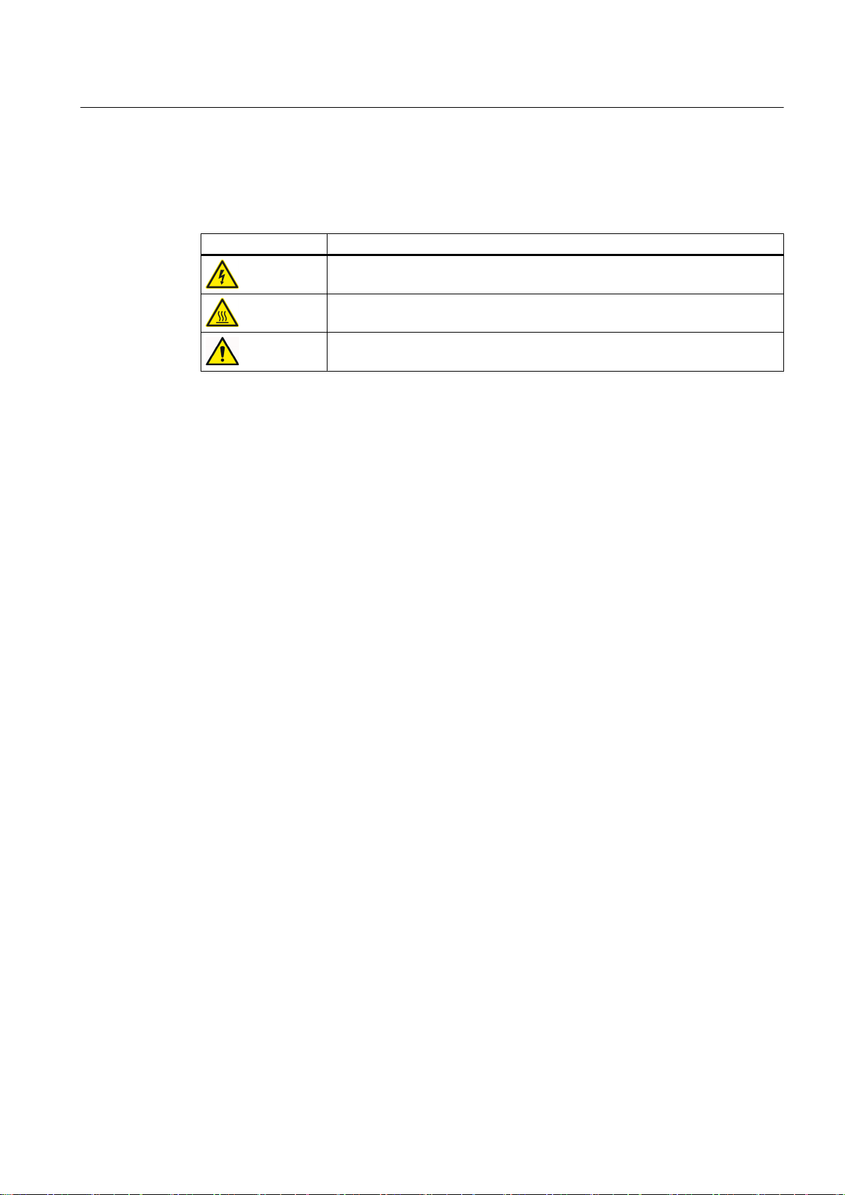
1.3 Warning symbols on the device
Please observe the warning symbols attached to the device. The warning symbols have the
following meaning:
Warning symbol Meaning
Warning: Voltage
Warning: Hot surface
General warning symbol: Observe the explanations about the hazard on the
device labels.
For transportation, observe the "transportation markings" on the device packaging.
Introduction
1.3 Warning symbols on the device
SINAMICS PERFECT HARMONY GH180 6SR41 manufactured in NMA Nuernberg, Germany
Operating Instructions Rev.201706301306 19
Introduction
1.4 Introduction
1.4 Introduction
About This Manual
This manual provides customer documentation for the SINAMICS PERFECT HARMONY
GH180 Variable Frequency Drive (VFD).
The content of this manual provides standard information as well as descriptions of all available
options for this product line. The contents also provides safety warning and notes, preparation
for use, assembly/installation, electrical, commissioning, operation, maintenance, spare parts,
and disposal information. The latter pages of this manual contain appendices for specific
technical documents, support services information, technical drawings, and other relevant data.
This manual is intended for use by trained personnel having unique job functions and
qualifications since there are areas on the VFD that are hazardous and therefore may cause
death or serious bodily harm to personnel and also cause serious damage to the Drive.
The manual is also intended for use by planners, project engineers, installation personnel,
programmers, commissioning personnel, operators, service and maintenance personnel.
This documentation contains the most important safety-related information for the SINAMICS
PERFECT HARMONY GH180 VFD. It is important supplementary information, but is not a
replacement for the operating instructions nor the other product documentation on your CD.
WARNING
Familiarity with the Product Documentation
Only the complete product documentation will allow you to assemble and install the
equipment, to put it into operation and to maintain it correctly and safely.
Incorrect work on the equipment can result in death, severe injury or material damage.
Always refer to the operating instructions when working on the equipment. You will find the
operating instructions and other equipment information about your product that you will need
on the CD supplied with the Drive.
Variable Frequency Drive Introduction
A variable frequency drive (VFD) system controls the rotational speed and torque of an
alternating current (AC) electric motor by adjusting the frequency and voltage of the electrical
power supplied to the motor. In an AC motor, frequency determines the motor speed.
SINAMICS PERFECT HARMONY GH180 6SR41 manufactured in NMA Nuernberg, Germany
20 Operating Instructions Rev.201706301306

Safety Notes
2.1 General Safety Information
Proper Use
SINAMICS PERFECT HARMONY GH180 medium voltage drives must always be installed in
closed electrical operating areas. The drive is connected to the industrial network via a circuitbreaker.
The specific transport conditions must be observed when the equipment is transported. The
equipment shall be assembled/installed and the separate cabinet units connected properly by
cable and/or busbar in accordance with the assembly/installation instructions. The relevant
instructions regarding correct storage, EMC-compliant installation, cabling, shielding and
grounding and an adequate auxiliary power supply must be strictly observed. Fault-free
operation is also dependent on careful operation and maintenance.
The power sections are designed for variable-speed drives use with synchronous and
asynchronous motors. Operating modes, overload conditions, load cycles, and ambient
conditions different to those described in this document are allowed only by special
arrangement with the manufacturer.
Commissioning should only be carried out by trained service personnel in accordance with the
commissioning instructions.
2
See also
System components such as circuit-breaker, transformer, cables, cooling unit, motor, speed
sensors, etc., must be matched to VFD operation. System configuration may only be carried
out by an experienced system integrator.
Safety instructions for maintenance (Page 145)
SINAMICS PERFECT HARMONY GH180 6SR41 manufactured in NMA Nuernberg, Germany
Operating Instructions Rev.201706301306 21

Safety Notes
2.2 Safety Concept
2.2 Safety Concept
The medium-voltage variable frequency drive (VFD) and its components are subject to a
comprehensive safety concept which, when properly implemented, ensures safe installation,
operation, servicing, and maintenance.
The safety concept encompasses safety components and functions to protect the device and
operators.
The VFD is also equipped with monitoring functions to protect external components.
The VFD operates safely when the interlock and protection systems are functioning properly.
Nevertheless, there are areas on the medium-voltage drive that are hazardous for personnel
and that can cause material damage if the safety instructions described in this section and
throughout the product documentation are not strictly observed.
SINAMICS PERFECT HARMONY GH180 6SR41 manufactured in NMA Nuernberg, Germany
22 Operating Instructions Rev.201706301306
2.3 Observing the Five Safety Rules
There are five safety rules that must always be observed to assure not only personal safety,
but to prevent material damage as well. Always obey safety-related labels located on the
product itself and always read and understand each safety precaution prior to operating or
working on the drive.
The five safety rules:
1. Disconnect the system.
2. Protect against reconnection.
3. Make sure that the equipment is de-energized.
4. Apply grounding means.
5. Cover or enclose adjacent components that are still live.
DANGER
Danger Due to High Voltages
High voltages cause death or serious injury if the safety instructions are not observed or if
the equipment is handled incorrectly.
Safety Notes
2.3 Observing the Five Safety Rules
Potentially fatal voltages occur when this equipment is in operation which can remain present
even after the VFD is switched off.
Ensure that only qualified and trained personnel carry out work on the equipment.
Follow the five safety rules during each stage of the work.
SINAMICS PERFECT HARMONY GH180 6SR41 manufactured in NMA Nuernberg, Germany
Operating Instructions Rev.201706301306 23

Safety Notes
2.4 Safety Information and Warnings
2.4 Safety Information and Warnings
DANGER
Hazardous Voltage!
● Always follow the proper lock-out/tag-out procedures before beginning any maintenance
or troubleshooting work on the VFD.
● Always follow standard safety precautions and local codes during installation of external
wiring. The installation must follow wiring practices and insulation systems as specified in
IEC 61800-5-1.
● Hazardous voltages may still exist within the VFD cabinets even when the disconnect
switch is open (off) and the supply power is shut off.
● Only qualified individuals should install, operate, troubleshoot, and maintain this VFD. A
qualified individual is "a person, who is familiar with the construction and operation of the
equipment and the hazards involved."
● Always work with one hand, wear electrical safety gloves, wear insulated electrical hazard
rated safety shoes, and safety goggles. Also, always work with another person present.
● Always use extreme caution when handling or measuring components that are inside the
enclosure. Be careful to prevent meter leads from shorting together or from touching other
terminals.
● Use only instrumentation (e.g., meters, oscilloscopes, etc.) intended for high voltage
measurements (that is, isolation is provided inside the instrument, not provided by isolating
the chassis ground of the instrument).
● Never assume that switching off the input disconnector will remove all voltage from internal
components. Voltage is still present on the terminals of the input disconnector. Also, there
may be voltages present that are applied from other external sources.
● Never touch anything within the VFD cabinets until verifying that it is neither thermally hot
nor electrically alive.
● Never remove safety shields (marked with a HIGH VOLTAGE sign) or attempt to measure
points beneath the shields.
● Never operate the VFD with cabinet doors open. The only exception is the control cabinet
which contains extra low voltages (ELV).
● Never connect any grounded (i.e., non-isolated) meters or oscilloscopes to the system.
● Never connect or disconnect any meters, wiring, or printed circuit boards while the VFD
is energized.
● Never defeat the instrument’s grounding.
● When a system is configured with VFD bypass switchgear (e.g. contactors between line
and motor, and VFD and motor), these switches should be interlocked so that the line
voltage is never applied to the VFD output if the medium input voltage is removed from
the VFD.
SINAMICS PERFECT HARMONY GH180 6SR41 manufactured in NMA Nuernberg, Germany
24 Operating Instructions Rev.201706301306

Safety Notes
2.4 Safety Information and Warnings
WARNING
Potential Arc Hazard
● Arcing can result in damage to property, serious injury and even death.
● The equipment has not been tested and rated for arc flash protection.
● Avoiding arc hazard risks is dependent upon proper installation and maintenance.
● Incorrectly applied equipment, incorrectly selected, connected or unconnected cables, or
the presence of foreign materials can cause arcing in the equipment.
● Follow all applicable precautionary rules and guidelines as used in working with medium
voltage equipment.
● The equipment may be used only:
– for the applications defined as suitable in the technical description.
– in combination with equipment and components supplied by other manufacturers which
have been approved and recommended by Siemens.
Additional safety precautions and warnings appear throughout this manual. These important
messages should be followed to reduce the risk of personal injury or equipment damage.
WARNING
Obey Rules to Avoid Risk of Death
● Always comply with local codes and requirements if disposal of failed components is
necessary.
● Always ensure the use of an even and flat truck bed to transport the VFD system. Before
unloading, be sure that the concrete pad is level for storage and permanent positioning.
● Always confirm proper tonnage ratings of cranes, cables, and hooks when lifting the VFD
system. Dropping the cabinet or lowering it too quickly could damage the unit.
● Never disconnect control power while medium voltage is energized. This could cause
severe system overheating and/or damage.
● Never store flammable material in, on, or near the drive enclosure. This includes
equipment drawings and manuals.
● Never use fork trucks to lift cabinets that are not equipped with lifting tubes. Be sure that
the fork truck tines fit the lifting tubes properly and are the appropriate length.
SINAMICS PERFECT HARMONY GH180 6SR41 manufactured in NMA Nuernberg, Germany
Operating Instructions Rev.201706301306 25

Safety Notes
2.5 ESD-sensitive Components
2.5 ESD-sensitive Components
Guidelines for Handling Electrostatic Sensitive Devices (ESD)
NOTICE
ESD Sensitive Equipment
● Always be aware of electrostatic discharge (ESD) when working near or touching
components inside the VFD cabinet. The printed circuit boards contain components that
are sensitive to electrostatic discharge. Handling and servicing of components that are
sensitive to ESD should be done only by qualified personnel and only after reading and
understanding proper ESD techniques. The following ESD guidelines should be observed.
Following these rules can greatly reduce the possibility of ESD damage to printed circuit
board (PCB) components.
● Always transport static sensitive equipment in antistatic bags.
● Always use a soldering iron that has a grounded tip. Also, use either a metallic vacuumstyle plunger or copper braid when desoldering.
● Ensure that anyone handling the printed circuit boards is wearing a properly grounded
static strap. The wrist strap should be connected to ground through a 1 Megohm resistor.
Grounding kits are available commercially through most electronic wholesalers.
● Static charge build-up can be removed from a conductive object by touching the object
with a properly grounded piece of metal.
● When handling a PC board, always hold the card by its edges.
● Do not slide printed circuit boards (PCBs) across any surface (e.g., a table or work bench).
If possible, perform PCB maintenance at a workstation that has a conductive covering that
is grounded through a 1 Megohm resistor. If a conductive tabletop cover is unavailable, a
clean steel or aluminum tabletop is an excellent substitute.
● Avoid plastic Styrofoam™, vinyl and other non-conductive materials. They are excellent
static generators and do not give up their charge easily.
● When returning components to Siemens Industry, Inc. always use static-safe packing.
This limits any further component damage due to ESD.
Components that can be destroyed by electrostatic discharge (ESD)
NOTICE
Electrostatic discharge
Electronic components can be destroyed in the event of improper handling, transporting,
storage, and shipping.
Pack the electronic components in appropriate ESD packaging; e.g. ESD foam, ESD
packaging bags and ESD transport containers.
To protect your equipment against damage, follow the instructions given below.
SINAMICS PERFECT HARMONY GH180 6SR41 manufactured in NMA Nuernberg, Germany
26 Operating Instructions Rev.201706301306
Safety Notes
2.5 ESD-sensitive Components
● Avoid physical contact with electronic components. If you need to perform absolutely
essential work on these components, then you must wear one of the following protective
gear:
– Grounded ESD wrist strap
– ESD shoes or ESD shoe grounding strips if there is also an ESD floor.
● Do not place electronic components close to data terminals, monitors or televisions.
Maintain a minimum clearance to the screen (> 10 cm).
● Electronic components should not be brought into contact with electrically insulating
materials such as plastic foil, plastic parts, insulating table supports or clothing made of
synthetic fibers.
● Place components in contact with ESD-suited materials e.g. ESD tables, ESD surfaces,
ESD packaging.
● Measure on the components only if one of the following conditions is met:
– The measuring device is grounded with a protective conductor, for example.
– The measuring head of a floating measuring device has been discharged directly before
the measurement.
The necessary ESD protective measures for the entire working range for electrostatically
sensitive devices are illustrated once again in the following drawings. Precise instructions for
ESD protective measures are specified in the standard DIN EN 61340-5-1.
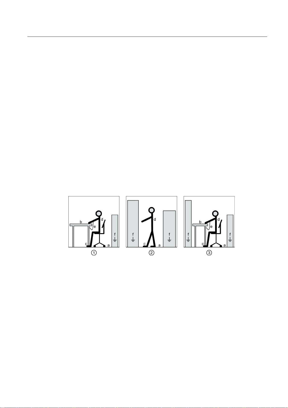
1 Sitting
2 Standing
3 Standing/sitting
a Conductive floor surface, only effective in conjunction with ESD shoes or ESD shoe grounding
strips
b ESD furniture
c ESD shoes or ESD shoe grounding strips are only effective in conjunction with conductive floor‐
ing
d ESD clothing
e ESD wristband
f Cabinet ground connection
Figure 2-1 ESD Protective Measures
SINAMICS PERFECT HARMONY GH180 6SR41 manufactured in NMA Nuernberg, Germany
Operating Instructions Rev.201706301306 27

Safety Notes
2.6 Electromagnetic Fields in Electrical Power Engineering Installations
2.6 Electromagnetic Fields in Electrical Power Engineering Installations
WARNING
Electromagnetic fields "electro smog" when operating electrical power engineering
installations
Electromagnetic fields are generated during operation of electrical power engineering
installations.
Electromagnetic fields can interfere with electronic devices, which could cause them to
malfunction. For example, the operation of heart pacemakers can be impaired, potentially
leading to damage to a person's health or even death. It is therefore forbidden for persons
with heart pacemakers to enter these areas.
The plant operator is responsible for taking appropriate measures (labels and hazard
warnings) to adequately protect operating personnel and others against any possible risk.
● Observe the relevant nationally applicable health and safety regulations. For example, in
Germany, "electromagnetic fields" are subject to regulations BGV B11 and BGR B11
stipulated by the German statutory industrial accident insurance institution.
● Display adequate hazard warning notices on the installation.
● Place barriers around hazardous areas.
● Take measures, e.g. using shields, to reduce electromagnetic fields at their source.
● Ensure personnel are wearing the appropriate protective gear.
SINAMICS PERFECT HARMONY GH180 6SR41 manufactured in NMA Nuernberg, Germany
28 Operating Instructions Rev.201706301306

2.7 Information for nominated persons in control of an electrical installation
2.7 Information for nominated persons in control of an electrical
installation
2.7.1 Security information
Siemens provides products and solutions with industrial security functions that support the
secure operation of plants, systems, machines and networks.
In order to protect plants, systems, machines and networks against cyber threats, it is
necessary to implement – and continuously maintain – a holistic, state-of-the-art industrial
security concept. Siemens’ products and solutions only form one element of such a concept.
Customer is responsible to prevent unauthorized access to its plants, systems, machines and
networks. Systems, machines and components should only be connected to the enterprise
network or the internet if and to the extent necessary and with appropriate security measures
(e.g. use of firewalls and network segmentation) in place.
Additionally, Siemens’ guidance on appropriate security measures should be taken into
account. For more information about industrial security, please visit:
http://www.siemens.com/industrialsecurity
Safety Notes
Siemens’ products and solutions undergo continuous development to make them more secure.
Siemens strongly recommends to apply product updates as soon as available and to always
use the latest product versions. Use of product versions that are no longer supported, and
failure to apply latest updates may increase customer’s exposure to cyber threats.
To stay informed about product updates, subscribe to the Siemens Industrial Security RSS
Feed under:
http://www.siemens.com/industrialsecurity
SINAMICS PERFECT HARMONY GH180 6SR41 manufactured in NMA Nuernberg, Germany
Operating Instructions Rev.201706301306 29

Safety Notes
2.7 Information for nominated persons in control of an electrical installation
SINAMICS PERFECT HARMONY GH180 6SR41 manufactured in NMA Nuernberg, Germany
30 Operating Instructions Rev.201706301306
 Loading...