

Siemens KMS, Flender KMP Series, Flender KMPS Series, Flender KMPP Series Assembly And Operating Instructions Manual
Page 1

Vertical mill gear unit
KMS
Sizes 225 to 850
Assembly and operating instructions
BA 9137 en 12/2015
FLENDER gear units
Page 2

T
echnical data
T
T
1
Vertical mill gear unit
General notes
KMS
Sizes 225 to 850
Assembly and operating instructions
Translation of the original assembly and operating instructions
Safety instructions
ransport and
storage
echnical
description
Fitting
Startup
Operation
2
3
4
5
6
7
8
Faults, causes
and remedy
Maintenance
and repair
Spare parts,
customer service
Declarations
9
10
11
12
BA 9137 en 12/2015
2 / 89
Page 3
Legal notes
Warning note concept
This manual comprises notes which must be observed for your personal safety and for preventing material
damage. Notes for your personal safety are marked with a warning triangle, those only for preventing
material damage appear without a warning triangle. Depending on the level of hazard, the warning notes
are shown in reverse order of seriousness, as follows.
DANGER
means, that death or serious injury will result, if the appropriate preventive action is not taken.
WARNING
means that death or serious injury may result, if the appropriate preventive action is not taken.
CAUTION
means that a slight injury may result, if the appropriate preventive action is not taken.
NOTICE
means that material damage may result, if the appropriate preventive action is not taken.
Where there is more than one hazard level, the warning note for whichever hazard is the most serious is
always used. If in a warning note a warning triangle is used to warn of possible personal injury, a warning
of material damage may be added to the same warning note.
Qualified personnel
The product or system to which this documentation relates may be handled only by persons qualified for
the work concerned and in accordance with the documentation relating to the work concerned, particularly
the safety and warning notes contained in those documents.
Qualified personnel must be specially trained and have the experience necessary to recognise risks
associated with these products and to avoid possible hazards.
Proper use of Siemens products
Observe also the following:
WARNING
Siemens products must be used only for the applications provided for in the catalogue and the relevant
technical documentation. If products and components of other makes are used, they must be
recommended or approved by Siemens. The faultfree, safe operation of the products calls for proper
transport, proper storage, erection, assembly, installation, startup, operation and maintenance. The
permissible ambient conditions must be adhered to. Notes in the relevant documentations must be
observed.
Trademarks
All designations to which the registered industrial property mark ® is appended are registered trademarks
of Siemens AG. Other designations used in this document may be trademarks the use of which by third
parties for their own purposes may infringe holders’ rights.
Exclusion of liability
We have checked the content of the document for compliance with the hard and software described.
Nevertheless, variances may occur, and so we can offer no warranty for complete agreement. The
information given in this document is regularly checked, and any necessary corrections are included in
subsequent editions.
BA 9137 en 12/2015
3 / 89
Page 4
Foreword
The term "Assembly and operating instructions" will in the following also be shortened to "instructions"
or "manual".
The term
directive 94/9/EC, if the product is put on the market by 19.04.2016, and to the version designed in
conformity to directive 2014/34/EU, if the product is put on the market on or after 20.04.2016.
"2014/34/EU" used in these instructions applies to the version designed in conformity to
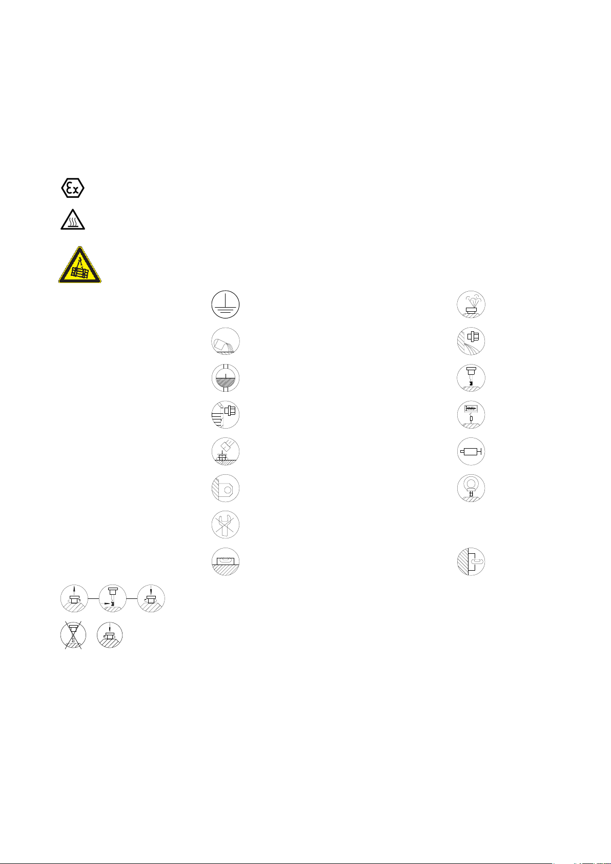
Symbols in these assembly and operating instructions
This symbol additionally indicates an imminent risk of explosion in the meaning of Directive 2014/34/EU.
This symbol additionally indicates an imminent risk of burns due to hot surfaces in the meaning of
standard "DIN EN ISO 137321".
This symbol warns against risks from lifted and/or suspended loads.
Earthconnection point Airrelief point yellow
Oilfilling point
Oil level
yellow Oildraining point white
red Oil level red
Oil level
Lubricating point red Apply grease
Lifting eye Eye bolt
Do not unscrew
Alignment surface, horizontal Alignment surface, vertical
These symbols indicate the oillevel checking procedure using the oil dipstick.
These symbols indicate that the oil dipstick must always be firmly screwed in.
red
Connection for
vibrationmonitoring device
BA 9137 en 12/2015
4 / 89
Page 5

Contents
1. Technical data 8.....................................................
1.1 General technical data 8...............................................................
1.2 Marking of the gear unit designed in accordance with Directive 2014/34/EU 9.................
1.2.1 Ambient temperature 9................................................................
1.3 Measuring-surface sound pressure level 9...............................................
1.4 List of equipment 9....................................................................
2. General notes 10.....................................................
2.1 Introduction 10........................................................................
2.2 Copyright 10..........................................................................
3. Safety instructions 11.................................................
3.1 Obligations of the user 11...............................................................
3.2 Special dangers and personal protective equipment 13......................................
3.3 The five safety rules 14.................................................................
3.4 Environmental protection 14.............................................................
4. Transport and storage 15.............................................
4.1 Content and check of the scope of delivery 15.............................................
4.2 Transport 15..........................................................................
4.3 Storing the gear unit 18.................................................................
4.4 Standard coating and corrosion prevention 18.............................................
4.4.1 Exterior preservation of metallic bright exterior surfaces 20..................................
4.4.1.1 Maximum durability period of the exterior preservation 20....................................
4.4.1.2 Prolongation of the preservation of metallic bright exterior surfaces of the gear unit 20...........
4.4.2 Preservation of the interior of the gear unit 20..............................................
4.4.2.1 Maximum durability period of the interior preservation of the gear unit 20.......................
4.4.2.2 Combined storage/packaging 22.........................................................
4.4.3 Renewal of the interior preservation of the gear unit for longer periods of storage of the gear unit
4.4.3.1 Renewal of the gear unit interior preservation with "Castrol Corrosion Inhibitor N 213" 26.........
4.4.3.2 Renewal of the gear unit interior preservation through complete filling with preservative or
4.4.3.3 Renewal of the interior preservation of the gear unit using the oil- supply system 30.............
that has not been taken into operation yet 26...............................................
operating oil. 28.......................................................................
5. Technical description 32..............................................
5.1 General description 32.................................................................
5.2 Delivery condition of the gear unit 32.....................................................
5.3 Lubrication 33.........................................................................
5.3.1 Hydrodynamic lubrication of the axial tilting pad thrust bearings 33............................
5.3.2 Hydrodynamic lubrication of the axial tilting pad thrust bearings in gear units
5.3.3 Hydrodynamic lubrication of the axial tilting pad thrust bearings with radial piston pump 34.......
5.3.4 Labyrinth seals 34.....................................................................
5.4 Drive coupling 35......................................................................
5.5 Heating 35............................................................................
5.6 Heating element on ex-version 36........................................................
5.6.1 Oil level monitoring of the heating elements 36.............................................
5.7 Indication of oil level 36.................................................................
5.8 Oil temperature monitoring 37...........................................................
5.9 Oil level monitoring system 37...........................................................
with hydrostatic start-up assistance 33....................................................
BA 9137 en 12/2015
5 / 89
Page 6

6. Fitting 38.............................................................
6.1 General assembly information 38........................................................
6.2 Set-up conditions 39...................................................................
6.2.1 Dimensions and weights 39.............................................................
6.2.2 Lifting device 39.......................................................................
6.3 Preparatory measures for gear unit installation 40..........................................
6.3.1 Maintaining preservation if the gear unit has been opened in the meantime 41..................
6.3.2 Foundation 42.........................................................................
6.4 Assembly of the gear unit 42............................................................
6.5 Installing the pipework 43...............................................................
6.6 Pickling of adapted pipes 43.............................................................
6.7 Installing the couplings 44...............................................................
6.8 Installing the motor 45..................................................................
6.9 Assembly of loose add-on parts included in the delivery 46..................................
6.10 Welding work on the mill 46.............................................................
6.11 Final work 47..........................................................................
6.12 Screw connection classes, tightening torques and initial stressing forces 47....................
6.12.1 Screw connection classes 47............................................................
6.12.2 Tightening torques and initial stressing forces 48...........................................
7. Start-up 50...........................................................
7.1 Procedure before start-up 50............................................................
7.1.1 Removal of preservative agent from exterior 50............................................
7.1.2 Removal of preservative agent from interior 51.............................................
7.1.3 Draining preservative oils 53............................................................
7.1.4 Flushing before initial start-up 54.........................................................
7.1.4.1 Oil quantity for flushing 54...............................................................
7.1.5 Fill in operating oil 54...................................................................
7.1.5.1 Oil level 55............................................................................
7.1.5.2 Procedure for filling 55..................................................................
7.1.6 Oil-supply system 57...................................................................
7.1.7 Checks before start-up 57...............................................................
7.2 Start-up 59...........................................................................
7.2.1 Pre-lubrication phase 59................................................................
7.2.2 Initial start-up 59.......................................................................
7.2.3 Checking procedure 60.................................................................
7.3 Removal from service 60...............................................................
7.3.1 Renewal of the gear unit interior preservation on gear units having already been in operation 61...
7.3.1.1 Renewal of the interior preservation of the gear unit using the oil- supply system 61.............
7.3.1.2 Renewal of the gear unit interior preservation with "Castrol Corrosion Inhibitor N 213" 63.........
7.3.1.3 Renewal of the gear unit interior preservation through complete filling with preservative
7.3.2 Exterior corrosion prevention 66.........................................................
or operating oil 65......................................................................
8. Operation 67.........................................................
8.1 General 67............................................................................
8.2 Oil level 68............................................................................
8.3 Irregularities 68........................................................................
9. Faults, causes and remedy 70.........................................
9.1 General information on faults and malfunctions 70..........................................
9.2 Faults, causes and remedy 71...........................................................
BA 9137 en 12/2015
6 / 89
Page 7

10. Maintenance and repair 74............................................
10.1 General notes on maintenance 74........................................................
10.2 Clean the gear unit 75..................................................................
10.3 Clean the air filter 75...................................................................
10.3.1 Replacing the air filter cartridge 76.......................................................
10.4 Flushing 76...........................................................................
10.5 Oil filling 76...........................................................................
10.6 Inspection 77.........................................................................
10.7 Maintenance 78.......................................................................
10.7.1 Examine water content of oil, conduct oil analyses 79.......................................
10.7.2 Change oil 80.........................................................................
10.7.3 Check tightness of screw connections 82.................................................
10.8 Welding work on the mill 82.............................................................
10.9 Vibration measurements 83.............................................................
10.10 Repair 84.............................................................................
10.11 General inspection of the gear unit 85.....................................................
10.12 Lubricants 85.........................................................................
11. Spare parts, customer service 86......................................
11.1 Stocking spare parts 86.................................................................
11.2 Addresses for ordering spare parts and customer service 86.................................
12. Declarations 87.......................................................
12.1 Declaration of incorporation 87..........................................................
12.2 EU declaration of conformity 88..........................................................
BA 9137 en 12/2015
7 / 89
Page 8
1. Technical data
1.1 General technical data
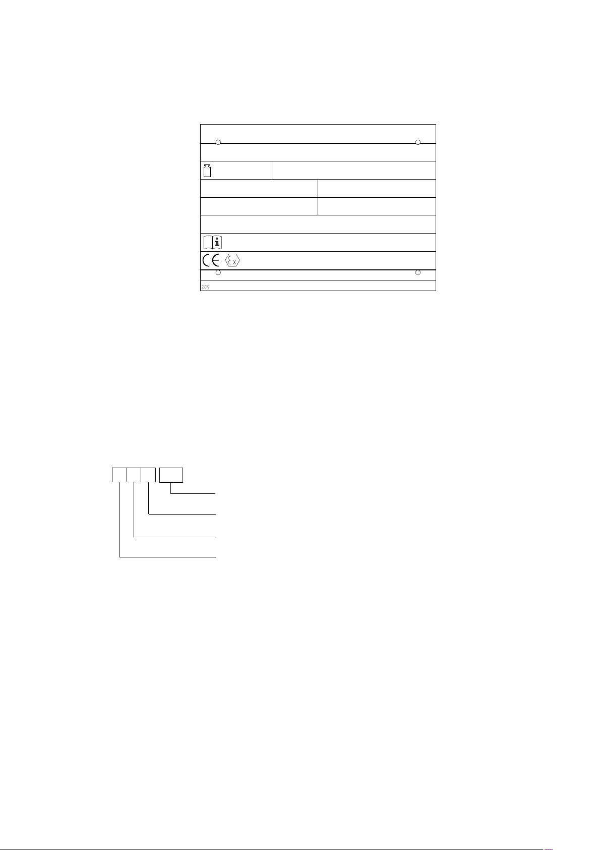
The most important technical data are shown on the rating plate. These data and the contractual
agreements between Siemens and the customer for the gear unit determine the limits of its correct use.
①
②
③
⑤
⑦
⑨
⑩
(see item 1.2)
⑪
⑫
Fig. 1: ATEX Rating plate on gear unit
① Company logo
② Serial number
#)
③ Total weight (without oil filling) in kg
④ Special information
⑤ Type, size
⑥ Power rating P
#)
Production site code / Order no. item seq. no. / Year built
*)Example
*)
in kW or torque T2 in Nm
2
④
⑥
⑧
⑦ Rotation speed n
⑧ Rotation speed n
1
2
in min
in min
-1
-1
⑨ Oil data (oil type, oil viscosity, oil quantity)
⑩ Instruction manual numbers
⑪ Manufacturer and place of manufacture
⑫ Country of origin
KMS
For details regarding weight and further technical data, refer to the drawings in the gear unit documentation
and the order-specific data sheet.
225
Size 225 … 850......................
Model S = Spur wheel section.....................
Area of use M = Vertical mill................
Gear unit type K = Bevel gear unit..............
BA 9137 en 12/2015
8 / 89
Page 9

1.2 Marking of the gear unit designed in accordance with Directive 2014/34/EU
Table 1: ATEX identification for above-ground applications
Equipment
group
II 3 Dust (D) - -
1)
T
a min.
T
a min.
T
a max.
T
a
Equipment
category
≤ Ta ≤ T
Explosive
Atmosphere
= permissible ambient temperature range in °C:
a max.
= minimum permissible ambient temperature
= maximum permissible ambient temperature
= symbol for ambient temperature
Note
The ignition protection type "b" is not available for gear units without electrical explosion hazard
monitoring device (e. g. temperature, oil level).
The rating plate on the gear unit indicates the marking for the applicable case of application.
1.2.1 Ambient temperature
The specifications of Directive2014/34/EU apply to the ambient temperature range of from
- 20 °C to + 40 °C. By adopting various suitable measures, the gear unit may be used in ambient
temperatures from - 40 °C to + 60 °C. However, the temperature range and the expanded temperature
range must generally be approved by Siemens and be specified in the order text.
In individual cases the permissible ambient temperature range specified on the rating plate always applies.
1.3 Measuring-surface sound pressure level
Explosion
group
Temperature
class
Mark
II 3 D 120 °C bck Ta..
1)
A measuring-surface sound pressure level during operation cannot be specified, as the gear unit is
operated without load during the test run on the Siemens test bench.
1.4 List of equipment
Note
All important accessory components are specified in the order specific equipment list including your
technical data.
BA 9137 en 12/2015
9 / 89
Page 10

2. General notes
2.1 Introduction
These instructions are a part of the gear unit delivery and must always be kept on hand near the gear unit.
NOTICE
Property damage
Damage to the gear unit or occurrence of operating failures is possible.
All persons carrying out work on the gear unit must have read and understood the instructions and must
adhere to them.
Siemens accepts no responsibility for damage or disruption caused by disregard of these instructions.
The "FLENDER Bevel-helical gear unit" of the type "KMS" described in these instructions has been
designed for driving a vertical mill.
The gear unit is designed only for the application specified in the order-specific gear unit documentation.
Deviating operating conditions require new contractual agreements.
The gear unit is manufactured in accordance with the state of the art and is delivered in a condition ready
for safe and reliable use. The gear unit complies with the requirements in Directive 2014/34/EU.
The gear unit may only be used and operated in accordance with the conditions laid down in the service
and supply contract concluded between Siemens and the customer.
The gear unit described in these instructions conforms to the state of technical development at the time
when these instructions went to print.
In the interest of technical further development we reserve the right to make changes to the individual
assembly groups and accessory parts as we deem appropriate in order to increase their capacity and
safety while maintaining their essential characteristics.
2.2 Copyright
The copyright to these instructions is held by Siemens AG.
These instructions may be used neither in full nor in part for competitive purposes nor be made available
to third parties without our approval.
Technical enquiries should be directed to our factory or to one of our customer service centres:
Siemens AG
Am Industriepark 2
46562 Voerde
Tel.: +49 (0)2871 / 92‐0
Fax: +49 (0)2871 / 92‐1544
BA 9137 en 12/2015
10 / 89
Page 11
3. Safety instructions
WARNING
Risk of falling
Serious injury from falling is possible.
The gear unit and its add-on parts must not be accessed during operation.
The gear unit may only be accessed for maintenance and repair works during standstill of the gear unit.
WARNING
Risk of injury from changes made on own initiative
Changes made on own initiative are prohibited.
This also pertains to the protection equipment that is installed as contact protection.
3.1 Obligations of the user
• The operator must ensure that everyone carrying out work on the gear unit has read and understood
these instructions and is adhering to them in every point in order to:
─ avoid injury or damage to the user and third parties,
─ ensure the safety and reliability of the gear unit,
─ avoid loss of use and environmental damage caused by incorrect use.
• During transport, assembly, installation, demounting, operation and maintenance of the unit, the
relevant safety and environmental regulations must be observed at all times.
• The gear unit may only be operated, maintained and/or repaired by persons qualified for the work
concerned (see "Qualified personnel" on page 3 of this manual).
• The outside of the gear unit must not be cleaned with high-pressure cleaning equipment.
• All work must be carried out with great care and due regard for safety.
DANGER
Danger to life from switched on system
For carrying out work on the gear unit, the gear unit and an added on or separate oil-supply system must
generally be set in standstill.
The drive unit must be secured against accidental start-up (e.g. by locking the key switch or removing
the fuses from the power supply).
Attach a notice on the start switch stating clearly that work is in progress on the gear unit.
At the same time, the complete system must be free from load so that no danger is caused during the
disassembly work.
• No welding work may be done at all on the drive.
The drive systems must not be used as an earthing point for electric-welding operations. Toothed parts
and bearings can be irreparably damaged by welding.
BA 9137 en 12/2015
11 / 89
Page 12
NOTICE
Property damage
Damage to the gear unit is possible.
For gear units, which are operated together with electrical machines that generate power or that are
supplied with power (e. g. motors, generators, etc.), it must be ensured that no current can flow through
the gear unit. The flow of current can lead to irreparable damages on rolling bearings and gear teeth.
Flow of current can arise, e. g. through short circuits, flash arcs, conductive dust layers, etc.
Suitable measures may be:
– Use of isolators
– Earth the gear unit professionally
DANGER
Electrostatic discharge
Danger to life from ignition of present explosive atmosphere by electrostatic discharge.
A potential equalisation in accordance with the applying regulations and directives must be carried out.
Threaded holes for an earth connection are provided on the gear units or on the output flange. This work
must always be done by trained electricians.
NOTICE
Property damage
Damage to the gear unit is possible.
Immediately stop the gear unit by turning off the drive unit when inexplicable changes are noticed
during the operation, such as a significantly increased operating temperature or changed sounds of
the gear unit.
DANGER
Danger to life from rotating and/or moving parts
Risk of being gripped or drawn in by rotating and/or moving parts.
Rotating and/or movable drive parts must be provided with suitable safeguards to prevent contact.
Note
When the gear unit is incorporated in plant or machinery, the manufacturer of such plant or machinery
must ensure that the requirements, notes and descriptions contained in these instructions are
incorporated in its own instructions.
DANGER
Explosion hazard
Danger to life from ignition of present explosive atmosphere by use of unsuitable add-on parts.
All add-on parts must satisfy the requirements in Directive 2014/34/EU.
Simple electrical means (such as monitoring devices, switches, Pt100 measuring resistance) without
identification in accordance with Directive 2014/34/EU must be connected intrinsically safe by means
of suitable isolation amplifiers.
BA 9137 en 12/2015
12 / 89
Page 13
DANGER
Electrostatic discharge
Danger to life from ignition of present explosive atmosphere by electrostatic discharge.
The coating must not carry an electrostatic charge.
The operator must ensure that highly effective mechanisms which can set up a charge in the coating
are safely avoided.
• Removed safeguards must be refitted prior to starting up.
• Notices attached to the gear unit, such as rating plate and direction arrow, must always be observed.
They must be kept free from dirt and paint at all times. Missing plates must be replaced.
• Screws which have been damaged during assembly or disassembly work must be replaced with new
screws of the same strength class and type.
• Spare parts must be obtained from Siemens (see section 11. "Spare parts, customer service").
3.2 Special dangers and personal protective equipment
Depending on operating conditions, the surface of the gear unit may develop extreme temperatures.
WARNING
Risk of burns
Serious injury caused by burns on hot surfaces (> 55 °C) is possible.
Wear suitable protection gloves and protection clothing.
WARNING
Risk of low temperatures
Serious injury from cold damage (pain, numbness, frostbites) on cold surfaces (< 0 °C) is possible.
Wear suitable protection gloves and protection clothing.
WARNING
Risk of scalding
Serious injury from discharging hot operating media is possible when these are changed.
Wear suitable protection gloves, protection glasses and protection clothing.
WARNING
Risk of eye injury
Small foreign matter such as sand or dust can get into the cover plates of the rotating parts and might
be thrown back by these.
Wear suitable protective glasses.
BA 9137 en 12/2015
13 / 89
Page 14

Note
In addition to any generally prescribed personal protection equipment (protection shoes, protection
clothing, helmet, etc.) handling the gear unit requires wearing suitable safety gloves and suitable
safety glasses.
Note
The gear unit complies with the requirements in Directive 2014/34/EU.
DANGER
Explosion hazard
Danger to life from ignition of a present explosive atmosphere is possible when carrying out assembly
or disassembly works on the gear unit.
The gear unit must not be assembled or disassembled in an explosive environment.
3.3 The five safety rules
For your personal safety as well as avoidance of property damages, please always observe the safety
notices and the following five safety rules pursuant to the standard "DIN EN 50110-1" (Operations in
powered-down condition) when working on the electrical components of the system. Apply the five safety
rules from the start of the work on the machine, in the order cited above.
1) Disconnect
Also disconnect the auxiliary currents, e. g. standstill heating.
2) Secure against re-connection.
3) Verify that disconnected parts are have zero voltage.
4) Earth and short-circuit.
5) Cover or shield adjacent live parts.
Upon completion of the work, undo the taken measures in the reverse order.
3.4 Environmental protection
• Existing packaging material must be disposed of in accordance with the regulations or be given to
recycling.
• When changing oil, the used oil must be collected in suitable containers. Remove any pools of oil
immediately using an oil binding agent.
• Preservative agents should be stored separately from used oil.
• Used oil, preservative agents, oil binding agents and oil-soaked cleaning cloths must be disposed of
in accordance with environmental regulations.
• Disposal of the gear unit after its service life:
─ Drain all operating oil, preservative agent and/or cooling agent from the gear unit and dispose of it
in accordance with the regulations.
─ Depending on the national regulations, gear unit components and/or add-on parts may have to be
disposed of separately or be given to recycling.
BA 9137 en 12/2015
14 / 89
Page 15
4. Transport and storage
Observe the instructions in section 3. "Safety instructions"!
4.1 Content and check of the scope of delivery
The content of the delivery is listed on the packing slip. The completeness of the scope of delivery must
be checked against the packing slip directly on receipt. The packaging must not be opened for the check.
Damages on packaging and/or items missing from the package must be reported to Siemens in writing
within 2 weeks.
NOTICE
Property damage
Damage to the gear unit from corrosion is possible.
The packaging must not be opened in any case. Otherwise, the durability period of the gear unit
preservation will reduce.
Note
If the packaging is opened nonetheless, section 4.4 must be observed.
WARNING
Serious personal injury can be caused by a defective product
If there is any visible damage, the gear unit must not be taken into operation.
4.2 Transport
Note
The product weight is indicated on the rating plate.
DANGER
Danger to life
Danger to life from load falling down due to deficient attachment.
Do not stay underneath suspended loads.
When attaching, lifting, lowering and shifting the load, pay attention to the following:
– Observe the load limits
– Proper fastening of the attachment equipment
– Centre of gravity possibly being off centre
– Even load distribution on load-bearing equipment with multiple load hook-ups
– Low process speed
– Oscillating the load and/or attaching the load to objects
or building parts is prohibited.
– Load hooks may not be loaded at their tip
– Set down products only on even, non-slipping and stable underground
BA 9137 en 12/2015
15 / 89
Page 16
WARNING
Risk of crushing
Risk of being crushed by a transported component when the used lifting gear and load-bearing
equipment is not suitable and the component comes loose.
Attach the product for transport only on the marked attachment points. Lifting gear and load equipment
must be used that has adequate load-bearing capacity.
Observe the notes regarding load distribution on the packaging.
When being lifted the product must be transported slowly and carefully in order to avoid personal injury
and damage to the gear unit.
For example, impact on free shaft ends might lead to damage on the gear unit.
Gear units provided with pipework must be transported with particular care.
The gear unit is delivered in a fully assembled condition. If applicable, additional items are delivered
packaged separately.
Depending on the size of the unit and transport route, the gear unit will have different types of packaging.
Unless agreed otherwise by contract, the packaging complies with the Packaging Guidelines of the HPE
(Federal Association of Wood Packaging, Pallets, Export Packaging).
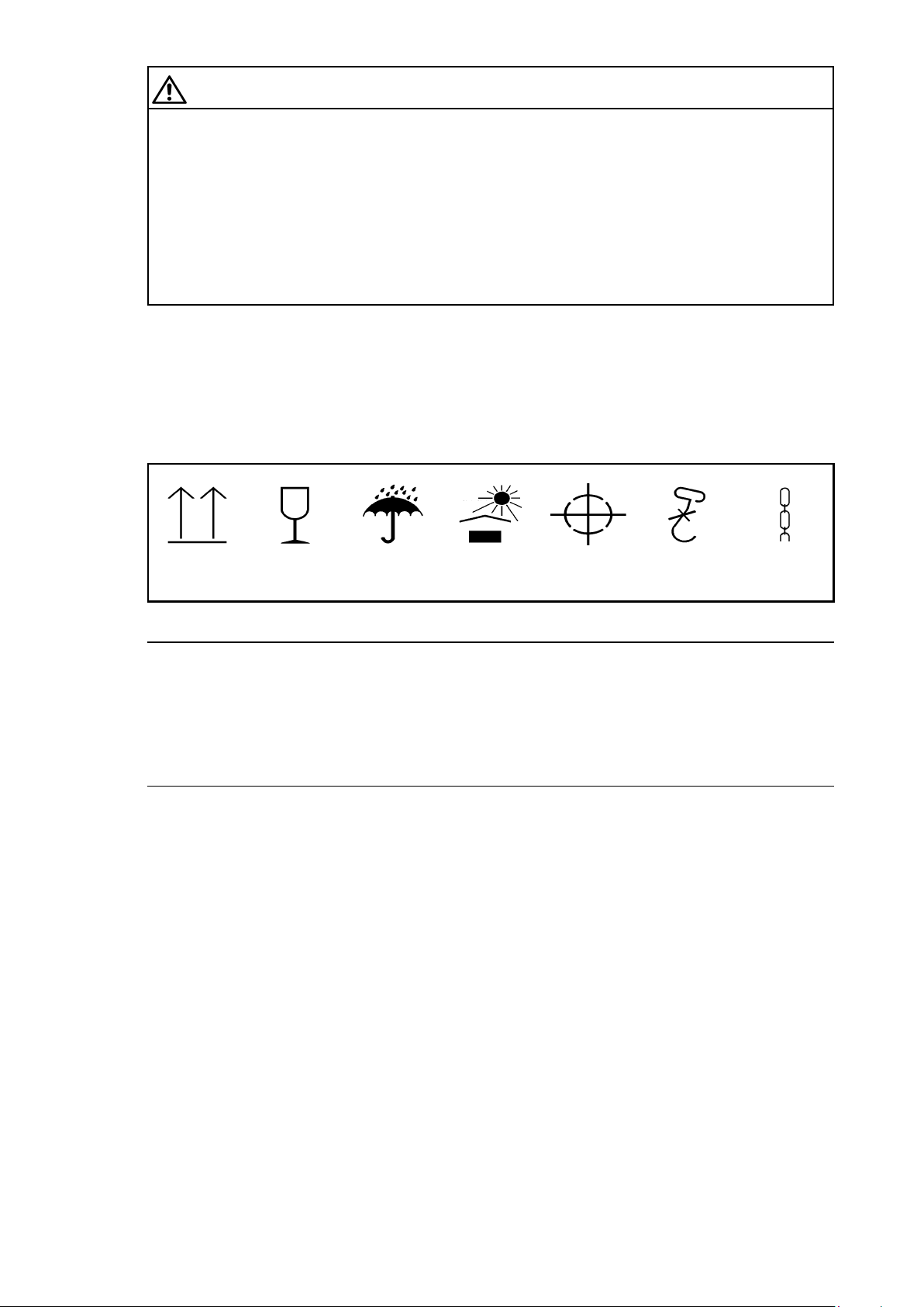
The symbols marked on the packaging must be observed at all times. These have the following meanings:
Top Fragile Keep dry Keep cool Centre of
gravity
Use no hand
hook
Attach
here
Fig. 2: Transport symbols
Note
The gear unit may only be transported by means of transport equipment suitable for this purpose.
The gear unit should be transported without oil filling and be kept in/on the transport packaging.
If the gear unit is in seaworthy packaging (wooden box), the attachment points marked on the
packaging have to be used.
If the gear unit is delivered without seaworthy packaging, the attachment points as shown in Figure 3
have to be used.
BA 9137 en 12/2015
16 / 89
Page 17
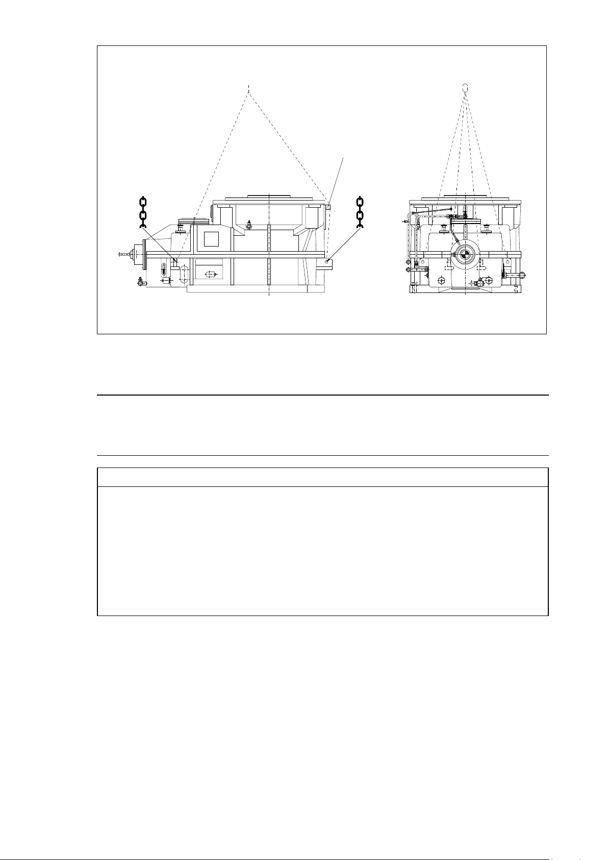
1
Fig. 3: Alternative attachment points
1 Wooden block
Note
The detailed illustration of the gear unit, the position of the attachment points, and the positioning of
the wooden blocks for the protection of the gear unit during transport can be found on the dimensioned
and transport drawings in the order-specific gear unit documentation.
NOTICE
Property damage
Damage to the gear unit is possible when using the wrong attachment points. Use only the lifting eyes
provided to attach lifting gear to the unit. Attach slings with shackles to the eyebolts.
Transporting of the gear unit by attaching it to the pipework is not permitted.
The pipework must not be damaged.
Do not use the front threads at the shaft ends to attach slinging and lifting gear for transport.
Slinging and lifting gear must be adequate for the weight of the gear unit.
To prevent the housing, output flange and pipework from being damaged by the deflection of the
transport rope, wooden blocks must be placed under the rope.
The output flange of the gear unit must never be lifted.
BA 9137 en 12/2015
17 / 89
Page 18
4.3 Storing the gear unit
The gear unit must be stored with a cover, placed on a vibration-free dry base in a sheltered place, in the
position of the original packaging or in the position of use. Any storage methods deviating from this affect
the durability period of the gear unit preservation (see item 4.4).
NOTICE
Property damage
Any damage to the coating may cause the failure of the exterior protective coating and consequently
lead to corrosion.
When temporarily storing the gear unit and any components supplied with it, the applied corrosion
protection has to be preserved.
Ensure that the coat is not damaged.
DANGER
Danger to life from the gear unit toppling or dropping
Risk of being crushed or struck by a gear unit toppling or dropping.
Do not stack gear units on top of one another.
NOTICE
Property damage
Damage to the gear unit by deposit of foreign matter or moisture. If the gear unit is stored outdoors, it
must be covered particularly carefully and it must be ensured that neither moisture nor foreign material
can collect on the unit.
Waterlogging must be avoided.
NOTICE
Property damage
Damage to the gear unit from external effects.
Unless agreed otherwise by contract, the gear unit must not be exposed to harmful effects, such as
chemically aggressive products.
Special environmental conditions during transport (e.g. transport by ship) and storage (climate,
termites) must be agreed on by contract.
4.4 Standard coating and corrosion prevention
The gear unit is to be provided with interior preservation on delivery (see "Technical data" in the gear unit
documentation prepared specifically for the order), and the free shaft ends are to be provided with
protective preservation (see Table 2 in item 4.4.1.1).
The properties of the exterior preservation when using a Siemens standard priming are resistant to:
─ weak acids and alkalis
─ solvents
─ weathering, also tropical
─ temperatures up to 120 °C / 248 °F (for short periods up to 140 °C / 284 °F)
If a different exterior coating is intended by the customer (contrary to the Siemens standard), the protection
of the external coating will be within the customer's responsibility.
BA 9137 en 12/2015
18 / 89
Page 19
NOTICE
Property damage
Damage to the gear unit from corrosion is possible.
The gear unit is normally delivered completely ready with a priming and a finishing coat.
Where gear units are delivered with a priming coat only, it is necessary to apply a finishing coat
according to the standard procedures relevant for the specific application.
The priming coat alone is not suitable to provide sufficient long-term corrosion protection.
Note
The coating complies with the requirements for the conductivity of the coating and the limitation of the
layer thickness of the applied coating according to the standard "DIN EN 13463-1". Electrostatic
charging is not expected if coatings have a thickness of <200µm. Where gear units are delivered with
a priming coat only, it is necessary to apply a finishing coat according to the standard procedures
relevant for the specific application.
The priming coat alone is not suitable to provide sufficient long-term corrosion protection.
DANGER
Electrostatic discharge
Danger to life from ignition of present explosive atmosphere by electrostatic discharge.
The coating must not carry an electrostatic charge.
The operator must ensure that highly effective mechanisms which can set up a charge in the coating
are safely avoided.
Note
Examples of highly effective charge-generating mechanisms are:
– the rapid passage of heavily dust-laden air near by
– the sudden escape of particle-laden compressed gases
– other heavy friction action (not manual cleaning or rubbing with cleaning cloths)
NOTICE
Property damage
Any damage to the coating may cause the failure of the exterior protective coating and consequently
lead to corrosion.
Ensure that the coat is not damaged.
Note
Corrosion prevention durations of the interior preservation depend on the kind of transport, type of
packaging and the place of installation and/or storage (see Table 3 in item 4.4.2.1).
The durability period of the exterior preservation and the related requirements can be found in Table 2
under item 4.4.1.1.
The warranty starts upon notification of readiness for delivery (see "Technical data" in the gear unit
documentation). The provided interior gear unit preservation is also shown in "Technical data".
When storing differently from the durability periods of preservation as specified in Tables 2 and 3
applicable for the gear unit, the interior preservation must be prolonged (see item 4.4.3) and if necessary,
the exterior preservation must be renewed (see item 4.4.1).
Each prolongation of the interior preservation and any renewal of the exterior preservation must be logged.
Note
The record must be kept with these instructions.
BA 9137 en 12/2015
19 / 89
Page 20
4.4.1 Exterior preservation of metallic bright exterior surfaces
4.4.1.1 Maximum durability period of the exterior preservation
Table 2: Durability period for exterior corrosion prevention of shaft ends and other bright machined
surfaces
Durability
of protection
for indoor storage up
to 36 months
for outdoor storage
up to 12 months
1)
The gear unit must be stored with a cover on a vibration-free, dry base in a place sheltered from
1)
2)
Preservative agent
Tectyl 846 K19 approx. 50 µm
Layer thickness Remarks
Long-term wax-based
preservative agent:
– resistant to sea water
– and tropical conditions
– soluble with CH
weathering, in the position of use.
2)
If the gear unit is stored outdoors, it must be covered particularly carefully and it must be ensured that
neither moisture nor foreign material can collect on the unit. Waterlogging must be avoided.
4.4.1.2 Prolongation of the preservation of metallic bright exterior surfaces of the gear unit
In case storage periods exceed the periods specified in Table 2 under item 4.4.1.1, the exterior of the gear
unit must be re-preserved using the preservative agent shown in Table 2.
• Clean the surfaces.
• Apply preservative agent (see table 2).
Note
Before start-up, all preservation coats have to be removed from the gear unit according to section 7.1.1.
compounds
4.4.2 Preservation of the interior of the gear unit
4.4.2.1 Maximum durability period of the interior preservation of the gear unit
Table 3 shows the maximum durability of the interior gear unit preservation, depending on the kind of
transport, type of packaging and the setup or storage site.
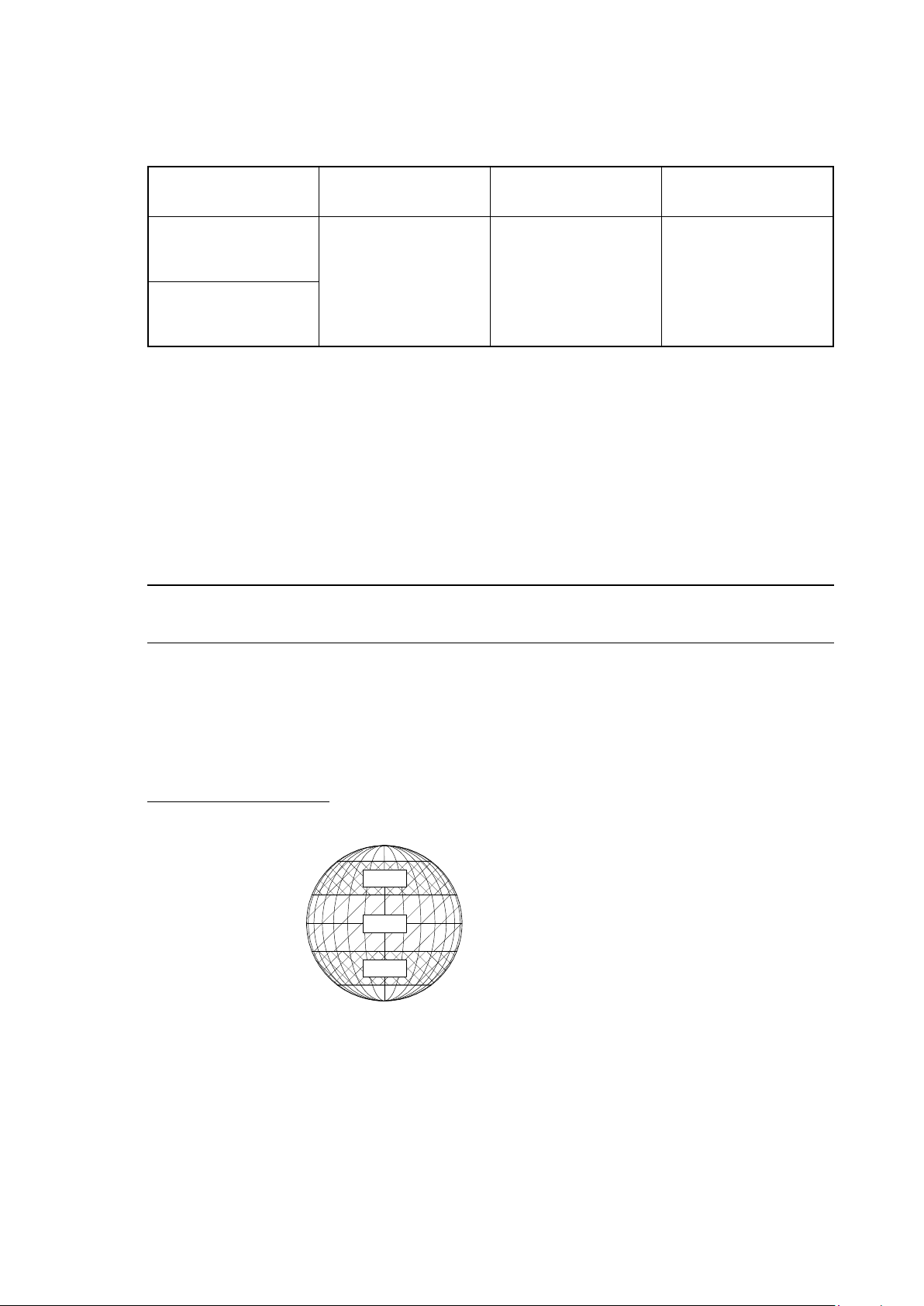
Definition of climatic zones:
North Pole 90°N
Arctic Circle 66.5°N
A
Northern Tropic 23.5°N
B
A
South Pole 90°S
Equator 0°
Southern Tropic 23.5°S
Antarctic Circle 66.5°S
BA 9137 en 12/2015
20 / 89
Page 21

Table 3: Maximum durability period of the interior preservation of the gear unit
Setup and transport
Setup in climatic zone A and at least 50 km
distance from larger bodies of
None or simple
transport packaging
Without sea
transport
salt water
With sea
transport
Transport in
seaworthy
packaging
With or without
sea transport
2)
Storage
Packaging for
storage
Storage place of
packaged unit
maximum durability of the interior gear unit preservation HD (Durability Period)
months
Setup in climatic zone B and/or less than
50 km distance from larger bodies of
None or simple
transport packaging
Without sea
transport
salt water
With sea
transport
Transport in
seaworthy
packaging
With or
without sea
transport
/ HD
1
2)
in
2
No
packaging
covered at
least with
loose tarpaulin
seaworthy
packaging
2)
exposed
outdoors
covered with
loose tarpaulin
under roof
in closed, dry
exposed
outdoors
under roof
in closed, dry
exposed
outdoors
covered with
loose tarpaulin
under roof
in closed, dry
1)
room
1)
room
1)
room
5 3 5 3 3 3
7 3 8 4 3 5
15 3 20 11 3 14
7 3 8 4 3 5
19 3 24 13 3 17
15 3 20 15 3 20
19 3 24 19 3 24
1) under roof:
no direct exposure to sunlight and no direct contact with water
(rain or draining water)
2) Seaworthy packaging:
use of wooden box lined with bitumen paper. The content is sealed in foil and protected against moisture by
addition of drying agents for the prescribed storage period.
Note
On the goods receipt, the seaworthy packaging must be inspected for damages.
If damaged, the packing must be restored to its seaworthy condition.
Note
If different statements were made in agreement with the customer, as to the protective periods on precisely
defined conditions, a description can be found in the order confirmation from Siemens.
BA 9137 en 12/2015
21 / 89
Page 22

4.4.2.2 Combined storage / packaging
If the type of packaging and/or storage is changed within the durability period as HD
to the existing preservation and the present type of packaging and/or storage, a new
determined as the equivalent remaining durability period applicable as of the date of the change. For this
purpose, the following formula has to be used:
LD
HD
LD
HD
HD
HD
If several packaging and/or storage types are combined the following formula must be applied as from
the second change in packaging and/or storage types (
to determine the
= Storage period for the existing preservation
1
= Maximum durability period of the existing preservation
1
2
2äq
according to table 3 in item 4.4.2.1
= Maximum durability period after the change in the type of storage and/or packaging
according to table 3 in item 4.4.2.1
= Maximum remaining durability period after the change in the type of storage and/or
packaging
equivalent remaining durability period applying to the preservation:
HD
n*äq
+ (HD
2äq
+ (1 *
n*1äq
* LD
1
) HD
HD
1
equivalent remaining durability period > HD
n*1
2
) (
HD
, which is applicable
1
HD
2äq
HD
n
)
n*1
has to be
2 äq
)
HD
LD
HD
HD
HD
= Calculated durability period with the previous storage conditions
äq
n-1
= Actual duration of storage with the previous storage conditions
n-1
= Maximum durability period with the present storage conditions
n
n-1
n-
äq
specified in table 2 in item 4.4.2.1
= Maximum durability period with the previous storage conditions
specified in table 2 in item 4.4.2.1
= Remaining durability period after change in the packaging and/or storage types
BA 9137 en 12/2015
22 / 89
Page 23

Example:
─ A gear unit is stored exposed outdoors after sea transport, in climatic zone B, while it is kept in seaworthy
packaging
= 20 months
HD
1
(climatic zone:
for storage: seaworthy packaging, place of storage: exposed outdoors)
B, transport type: sea transport, transport packaging: seaworthy packaging, packaging
─ After 5 months (LD
besides the mill.
HD
= 4 months
2
(climatic zone:
for storage: no packaging, place of storage: covered with loose tarpaulin)
Now, the remaining durability period HD
The remaining durability period of the interior gear-unit preservation after changing the storage type is
3 months.
After one additional month (LD
remaining durability period HD
Given:
), the gear unit is unpacked, covered with a loose tarpaulin, and placed outdoors
1
B, transport type: sea transport, transport packaging: seaworthy packaging, packaging
has to be calculated as follows:
2äq
LD
HD
1
) HD
1
5
) 4
20
2
HD
HD
), the gear-unit is placed outdoors exposed without packaging. Now, the
2
3äq
+ (1 *
2äq
+ (1 *
2äq
HD
is to be calculated as follows:
+ 3months
2äq
HD
LD
HD
HD
HD
The remaining durability period of the interior gear-unit preservation is 1.5 months after combining the
storage types described in the example.
= 3 months (previously calculated)
2äq
= 1 month (actual duration of storage with the previous storage conditions)
2
= 3 months (maximum durability period with the present storage conditions
3
2
n-äq
specified in table 2 in item 4.4.2.1
= 4 months (maximum durability period with the previous storage conditions
specified in table 2 in item 4.4.2.1
= HD
3äq
HD
3äq
HD
+ (HD
3äq
HD
3äq
* LD2) (
2äq
+ (3 * 1) (
+ 1.5months
3
4
)
HD
HD
3
)
2
BA 9137 en 12/2015
23 / 89
Page 24

Table 4: Examples of combined storage (maximally one change in storage) and the resulting remaining
durability of the interior preservation of the gear unit
Original place of storage of the gear
In which climatic zone is the construction site
located?
How was the gear unit packaged for transport? None or simple
How was the gear unit transported? without sea transport with or without sea transport
In what packaging was the gear unit stored at the
construction site?
Where/how was the packed unit stored?
in closed room
or under roof
Setup in climatic zone A and at least 50 km
distance from larger bodies of salt water
Transport packaging
no packaging seaworthy packaging
covered with
1)
loose tarpaulin
in closed room
or under roof
Transport in
seaworthy packaging
1)
Change in place of storage
New
Packaging for
storage
Storage place of
the newly
packaged unit
Change of
original
storage
method after
1 month 4 1/2 4 5 4 1/2
3 months 4 3 4 1/2 4
6 months 3 1 4 3 1/2
Durability period of interior preservation of the gear unit for the new
storage method in consideration of the previous storage period in months
2)
2)
exposed
outdoors
covered with
loose tarpaulin
or
without
packaging
covered with
loose tarpaulin
exposed
outdoors
exposed
outdoors
12 months 1
not permissible,
18 months
1 month 6 1/2 6 7 1/2 7 1/2
3 months 5 1/2 4 7 7
6 months 4 1 6 5 1/2
12 months 1 1/2
18 months
max. durability
period
15 months
not permissible,
max. durability
period
15 months
not permissible,
max. durability
period 7 months
not permissible,
max. durability
period 7 months
not permissible,
max. durability
period 7 months
not permissible,
max. durability
period 7 months
2 1/2 2
1 1/2 1/2
4 3
2 1
BA 9137 en 12/2015
24 / 89
Page 25
Original place of storage of the gear
In which climatic zone is the construction site
located?
How was the gear unit packaged for transport? None or simple
How was the gear unit transported? without sea transport with or without sea transport
In what packaging was the gear unit stored at the
construction site?
Where/how was the packed unit stored?
in closed room
or under roof
Setup in climatic zone B and/or less than 50 km
distance from larger bodies of salt water
Transport packaging
no packaging seaworthy packaging
covered with
1)
loose tarpaulin
in closed room
or under roof
Transport in
seaworthy packaging
1)
Change in place of storage
New
Packaging for
storage
without
packaging
Storage place of
the newly
packaged unit
exposed
outdoors
Change of
original
storage
method after
1 month 2 1/2 2 3 3
3 months 2 1 2 1/2 2 1/2
6 months 1 1/2
12 months
Durability period of interior preservation of the gear unit for the new
storage method in consideration of the previous storage period in months
not permissible,
max. durability
period
11 months
not permissible,
max. durability
period 4 months
not permissible,
max. durability
period 4 months
2 2
1 1/2 1
2)
2)
exposed
outdoors
covered with
loose tarpaulin
or
covered with
loose tarpaulin
exposed
outdoors
not permissible,
18 months
1 month 3 1/2 3 5 5
3 months 3 1 4 1/2 4
6 months 2
12 months
18 months
max. durability
period
11 months
not permissible,
max. durability
period
11 months
not permissible,
max. durability
period
11 months
not permissible,
max. durability
period 4 months
not permissible,
max. durability
period 4 months
not permissible,
max. durability
period
4 months
not permissible,
max. durability
period
4 months
1 1/2
4 3 1/2
2 1/2 2
1 1/2 1/2
1) under roof:
no direct exposure to sunlight and no direct contact with water (rain or draining water)
2) Seaworthy packaging:
use of wooden box lined with bitumen paper. The content is sealed in foil and protected against moisture by
addition of drying agents for the prescribed storage period.
BA 9137 en 12/2015
25 / 89
Page 26

Note
On the goods receipt, the seaworthy packaging must be inspected for damages.
If damaged, the packing must be restored to its seaworthy condition.
Note
If different statements were made in agreement with the customer, as to the protective periods on
precisely defined conditions, a description can be found in the order confirmation from Siemens.
4.4.3 Renewal of the interior preservation of the gear unit for longer periods of storage of the gear unit that has
not been taken into operation yet
If the gear unit is taken into operation at a point in time, when the maximum durability of the interior
preservation of the gear unit exceeds the durability as specified in Table 3 under item 4.4.2.1 or if it has
reached remaining durability period specified in item 4.4.2.2, the interior preservation of the gear unit must
be renewed following the expiration of the durability period.
4.4.3.1 Renewal of the gear unit interior preservation with "Castrol Corrosion Inhibitor N 213"
For the renewal of the gear unit interior preservation, the VCI gas discharging fluid
"Castrol Corrosion Inhibitor N 213" is recommended.
CAUTION
Risk of injury
Risk of injury to eyes or hands from chemically aggressive operating substances.
Wear suitable protection glasses and protection gloves.
Remove any spilled oil immediately using an oil binding agent.
Note
In this renewal of the gear unit interior preservation, it must be ensured that the ambient and gear unit
temperature is above 5 °C during filling.
The following control measures must be taken:
• The pressure, suction and/or return lines are sealed with blind flanges.
• The oil drain cocks on the gear unit and on the tilting pad thrust bearing chamber are sealed with screw
plugs.
• The labyrinth seal on the output flange is sealed with the round cord hollow profile (13) and masked
airtight (see Figure 4 in item 4.4.3.2).
The following procedure is recommended:
• Remove screw plugs that have been screwed in for transport instead of the air filter.
• Fill gear unit with "Castrol Corrosion Inhibitor N 213" through the openings of the air filters.
Filling quantity: 1 litre per cubic metre of the entire free interior volume of the gear unit (to be enquired
from Siemens). The interior volume of the gear unit can be ascertained in approximation also by means
of the length x width x height of the gear unit.
• The vent holes of the air filter for the gear unit have to be closed and sealed again with screw plugs
(these must be replaced again at the start-up).
BA 9137 en 12/2015
26 / 89
Page 27

NOTICE
Property damage
Corrosion is possible when the gear unit is opened for too long.
Close the gear unit airtight again, at the latest one hour after opening.
Table 5 shows the maximum durability period for the preservation renewal with
"Castrol Corrosion Inhibitor N 213" depending on the packaging and setup or storage site. The definition
of climatic zones can be found in item 4.4.2.1.
Note
If the gear unit is transported after the preservation was renewed, the durability period according to
Table 3 in item 4.4.2.1 has to be observed.
Table 5: Maximum durability period of the preservation renewal with
"Castrol Corrosion Inhibitor N 213"
Packaging for
Storage
No
packaging
covered at least
with
loose tarpaulin
seaworthy
packaging
2)
Setup in climatic zone A and at
least 50 km distance from larger
Storage place of
packaged unit
exposed outdoors 5 3
covered with loose
tarpaulin
under roof
in closed,
dry room
exposed outdoors 8 5
under roof
in closed,
dry room
exposed outdoors
covered with loose
tarpaulin
under roof
in closed,
dry room
1)
1)
1)
bodies of
salt water
Maximum durability period of the preservation renewal with
"Castrol Corrosion Inhibitor N 213" (in months)
8 5
20 14
24 17
20 20
24 24
Setup in climatic zone B and/or
less than 50 km distance from
larger bodies of
salt water
1) under roof:
no direct exposure to sunlight and no direct contact with water
(rain or draining water)
2) Seaworthy packaging:
use of wooden box lined with bitumen paper. The content is sealed in foil and protected against moisture
by addition of drying agents for the prescribed storage period.
BA 9137 en 12/2015
27 / 89
Page 28

NOTICE
Property damage
With larger filled-in quantities of the "Corrosion Inhibitor N 213" (above 5 % of the operating oil
quantity), the mixture of operating oil and "Corrosion Inhibitor N 213" must not be used as operating
oil. Before start-up, the remaining "Corrosion Inhibitor N 213" has to be drained and the gear unit must
be flushed thoroughly with operating oil (in this regard, see item 10.4.)
NOTICE
Property damage
Damage to the gear unit is possible.
The gear unit may not be turned.
Note
Before start-up of the gear unit, the measures according to section 7.1 and 7.2 have to be carried out.
4.4.3.2 Renewal of the gear unit interior preservation through complete filling with preservative or operating oil.
A further possibility for renewal of the gear unit interior preservation is to fill the gear unit with preservative
or operating oil until the oil level indicator on the tilting pad thrust bearing chamber shows it is filled
completely with oil.
The durability of this kind of preservation depends on the used oil and has to be enquired with the oil
manufacturer.
For the complete filling, a sealing cap (can be obtained from Siemens) must be mounted on the gear unit
for sealing the input shaft.
The preservation will remain intact for as long as the gear unit remains sealed and the storage durability
of the oil is not exceeded.
Note
Refer to the BA 7300 operating instructions supplied separately for the approved preservative oils. The
viscosity of the operating oil is stated on the rating plate.
For better filling it is recommended to choose an oil with low viscosity, which however is not suitable
for later operation of the gear unit and will thus have to be fully drained. When filling, the filled-in oil
should have a maximum viscosity of 7500 cSt (at VG 320 > 0°C).
For complete filling, also the later operating oil can be used, which has to be drained to the operating
oil level before start-up.
NOTICE
Property damage
Insufficient lubrication due to the incompatibility of the oils.
If the gear unit is preserved with "TRIBOL 1390" (see "Technical data"), it must be flushed before the
complete filling (see BA 7300).
This flushing oil must not be used for operation.
NOTICE
Property damage
Corrosion damages on the gear unit possible from the loss of the preservative effect
Filled gear units can become untight and the gear unit oil might leak. Tightness of the filled gear units
must be monitored. Leaks must be removed. Siemens does not accept any liability for damages that
are caused from leaking gear unit oil during storage.
BA 9137 en 12/2015
28 / 89
Page 29

The following control measures must be taken:
• The pressure, suction and/or return lines (6, 8, 9) are sealed with blind flanges.
• The oil drain cock of the tilting pad thrust bearing chamber (10) is sealed with a screw plug.
• The vent holes for the gear unit (4) are sealed with a screw plug.
• The labyrinth seal of the output flange is sealed with the round cord hollow profile (13) and masked
airtight.
The following procedure is recommended:
• Seal input shaft with a sealing cap (3).
• Seal bottom oil drain of the sealing cap (2) with a screw plug.
• The oil to be filled in must be filtered beforehand with a filter mesh of 25 μm (0.0010 inch).
1
3
2
12
7
10
5
Fig. 4: Gear unit features for preservation measures
13
4
9
8
4
6
1 Breather of sealing cap
2 Oil drain sealing cap
3 Sealing cap
4 Air filter (gear unit)
5 Oil level indicator (gear unit)
6 Suction line (gear unit)
7 Oil drain (gear unit)
8 Pressure line (gear unit)
9 Pressure line (tilting pad thrust bearing
chamber)
10 Oil drain tilting pad thrust bearing
chamber
12 Indication of oil level (tilting pad thrust
bearing chamber)
13 Round cord hollow profile
BA 9137 en 12/2015
29 / 89
Page 30

• Fill sealing cap on the input shaft through the ventilation of the sealing cap (1) The ventilation (1) is to
be closed, only once the oil filling of the gear unit is completed, unless oil is escaping from this opening
before then.
• For filling, remove the sealing cap that seals the oil drain cock of the gear unit (7). The gear unit must
be filled with oil through the bottom oil drain cock of the gear unit (7).
Note
The gear unit will be filled completely only when the oil level indicator on the tilting pad thrust bearing
chamber (12) is filled completely with oil.
• The lower oil drain cock on the gear unit (7) must be provided and sealed with a screw plug.
• If not already done beforehand, close ventilation of the sealing cap (1).
Note
Before the start-up of the gear unit, the measures according to section 7.1 and 7.2 have to be carried
out.
4.4.3.3 Renewal of the interior preservation of the gear unit using the oil- supply system
The prerequisite for this is that the gear unit is still below the mill and connected to the oil-supply system.
"Castrol Alpha SP 220 S" or "Tribol 1390" can be used as preservative agent. The oil level must never be
below the MIN mark on the oil level indicator of the main gear unit, the tilting pad thrust bearing chamber
and/or on the oil-supply system (if the model has a tank, also see the operating manual of the oil-supply
system). For this purpose, the oil-supply system has to be switched on and the gear unit must be turned
without load (at least 1 rotation on the output shaft). The oil must be drained, the gear unit and oil-supply
system be closed, masked and sealed airtight. Air filters have to be replaced for sealing caps and be
sealed. The gear unit has to be sealed airtight with a round cord hollow profile between the gear unit
housing and the output flange. The labyrinth seals on the input shaft and on the output flange must be
masked airtight within 1 hour.
Note
Clean the air filters thoroughly (see item 10.3) and keep it in a safe place (these will be required when
starting up again).
BA 9137 en 12/2015
30 / 89
Page 31

Table 6: Maximum durability period of the interior preservation of the gear unit through operating the
oil-supply system.
Packaging for
Storage
No
packaging
covered at least
with
loose tarpaulin
seaworthy
packaging
2)
Setup in climatic zone A and at
least 50 km distance from larger
Storage place of
packaged unit
exposed outdoors 5 3
covered with loose
tarpaulin
under roof
in closed,
dry room
exposed outdoors 8 5
under roof
in closed,
dry room
exposed outdoors
covered with loose
tarpaulin
under roof
in closed,
dry room
1)
1)
1)
bodies of salt
water
Maximum durability period of the preservation renewal through
operation of the oil-supply system (in months)
8 5
20 14
24 17
20 20
24 24
Setup in climatic zone B and/or
less than 50 km distance from
larger bodies of salt water
1) under roof:
no direct exposure to sunlight and no direct contact with water
(rain or draining water)
2) Seaworthy packaging:
use of wooden box lined with bitumen paper. The content is sealed in foil and protected against moisture
by addition of drying agents for the prescribed storage period.
Note
Before restarting the gear unit, the measures according to section 7.1 and 7.2 have to be carried out.
BA 9137 en 12/2015
31 / 89
Page 32

5. Technical description
Observe the instructions in section 3. "Safety instructions"!
5.1 General description
The gear unit described is a "FLENDER Bevel- helical gear unit" of the type "KMS" designed for driving
a vertical mill.
The axial and radial forces resulting from the grinding process are led into the foundation through the gear
unit housing.
A detailed illustration of the gear unit is contained the drawings in the gear unit documentation.
NOTICE
Property damage
Destruction of the gear unit or gear unit parts from wrong rotation direction is possible.
The gear unit is approved for one direction of rotation only.
Observe the direction-of-rotation arrows on the housing.
5.2 Delivery condition of the gear unit
The input shaft of the gear unit is equipped with a radial shaft sealing ring (1), which is installed hidden and
ensures the necessary airtight sealing of the gear unit interior for the specified preservation period
(see Figure 5). Removing the radial shaft sealing ring during the start-up is not required. Should the radial
shaft sealing ring no longer fulfil its sealing function after start-up, this does not impede the reliability of the
shaft sealing.
A round cord hollow profile (2) is used as sealing between the gear unit housing and the output flange. This
seal additionally serves for the airtight sealing of the gear unit interior for the specified preservation period.
If the gear unit is opened (e.g. by removing the adhesive tape on the labyrinth seal of the input shaft and/or
the output flange, by removing the round cord hollow profile (2) or by opening a lid or screw plug), the
start-up must take place within one week or the gear unit must be re-preserved according to item 4.4.3.
1
2
1 Radial shaft sealing ring 2 Round cord hollow profile
Fig. 5: Arrangement of the round cord hollow profile and radial shaft sealing ring (schematic
illustration)
NOTICE
Property damage
Corrosion is possible when the gear unit is opened too early.
Any opening of the gear unit (e.g. by removing the adhesive tape on the input shaft or on the output
flange, removing the round cord hollow profile, or by opening a lid or a screw plug) reduces the
guaranteed preservation period. If the gear unit is opened, it must be taken into operation within one
week. If the start-up is delayed, special measures are necessary to maintain preservation (see
item 4.4.3).
BA 9137 en 12/2015
32 / 89
Page 33

5.3 Lubrication
The lubrication and cooling is provided by continuous oil circulation through a separate oil-supply system.
To prevent vibration and to compensate for heat expansion, compensators are provided in the pipe
system.
Note
When operating and servicing the components of the oil supply system, observe the operating
instructions of the components.
For technical data, refer to the data sheet and/or the list of equipment.
For a detailed illustration of the gear unit and oil-supply system, refer to the drawings in the gear unit
documentation.
The kind of lubrication can be found on the order-specific equipment list, the lubrication diagram and the
"Technical Data Sheet" of the gear unit.
Depending on the gear unit version, one of the following three lubrication systems is installed in the gear
unit.
Toothed parts and rolling bearings are force-lubricated and cooled through the low-forced lubrication
circuit.
5.3.1 Hydrodynamic lubrication of the axial tilting pad thrust bearings
In low ambient temperatures, the oil must be pre-warmed. If agreed by contract, immersion heaters will be
installed in the gear unit housing or the oil tank, or a separate heating circuit will be provided (see equipment
list and lubrication diagram).
The oil is drawn in by the oil pump, cleaned in the double-changeover filter, which is fitted with an optical
and electrical contamination indicator, then cooled in the cooler and conducted to the lubricating points.
The oil flow is divided by valves and orifice plates or control valves for the lubrication of the gears and tilting
pad thrust bearing.
Volumetric flow, pressure and temperature are constantly monitored by monitoring equipment. To prevent
vibration and to compensate for heat expansion, compensators are provided in the pipe system.
5.3.2 Hydrodynamic lubrication of the axial tilting pad thrust bearings in gear units with hydrostatic start-up assistance
In addition to the hydrodynamic lubrication, part of the oil is fed immediately downstream of the cooler to
the high-pressure pump through a branch circuit.
The high-pressure pump is designed as a radial piston pump and supplies a constant oil quantity at each
connection. The oil is conducted to four axial thrust bearing segments distributed around the
circumference. Before the mill is started, the oil is pumped between the pads and the race. A bearing oil
film will form immediately. After 2 minutes in operation at operating speed, the high-pressure pump must
be turned off.
Pressure switches without pressure transmitter this operating phase and the non-return valves built into
the pads prevent the oil from backing up during normal operation.
BA 9137 en 12/2015
33 / 89
Page 34

5.3.3 Hydrodynamic lubrication of the axial tilting pad thrust bearings with radial piston pump
In addition to the hydrodynamic lubrication, part of the oil is fed immediately downstream of the cooler to
the high-pressure pumps through a branch circuit.
The high-pressure pumps are designed as radial piston pumps and supply a constant oil quantity at each
connection. The same oil quantity is supplied to each bearing pad independently of the counter pressure.
The oil connections are distributed so that no two adjacent pads are supplied by one high-pressure pump.
The drive can continue to be operated throughout the time required for replacing a broken-down
high-pressure pump.
In order to ensure that the high-pressure pumps are operating and no oil line is defective, the oil flows are
monitored for minimum and maximum pressure. The pressure is set through the pressure actually exerted
by the grinding rollers.
If the minimum setting of a pressure- or flow-monitored component is fallen short of, the main drive will be
switched off. If the maximum pressure is exceeded, a warning is given or the main drive is shut off. The
non-return valves built into the pads prevent the oil from backing up during normal operation.
5.3.4 Labyrinth seals
The input shaft and output flange are sealed with labyrinth seals. Air filters are provided on the housing to
regulate the pressure.
Labyrinth seals are non-contacting seals. Labyrinth seals prevent wear and tear on the shaft, are
maintenance-free and ensure favourable temperature characteristics.
1
2
Fig. 6: Labyrinth seal (schematic illustration)
1 Labyrinth seal on output flange 2 Labyrinth seal on input shaft
NOTICE
Property damage
Deficient lubrication is possible from oil leakage on the gear unit.
For reliable operation, labyrinth seals require stationary, horizontal positioning away from dirty water
and high dust concentrations.
Overfilling of the gear unit can cause leakage, as can oil with high foam content.
BA 9137 en 12/2015
34 / 89
Page 35

5.4 Drive coupling
A flexible coupling is to be provided for the gear unit drive. Observe the operating instructions of the
coupling for assembly, operation and maintenance of the coupling.
NOTICE
Property damage
Damage to the gear unit or individual components is possible from inadequate alignment.
When installing the drives, make absolutely certain that the individual components are accurately
aligned to one other. Unacceptable large errors in the alignment of the shaft ends to be connected due
to angular and/or axial misalignments result in premature wear and material damage.
Note
If couplings of other manufacturers are used, the Siemens standard operating instructions for
equivalent couplings provide the minimum requirements for the alignment of the coupling. It cannot be
assured by Siemens whether these minimum requirements are sufficient in any case. If stricter
requirements in the operating instructions of the supplier or similar document are defined, these will
apply.
5.5 Heating
At low temperatures, it may be necessary to heat the gear oil before switching on the drive unit or even
during operation. In such cases, e. g. heating elements can be used. These heating elements convert
electrical energy into heat which is conducted to the surrounding oil. The heating elements are located in
protective tubes inside the housing, thus making it possible to replace them without draining the oil
beforehand.
Heating elements must fully submerge into the oil bath.
The heating elements can be controlled by a resistance thermometer or a temperature monitor, which
emits a signal that is amplified when minimum and maximum temperatures are reached.
A detailed illustration of the gear unit and the position of the add-on parts can found in the drawings of the
gear unit documentation.
DANGER
Explosion and fire hazard
Fire hazard or ignition of an explosive atmosphere by exposed heating rods is possible.
Never switch on the heating elements, unless complete immersion of the heating element in the oil bath
is ensured.
If heating elements are installed afterwards, the maximum heating capacity (see table7) on the outer
surface of the heating element must not be exceeded.
Table 7: Specific heating capacity P
as a function of the ambient temperature
P
Ho
Ambient temperature
(W/cm²)
0.9
0.8
+ 10 to 0
0 to - 25
Ho
°C
0.7
-25 to - 50
Note
Observe the information contained in the relevant operating instructions for operation and
maintenance.
For technical data and control information, refer to the list of equipment.
BA 9137 en 12/2015
35 / 89
Page 36

5.6 Heating element on ex-version
If heating elements are designed explosion-proof, the gear unit is additionally equipped with oil-level
monitoring by means of a level limit switch. This monitoring checks the oil level of the gear unit for the
submersion of the heating rods (see item 5.6.1).
5.6.1 Oil level monitoring of the heating elements
The gear unit is equipped with oil level monitoring. This monitoring system checks the oil level in the gear
unit (minimum oil level for immersion of the heating rods).
The "Oil level too low" signal must be wired so that the heating elements are switched off when the signal
is given. This ensures that the heating elements are not operated if these are not completely immersed.
DANGER
Explosion and fire hazard
Fire hazard or ignition of an explosive atmosphere by exposed heating rods is possible.
Never switch on the heating elements, unless complete immersion of the heating element in the oil bath
is ensured.
If heating elements are installed afterwards, the maximum heating capacity (see table 7) on the outer
surface of the heating element must not be exceeded.
A detailed illustration of the gear unit and the position of the add-on parts can found in the drawings of the
gear unit documentation.
Note
Be sure to observe the operating instructions of the oil level monitoring device for operation and
maintenance.
The technical data and control information can be found in the data sheet prepared specially for the
order or in the equipment list.
5.7 Indication of oil level
The gear unit is equipped with an oil level indicator (oil-level indicator with MIN and MAX mark) for a visual
check of the oil level at standstill. The oil level is checked when the oil has cooled down (on the oil level
indicator).
A detailed illustration of the gear unit and the position of the add-on parts can found in the drawings of the
gear unit documentation.
BA 9137 en 12/2015
36 / 89
Page 37

5.8 Oil temperature monitoring
The gear unit can be fitted with a Pt 100 resistance thermometer for measuring the oil temperature in the
oil sump.
In order to measure the temperatures and/or temperature differences, the Pt 100 resistance thermometer,
which complies with the requirements of Directive 2014/34/EU, must be connected to a suitable analysis
instrument provided by the customer.
Note
In order to measure the temperatures and/or the temperature differences with a Pt 100 resistance
thermometer without evaluating instrument, the Pt 100 resistance thermometer must be connected to
an evaluation instrument provided by the customer.
A detailed illustration of the gear unit and the position of the add-on parts can found in the drawings of the
gear unit documentation.
Note
For operation and maintenance, the operating manuals in the order specific annex must be observed.
For technical data and control information, refer to the list of equipment prepared specifically for the
order.
5.9 Oil level monitoring system
The gear unit may be fitted with a filling level limit switch for oil level monitoring. The oil level monitoring
device is designed for checking the oil level when the gear unit is at a standstill prior to start-up.
When using oil level monitoring, the oil level in the gear unit must be horizontal, regardless of the mounting
position.
A detailed illustration of the gear unit and the position of the add-on parts can found in the drawings of the
gear unit documentation.
Note
For operation and maintenance, the operating manuals in the order specific annex must be observed.
For technical data and control information, refer to the list of equipment prepared specifically for the
order.
BA 9137 en 12/2015
37 / 89
Page 38

6. Fitting
Observe the instructions in section 3. "Safety instructions"!
DANGER
Explosion hazard
Danger to life from ignition of a present explosive atmosphere is possible when carrying out assembly
works on the gear unit.
During the assembly of the gear unit, it must be ensured that no explosive atmosphere is present.
6.1 General assembly information
When transporting the gear unit, observe the notes in section 4. "Transport and storage".
Assembly work on the mill must be performed with great care by authorised, trained and qualified
personnel. Siemens is not liable/does not extend a warranty for damages caused by incorrect
implementation.
Adequate lifting gear must be available before beginning the fitting work.
NOTICE
Property damage
Damage to the gear unit is possible.
For gear units, which are operated together with electrical machines that generate power or that are
supplied with power (e. g. motors, generators, etc.), it must be ensured that no current can flow through
the gear unit. The flow of current can lead to irreparable damages on rolling bearings and gear teeth.
Flow of current can arise, e. g. through short circuits, flash arcs, conductive dust layers, etc.
Suitable measures may be:
– Use of isolators
– Earth the gear unit professionally
DANGER
Explosion hazard
Danger to life is possible from overheating of the gear unit due to external influences and thereby
ignition of explosive atmosphere.
Because it must be prevented that the gear unit heats up during operation through external influences
such as direct sunlight or other sources of heat, suitable measures must be taken to avert such heating
up.
Suitable measures may be:
– a sunshade roof
– an additional cooling unit
– a temperature monitoring device in the oil sump with a shut-off function.
A heat concentration must be avoided.
The ambient temperature range indicated on the rating plate must be adhered to.
Note
Any heat concentration must be prevented when using a sunshade roof.
When using a temperature monitoring device, a warning signal must be emitted when the maximum
permitted oil sump temperature is reached. If the maximum permitted oil sump temperature is
exceeded, the drive must be shut off.
Such a shut-off may entail a standstill of operations.
BA 9137 en 12/2015
38 / 89
Page 39

DANGER
Electrostatic discharge
Danger to life from ignition of present explosive atmosphere by electrostatic discharge.
A potential equalisation in accordance with the applying regulations and directives must be carried out.
Threaded holes for an earth connection are provided on the gear units or on the output flange. This work
must always be done by trained electricians.
NOTICE
Property damage
Damage to the gear unit from dropping objects, heaping over, welding work or inadequate fastening.
The operator must ensure the following:
– The gear unit must be protected against dropping objects and heaping over.
– No welding work may be done at all on the drive.
– The gear unit must not be used as an earthing point for electrical welding work.
– All the fastening points provided by the design of the unit must be used.
– Screws which have been damaged during assembly or disassembly work must be replaced with
new screws of the same strength class and type.
Note
When fitting in the vertical mill, the mill manufacturer's special instructions must be observed.
Note
Every time the drive is set in motion and any operation of the oil-supply system (with connected gear
unit) represents a start-up.
6.2 Set-up conditions
As early as during the planning phase, sufficient space must be allowed around the gear unit for later care
and maintenance work.
Note
It must be ensured that the oil can be drained and an adequate air supply is provided. It must be
possible to check the internal parts through the holes in the inspection hole covers.
Upstream and downstream machines have to be arranged accordingly.
If the pipes connecting the gear unit and oil-supply system are included in the Siemens delivery, the
installation plan is enclosed with the documentation.
6.2.1 Dimensions and weights
Refer to the drawings in the gear unit documentation and the order-specific data sheet for details regarding
weight and further technical data.
6.2.2 Lifting device
Adequate lifting gear must be available before beginning the fitting work.
The load-bearing capacity of the lifting gear used or to be installed must correspond at least to the weight
of the product that is to be transported (for details see section 1. "Technical data").
For information about transport please refer to section 4. "Transport and storage."
BA 9137 en 12/2015
39 / 89
Page 40

6.3 Preparatory measures for gear unit installation
NOTICE
Property damage
Damage to the gear unit from corrosion is possible.
The packaging must not be opened or damaged beforehand if the packaging is part of the preservation.
The products supplied are listed in the dispatch papers. Check for completeness immediately on receipt.
Parts damaged and/or missing parts must be immediately reported in writing to Siemens.
• Before installation of the gear unit in the vertical mill, remove the packaging material and transport
equipment, and dispose of it according to regulations.
• Perform a visual check for damages and soiling.
Note
Adhesive tapes on the labyrinths and the round cord hollow profile between the gear unit housing and
the output flange may only be removed directly before the start-up.
WARNING
Serious personal injury can be caused by a defective product
If there is any visible damage, the gear unit must not be taken into operation.
The instructions in section 4. "Transport and storage", must be observed.
NOTICE
Property damage
Corrosion is possible when the gear unit is opened for too long.
Any opening of the gear unit (e.g. by removing the adhesive tape on the input shaft or on the output
flange, removing the round cord hollow profile, or by opening a lid) reduces the guaranteed
preservation period. If the gear unit is opened, it must be taken into operation within one week. If the
start-up is delayed, special measures are necessary to maintain preservation (see item 6.3.1).
NOTICE
Property damage
Damage to the sliding bearings is possible.
The input shaft of the gear unit may be rotated maximally 1 time for positioning during installation, only
when the tilting pad thrust bearing chamber is filled with oil up to the specified level.
• Remove the corrosion protection from all of the preserved surfaces using a suitable cleaning agent.
NOTICE
Property damage
Damage from inadequate stability of the gear unit is possible.
The gear unit must be set up on a level, secure, vibration-free and rigid foundation. The levelness of
the gear unit standing surface is especially important, as the contact pattern of the teeth and the
carrying portion of the axial tilting pad thrust bearings depend on it and the service life of the gear unit
is affected by it.
Clean the gear unit and foundation set-up surface.
BA 9137 en 12/2015
40 / 89
Page 41

DANGER
Danger to life
Danger to life from load falling down due to deficient attachment.
Do not stay underneath suspended loads.
When attaching, lifting, lowering and shifting the load, pay attention to the following:
– Observe the load limits
– Proper fastening of the attachment equipment
– Centre of gravity possibly being off centre
– Even load distribution on load-bearing equipment with multiple load hook-ups
– Low process speed
– Oscillating the load and/or attaching the load to objects
or building parts is prohibited.
– Load hooks may not be loaded at their tip
– Set down products only on even, non-slipping and stable underground
CAUTION
Risk of injury from chemical substances
Observe manufacturer's instructions for handling lubricants and solvents.
Wear suitable protective clothing.
DANGER
Explosion hazard
Danger to life from ignition of solvent steams or other explosive atmosphere during cleaning work.
The gear unit must not be cleaned in an explosive atmosphere.
Observe also the following:
– Keep away from sources of ignition.
– Do not smoke.
– Ensure adequate ventilation.
6.3.1 Maintaining preservation if the gear unit has been opened in the meantime
If a gear unit, which has been opened in the meantime for longer than 1 week, is left standing without
transport packing in exposed meanwhile roofed surroundings and if it is not possible every 7 days to flush
the gear unit for one hour with the oil-supply system and turn it for 15 minutes, the preservation can be
maintained in part by applying the measures specified in item 4.4.3.
BA 9137 en 12/2015
41 / 89
Page 42

6.3.2 Foundation
The foundation should be laid out in such a way that no resonance vibrations are created and that no
vibrations are transmitted from adjacent foundations. The foundation structure on which the unit is to be
assembled must be rigid. The structure must be laid out according to the weight and torque in
consideration of the forces acting on the gear unit.
NOTICE
Property damage
Damage from inadequate stability of the gear unit is possible.
The gear unit must be set up on a level, secure, vibration-free and rigid foundation. The levelness of
the gear unit standing surface is especially important, as the contact pattern of the teeth and the
carrying portion of the axial tilting pad thrust bearings depend on it and the service life of the gear unit
is affected by it.
All points on the gear unit base must lie between two imaginary parallel planes
0.1 mm per 500 mm (0.0036 inch per 1.5 ft) apart.
The permissible deviation of the gear unit base from the horizontal plane is
0.2 mm per 1 m (0.0072 inch per 3 ft)
Note
The levelness of the mounted base plate (gear unit set-up surface) has to be documented before
assembly of the gear unit.
The record must be kept with these instructions.
The foundation structure and the screw connection of the gear unit are within the responsibility of the
mill manufacturer.
6.4 Assembly of the gear unit
The gear unit must be installed under the vertical mill in accordance with the mill manufacturer's
instructions.
NOTICE
Property damage
Damage to the sliding bearings is possible.
The input shaft of the gear unit may be rotated maximally 1 time for positioning during installation, only
when the tilting pad thrust bearing chamber is filled with oil up to the specified level.
The floor screw connection has to be provided according to the requirements of the mill manufacturer.
Note
The separate operating instructions have to be observed if "superbolt nuts" are used.
All other screws that are used for inspection or maintenance have to be tightened as specified in item 6.12.
BA 9137 en 12/2015
42 / 89
Page 43

Once the gear unit is aligned, the pins must be fitted if these are specified in the dimensional drawing.
Lateral stops can also be mounted in addition to prevent the gear unit from shifting.
NOTICE
Property damage
Destruction of the gear unit or gear unit parts from wrong rotation direction is possible.
The gear unit is approved for one direction of rotation only.
The direction of rotation of the motor must correspond to the direction indicated by the arrow on the
gear unit input shaft.
Note
The alignment of the gear unit must be documented.
The record must be kept with these instructions.
6.5 Installing the pipework
Pipework has to be checked for damages and dirt before assembly and be cleaned thoroughly and flushed
with a fluid oil.
The pipework must be screwed on in accordance with the specifications on the drawings. Blank flanges
and plugs must be removed beforehand. The screw connections seal metallically, while the associated
seals must be used for the flanges.
NOTICE
Property damage
Damage to the gear unit from inadequate lubrication because of leakage from deformed pipework.
No forces, moments or vibrations must work on the pipework flange connections during the pipework
installation.
The pipework must be supported with struts according to the drawings of the gear unit documentation.
If the pipework is adapted at the construction site, the pipes must be carefully pickled and neutralised after
welding (see item 6.6 "Pickling of adapted pipes").
6.6 Pickling of adapted pipes
CAUTION
Risk of injury from chemical substances
Chemical burns on face and hands from pickling solution.
Wear protective glasses and gloves, ensure sufficient ventilation.
Observe the manufacturer's instructions for the handling of pickling solutions.
• The lower end of each pipe must be sealed with a plug.
• Pickling solution: 33 % hydrochloric acid (HCl) diluted with the same quantity of water (H
Note
2
O).
Air bubbles must not under any circumstances be allowed to form on the inside of the pipes.
• The pipes must be filled with the pickling solution (acting time: 1 hour).
• Drain pickling solution completely out of the pipes without residues and dispose of it according to
regulations.
BA 9137 en 12/2015
43 / 89
Page 44

• Flush out pipes thoroughly with water (H2O).
• After emptying the pipes, they must be filled with a neutralising solution (sodium lye 3 % to 5 % NaOH)
(neutralisation period 15 minutes). Flush out pipes once again with water (H
• Flush out pipes thoroughly with flushing oil through a 25 µm (0.001 inch) filter.
NOTICE
Property damage
Damage from corrosion.
If the adapted pipes are not installed straight away, they must be carefully preserved.
If the preserved pipework is reinstalled, item 6.5 has to be observed.
6.7 Installing the couplings
A flexible coupling is used for the gear unit output.
Before beginning the assembly, thoroughly clean shaft ends and the coupling parts.
Fit couplings on the shaft ends using the thread centring hole. Secure the couplings against being shifted
axially.
Note
Couplings must be balanced in accordance with the specifications in the pertinent instructions manual.
When operating and servicing the couplings, observe the operating instructions relating to the
couplings.
2
O).
Increased system service life and reliability and reduced running noise can be achieved through the
least possible radial and angular misalignment.
NOTICE
Property damage
Damage in the gear unit from blows or impact is possible.
Fit the coupling with the aid of suitable fitting equipment.
The running surfaces of the shaft must not be damaged when pulling on in the coupling parts.
NOTICE
Property damage
Damage to the gear unit or individual components is possible from inadequate alignment.
When installing the drives, make absolutely certain that the individual components are accurately
aligned to one other. Unacceptable large errors in the alignment of the shaft ends to be connected due
to angular and/or axial misalignments result in premature wear and material damage.
Note
For permissible alignment errors in couplings supplied by Siemens, refer to the instructions manuals
for the couplings.
When using couplings manufactured by other manufacturers, ask these manufacturers which
alignment errors are permissible, stating the radial loads occurring.
BA 9137 en 12/2015
44 / 89
Page 45

Note
If couplings of other manufacturers are used, the Siemens standard operating instructions for
equivalent couplings provide the minimum requirements for the alignment of the coupling. It cannot be
assured by Siemens whether these minimum requirements are sufficient in any case. If stricter
requirements in the operating instructions of the supplier or similar document are defined, these will
apply.
• Record alignment dimensions.
Note
The record must be kept with these instructions.
6.8 Installing the motor
Align and the drive motor central axis of the input shaft of the gear unit when connected with the coupling
and fix it in its position.
• Record the alignment of the motor.
Note
The record must be kept with these instructions.
Note
Observe the special operating instructions of the motor manufacturer for the assembly of the motor.
DANGER
Danger to life from airborne fracture pieces
Disregard for the precision of alignment can cause shaft rupture, resulting in serious injury and danger
to life and limb.
Align the gear unit precisely.
Damage to the gear unit or its components or add-on parts is possible.
The accuracy of shaft-axis alignment is an important factor in determining the lifespan of shafts,
bearings and couplings. Therefore, the deviation should be zero in nearly all cases. For this purpose,
e.g. also the special requirements for the couplings can be found in the related operating instructions.
BA 9137 en 12/2015
45 / 89
Page 46

6.9 Assembly of loose add-on parts included in the delivery
Seal in loose parts with thread connection.
NOTICE
Property damage
Damage to the gear unit possible from incompatibility of operating oil and sealing agent.
No sealing agent must get into the gear unit.
• The plugs and/or sealing flanges must be removed, and the fittings supplied separately must be
installed on the system according to the drawings in the gear unit documentation.
Note
Electrical lines and the motors and/or monitoring equipment must be connected in accordance with
terminal diagrams, lists of equipment and general regulations.
Electrical equipment for regulation and control must be wired in accordance with the equipment
suppliers' instructions and Directive 2014/34/EU.
WARNING
Risk of personal injury from electrical shock
Risk of personal injury from electrical shock when connecting electrical components.
Ensure zero voltage before connecting the devices.
6.10 Welding work on the mill
Note
Siemens will accept no liability for damage caused to the gear unit by welding work carried out on the
mill.
DANGER
Risk of personal injury from electrical shock or through electrostatic discharge
Risk of electrical shock during welding work or risk of personal injury from ignition of a present explosive
atmosphere caused by electrostatic discharge.
Before welding work may be conducted on the mill, a potential equalisation must be provided
according to the regulations and/or guidelines applicable for this purpose!
The gear unit must not be used as an earthing point for welding operations.
Optionally, an earth wire may be present on the tilting pad thrust bearing chamber, which must be
connected with the output flange. For this purpose, use the threaded holes provided on the side of the
output flange. When the welding work has finished, the earth cable must be removed from the output
flange.
Threaded holes for an earth connection are provided on the gear units or on the output flange. This work
must always be done by trained electricians.
BA 9137 en 12/2015
46 / 89
Page 47

6.11 Final work
□ After installation of the gear unit, check all screw connections for the connection of the gear unit and
the system for tight fit.
□ Check of the alignment after tightening the fastening elements. The alignment must not have changed.
□ Check that all devices that were uninstalled for transport reasons are reinstalled.
For this refer to the details in the data sheet, the list of equipment and the associated drawings.
DANGER
Explosion hazard
Ignition of an explosive atmosphere is possible from overheating of the gear unit with too low an oil level
because of leakages.
Existing oil drain cocks must be secured against accidental opening.
If an oil-sight glass is used for monitoring the oil level, it must be protected against damage.
□ The gear unit must be protected against dropping objects.
□ Protective devices for rotating parts must be checked for correct seating. Contact with rotating parts
is not permitted.
DANGER
Electrostatic discharge
Danger to life from ignition of present explosive atmosphere by electrostatic discharge.
A potential equalisation in accordance with the applying regulations and directives must be carried out.
Threaded holes for an earth connection are provided on the gear units or on the output flange. This work
must always be done by trained electricians.
□ Cable entries must be protected against moisture.
6.12 Screw connection classes, tightening torques and initial stressing forces
6.12.1 Screw connection classes
The specified screw connections are to be fastened applying the tightening torques specified observing
the table below.
Table 8: Screw connection classes
Fastening of
Inspection-hole cover
Protective hood
Screw connection
class
D
E
Tightening procedure
– Torque-controlled tightening with mechanical screwdriver
– Tightening with pulse screwdriver or impact wrench without
adjustment checking device
– Tightening by hand, using a spanner without
torque measurement
BA 9137 en 12/2015
47 / 89
Page 48

6.12.2 Tightening torques and initial stressing forces
The tightening torques apply to friction coefficients of µ
The friction coefficient µ
= 0.14 applies here to lightly oiled steel bolts, black-annealed or phosphatised
total
total
= 0.14.
and dry, cut counter threads in steel or cast iron. Lubricants which alter the friction coefficient are not
permitted and might overload the screw connection.
Table 9: Initial stressing forces and tightening torques for screw connections of strength classes 8.8;
total
= 0.14
Tightening torque for screw
connection classes from table 8
M
A
Nm
Nominal
diameter of
the thread
d
mm
M10
M12
M16
M20
M24
M30
M36
M42
M48
M56
M64
M72x6
10.9; 12.9 with a common friction coefficient of μ
Strength
class of the
Initial tensioning force for screw
connection classes from table 8
bolt
C D E C D E
F
M min.
N
8.8 18000 11500 7200 44.6 38.4 34.3
10.9 26400 16900 10600 65.4 56.4 50.4
12.9 30900 19800 12400 76.5 66.0 58.9
8.8 26300 16800 10500 76.7 66.1 59.0
10.9 38600 24700 15400 113 97.1 86.6
12.9 45100 28900 18100 132 114 101
8.8 49300 31600 19800 186 160 143
10.9 72500 46400 29000 273 235 210
12.9 85000 54400 34000 320 276 246
8.8 77000 49200 30800 364 313 280
10.9 110000 70400 44000 520 450 400
12.9 129000 82400 51500 609 525 468
8.8 109000 69600 43500 614 530 470
10.9 155000 99200 62000 875 755 675
12.9 181000 116000 72500 1020 880 790
8.8 170000 109000 68000 1210 1040 930
10.9 243000 155000 97000 1720 1480 1330
12.9 284000 182000 114000 2010 1740 1550
8.8 246000 157000 98300 2080 1790 1600
10.9 350000 224000 140000 2960 2550 2280
12.9 409000 262000 164000 3460 2980 2670
8.8 331000 212000 132000 3260 2810 2510
10.9 471000 301000 188000 4640 4000 3750
12.9 551000 352000 220000 5430 4680 4180
8.8 421000 269000 168000 4750 4090 3650
10.9 599000 383000 240000 6760 5820 5200
12.9 700000 448000 280000 7900 6810 6080
8.8 568000 363000 227000 7430 6400 5710
10.9 806000 516000 323000 10500 9090 8120
12.9 944000 604000 378000 12300 10600 9500
8.8 744000 476000 298000 11000 9480 8460
10.9 1060000 676000 423000 15600 13500 12000
12.9 1240000 792000 495000 18300 15800 14100
8.8 944000 604000 378000 15500 13400 11900
10.9 1340000 856000 535000 22000 18900 16900
12.9 1570000 1000000 628000 25800 22200 19800
BA 9137 en 12/2015
48 / 89
Page 49

Nominal
diameter of
the thread
d
mm
M80x6
M90x6
M100x6
Strength
class of the
Initial tensioning force for screw
connection classes from table 8
bolt
F
M min.
N
8.8 1190000 760000 475000 21500 18500 16500
10.9 1690000 1100000 675000 30500 26400 23400
12.9 1980000 1360000 790000 35700 31400 27400
8.8 1510000 968000 605000 30600 26300 23500
10.9 2150000 1380000 860000 43500 37500 33400
12.9 2520000 1600000 1010000 51000 43800 39200
8.8 1880000 1200000 750000 42100 36200 32300
10.9 2670000 1710000 1070000 60000 51600 46100
12.9 3130000 2000000 1250000 70000 60400 53900
Tightening torque for screw
connection classes from table 8
M
A
Nm
Note
Damaged bolts must be replaced with new bolts of the same type and strength class.
EDCEDC
BA 9137 en 12/2015
49 / 89
Page 50

7. Start-up
Observe the instructions in section 3. "Safety instructions"!
• Before and during the start-up, fill out the existing checklists (e. g. "Checklist for oil filling and oil change"
and "Documentation sheet for oil change" in the separately enclosed operating instructions BA 7300)
and file these with the documentation.
NOTICE
Property damage
Damage to the gear unit is possible.
The gear unit must not be taken into operation if the required manual is not on hand.
During start-up the initial run of the gear unit is load free, that is, without grinding material and roller
pressure.
There must not be an explosive environment.
Any air barrier seal provided must be adjusted.
Note
Any setting of the drive in motion represents a start-up.
7.1 Procedure before start-up
The start-up must be carried out with great care by authorised, trained and qualified personnel. Siemens
is not liable/does not extend a warranty for damages caused by incorrect implementation.
For this reason the operating instructions must be adhered to, particularly if maintenance work is carried
out on the mill during which this is rotated and the gear unit along with it.
Before the initial start-up of the drive unit, the exterior and interior preservation might have to be removed
if necessary (see items 4.4.1 to 4.4.4), the lubricant filled in, and various control measures carried out.
7.1.1 Removal of preservative agent from exterior
NOTICE
Property damage
Metallic bright surfaces without protection are susceptible to corrosion.
For avoidance of corrosion, the exterior preservation may be removed only directly before the
assembly.
• The corrosion prevention must be removed from the shaft ends in the area of the couplings that are to
be mounted with suitable means (special solvent).
The depreservation also applies to bright surfaces of the gear unit, onto which components are to be
fitted.
CAUTION
Risk of injury from chemical substances
The solvent must not come into contact with the skin (e.g. the operator's hands).
The safety notes on the data sheets for the solvent used must be observed.
Immediately remove any spilled oil immediately using an oil binding agent.
Observe manufacturer's instructions for handling lubricants and solvents.
Wear suitable protective clothing.
BA 9137 en 12/2015
50 / 89
Page 51

7.1.2 Removal of preservative agent from interior
Note
The required measures prior to start-up are described in the following, as dependent on the basic
preservation applied (see Technical data) on the gear unit.
Detailed descriptions of the procedure as well as regarding the particularities, which must be taken into
account, can be found in the following items 7.1.3 to 7.1.5 and in the separately provided operating
instructions BA 7300.
Table 10: Measures before the start-up of gear units, which have not been taken into operation
before,
are as follows depending on the gear unit basic preservation / prolongation of
preservation.
Kind of basic
preservation
Castrol Alpha SP 220 S – None – Fill with operating oil.
Castrol Alpha SP 220 S
Castrol Alpha SP 220 S
Castrol Alpha SP 220 S
Castrol Alpha SP 220 S
Castrol Alpha SP 220 S – Castrol Alpha SP 220 – Fill with operating oil.
Castrol Alpha SP 220 S – Castrol Tribol 1390
Castrol Tribol 1390 – None
Castrol Tribol 1390
Kind of preservation
prolongation
– Castrol Corrosion Inhibitor N 213
<= 5 % operating oil quantity
– Castrol Corrosion Inhibitor N 213
> 5 % operating oil quantity
– Completely filled with operating
oil (mineral oil or oil on
PAO-basis)
– Completely filled with the
approved mineral oil (see
specification in BA 7300)
– Castrol Corrosion Inhibitor N 213
<= 5% operating oil
Measures before
Start-up
– Fill with operating oil.
– Drain preservative oil, flush with
operating oil and fill with new operating
oil.
– Drain preservative oil until operating oil
level is reached.
– Drain preservative oil and fill with new
operating oil.
– Flush with operating oil and fill with new
operating oil.
– Flush with operating oil and fill with new
operating oil.
– Flush with operating oil and fill with new
operating oil.
Castrol Tribol 1390
Castrol Tribol 1390
Castrol Tribol 1390
Castrol Tribol 1390 – Castrol Alpha SP 220
Castrol Tribol 1390 – Castrol Tribol 1390
– Castrol Corrosion Inhibitor N 213
> 5 % operating oil
– Completely filled with operating
oil (mineral oil or oil on
PAO-basis)
– Completely filled with the
approved mineral oil (see
specification in BA 7300)
BA 9137 en 12/2015
51 / 89
– Drain preservative oil, flush with
operating oil and fill with new operating
oil.
– Drain preservative oil, flush with
operating oil and fill with new operating
oil.
– Drain preservative oil, flush with
operating oil and fill with new operating
oil.
– Flush with operating oil and fill with new
operating oil.
– Flush with operating oil and fill with new
operating oil.
Page 52

NOTICE
Property damage
With larger filled-in quantities of the Corrosion Inhibitor N 213 (above 5 % of the operating oil quantity),
the mixture of operating oil and Corrosion Inhibitor N 213 must not be used as operating oil. The gear
unit must be flushed thoroughly with operating oil before start-up after draining the mixture of operating
and preservative (in this regard, see item 10.4.)
Table 11: Restart of preserved gear units, which have already been in operation
Kind of operating oil Kind of preservation Procedure before start-up
Mineral oil
Oil on PAO-basis
Mineral oil
Oil on PAO-basis
Mineral oil
Oil on PAO-basis
Mineral oil
Oil on PAO-basis
Mineral oil
Oil on PAO-basis
– Castrol Corrosion Inhibitor N 213
<= 5% operating oil
– Castrol Corrosion Inhibitor N 213
> 5% operating oil
– Completely filled with the
approved oil (see specification in
BA 7300)
– Castrol Alpha SP 220 – Fill with operating oil.
– Tribol 1390
– Fill with operating oil.
– Drain preservative oil, flush with
operating oil and fill with new operating
oil.
– For operating oil: drain oil until operating
oil level is reached.
– Other than operating oil: drain oil and fill
with new operating oil.
– Flush with operating oil and fill with new
operating oil.
NOTICE
Property damage
With larger filled-in quantities of the Corrosion Inhibitor N 213 (above 5 % of the operating oil quantity),
the mixture of operating oil and Corrosion Inhibitor N 213 must not be used as operating oil. The gear
unit must be flushed thoroughly with operating oil before start-up after draining the mixture of operating
and preservative (in this regard, see item 10.4.)
BA 9137 en 12/2015
52 / 89
Page 53

7.1.3 Draining preservative oils
For the position of the oil draining points is marked on the dimensioned drawing in the gear unit
documentation.
• Place suitable containers under the oil drain points.
• Unscrew the oil drain plug and/or open the oil drain cock.
• Remove preservative oil from the housing using a suitable container; to do so, unscrew any existing
residual oil drain plugs.
• Dispose of the residue of the preservative oil in accordance with regulations.
CAUTION
Risk of injury from chemical substances
The oil must not come into contact with the skin (e.g. the operator's hands).
The safety notes on the data sheets for the oil used must be observed here.
Remove any spilled oil immediately using an oil binding agent.
Observe the manufacturer's instructions for handling lubricants and binding agents.
Wear suitable protective clothing.
• Screw the oil drain plug back in and/or close oil drain cock again.
• Screw back in any screws of the residual oil drain that have been.
4
1
2
3
Fig. 7: Oil filling and oil draining point - gear unit
5
5
1 Oil drain of the gear unit
2 Oil drain of tilting pad thrust bearing
4 Oil level tilting pad thrust bearing
5 Air filter gear unit
chamber
3 Oil level gear unit
A detailed illustration of the gear unit and the position of the add-on parts can found in the drawings of the
gear unit documentation.
BA 9137 en 12/2015
53 / 89
Page 54

7.1.4 Flushing before initial start-up
In general, it must be differentiated between flushing prior to the initial start-up and flushing before or after
repairs and maintenance work (see item 10.4 "Flushing").
Flushing before initial start-up serves to minimise residues from previous lubricating oils or preservative
agents.
Flushing should be carried out with the selected service lubricating oil. Lower viscosities (e.g. VG 46 or
VG 100) of oil of the same grade and brand as that one used as operating lubricating oil may also be used
as flushing oil.
• Put in flushing oil. For flushing, the gear unit and/or the tank of the oil-supply system must be filled with
sufficient oil, so that the oil pump of the oil-supply system can be operated for flushing (see item 7.1.4.1
"Oil quantity for flushing").
• Flushing times:
For flushing, operate the oil pump of the low-pressure lubricating circuit for at least 6 hours.
If a high-pressure lubrication circuit is present, it must be switched on after 2 minutes.
NOTICE
Property damage
Damage to the gear unit and the oil-supply system is possible from
soiling of the oil.
After flushing, the oil must be carefully drained off through the oil drain cocks (see Figure 7 in item 7.1.3)
on the gear unit and the oil-supply system. It may be re-used only as flushing oil. Clean the flushing oil
before re-use. The flushing oil must be filtered beforehand or during filling using a nominal filter mesh
of 25 μm (0.0010 inch).
The flushing oil can be reused for a maximum of six flushing operations.
7.1.4.1 Oil quantity for flushing
For flushing, the gear unit and/or the tank of the oil-supply system must be filled with sufficient oil, so that
the oil pump of the oil-supply system can be operated for flushing, without air being aspired. The flushing
oil quantity may be up to 100 % of the total oil filling required for operations, depending on the gear unit
model. On the delivery of the gear unit, the connecting pipework, and the oil-supply system by Siemens,
the total oil filling quantity can be found in the technical data of the order-specific gear unit documentation.
7.1.5 Fill in operating oil
Data, such as oil type and oil viscosity can be found in the order-specific "Technical data". The total
operating oil quantity for the gear unit, the oil-supply system, and the pipework can be found in the set-up
plan.
If the oil-supply system and the pipework are not included in the scope of delivery by Siemens, the
operating oil quantity for the gear unit is shown on the rating plate (see section 1. "Technical data").
BA 9137 en 12/2015
54 / 89
Page 55

7.1.5.1 Oil level
Fill in as much oil so that the required oil level of the gear unit is reached (MIN and MAX mark on the oil level
indicator of the main gear unit, the tilting pad thrust bearing chamber, (see Figure 7 in item 7.1.3) and/or
on the oil-supply system (if the model has a tank)), while the gear unit is stopped and the oil pump of the
oil-supply system (low-pressure lubrication circuit) is in operation (also see the operating instructions for
the oil-supply system).
Explosion hazard
Ignition of an explosive atmosphere is possible from overheating of the gear unit with too low an oil
level.
Notice the oil level.
The oil level must never be below the MIN mark on the oil level indicator of the main gear unit, the tilting
pad thrust bearing chamber and/or the oil-supply system (if the model has a tank, also see operating
instructions for the oil-supply system).
Fill up oil if necessary.
Risk of injury from chemical substances
The oil must not come into contact with the skin (e.g. the operator's hands).
The safety notes on the data sheets for the oil used must be observed here.
Remove any spilled oil immediately using an oil binding agent.
Observe the manufacturer's instructions for handling lubricants.
Wear suitable protective clothing.
DANGER
CAUTION
7.1.5.2 Procedure for filling
Note
The descriptions of the procedure as well as the particularities to be considered regarding the topic
"Filling in new gear unit oil" and additional topics relating to the handling of the gear unit and/or the
preservative oil are contained in the separately provided operating instructions BA 7300.
Please also notice the following information and processes in addition:
• Fill out the existing checklists and logs (e. g. "Checklist for oil filling and oil change" and "Documentation
sheet for oil change" in the separately enclosed operating instructions BA 7300) and file these with the
documentation.
NOTICE
Property damage
Damage can be caused to the gear unit if low-quality operating oils or not approved oils are used.
The quality of the oil used must meet the requirements of the separately supplied BA 7300 instructions
manual, otherwise the guarantee given by Siemens will lapse. We urgently recommend using one of
the oils listed in Table "T 7300" (for a link to the Internet, see back cover), as they have been tested and
meet the requirements.
Data, such as oil type, oil viscosity can be found in the "Technical data" prepared specifically for the
order.
BA 9137 en 12/2015
55 / 89
Page 56

Note
If gear units have oil-supply systems, the oil circuit must be filled additionally. If systems have a motor
pump for the oil circuit, the pump must be turned on briefly.
Note
Oil pumps and parts with drill holes for oil filling that are marked with a special sign have to be filled with
oil before the start-up of the gear unit.
This is done by way of:
─ an oil-filling hole on the oil pump of the lubricating system or
─ an oil-filling hole on the pressure line or
─ an oil-filling hole marked with an instruction plate
These oil-filling holes must be tightly closed to prevent the pump from drawing in air and/or oil from
escaping.
A detailed illustration of the gear unit is contained the drawings in the gear unit documentation.
The gear unit can be filled with oil in different ways, depending on the equipping of the oil-supply system.
• The oil to be put in must be filtered beforehand with a nominal filter mesh of 25 μm (0.0010 inch).
─ If the oil-supply system is equipped with three-way cocks, the gear unit can be filled either through the
three-way cocks of the oil-supply system or through the oil drain cock of the tilting pad thrust bearing
chamber of the gear unit.
─ If the oil-supply system is not equipped with three-way cocks, the gear unit is filled through the oil drain
cock of the tilting pad thrust bearing chamber.
─ If the oil-supply system is equipped with a tank, the gear unit can be also filled with oil through the oil
tank of the oil-supply system. For this, it is necessary in the meantime to start the low-pressure pump
of the oil-supply system in order to also fill the tilting pad thrust bearing chamber of the gear unit with
oil.
Note
Wherever possible, warm oil (approx. 30 °C to 50 °C) should be used for filling so that the viscosity is
not too high.
Note
The filling must be carried out while the gear unit and the oil-supply system are shut off.
The oil is filled in manually through the oil drain cock of the tilting pad thrust bearing chamber or the
secondary circuit of the oil-supply system. Fill in oil until the required oil level of the gear unit is reached
(MIN and MAX mark on the oil level indicator of the main gear unit, the tilting pad thrust bearing
chamber, see figure Figure 7 in item 7.1.3) and/or the level marked on the oil-supply system (for
models with tank) (also see the operating instructions for the oil-supply system).
If the required oil level is not reached, the oil-supply system cannot be turned on. Keep filling in oil until
the required oil level of the gear unit is reached (MIN and MAX mark on the oil level indicator of the main
gear unit, the tilting pad thrust bearing chamber, see Figure 7 in item 7.1.3) and/or the level marked on
the oil-supply system (for models with tank) when the gear unit is stopped and the oil pump of the
oil-supply system (for models with tank) is in operation (also see the operating instructions for the
oil-supply system).
For the oil-supply system, the oil level is often higher when the oil-supply system is switched off than
when it is turned on, since oil can return from the pipes or hoses. Therefore, the correct oil level must
frequently be reached iteratively in this case.
BA 9137 en 12/2015
56 / 89
Page 57

Note
If the quality of the oil used does not meet the requirements of the separately supplied BA 7300
instructions manual, the guarantee given by Siemens will lapse. We urgently recommend using one
of the oils listed in the document "T 7300" (for a link to the internet, see back cover), because they have
been tested and meet the requirements.
Data, such as oil type, oil viscosity and approximately required oil quantity can be found on the rating
plate.
• Check the oil level in the gear unit housing.
CAUTION
Risk of injury from chemical substances
The oil must not come into contact with the skin (e.g. the operator's hands).
The safety notes on the data sheets for the oil used must be observed here.
Remove any spilled oil immediately using an oil binding agent.
Observe the manufacturer's instructions for handling lubricants.
Wear suitable protective clothing.
7.1.6 Oil-supply system
The main gear unit is supplied with lubricating and cooling oil by the oil-supply system (see operating
instructions for the "Oil-supply system").
7.1.7 Checks before start-up
When the installation has been completed and before the start-up of the gear unit, inspect all drive parts
and remove all material residues, tools and installation aids.
Check the entire drive for the following:
□ Has the foundation been correctly constructed?
□ Are all the foundation bolts tightened to specification?
□ Has the gear unit been correctly fastened in place?
□ Has the grinding bowl been correctly installed?
□ Are the direction of rotation of the motor and that of the gear unit identical (see direction of rotation
arrow)?
□ Has the adhesive tape on the labyrinth seals been removed?
□ Has the round cord hollow profile been removed from the gear unit housing and the input flange?
□ Are all air filters installed?
NOTICE
Property damage
Damage to the gear unit due to absent or inadequate ventilation is possible.
Prior to start-up, the screw plug must be replaced with air filter.
Remove adhesive tape from the labyrinth seals.
Remove the round cord hollow profile between the gear unit housing and the input flange.
BA 9137 en 12/2015
57 / 89
Page 58

□ Is all pipework cleaned and installed in accordance with the assembly instructions?
NOTICE
Property damage
Damage to the gear unit is possible.
Particular care must be taken to ensure that the oil conducting pipework is clean, since any dirt in it
would be conducted through the gear unit before it could be filtered out at the filter of the oil-supply
system.
□ Are the coupling and the motor correctly aligned?
□ Have the pipework and the hoses been correctly fitted?
□ Have the pipe and hose connections been checked for leaks? Particular attention must be given to the
flange connections on the suction line. If air gets into it, the oil tends to foam.
□ Is the oil in the oil reservoir (tank of oil-supply system and/or gear unit) low-foaming on the surface
during operation? If there is foam, check all the suction line connections. If necessary, also contact the
oil manufacturer.
□ Is the tank of the oil-supply system and/or the gear unit and the tilting pad thrust bearing chamber been
filled with oil? The oil level must be checked while the oil-supply system is running and the gear unit is
in standstill.
□ Is the oil level between the MIN and MAX marks on the oil level indicators?
□ Has all the monitoring equipment been connected up in accordance with the terminal diagram?
□ Has the oil supply been checked for correct operation?
□ Has the electric interlock between the gear unit, oil supply and mill drive motor been checked?
Document the following of the checks:
□ Function of the interlock according to interlock specifications.
□ Adjustment and function of flow monitor or flow transmitter, pressure switch or pressure transmitter,
temperature sensor and level monitor.
□ Cooling-water supply opened, on oil-supply systems with water oil-cooler.
□ Sufficient air supply on the vents if the oil-supply system has an air cooler.
□ Has the alignment of the gear unit and adjacent components been checked, logged and documented?
□ Evenness of the foundation.
For further checks, see the operating instructions for the coupling, motor, oil-supply system and vertical
mill.
Note
The report must be kept with these instructions.
BA 9137 en 12/2015
58 / 89
Page 59

7.2 Start-up
7.2.1 Pre-lubrication phase
Prior to each start-up, always pre-lubricate the gear unit for approx. 30 minutes by means of the oil-supply
system.
During this time rolling bearings, axial tilting pad thrust bearings and teeth for the initial start are supplied
with lubricating oil.
For gear units with high-forced lubrication it has to be noticed that the low-forced lubrication system is
started first and then the high-forced lubrication system 2 minutes later. This time is necessary to ensure
the pressure balance in the oil circuit.
Note
Start existing high-pressure pumps no later than 5 minutes before the auxiliary or main motor is started.
7.2.2 Initial start-up
• Observe all necessary instructions.
• Start the gear unit.
If possible, the gear unit should run for several hours on part load (50 % to 70 %). If part load is not possible,
the gear unit can also be run without load and with the rolls and/or rollers lifted. Unless faults are indicated,
the load can be increased to full load under continuous observation.
During this time, the following points have to be observed:
a) Noise
If possible, it must be listened for unusual noises during this time on the gear unit at various points with
a suitable instrument (e. g. stethoscope).
b) Foam formation
Is the oil in the oil reservoir (tank of oil-supply system and/or gear unit) low-foaming on the surface?
Surface foam of up to approx. 10 mm is acceptable. If there is foam, check all the suction line
connections. If necessary, also contact the oil manufacturer. With rising oil temperature, the formation
of foam reduces.
c) Vibration measurement
(for this see section 10. "Maintenance and repair" item 10.9)
d) Oil leakages
Monitor all screw connections in the oil lines for oil leaks and reseal them if necessary!
Note
The date of initial start-up must be notified to Siemens within 4 weeks after start-up.
BA 9137 en 12/2015
59 / 89
Page 60

7.2.3 Checking procedure
The following visual checks must be conducted and recorded when starting up:
□ Presence of the "Ex" marking.
□ Oil level
□ Leak tightness of the oil cooling or oil supply lines
□ Opening condition of the shut-off valves
□ Effectiveness of the shaft seals
□ Freedom of the rotating parts from contact
Note
The report must be kept with these instructions.
7.3 Removal from service
• Switch off the drive unit.
DANGER
Danger to life from switched on system
For carrying out work on the gear unit, the gear unit and the oil supply system must generally be shut
down.
The drive unit must be secured against accidental start-up (e.g. by locking the key switch or removing
the fuses from the power supply).
Attach a notice on the start switch stating clearly that work is in progress on the gear unit.
• Our recommendation is that during short interruptions the complete oil-supply system be kept
operating. If the unit is taken out of service for longer periods, we recommend keeping the oil-supply
system running for approx. 60 minutes to prevent heat from building up. If there is a sudden stoppage,
e.g. caused by a power failure, however, no damage will result.
• It should be noted that the high-pressure pumps must be shut down first and then the low-pressure
pumps, when oil-supply systems with a high-pressure lubricating circuit are shut off.
• During a longer stoppage the shut-off valves in the coolant inlet and outlet lines must be closed. If a
water-oil cooler is used, the water must be drained off to prevent damage from freezing at
possible sub-zero temperatures.
• If gear units are operated in a saline environment or in the vicinity of bodies of saline water, the oil-supply
system must be run through its cycle to prevent damage from corrosion. In addition, the gear unit has
to be turned every two weeks (for 15 minutes every week) powered by the auxiliary drive or main motor
(at least one rotation on the output flange).
If this is not possible, item 7.3.1 must be observed.
Note
After taking the gear unit out of service, it will be protected on the interior against corrosion with the
operating oil for 7 days.
BA 9137 en 12/2015
60 / 89
Page 61

If it is taken out of service for > 7 days, the lubricating system has to be taken into operation once a week
for 1 hour. At the same time, the gear unit has to be turned every 2 weeks (at least one rotation on the output
flange).
Note
Before restarting the gear unit, the measures according to section 7.1 and 7.2 have to be carried out.
If it is not possible to start up the lubricating system once a week and to turn the gear unit every 2 weeks
at the same time, or if the gear unit is taken out of service for longer than 7 days, the gear unit must be
preserved according to items 7.3.1 and 7.3.2.
7.3.1 Renewal of the gear unit interior preservation on gear units having already been in operation
Depending on the specific application, the following measures for renewing the interior preservation of the
gear unit can be taken in case it is taken out of service for a longer period (> 7 days).
The durability period of this preservation kind depends on the measure for renewing the interior
preservation of the gear unit, the packaging type, and the setup and/or storage place (see Table 12 or
Table 13 in item 7.3.1.1).
Definition of climatic zones:
North Pole 90°N
Arctic Circle 66.5°N
A
Northern Tropic 23.5°N
B
A
South Pole 90°S
Equator 0°
Southern Tropic 23.5°S
Antarctic Circle 66.5°S
7.3.1.1 Renewal of the interior preservation of the gear unit using the oil- supply system
The prerequisite for this is that the gear unit is still below the mill and connected to the oil-supply system.
"Castrol Alpha SP 220 S" or "Tribol1390" can be used as preservative agent. The oil level must never be
below the MIN mark on the oil level indicator of the main gear unit, the tilting pad thrust bearing chamber
and/or the oil-supply system (if the model has a tank). See also operating instructions of the oil-supply
system. For this purpose, turn on the oil-supply system and turn the gear unit without load (at least
1 rotation on the output). Drain the oil, close, mask and seal the gear unit and oil-supply system airtight.
Replace air filters for sealing caps and be seal them. Seal the gear unit airtight with a round cord hollow
profile between the gear unit housing and the output flange. Mask the labyrinth seals on the input shaft and
on the output flange airtight within 1 hour.
Note
Clean the air filters thoroughly (see item 10.3) and keep it in a safe place (these will be required when
starting up again).
BA 9137 en 12/2015
61 / 89
Page 62

Table 12: Maximum durability period of the interior preservation of the gear unit through operating the
oil-supply system.
Packaging for
Storage
No
packaging
covered at least
with
loose tarpaulin
seaworthy
packaging
2)
Setup in climatic zone A and at
least 50 km distance from larger
Storage place of
packaged unit
exposed outdoors 5 3
covered with loose
tarpaulin
under roof
in closed,
dry room
exposed outdoors 8 5
under roof
in closed,
dry room
exposed outdoors
covered with loose
tarpaulin
under roof
in closed,
dry room
1)
1)
1)
bodies of salt
water
Maximum durability period of the preservation renewal through
operation of the oil-supply system (in months)
8 5
20 14
24 17
20 20
24 24
Setup in climatic zone B and / or
less than 50 km distance from
larger bodies of salt water
1) under roof:
no direct exposure to sunlight and no direct contact with water
(rain or draining water)
2) Seaworthy packaging:
use of wooden box lined with bitumen paper. The content is sealed in foil and it must be protected against
moisture by addition of drying agents for the prescribed storage period.
Note
Before restarting the gear unit, the measures according to section 7.1 and 7.2 have to be carried out.
BA 9137 en 12/2015
62 / 89
Page 63

7.3.1.2 Renewal of the gear unit interior preservation with "Castrol Corrosion Inhibitor N 213"
For prolonging the interior preservation, the VCI-gas discharging fluid "Castrol Corrosion Inhibitor N 213"
is recommended.
For sealing the input shaft, a sealing cap (can be obtained from Siemens) must be mounted and tightened
on the gear unit for sealing the input shaft.
Note
Oil already filled in does not have to be drained.
CAUTION
Risk of injury
Risk of injury to eyes or hands from chemically aggressive operating substances.
Wear suitable protection glasses and protection gloves.
Remove any spilled oil immediately using an oil binding agent.
Note
In this renewal of the gear unit interior preservation, it must be ensured that the ambient and gear unit
temperature is above 5 °C during filling.
The following procedure is recommended:
• Seal input shaft with a sealing cap.
• Seal bottom and top oil drain of the sealing cap with a screw plug.
• Seal the pressure, suction and/or return lines with blind flanges.
• Fit screw plugs on the oil drain cocks on the gear unit and the tilting pad thrust bearing chamber and
seal them.
• Seal input flange with round cord hollow profile (2) (see Figure 5 in item 5.2) on the labyrinth. Mask the
labyrinth seal airtight.
• Fill gear unit with "Castrol Corrosion Inhibitor N 213" through the openings of the air filters.
Filling quantity: 1 litre per cubic metre of the entire free interior volume of the gear unit (to be enquired
from Siemens). The interior volume of the gear unit can be ascertained in approximation also by means
of the length x width x height of the gear unit.
• Replace the air filters of the gear unit for screw plugs (replace them again at start-up).
NOTICE
Property damage
Corrosion is possible when the gear unit is opened for too long.
Close the gear unit airtight again, at the latest one hour after opening.
When opening the gear unit multiple times, "Castrol Corrosion Inhibitor N 213" has to be refilled.
The following table shows the durability period of the gear unit interior preservation with
"Castrol Corrosion Inhibitor N 213" depending on the packaging and setup or storage site.
The definition of climatic zones can be found in item 4.4.2.1.
Note
If the gear unit is transported after the preservation was renewed, the durability period according to
Table 3 in item 4.4.2.1 has to be observed.
BA 9137 en 12/2015
63 / 89
Page 64

Table 13: Durability period of prolonged interior preservation of the gear unit with
"Castrol Corrosion Inhibitor N 213"
Packaging for
Storage
No
packaging
covered at least
with
loose tarpaulin
seaworthy
packaging
2)
Setup in climatic zone A and at
least 50 km distance from larger
Storage place of
packaged unit
exposed outdoors 5 3
covered with loose
tarpaulin
under roof
in closed,
dry room
exposed outdoors 8 5
under roof
in closed,
dry room
exposed outdoors
covered with loose
tarpaulin
under roof
in closed,
dry room
1)
1)
1)
bodies of salt
water
Maximum durability period of the preservation renewal with
"Castrol Corrosion Inhibitor N 213" (in months)
8 5
20 14
24 17
20 20
24 24
Setup in climatic zone B and / or
less than 50 km distance from
larger bodies of salt water
1) under roof:
no direct exposure to sunlight and no direct contact with water
(rain or draining water)
2) Seaworthy packaging:
use of wooden box lined with bitumen paper. The content is sealed in foil and it must be protected against
moisture by addition of drying agents for the prescribed storage period.
NOTICE
Property damage
With larger filled-in quantities of the "Corrosion Inhibitor N 213" (above 5 % of the operating oil
quantity), the mixture of operating oil and "Corrosion Inhibitor N 213" must not be used as operating
oil. The gear unit must be flushed thoroughly with operating oil before start-up after draining the mixture
of operating and preservative (in this regard, see item 10.4.)
NOTICE
Property damage
Damage to the gear unit is possible.
The gear unit may not be turned.
Note
Before restarting the gear unit, the measures according to section 7.1 and 7.2 have to be carried out.
BA 9137 en 12/2015
64 / 89
Page 65

7.3.1.3 Renewal of the gear unit interior preservation through complete filling with preservative or operating oil
A further possibility for prolonging the gear unit interior preservation is to fill the gear unit with preservative
or operating oil until the oil level indicator on the tilting pad thrust bearing chamber shows it is filled
completely with oil.
The durability of this kind of preservation depends on the used oil and has to be enquired with the oil
manufacturer.
For the complete filling, a sealing cap (can be obtained from Siemens) must be mounted on the gear unit
for sealing the input shaft.
The preservation will remain intact for as long as the gear unit remains sealed and the storage durability
of the oil is not exceeded.
Note
Oil already filled in must be drained as described in Section 10. "Maintenance and repair".
Note
Refer to the BA 7300 operating instructions supplied separately for the approved preservative oils. The
viscosity of the operating oil is stated on the rating plate.
For better filling, it is recommended to choose an oil with low viscosity, which however is not suitable
for later operation of the gear unit. This oil must be drained completely.
It is recommended to use the later operating oil for the complete filling and to drain the oil before start-up
until the operating oil level is reached.
NOTICE
Property damage
Corrosion damages on the gear unit possible from the loss of the preservative effect.
Filled gear units can become untight and the gear unit oil might escape. Monitor the tightness of the
filled gear units. Repair leaks. Siemens does not accept any liability for damages that are caused from
leaking gear unit oil during storage.
The following procedure is recommended:
• Seal input shaft with a sealing cap (3).
• Seal bottom oil drain of the sealing cap with a screw plug (2).
• Seal the oil drain cock of the tilting pad thrust bearing chamber (10) with a screw plug.
• Seal the pressure, suction and/or return lines (6,8,9) with blind flanges.
• Seal and mask labyrinth seal on the output flange airtight with a round cord hollow profile (13).
• Replace the air filters of the gear unit (4) with screw plugs
(at start-up, the screw plugs must be replaced for the air filters again).
• The oil to be put in must be filtered beforehand with a filter mesh of 25 μm (0.0010 inch).
• Fill sealing cap on the input shaft through the ventilation of the sealing cap (1).
Close the ventilation (1) only once the oil filling of the gear unit is completed, unless oil is escaping from
this opening before then.
• The gear unit must be filled with oil through the bottom oil drain cock of the gear unit (7).
• The gear unit will be filled completely only when the oil level indicator on the tilting pad thrust bearing
chamber (12) is filled completely with oil.
BA 9137 en 12/2015
65 / 89
Page 66

1
3
12
10
13
4
4
2
7
5
Fig. 8: Gear unit features for preservation measures
1 Breather of sealing cap
2 Oil drain sealing cap
3 Sealing cap
4 Air filter (gear unit)
5 Oil level indicator (gear unit)
6 Suction line (gear unit)
7 Oil drain (gear unit)
8 Pressure line (gear unit)
9
8
9 Pressure line (tilting pad thrust bearing
chamber)
10 Oil drain tilting pad thrust bearing
chamber
12 Indication of oil level (tilting pad thrust
bearing chamber)
13 Round cord hollow profile
6
• The lower oil drain cock on the gear unit (7) must be provided and sealed with a screw plug.
• If not already done beforehand, close ventilation of the sealing cap (1).
NOTICE
Property damage
Corrosion is possible when the gear unit is opened for too long.
Close the gear unit airtight again, at the latest one hour after complete filling.
Note
Before restarting the gear unit, the measures according to section 7.1 and 7.2 have to be carried out.
7.3.2 Exterior corrosion prevention
• Clean the surfaces.
• Apply preservative agent.
Note
Preservative agent, see Table 2 in item 4.4.1.1.
BA 9137 en 12/2015
66 / 89
Page 67

8. Operation
Observe the instructions in section 3. "Safety instructions", in section 9. "Faults, causes and remedy" and
in section 10. "Maintenance and repair"!
8.1 General
To achieve a satisfactory operation of the equipment without failures, be certain to observe the operating
values specified in section 1. "Technical Data", as well as the information given in the operating
instructions of the oil-supply system.
DANGER
Electrostatic discharge
Danger to life from ignition of present explosive atmosphere by electrostatic discharge.
The coating must not carry an electrostatic charge.
The operator must ensure that highly effective mechanisms which can set up a charge in the coating
are safely avoided.
During operation, the gear unit must be monitored for the following:
□ Oil temperature
□ Oil pressure of the oil-supply system or
gear unit lubricating system
□ Changes in gear noise.
□ Possible oil leakage at the housing and
shaft seals
□ Bearing vibrations with
present measuring device
□ Storage temperatures with existing
temperature monitoring
The gear unit is designed for an oil distribution
temperature in continuous operation of:
50 °C (122 °F)
If the oil-supply temperature reaches critical values
(see lubrication plan and equipment list), the gear unit
must be shut down immediately and Siemens
consulted.
BA 9137 en 12/2015
67 / 89
Page 68

8.2 Oil level
Note
To check the oil level, the gear unit must be stopped and the oil level has to be checked while the
oil-supply systems is running (low-pressure lubrication circuit).
The following oil level applies as correct:
– middle between the MIN and MAX mark on the oil level indicator (on the bottom gear unit part)
The cooled down oil should be visible between the MIN and MAX mark on the oil level indicator. Hot
oil may slightly exceed the MAX mark on the oil level indicator.
If the upper mark on the oil level indicator is exceeded, increased foaming of the oil can arise, as the
bevel wheel that is running quickly agitates the oil. If the upper mark on the oil level indicator is
exceeded, also leaks can also develop on the input shaft. Adjust oil level if necessary.
Explosion hazard
Ignition of an explosive atmosphere is possible from overheating of the gear unit with too low an oil
level.
Notice the oil level.
The oil level must never be below the MIN mark on the oil level indicator. Fill up oil if necessary.
DANGER
Note
Check the oil level in the oil-supply system.
If the oil-supply system is equipped with an additional tank (OWTM), the oil level check on the oil-supply
system applies (not the oil level marks on the gear unit).
The oil level in the tank must be above the warning mark. If this mark is not reached, refill oil.
8.3 Irregularities
NOTICE
Property damage
Damage to the gear unit from error states is possible.
Turn off the drive unit immediately in the cases stated below.
□ If irregularities are found during the operation.
□ If a monitoring device triggers an alarm (only with correspondingly equipped gear unit).
Note
Determine the cause of the fault, by means of the information regarding faults provided in Table 14 (see
item 9.2).
Table 14, "Faults, causes and remedy", contains a list of possible faults, their causes and suggested
remedies.
If the cause cannot be found, a specialist from one of the Siemens Customer Service Centres should
be called in (see section 2. "General notes").
BA 9137 en 12/2015
68 / 89
Page 69

DANGER
Explosion hazard
Ignition of an explosive atmosphere is possible from overheating of the gear unit with too low an oil level
because of leakages.
Existing oil drain cocks must be secured against accidental opening.
If an oil-sight glass is used for monitoring the oil level, it must be protected against damage.
Note
If any safety device has triggered, it must only be possible to start the drive again after releasing the
reclosing interlock. The operator must ensure this.
Note
Continuous changes in the operating behaviour of the gear unit must be recorded with the aid of trend
records.
BA 9137 en 12/2015
69 / 89
Page 70

9. Faults, causes and remedy
Observe the instructions in section 3. "Safety instructions" and in section 10. "Maintenance and repair"!
9.1 General information on faults and malfunctions
Failures occurring during the guarantee period, which require repair of the gear unit, may only be carried
out by Siemens Customer Service.
If failures occur after the guarantee period, the cause of which cannot be precisely identified, we advise
our customers to contact our Customer Service.
NOTICE
Property damage
Damage to the gear unit from improper use is possible.
Siemens will not be bound by the terms of the guarantee or otherwise be responsible in cases of
improper use of the gear unit, modifications carried out without the approval by Siemens or use of spare
parts not originally supplied by Siemens.
DANGER
Danger to life from rotating and/or moving parts
Risk of being gripped or drawn in by rotating and/or moving parts.
Shut down the gear unit and the oil-supply system to perform maintenance and/or repair work or prior
to removing the safeguards. Secure the drive unit against accidental start-up. Attach a notice on the
start switch stating clearly that work is in progress on the gear unit.
WARNING
Risk of personal injury from energised parts
Removing covers, improper use of the machine, false operation or inadequate maintenance might lead
to death, serious personal injury or property damage.
– Always observe the "five safety rules" when working on the machine.
(see section 3. "Safety instructions").
– Remove covers only in accordance with the instructions of this operating manual.
– Operate the machine properly.
– Conduct regular and professional maintenance on the machine.
BA 9137 en 12/2015
70 / 89
Page 71

9.2 Faults, causes and remedy
Table 14: Faults, causes and remedy
Faults Possible causes Remedy
Changes in gear noise. Damage to gear teeth.
Bearing backlash too high or too
low.
Bearing defective.
Increased temperature at the
bearing points.
Oil leakage from gear unit. Inadequate sealing of housing
Oil level in the gear unit housing
too high or too low.
Oil too old.
Mechanical oil pump defective.
Bearing defective.
Electrical equipment defective.
covers and/or joints.
Contact Customer Service.
Check toothed components.
If necessary exchange damaged
components.
Contact Customer Service.
Adjust bearing backlash.
Contact Customer Service.
Replace defective bearings.
Check oil level at room temperature.
Refill oil if necessary.
Contact Customer Service.
Check date of last oil change.
Contact Customer Service.
Check that oil pump is working
correctly.
Repair or replace oil pump.
Contact Customer Service.
Check and, if necessary, replace
bearings.
Check electrical devices and replace
them if necessary.
Check and, if necessary, replace
seals.
Seal joints.
Volume flow measuring device
triggers alarm.
Oil level in housing too high.
Oil too cold.
Oil filter dirty.
Pipes leaky.
Device defective.
Check the oil level. Adjust oil level if
necessary.
Heat oil.
Clean oil filter.
Consult operating instructions for
oil-supply system.
Check and, if necessary replace pipes.
Check device and replace it
if necessary.
BA 9137 en 12/2015
71 / 89
Page 72

Faults RemedyPossible causes
Pressure monitor triggers
alarm.
Increased operating
temperature.
Oil level too low.
Oil pump defective.
Operating temperature increased.
Oil filter dirty.
Pipes leaky.
Device defective.
Oil level in the gear unit housing
too high.
Oil too old.
Oil badly contaminated.
Oil pump defective.
Check the oil level.
Fill up oil if necessary.
Check oil pump and replace if
necessary.
see Faults "Operating temperature too
high".
Clean the oil filter.
Consult operating instructions for
oil-supply system.
Check and, if necessary replace pipes.
Check device and replace it
if necessary.
Check the oil level. Adjust oil level if
necessary.
Contact Customer Service.
Check date of last oil change.
Contact Customer Service.
Change oil.
Check oil pump, and if necessary,
replace. Consult operating instructions
for oil-supply system.
Excessive temperature on
temperature sensor in tilting
pad thrust bearing.
Oil filter dirty.
Cooler defective (dirty).
Cooling-water feed and/or
cooling-air feed defective.
Electrical equipment defective.
Oil filter dirty.
Oil quantity to tilting pad thrust
bearing too small.
Monitoring devices defective.
May also be connected with altered
grinding parameters, e. g. raising of
the temperature of the gas in the
vertical mill.
Clean the oil filter.
Consult operating instructions for
oil-supply system.
Check the cooler and replace it
and if necessary, replace. Observe
operating instructions for cooler.
Check cooling-water feed and/or
cooling-air feed. Observe operating
instructions for cooler.
Check electrical devices and replace
them if necessary.
Check oil filter for dirt.
Consult operating instructions for
oil-supply system.
Check setting of the control valves.
Check all monitoring devices.
Observe operating instructions of the
monitoring devices.
Analyse and check milling parameters.
Electrical equipment defective.
BA 9137 en 12/2015
72 / 89
Check electrical devices and replace
them if necessary.
Page 73

Faults RemedyPossible causes
Oil foams. Water in oil.
Oil too old (defoaming agent used
up).
Unsuitable oils mixed up.
Water in oil. Cooler leaky.
Water condensing.
Fault in oil-supply system. Operating instructions
Examine oil.
Change oil if necessary.
Examine oil.
Change oil if necessary.
Examine oil.
Change oil if necessary.
Replace cooler.
Change oil.
Reduce water content by heating the
oil.
for the oil-supply system.
NOTICE
Property damage
Damage can be caused to the gear unit if low-quality operating oils are used.
The quality of the oil used must meet the requirements of the separately enclosed BA 7300 instructions
manual.
BA 9137 en 12/2015
73 / 89
Page 74

10. Maintenance and repair
Observe the instructions in section 3. "Safety instructions" and in section 9. "Faults, causes and remedy"!
Once the maintenance and repair work is completed, the information in section 7. "Start-up" should be
noted.
10.1 General notes on maintenance
Maintenance comprises all measures for preserving and restoring the target condition and for ascertaining
and assessing the actual condition of the technical means of a system.
In this context maintenance is a comprehensive generic concept which can be subdivided into three areas:
─ Inspection
─ Maintenance (including lubrication)
─ Repair
All maintenance and repair work must be carried out carefully and by qualified personnel only (see section
"Qualified Personnel" on page 3 of these instructions).
WARNING
Serious personal injury can be caused by switched-on machine
Shut down the gear unit and the oil-supply system to perform maintenance and/or repair work or prior
to removing the safeguards. Secure the drive unit against accidental start-up. Attach a notice on the
start switch stating clearly that work is in progress on the gear unit.
Observe the relevant accident prevention regulations applicable at the location of the setup site.
Note
For operation and maintenance, the operating manuals in the order specific annex must be observed.
For technical data and control information, refer to the list of equipment prepared specifically for the
order.
WARNING
Risk of personal injury from energised parts
Removing covers, improper use of the machine, false operation or inadequate maintenance might lead
to death, serious personal injury or property damage.
– Always observe the "five safety rules" when working on the machine.
(see Section 3. "Safety instructions").
– Remove covers only in accordance with the instructions of this operating manual.
– Operate the machine properly.
– Conduct regular and professional maintenance on the machine.
NOTICE
Property damage
Damage to the gear unit possible from non-compliance with the specified periods for maintenance and
repair works is possible.
The operator must observe the deadlines specified and adopt these in its own maintenance plans if
required.
BA 9137 en 12/2015
74 / 89
Page 75

10.2 Clean the gear unit
DANGER
Explosion hazard
Ignition of an explosive dust layer by overheating of the gear unit.
Dust deposits can affect the heat discharge through the housing surface and lead to overheating.
To prevent the build-up of dust on the gear unit, cleaning must be done in accordance with the local
operating conditions.
• Remove any dirt adhering to the gear unit, using a hard brush.
• Remove any corrosion.
NOTICE
Property damage
Damage to the gear unit due to penetration of moisture is possible.
The gear unit must not be cleaned with high-pressure cleaning equipment.
10.3 Clean the air filter
Note
A period of 3 months applies to the cleaning of the air filter.
If a layer of dust has built up, the air filter must already be cleaned even before the 3-month period has
expired.
Note
If the air filter is protected with a filter cap, it must be disassembled before cleaning the air filter. After
cleaning the air filter, the filter cap must be reassembled.
• Unscrew the air filter including the reducing screw.
• Clean the air filter using a suitable cleaning agent.
• Dry the air filter and/or blow with compressed air.
WARNING
Risk of injury to the eyes from pressurised air
Residual water and/or dirt particles can injure the eyes.
Wear suitable protective glasses.
NOTICE
Property damage
Damage to the gear unit due to penetration of foreign bodies is possible.
The penetration of foreign bodies into the gear unit must be prevented.
BA 9137 en 12/2015
75 / 89
Page 76

10.3.1 Replacing the air filter cartridge
Note
Annually or when the air filter is heavily soiled.
• Remove the air filter cover and replace the filter element (cleaning of the paper filter is not possible).
10.4 Flushing
It must generally be distinguished between "flushing during the initial start-up" and "flushing before or after
repair work".
Flushing before or after repair work serves for removal of soiling (e.g. bon deposits, oil foam, abraded
material) and must be conducted depending on the scope of the repair.
Flushing should be carried out with the selected service lubricating oil. In general, lower viscosities
(e.g. VG 46 or VG 100) should be used for the flushing oil that is of the same brand as the oil type chosen
as the operating oil.
• For flushing-oil quantity see item 7.1.4.1.
• Flushing times:
For flushing, operate the oil pump of the low-pressure lubricating circuit for at least 6 hours.
NOTICE
Property damage
Damage to the gear unit and the oil-supply system is possible from soiling of the oil.
After flushing, the oil must be carefully drained off through the oil drain cocks
(see Figure 7 in item 7.1.3) on the gear unit and the oil-supply system. It may be re-used only as
flushing oil. Clean the flushing oil before re-use. The flushing oil must be filtered beforehand or during
filling using a nominal filter mesh of 25 μm (0.0010 inch).
The flushing oil can be reused for a maximum of 6 flushing operations.
Note
If the oil tends to increasing foaming during flushing, we recommend having the oil analysed by the oil
supplier as to its suitability for use.
10.5 Oil filling
NOTICE
Property damage
Damage to the gear unit and oil-supply system is possible.
Fill the gear unit with oil after flushing and before the start-up of the gear unit.
Information on the type, viscosity and required quantity of the oil is given on the rating plate on the gear unit
and/or in the documentation included in the delivery.
The BA 7300 instructions manual relating to the gear unit lubrication and Table "T 7300" containing the
current lubricant recommendations of Siemens can also be consulted on the internet (see back cover).
BA 9137 en 12/2015
76 / 89
Page 77

10.6 Inspection
The inspection comprises all measures for ascertaining and assessing the actual condition.
The measures must be recorded.
Note
The record must be kept with these instructions.
Table 15: Inspection measures
Measures Periods Remarks
General visual check for cracks, leaks
and damage.
Visual check of the tooth-flank condition
for damage
Check oil filters of the oil-supply system
for contamination.
Check of the instruments installed on
site (temperatures, oil pressures).
Inspection of the oil conducting lines for
leaks.
Oil level check at the oil level indicators
on the gear unit and, if necessary, on
the oil-supply system (version with tank)
Check for
- unusual noises,
- temperature,
- safety equipment.
Check of add-on parts such as
couplings, possibly auxiliary drive.
every 4 weeks
annually
every 4 weeks
or if there is heavy
soiling
every 4 weeks
weekly
weekly See also operating instructions oil-supply
weekly
every 6 months See operating instructions for the
Optical display, see also operating
instructions oil-supply system.
system.
individual components.
BA 9137 en 12/2015
77 / 89
Page 78

10.7 Maintenance
Maintenance comprises all measures for preserving the required condition.
Table 16: Maintenance measures
Measures Periods Remarks
The proper function and
measurement accuracy of the
ignition protection system for the
temperature monitoring should be
checked at regular intervals
according to the instructions of the
manufacturer of the ignition
protection device
First oil change after start-up after approx. 1000 operating hours
Oil analyses first one after 1000 operating
Subsequent oil changes depending on the oil analysis
Clean the gear unit as required, at least every 2 years See item 10.2.
Clean the air filter every 3 months
Replacing the air filter cartridge annually or when the air filter is
Checking tightness of the foundation
bolts
see instructions of the
manufacturer.
or depending on the results of the
oil analysis carried out
hours, all subsequent ones
annually
results; (without oil analysis: at the
latest after 18 months and/or
10000 operating hours)
heavily soiled.
every 12 weeks See item 10.7.3
The operator must ensure this.
See item 10.7.2
See item 10.7.1
See item 10.7.2
See item 10.3.
See item 10.3.1.
General inspection of the gear unit every 2 years See item 10.11
Maintenance work on the oil-supply
system
Check couplings every 6 months See operating instructions
see also operating instructions
oil-supply system.
See also operating instructions
oil-supply system.
individual components.
DANGER
Electrostatic discharge
Danger to life from ignition of present explosive atmosphere by electrostatic discharge.
The coating must not carry an electrostatic charge.
The operator must ensure that highly effective mechanisms which can set up a charge in the coating
are safely avoided.
BA 9137 en 12/2015
78 / 89
Page 79

10.7.1 Examine water content of oil, conduct oil analyses
Detailed information about testing the oil for water content or conducting oil analyses can be obtained from
your lubricant manufacturer or Siemens customer service.
─ A fresh sample of the used operating lubricating oil must be sent as reference to the testing institute
along with the used oil sample for analysis.
─ The oil sample must be taken downstream from the filter of the oil-supply system while the gear unit is
running. A suitable connection point is normally located upstream of the gear unit input (e. g. oil drain
cock in the pressure line). A suitable connection possibility is provided on the oil-supply system for
taking an oil sample from the filter.
─ A special sample container should be filled with the specified quantity of oil.
If there is no such sample container available, at least one litre of oil must be put in a clean and lockable
vessel which is suitable for transport.
• The viscosity of the oil sample may not deviate by more than 10 % from the that of the oil specified in
the "Technical data".
• The oil purity should not be below -/19/16 according to the standard "ISO 4406".
• Limit values for oil contamination.
Table 17: Material-related contamination limit values of the oil
Material
Iron (Fe) 40 Gear rim with internal teeth, teeth, bearing cage.
Chrome (Cr) + 4 Rolling bearing, teeth.
Aluminium (Al) + 4 Oil-pump bearing.
Copper (Cu) + 4 Cage of bearing.
Lead (Pb) + 6 Plain thrust bearings, pump bearings.
Tin (Sn) + 2 Plain thrust bearings, pump bearings.
Nickel (Ni) + 2 Teeth.
Zinc (Zn) + 10
Silicon (Si) + 5
Water (H2O) 300 ppm Condensation water; water-oil cooler defective (mineral oil).
Limit content
[ mg/kg ]
Possible source
Zinc-based primer (is sometimes used as additive). In this case
please contact Siemens.
Concrete dust or other environmental factors, some oils may
contain silicium.
The values shown with "+" refer to the reference sample of the fresh oil.
BA 9137 en 12/2015
79 / 89
Page 80

10.7.2 Change oil
Note
Observe the separately attached operating instructions BA 7300 and the information in item 7.1.
• Drain the oil while the gear unit is still warm, i.e. immediately after stopping it.
WARNING
Serious personal injury can be caused by switched-on machine
Shut down the gear unit and the oil-supply system to perform maintenance and/or repair work or prior
to removing the safeguards. Secure the drive unit against accidental start-up. Attach a notice on the
start switch stating clearly that work is in progress on the gear unit.
NOTICE
Property damage
Damage to the gear unit possible from inadequate lubrication because of mixed oils.
When changing the oil, always re-fill the gear unit with the same type of oil.
Never mix different types of oil and/or oils made by different manufacturers.
When changing to any different oil type, the gear unit must be flushed thoroughly using the new oil type.
Flushing is not necessary, if the new service oil is fully compatible with the old service oil in all respects.
Compatibility must be confirmed by the oil supplier. If there is a change to another oil grade or make,
Siemens recommends flushing out the gear unit with the new grade of service oil.
Note
When changing the oil, the housing and the oil-supply system (if present) must be cleaned thoroughly
from sludge, metal particles and oil residue by flushing it with oil. Use the same type of oil as is used
for normal operation. High-viscosity oils must be heated beforehand using suitable means. Ensure that
all residues have been removed before filling with fresh oil.
Note
In this regard, see Figure 9.
• Place suitable containers under the oil drain cocks of the gear unit housing and of the tilting pad thrust
bearing chamber.
• Unscrew the screw plugs of the oil drain cocks and allow the oil to drain into the container.
CAUTION
Risk of scalding
Risk of injury from escaping hot oil.
Wear suitable protection gloves, protection glasses and protection clothing.
Remove any spilled oil immediately using an oil binding agent.
Observe environmental protection regulations.
• If the oil-supply system is equipped with three-way cocks, the gear unit can be emptied through the
three-way cocks of the oil-supply system. The remaining residual oil must then be drained off through
the oil drain cocks on the gear unit (1, 2).
BA 9137 en 12/2015
80 / 89
Page 81

4
2
5
5
1
3
Fig. 9: Oil level, oil drain, and ventilating
1 Oil drain of the gear unit
2 Oil drain of tilting pad thrust bearing
4 Oil level tilting pad thrust bearing
5 Air filter gear unit
chamber
3 Oil level gear unit
• Screw the screw plugs of the oil drain cocks (1, 2) back in.
Note
Check the condition of the sealing ring; the sealing ring is vulcanised onto the oil drain plug. If
necessary, use a new oil drain plug.
Information on the type, viscosity and required quantity of the oil is given on the rating plate on the gear unit
and/or in the documentation included in the delivery.
The BA 7300 instructions manual relating to the gear unit lubrication and Table "T 7300" containing the
current lubricant recommendations of Siemens can also be consulted on the internet (see back cover).
Note
For the oil filling of the gear unit, see the information in item 7.1.5.
In alternative to the oil change intervals indicated in Table 16 (see item 10.7), it is possible to have an oil
sample tested at regular intervals every 4 weeks by the technical service of the relevant oil company and
to have it released for further use.
If further usability has been confirmed, no oil change will be necessary.
Note
Observe the separately attached operating instructions BA 7300 and the information in item 7.1.
BA 9137 en 12/2015
81 / 89
Page 82

10.7.3 Check tightness of screw connections
All screw connections that are used for inspection or maintenance have to be checked for firm seat (see
item 6.12 "Screw connection classes, tightening torques and initial stressing forces").
Tighten plate screws with the required initial stressing force or torque.
The initial stressing force or torque can be found on the dimensions sheet.
Note
The separate operating instructions have to be observed if "superbolt nuts" are used.
Note
Damaged bolts must be replaced with new bolts of the same type and strength class.
10.8 Welding work on the mill
Note
Siemens will accept no liability for damage caused to the gear unit by welding work carried out on the
mill.
DANGER
Risk of personal injury from electrical shock or through electrostatic discharge
Risk of electrical shock during welding work or risk of personal injury from ignition of a present explosive
atmosphere caused by electrostatic discharge.
Before welding work may be conducted on the mill, a potential equalisation must be provided
according to the regulations and/or guidelines applicable for this purpose!
The gear unit must not be used as an earthing point for welding operations.
Optionally, an earth wire may be present on the tilting pad thrust bearing chamber, which must be
connected with the output flange. For this purpose, use the threaded holes provided on the side of the
output flange. When the welding work has finished, the earth cable must be removed from the output
flange.
Threaded holes for an earth connection are provided on the gear units or on the output flange. This work
must always be done by trained electricians.
BA 9137 en 12/2015
82 / 89
Page 83

10.9 Vibration measurements
DANGER
Danger to life from rotating and/or moving parts
Risk of being gripped or drawn in by rotating and/or moving parts.
If a mobile vibration measurement is taken on a gear unit while it is in operation, it is imperative to ensure
that the measurement is not taken directly near rotating parts in order to avoid accidental contact with
the rotating parts.
3H
4H
5H
4V
3H
3V
4H
5V
Fig. 10: Measuring points
V Vertical measuring point H Horizontal measuring point
(Measuring points 1 and 2 are located at the bearing points on the motor.)
The measuring points shown in Figure 10 are the standard measuring points in a mobile measurement.
All gear units of this type in the field can be measured on these measuring points. This enables direct
comparison with other gear units of the same type and same size. A detailed illustration of the gear unit is
contained the drawings in the gear unit documentation.
Vibration measurements and their evaluation should be conducted by Siemens personnel and/or in close
collaboration with Siemens personnel. This way, experience gained from measurements conducted on
comparable bevel-gear planetary gear units can be incorporated into the measurement and the evaluation
of its results.
When measuring vibration, the following should be observed in general:
a) Measure only at the measuring points indicated in Figure 10 above.
b) Do not measure on resonance cavities (e. g. fins, inspection covers, pipes, etc.).
c) The motor output should also be recorded at the time of measurement, as output fluctuations may result
in different measurements.
BA 9137 en 12/2015
83 / 89
Page 84

After start-up and continuous operation of the entire system, an initial measurement should be carried out
to obtain the vibration profile of the gear unit. Subsequent measurements at monthly intervals will then
enable a trend analysis to be carried out.
Note
For assessing the gear unit according to the standard "DIN ISO 10816" the classification III applies to
this machine. It must be noted concerning this assessment, however, that the axial forces arising from
the grinding process are conducted to the foundation through the gear unit housing so that it cannot
be ruled out that vibrations are due to the grinding process and are not generated by the gear unit. For
this reason the standard "DIN ISO 10816" has only limited application for this type of gear unit.
Further information about vibration diagnosis is obtainable from:
http://www.automation.siemens.com/mcms/mechanical-drives/en/gear units/service
10.10 Repair
Note
Maintenance comprises all measures for reinstating the required condition.
NOTICE
Property damage
Damage to the gear unit is possible.
When carrying out repair work, especial care must be taken that, when doing electric welding work at
any point on the unit, the welding current is not conducted through rolling bearings or other movable
connections and measuring equipment. The welding current return wire must therefore be connected
directly to the part to be welded.
WARNING
Risk of personal injury from electrical shock.
Risk of personal injury from electrical shock when connecting electrical components.
Ensure zero voltage before connecting the devices.
DANGER
Danger to life
Danger to life from load falling down due to deficient attachment.
Do not stay underneath suspended loads.
When attaching, lifting, lowering and shifting the load, pay attention to the following:
– Observe the load limits
– Proper fastening of the attachment equipment
– Centre of gravity possibly being off centre
– Even load distribution on load-bearing equipment with multiple load hook-ups
– Low process speed
– Oscillating the load and/or attaching the load to objects
or building parts is prohibited
– Load hooks may not be loaded at their tip
– Set down products only on even, non-slipping and stable underground
BA 9137 en 12/2015
84 / 89
Page 85

10.11 General inspection of the gear unit
The general inspection of the gear unit should be carried out by Siemens Customer Service, as our
engineers have the experience and training necessary to identify any components requiring replacement.
10.12 Lubricants
The quality of the oil used must meet the requirements of the separately supplied BA 7300 instructions
manual, otherwise the guarantee given by Siemens will lapse. We urgently recommend using one of the
oils listed in Table "T 7300" (for a link to the Internet, see back cover), as they have been tested and meet
the requirements.
Note
To avoid misunderstandings, we should like to point out that this recommendation is not intended as
a guarantee for the quality of the lubricant delivered by your supplier. Every lubricant manufacturer
must provide its own guarantee for the quality of its product.
Information on the type, viscosity and required quantity of the oil is given on the rating plate on the gear unit
and/or in the documentation included in the delivery.
The total operating oil quantity for the gear unit, the oil-supply system, and the pipework can be found in
the set-up plan.
If the oil-supply system and the pipework are not included in the scope of delivery by Siemens, the
operating oil quantity for the gear unit is shown on the rating plate (see section 1. "Technical data").
The quantity value specified in the setup plan and on the rating plate is understood as an approximate
quantity. The marks on the oil level indicator of the main gear unit, the tilting-pad thrust bearing and/or the
oil-supply system (for models with tank) are decisive for the oil quantity to be filled in.
The BA 7300 instructions manual relating to the gear unit lubrication and Table "T 7300" containing the
current lubricant recommendations of Siemens can also be consulted on the internet (see back cover).
The oils listed there are subject to continuous testing. Under certain circumstances, the oils recommended
there may be removed from the range at a later time or be replaced by further developed oils.
We recommend checking before any oil change whether the chosen lubricant is still approved by Siemens.
BA 9137 en 12/2015
85 / 89
Page 86

11. Spare parts, customer service
11.1 Stocking spare parts
By stocking the most important spare and consumable parts on site you can ensure that the gear unit is
ready for use at any time.
To order spare parts, refer to the spare-parts list.
For further information refer to the spare parts drawing stated in the spare parts list.
NOTICE
Property damage
Damage to the gear unit from improper use.
Siemens extends a warranty only for original spare parts supplied by Siemens.
Non-original spare parts have not been tested or approved by Siemens. Non-original spare parts may
alter the required technical characteristics of the gear unit, thereby causing an active or passive safety
hazard.
Any liability and warranty of Siemens is precluded for damages caused by the use of non-original spare
parts. The same applies to any accessories not supplied by Siemens.
Please note that certain components often have special production and supply specifications and that
Siemens supplies you with spare parts which comply fully with the current state of technical development
as well as current legislation.
When ordering spare parts, always state the following:
Order number, item type, size part number quantity
11.2 Addresses for ordering spare parts and customer service
First contact Siemens when ordering spare parts or requesting a service specialist.
Siemens AG
Am Industriepark 2
46562 Voerde
Tel.: +49 (0)2871 / 92‐0
Fax: +49 (0)2871 / 92‐1544
BA 9137 en 12/2015
86 / 89
Page 87

12. Declarations
12.1 Declaration of incorporation
Declaration of incorporation
in accordance with Directive 2006/42/EC, Annex II 1 B
The manufacturer, Siemens AG, 46395 Bocholt, Germany, declares with regard to the partly completed
machinery
Vertical mill gear unit
KMS
Sizes 225 to 850
for driving vertical mills:
– The special technical documents described in Annex VII B have been prepared.
– The following basic health and safety requirements set out in Directive 2006/42/EC, Annex I, are applied
and are satisfied:
1.1, 1.1.2, 1.1.3, 1.1.5; 1.2.4.4, 1.2.6; 1.3.1, 1.3.2, 1.3.3, 1.3.4, 1.3.6, 1.3.7, 1.3.8, 1.3.8.1;
1.4.1, 1.4.2.1; 1.5.1, 1.5.2, 1.5.4, 1.5.5, 1.5.6, 1.5.7, 1.5.8, 1.5.9, 1.5.10, 1.5.11, 1.5.13;
1.6.1, 1.6.2; 1.7.1, 1.7.1.1, 1.7.2, 1.7.4, 1.7.4.1, 1.7.4.2, 1.7.4.3
– The partly completed machinery must not be put into service until it has been established that the
machinery into which the partly completed machinery is to be incorporated has been declared to be in
conformity with the provisions of Directive 2006/42/EC, as appropriate.
– The partly completed machinery is in conformity with the provisions of the:
Directive 2014/34/EU OJ L 96, 29.03.2014, p.309-356 (effective from 20.04.2016, 00:00 a.m.)
Directive 94/9/EC OJ L 100, 19.04.1994, p.1-29 (effective until 19.04.2016, 12:00 p.m.)
– The manufacturer undertakes, in response to a reasoned request by the national authorities, to transmit in
electronic form relevant information about the partly completed machinery.
– The person authorised to compile the relevant technical documentation is:
Mark Zundel / Head of PD MD AP VOE
Voerde, 2015‐12‐15
Mark Zundel / Head of PD MD AP VOE
Voerde, 2015‐12‐15
Björn Podewski / Head of PD MD AP VOE BA
Translation of the original declaration of incorporation
BA 9137 en 12/2015
87 / 89
Page 88

12.2 EU declaration of conformity
EU declaration of conformity
within the meaning of EC Directive 94/9/EC of 23.03.1994 and the legal requirements laid down for its
implementation
The manufacturer, Siemens AG, 46395 Bocholt, Germany, declares that the equipment described in these
assembly and operating instructions:
Vertical mill gear unit
KMS
Sizes 225 to 850
is equipment in the meaning of Article 1 and Article 13, Paragraph 1 c) of Directive 2014/34/EU and
complies with the requirements of Directive 2014/34/EU and the following standards:
EN 1127‐1 : 2011
EN 13463‐1 : 2009
EN 13463‐5 : 2011
EN 13463‐6 : 2005
EN 13463‐8 : 2003
EN 60079-0 : 2012 / A11:2013
This declaration of conformity is issued under the sole responsibility of the manufacturer.
The object of the declaration described above is in conformity with the relevant Union harmonisation
legislation:
Directive 2014/34/EU OJ L 96, 29.03.2014, p.309-356 (effective from 20.04.2016, 00:00 a.m.)
Directive 94/9/EC OJ L 100, 19.04.1994, p.1-29 (effective until 19.04.2016, 12:00 p.m.)
Voerde, 2015‐12‐15
Voerde, 2015‐12‐15
Mark Zundel / Head of PD MD AP VOE
Björn Podewski / Head of PD MD AP VOE BA
BA 9137 en 12/2015
88 / 89
Page 89

Further Information:
"FLENDER gear units" on the Internet
www.siemens.com/gearunits
"FLENDER couplings" on the Internet
www.siemens.com/couplings
Service & Support:
http://support.automation.siemens.com/WW/view/en/10803928/133300
Lubricants:
http://support.automation.siemens.com/WW/view/en/42961591/133000
Siemens AG
Process Industries and Drives
Mechanical Drives
Alfred-Flender-Straße 77
46395 Bocholt
GERMANY
Subject to modifications
© Siemens AG 2015
www.siemens.com/drivetechnologies
 Loading...