

Page 1

FDV241
Video Fire Controller
Inbetriebnahmeanleitung (DE)
Startup Manual (EN)
Manual de inicio (ES)
Manuel de mise en service (FR)
Manuale di messa in servizio (IT)
SISTORE V3.5
Building Technologies
Fire Safety and Security Products
Page 2

Data and design subject to change without notice. / Supply subject to availability.
© 2008 Copyright by
Siemens Building Technologies
We reserve all rights in this document and in the subject thereof. By acceptance of the document the recipient acknowledges these rights
and undertakes not to publish the document nor the subject thereof in full or in part, nor to make them available to any third party without our
prior express written authorization, nor to use it for any purpose other than for which it was delivered to him.
Page 3

FDV241
Video Fire Controller
Inbetriebnahmeanleitung
SISTORE V3.5
Building Technologies
Fire Safety and Security Products
Page 4

Liefermöglichkeiten und technische Änderungen vorbehalten.
© 2008 Copyright by
Siemens Building Technologies
Wir behalten uns alle Rechte an diesem Dokument und an dem in ihm dargestellten Gegenstand vor. Der Empfänger erkennt diese Rechte
an und wird dieses Dokument nicht ohne unsere vorgängige schriftliche Ermächtigung ganz oder teilweise Dritten zugänglich machen oder
außerhalb des Zweckes verwenden, zu dem es ihm übergeben worden ist.
Page 5

Inhalt
1 Zu diesem Dokument............................................................................5
2 Sicherheit...............................................................................................6
2.1 Zielgruppe ...............................................................................................6
2.2 Allgemeine Sicherheitshinweise..............................................................6
2.2.1 Transport.................................................................................................7
2.2.2 Montage ..................................................................................................7
2.2.3 Inbetriebnahme .......................................................................................7
2.2.4 Installation ...............................................................................................8
2.3 Bedeutung von Signalwörtern..................................................................8
2.4 Bedeutung von Gefahrensymbolen .........................................................8
3 Richtlinien und Normen........................................................................9
4 Technische Daten................................................................................10
4.1 Video Fire Controller FDV241................................................................10
4.2 Transponder FDCC221 (in FDV241 enthalten)......................................11
5 Bestellangaben....................................................................................12
6 Lieferumfang........................................................................................12
7 Gerätebeschreibung............................................................................13
7.1 Anzeigen ...............................................................................................13
7.2 Anschlüsse............................................................................................14
7.3 FDnet spezifische Aspekte....................................................................16
7.3.1 Beispiel zur Anwendung des Video Fire Controllers FDV241................16
7.3.2 Diagnosestufen im FDnet......................................................................17
7.3.3 Notlauf im FDnet ...................................................................................17
8 Wandmontage......................................................................................18
9 Inbetriebnahme....................................................................................19
9.1 Gerät öffnen oder schließen..................................................................19
9.2 Gerät hoch- oder herunterfahren...........................................................20
9.3 Compact Flash Karte ein- und ausbauen ..............................................21
9.4 Video Fire Controller FDV241 an FDnet anschließen
9.5 Video Fire Controller FDV241 an FDnet und CCTV-System
9.5.1 Anlagenbetrieb mit einem Gerät............................................................25
9.5.2 Anlagenbetrieb mit mehreren Geräten...................................................26
9.6 Ferritkern anbringen..............................................................................28
9.7 IP-Adresse des Client-PCs einstellen....................................................29
10 Software...............................................................................................30
10.1 Systemvoraussetzungen für den Client-PC...........................................30
10.2 Software installieren..............................................................................30
11 Konfiguration......................... ..............................................................31
11.1 Software SISTORE SX/CX Config aufrufen...........................................31
11.2 SISTORE SX/CX Konfigurationshandbuch aufrufen..............................31
12 FDV241 an der Brandmeldezentrale konfigurieren...........................32
13 Störungsabhilfe...................................................................................33
14 Entsorgung..........................................................................................33
Building Technologies
Fire Safety & Security Products 11.2008
(ohne CCTV-Anbindung).......................................................................23
anschließen...........................................................................................25
3
Page 6

Page 7

Zu diesem Dokument
1 Zu diesem Dokument
In dieser Inbetriebnahmeanleitung finden Sie Anweisungen zur Montage und
Inbetriebnahme.
Anweisungen zur Konfiguration und Bedienung finden Sie im
Konfigurationshandbuch und im Benutzerhandbuch auf der mitgelieferten CD.
Warenzeichen
Alle Produkte oder Firmennamen, die namentlich in diesem Handbuch erwähnt
werden, dienen nur zum Zwecke der Identifikation oder der Beschreibung und
können Warenzeichen oder eingetragene Warenzeichen der jeweiligen Eigentümer
sein.
SISTORE ist ein Warenzeichen der Siemens Building Technologies Fire & Security
Products GmbH & Co. oHG.
Microsoft ist ein eingetragenes Warenzeichen und Windows ist ein Warenzeichen
der Microsoft Corporation.
Schulungen
Siemens Building Technologies Fire Safety & Security Products bietet für alle
Produkte Schulungen an.
Building Technologies
Fire Safety & Security Products 11.2008
5
Page 8

Sicherheit
2 Sicherheit
2.1 Zielgruppe
Die Anweisungen in diesem Dokument richten sich nur an die folgenden
Zielgruppen:
Zielgruppe Tätigkeit Qualifikation
Produkt Manager (PM)
Projekt Manager
Projekt Ingenieur
Installations-Personal
Wartungs-Personal
Betreibt lokales Produktmanagement und ist
verantwortlich für den Informationsaustausch zwischen
dem Lieferwerk und seiner DU für sein
Produktsortiment. Bei einem Projekt koordiniert er den
Informationsfluss zwischen den einzelnen
Personengruppen.
Betreibt lokales Projektmanagement. Koordiniert den
termingerechten Einsatz aller am Projekt beteiligten
Personengruppen und Ressourcen. Beschafft laufend
die für die Projektrealisation notwendigen technischen
Informationen.
Parametriert das Produkt bzw. Gerät bzw. System
landes- bzw. kundenspezifisch in der DU. Überprüft die
Funktionsfähigkeit und gibt das Produkt bzw. Gerät
bzw. System für die Inbetriebnahme am Einsatzort frei.
Sucht und behebt Funktionsstörungen und -fehler.
Installiert und montiert die Produkt- bzw. Geräte- bzw.
Systemkomponenten am Einsatzort. Führt nach der
Installation eine generelle Funktionskontrolle zum
Überprüfen der Installation durch.
Führt sämtliche in der Produktdokumentation
aufgeführten Wartungsarbeiten durch und überprüft die
einwandfreie Funktion.
Besitzt eine zur Funktion und zum
Produktsortiment passende Fachausbildung
und hat die Ausbildungskurse für den PM
besucht.
Besitzt eine zur Funktion und zur
Projektgröße bzw. zum im Projekt
eingesetzten Produktsortiment passende
Fachausbildung und hat die
Ausbildungskurse für den Projekt Manager
beim Lieferwerk besucht.
Besitzt eine zur Funktion und eine zu den zu
parametrisierenden Produkten bzw. Geräten
bzw. Systemen passende Fachausbildung
und hat die technischen Ausbildungskurse
für den Projekt-Ingenieur beim Lieferwerk
besucht.
Fachausbildung im Bereich
Gebäudeinstallationstechnik oder
Elektroinstallationen.
Besitzt eine zur Funktion und zum Produkt
passende Fachausbildung.
2.2 Allgemeine Sicherheitshinweise
z Lesen Sie vor der Bedienung des Gerätes die allgemeinen Sicherheitshinweise.
z Bewahren Sie dieses Dokument zum Nachschlagen auf.
z Geben Sie dieses Dokument bei der Weitergabe des Produktes mit.
z Beachten Sie zusätzlich die landesspezifischen oder ortsüblichen
Sicherheitsnormen oder Gesetze für die Planung, die Konzeption, die
Installation, den Betrieb und die Entsorgung des Produktes.
z Verwenden Sie nur sichere und für die Arbeit vorgesehene Hilfsmittel (z. B.
Leiter).
z Steuern Sie Geräte von Fremdfirmen nur an, wenn die verantwortliche Person
anwesend ist.
Funkstörungen umliegender Geräte
z Dies ist eine Einrichtung der Klasse A. Diese Einrichtung kann im Wohnbereich
Funkstörungen verursachen; in diesem Fall kann vom Betreiber verlangt
werden, angemessene Maßnahmen durchzuführen.
6
Building Technologies
Fire Safety & Security Products 11.2008
Page 9

Sicherheit
Haftungsanspruch
z Schließen Sie das Gerät nur an, wenn es unbeschädigt ist und wenn der
Lieferumfang vollständig ist.
z Nehmen Sie nur Veränderungen am Gerät vor, die in diesem Dokument erwähnt
sind oder vom Hersteller genehmigt wurden.
z Verwenden Sie nur vom Hersteller genehmigte Ersatz- und Zubehörteile.
z Arbeiten an elektrischen Anlagen dürfen nur von einer geschulten
Elektrofachkraft oder unterwiesenen Personen unter Leitung und Aufsicht einer
Elektrofachkraft den elektrotechnischen Regeln entsprechend vorgenommen
werden.
2.2.1 Transport
Geräteschaden bei Transport
z Bewahren Sie die Verpackung des Gerätes für den Weitertransport auf.
z Setzen Sie das Gerät keiner Erschütterung aus.
2.2.2 Montage
Kabelschaden durch Belastung
z Setzen Sie die Kabel keiner Zugbeanspruchung aus.
z Achten Sie darauf, dass Kabel nicht belastet, geknickt oder beschädigt werden.
2.2.3 Inbetriebnahme
Schäden an Anlagenteilen durch Brandfallsteuerungen
z Achten Sie darauf, dass das Aktivieren von Brandfallsteuerungen für
Testzwecke keine Schäden an Anlageteilen verursacht.
z Schalten Sie Brandfallsteuerungen erst frei, wenn die Prüfung abgeschlossen ist
und die Anlage definitiv dem Kunden übergeben wird.
Geräteschaden durch den falschen Standort
z Halten Sie die vom Hersteller empfohlenen Umgebungsbedingungen ein.
z Betreiben Sie das Gerät nicht in der Nähe einer stark elektromagnetischen
Strahlungsquelle.
z Schützen Sie das Gerät vor Feuchtigkeit und Nässe.
z Betreiben Sie das Gerät nicht an staubigen Orten.
z Setzen Sie das Gerät keiner Erschütterung aus.
Geräteschaden durch unzureichende Belüftung
z Blockieren Sie nicht die Belüftungsöffnungen des Gerätes.
Gefahrensituation durch Fehlalarm
z Informieren Sie die am System angeschlossenen hilfeleistenden Stellen vor
einer Test-Fernübermittlung.
z Informieren Sie alle anwesenden Personen vor der Überprüfung der
Alarmierungsgeräte, um Panikreaktionen zu vermeiden.
Building Technologies
Fire Safety & Security Products 11.2008
7
Page 10
Sicherheit
Geräteschaden durch überhöhte Spannung
z Schließen Sie das Gerät nur an Stromquellen mit der angegebenen Spannung
an. Auf dem Typenschild finden Sie Hinweise zur Spannungsversorgung.
2.2.4 Installation
Datenverlust bei Aktual is ie run g de r Softw ar e
z Sichern Sie alle Daten bevor Sie die Software auf dem Gerät aktualisieren.
2.3 Bedeutung von Signalwörtern
Auf die Schwere der Gefahr wird mit Signalworten hingewiesen.
WICHTIG Gefahr von Funktionsstörungen
VORSICHT
Gefahr von leichter bzw. geringer Körperverletzung oder Sachschaden
2.4 Bedeutung von Gefahrensymbolen
Warnung vor einer Gefahrenstelle
Warnung vor gefährlicher elektrischer Spannung
8
Building Technologies
Fire Safety & Security Products 11.2008
Page 11

Richtlinien und Normen
3 Richtlinien und Normen
Die EG-Richtlinie 2004/108/EC „Elektromagnetische Verträglichkeit” wird nur mit einem Ferritkern
erfüllt (siehe Kap. 9.6: Ferritkern anbringen).
Das Produkt erfüllt die Anforderungen der nachfolgenden EG-Richtlinien.
Die EG-Konformitätserklärung wird zur Verfügung gestellt bei:
Siemens Building Technologies
Fire & Security Products GmbH & Co. oHG
76181 Karlsruhe
Deutschland
EG-Richtlinie 2004/108/EC „Ele ktromagnetische Verträglichkeit ”
Die Konformität wird mit der EG-Richtlinie 2004/108/EC nachgewiesen durch die
Einhaltung folgender Normen:
Störaussendung: EN 61000-6-4
Störfestigkeit: EN 50130-4
EG-Richtlinie 89/106/EG „Bauproduktenrichtlinie“
Die Konformität wird mit der EG-Richtlinie 89/106/EG nachgewiesen durch die
Einhaltung folgender Norm:
Kurzschlussisolatoren: EN 54-17
Eingangs-/Ausgangsgeräte: EN 54-18
EN 55022 Klasse A
Building Technologies
Fire Safety & Security Products 11.2008
9
Page 12

Technische Daten
4 Technische Daten
4.1 Video Fire Controller FDV241
Anwendung Codieren und decodieren von Videosignalen, Videoübertragung,
Betriebstemperatur -10 bis +50 °C
Relative Luftfeuchtigkeit 20 – 80 % ohne Kondensation
Gewicht 0,95 kg
Spannungsversorgung 12 – 24 V DC oder 24 V AC, max. 1,25 A
Leistungsaufnahme max. 15 W
Ein- und Ausgänge Ausführung: Steckeranschluss
Compact Flash Slot CF-Typ I: 42,8 x 36,4 x 3,3 mm
Compact Flash Karte Zulässiger Temperaturbereich: 0 – 70 °C
Batterietyp Varta 6032
Hutschiene Tragschiene nach DIN EN 50022
Abmessungen (H x B x T) 192 x 110 x 44 mm
Normen und Standards
Schutzart EN 60529
EMV EN 61000-6-4
QS-Normen Siemens Standard SN 36350
CE-Konformitätskennzeichen ja
Videoaufzeichnung und Videoauswertung
Die Spannungsversorgung für das Gerät muss den Spezifikationen SELV (Safety
Extra Low Voltage) und LPS (Limited Power Source) der Norm EN 60950-1
entsprechen.
2
Querschnitt: 0,2 – 1,5 mm
Minimale Übertragungsgeschwindigkeit: 1 MB/s r/w
Minimale Speicherkapazität: 4 GB
35 x 7,5 mm; 2,3 mm dick
– oder –
35 x 15 mm; 2,3 mm dick
IP20
EN 50130-4
ISO9001
ISO9004
10
Building Technologies
Fire Safety & Security Products 11.2008
Page 13

Technische Daten
4.2 Transponderanschluss FDCC221 (in FDV241 enthalten)
Anschlüsse Ausführung: Steckeranschlüsse
Querschnitt: 0,2 – 1,5 mm
Betriebsspannung 12 – 33 V DC
Betriebsstrom (Ruhe) 0,6 – 0,75 mA
Betriebstemperatur -10 bis +55 °C
Relative Luftfeuchtigkeit ≥ 95 % rel. (bei T = 25 ±3°C)
93 % rel. (bei T = 40 ±2°C)
kurzzeitige Betauung erlaubt
Maximalstrom-Kennzahl 3
Ruhestrom-Kennzahl 3
Adress-Kennzahl 1
Trenner-Kennzahl 1
Protokoll FDnet
Kompatibilität Details siehe Dok.-Nr. 008331 'List of compatibility'
Externer Alarmindikator
anschliessbare ext. Alarmind. Keine
Normen und Standards
CPD EN 54-17
EN 54-18
VdS-Zulassung G208063
2
Building Technologies
Fire Safety & Security Products 11.2008
11
Page 14

Bestellangaben
5 Bestellangaben
Typ Art-Nr. Bezeichnung Gewicht
FDV241 S54335-F1-A1 Video Fire Controller 0,95 kg
Zubehör, nicht im Lieferumfang enthalten!
Empfohlenes Zubehör
Typ Art-Nr. Bezeichnung Gewicht
CCBC1345-LP 2GF1183-8GA 1/3" DSP Colour DIP Switch Camera 480 TVL,
PAL, 12 V DC / 24 V AC
CLVD1314/3.5-8 2GF1667-8AJ 3.5 – 8 mm F1.4 1/3" CS 0,0766 kg
CAB1420 2GF1710-8BD Universal Camera Mount 140 mm 0,25 kg
CFVC1317-LP S54561-C61-A1 1/3" CCD 3,7 – 12 mm Colour Varifocal Dome
540 TVL, PAL, 12 V DC / 24 V AC, 3,5 W
0,45 kg
0,29 kg
6 Lieferumfang
z Video Fire Controller
z Software CD mit Konfigurationshandbuch und Benutzerhandbuch
z Inbetriebnahmeanleitung
z Spannungsversorgungsstecker
z I/O Stecker
z FDnet Stecker
z Klappferritkern Typ 74271132 der Firma Würth
12
Building Technologies
Fire Safety & Security Products 11.2008
Page 15

7 Gerätebeschreibung
Gerätebeschreibung
7.1 Anzeigen
Anzeigen an der Vorderseite
Abb. 1 Anzeigen Video Fire Controller
1
Video
2 FDnet Activity
3
Storage
Anzeige aus: Keine Kamera angeschlossen
Rot: Alarm, Initialisierung, Überhitzung
Grün: Kamerasignal liegt an
Orange: Livebild oder Aufnahme
Rot, grün oder
orange blinkend:
Anzeige aus: Keine oder fehlerhafte FDnet Anbindung
Grün leuchtend: FDnet Anbindung Normalbetrieb
Grün blinkend: Lokalisierung
Anzeige aus: Keine Videoaufzeichnung auf Compact Flash oder
Grün blinkend: Speicherzugriffe auf Compact Flash z. B. bei
Anzeige aus: Gerät ist heruntergefahren 4 Power
Grün leuchtend: Gerät ist betriebsbereit oder startet oder fährt herunter
Gerät startet oder fährt herunter
kein Compact Flash vorhanden
Videoaufzeichnung
1
Grün blinkend: Datenübertragung
Anzeige aus: Physikalische Verbindung besteht nicht 2
Gelb leuchtend: Physikalische Verbindung besteht
Vergleichen Sie hierzu Kap. 7.2: Anschlüsse.
Anzeigen am LAN-Anschluss
Building Technologies
Fire Safety & Security Products 11.2008
13
Page 16

Gerätebeschreibung
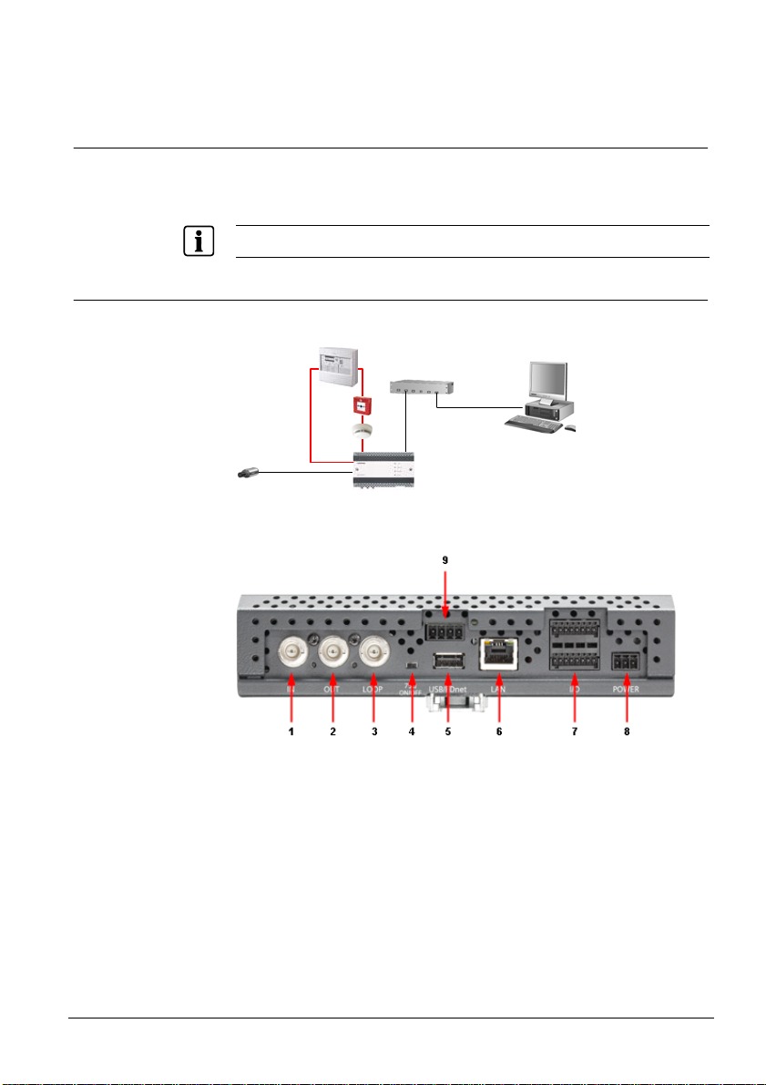
7.2 Anschlüsse
Abb. 2 Anschlüsse Video Fire Controller
1
1 Videoeingang Anschluss von 75 Ohm-BNC-Kabel
2
1 Videoausgang Anschluss von 75 Ohm-BNC-Kabel
3
1 Videoschleife Anschluss von 75 Ohm-BNC-Kabel
4 1 Abschlusswiderstand On: Videosignal nicht durchschleifen
5
USB 2.0 max. 500 mA
6
LAN RJ45 10/100 Mbit Netzwerkanschluss
7
I/O Anschluss
2 Digitale Eingänge Schalten durch Relaiskontakte
2 Digitale Ausgänge Potential getrennt, Open-Collector-Ausgänge, 5 – 24 V,
RS485 Transparenter Datenkanal, PTZ Steuerung
Audio Eingänge/Ausgänge Nicht unterstützt
8
Stromversorgungsanschluss 12 – 24 V DC oder 24 V AC, 15 W
9
FDnet Anschluss FDnet-Melderlinie
10 MC-Link Maintenance and Commissioning Link der FDnet-Schnittstelle
14
Building Technologies
Fire Safety & Security Products 11.2008
Off: Videosignal zu anderem Videoeingang durchschleifen
max. 50 mA
Page 17

Pinbelegung Anschlussblock 7
Gerätebeschreibung
1
Audio Eingang (-)
2
Audio Eingang (+)
3 Audio Ausgang (-) 11 Digitaler Eingang #1 (+)
4
Audio Ausgang (+)
5
Nicht unterstützt
6
Nicht unterstützt
7
Digitaler Ausgang #1 (+)
8 Digitaler Ausgang #1 (-) 16 RS485 (D-)
9
Digitaler Ausgang #2 (+)
10
Digitaler Ausgang #2 (-)
12
Digitaler Eingang #1 (-)
13
Digitaler Eingang #2 (+)
14
Digitaler Eingang #2 (-)
15
RS485 (D+)
Pinbelegung Anschlussblock 8
1
2
3 12 – 24 V DC (+) oder 24 V AC
GND
12 – 24 V DC (-) oder 24 V AC
Pinbelegung Anschlussblock 9
1
FDnet IN LINE -
2 FDnet IN LINE +
3
FDnet OUT LINE -
4 FDnet OUT LINE +
Building Technologies
Fire Safety & Security Products 11.2008
15
Page 18

Gerätebeschreibung
7.3 FDnet spezifische Aspekte
Der Video Fire Controller weißt folgende FDnet spezifische Merkmale auf:
z Kommunikation über FDnet (Melderlinie)
z Eingebauter Linientrenner
Die Kommunikation mit der Zentrale erfolgt über die Melderlinie. Die Konfiguration
erfolgt von der Brandmeldezentrale aus.
Der Video Fire Controller benötigt eine Zusatzspeisung.
Kernfunktionen des Video Fire Controllers
z Aufnahme mit Vor- und Nachlauf von der Brandmeldezentrale aus über das
FDnet auslösen.
z Aufnahme von der Brandmeldezentrale aus über das FDnet direkt starten und
stoppen.
z Sabotage am Video Fire Controller auf der Brandmeldezentrale melden.
Die Meldung wird beispielsweise ausgelöst, wenn das Videosignal der Kamera
unterbrochen wird.
Statuseingänge
Der Video Fire Controller besitzt nur Statuseingänge, diese lösen eine
Zustandsänderung aus, sobald sie aktiviert sind.
Überwachung der Video Funktionalität
Im Fall einer Störung am Video Fire Controller, wird eine Störung zur
Brandmeldezentrale übermittelt. Vergleichen Sie hierzu Kap. 13: Störungsabhilfe.
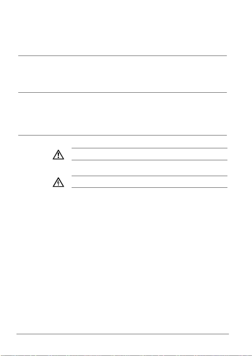
7.3.1 Beispiel zur Anwendung des Video Fire Controllers FDV241
FC20xx
FC20xx
Fire
Fire Brigade
Total:02
Fire
Fire Brigade
Total:02
Alarm
in 04:59 min.
Alarm
in 04:59 min.
+Zone:123 Addr:04 Autom. Fire Alarm
+Zone:123 Addr:04 Autom. Fire Alarm
Entrance Hall / Reception 01
Entrance Hall / Reception 01
+Zone:456 Addr:02 Fire Alarm
+Zone:456 Addr:02 Fire Alarm
ALARM
ALARM
2nd Floor / Room 202 02
2nd Floor / Room 202 02
Intervention
Show
Intervention
Show
Text
Details
Text
Details
User 1
User 1
Optional
Optional
User 2
User 2
Acknowledge
Acknowledge
User 3
User 3
Reset
More Alarms
Reset
More Alarms
User 4
User 4
Remote alarm
Remote alarm
FAULT
FAULT
Alarm delay Of f
Alarm delay Of f
Active
Active
Fault / Off
Fault / Off
ISOLATION
ISOLATION
Premises / Manned
Premises / Manned
Alarm Device
Alarm Device
Active
Active
TEST
TEST
Fault / Off
Fault / Off
User 5
User 5
Control
Control
System
System
Active
Active
On -
On -
User 6
User 6
Fault / Off
Fault / Off
Fault -
Fault -
TM
TM
Sinteso
Sinteso
Brandmelde-
Brandmelde-
zentrale
zentrale
Abb. 3 Anwendungsbeispiel
16
Building Technologies
Fire Safety & Security Products 11.2008
Page 19

Gerätebeschreibung
Der Video Fire Controller ist an eine Kamera angeschlossen und mit dem FDnet
verbunden. Vergleichen Sie hierzu Kap. 9.4: Video Fire Controller FDV241 an
FDnet anschließen. Wenn ein Alarm über ein Peripheriegerät (z. B.
Handfeuermelder) ausgelöst wird, überträgt das FDnet eine Meldung an die
Brandmeldezentrale. Die Brandmeldezentrale sendet daraufhin ebenfalls über das
FDnet eine Meldung an den Video Fire Controller, dem das jeweilige
Peripheriegerät zugeordnet ist. Die aufgenommenen Bilder werden dann mit einer
vordefinierten Vor- und Nachlaufzeit auf dem Compact Flash gespeichert.
Sie können den Video Fire Controller zusätzlich an ein CCTV-System anschließen.
Vergleichen Sie hierzu Kap. 9.5: Video Fire Controller FDV241 an FDnet und
CCTV-System anschließen.
7.3.2 Diagnosestufen im FDnet
Der Video Fire Controller überwacht seine Funktion weitgehend selbst. Aus den
diversen Kontrollmessungen werden folgende Diagnosestufen abgeleitet:
z Normal
z Hinweis beachten
z Tausch empfohlen
z Tausch notwendig
z Störung
Vergleichen Sie hierzu Kap. 13: Störungsabhilfe.
Statusabfrage
Der Video Fire Controller ist mit einem MC-Link (Maintenance and Commissioning
Link) ausgerüstet. Über diesen Link können Sie mit dem Prüfpflücker FDUD29x
folgende Daten abfragen:
z Unzulässige Konfiguration
z Fehlerliste
z Statusregister
Funktionskontrolle
Durch den Selbsttest wird der Video Fire Controller automatisch einer
Funktionskontrolle unterzogen. Trotzdem ist es empfehlenswert, die Geräte in
regelmäßigen Abständen vor Ort zu überprüfen:
z Kontrollieren Sie jährlich die Geräte.
z Ersetzen Sie stark verschmutzte oder beschädigte Geräte.
7.3.3 Notlauf im FDnet
Fällt der Hauptprozessor der Brandmeldezentrale aus, befindet sich diese im
Notlauf-Betrieb. Je nach Zentralentyp kann die Brandmeldezentrale im NotlaufBetrieb die wichtigsten Alarmierungs-Funktionen und Signalisierungs-Funktionen
weiterhin wahrnehmen.
Nicht alle Zentralen unterstützen den Notlauf-Betrieb auf dem FDnet gleich. Bei der
Projektierung sind deshalb zwingend die Informationen im Dokument 'List of
compatibility' (Dok.-Nr. 008331) und der entsprechenden Zentralen-Dokumentation
zu berücksichtigen.
Der Video Fire Controller wird im Notlauf-Betrieb nicht angesteuert.
Building Technologies
Fire Safety & Security Products 11.2008
17
Page 20

Wandmontage
8 Wandmontage
WICHTIG
Überhitzung des Gerätes
Bei Überhitzung wird das Gerät automatisch heruntergefahren.
Î Die LED 1 an der Vorderseite des Gerätes leuchtet rot.
z Prüfen Sie den Mindestabstand von 10 cm zu den Belüftungslöchern am
Gehäusedeckel.
z Prüfen Sie die Umgebungstemperatur. Vergleichen Sie hierzu
Kap. 4: Technische Daten.
Î Bei ausreichender Abkühlung wird das Gerät automatisch hochgefahren.
Gerät an die Hutschiene montieren
1. Schrauben Sie die empfohlene Hutschiene an die Wand.
Vergleichen Sie hierzu Kap. 4: Technische Daten.
VORSICHT
Geräte-/Anlagen- oder Personenschäden durch falsche Montage
Bei falscher Montage besteht die Gefahr, dass das Gerät herunterfällt.
1. Achten Sie bei der Montage darauf, dass das Gerät an der Hutschiene richtig
einrastet.
2. Sichern Sie das Gerät mit Hilfe von Hutschienen-Endhaltern auf beiden
Seiten gegen seitliches Verschieben.
2. Hängen Sie das Gerät von oben in die Hutschiene ein.
3. Klappen Sie das Gerät herunter.
4. Sichern Sie das Gerät mit Hilfe von Hutschienen-Endhaltern auf beiden
Seiten gegen seitliches Verschieben.
Î Das Gerät ist montiert.
Gerät von der Hutschiene abmontieren
1. Ziehen Sie mit dem Schraubenzieher die Lasche in der unteren Mitte des
Gerätes nach unten.
2. Entfernen Sie das Gerät.
Î Das Gerät ist abmontiert.
18
Building Technologies
Fire Safety & Security Products 11.2008
Page 21

9 Inbetriebnahme
Inbetriebnahme
9.1 Gerät öffnen oder schließen
Abb. 4 Video Fire Controller – Schrauben an der Gerätevorderseite
Gerät öffnen
1. Lösen Sie die Schrauben an der Gerätevorderseite.
2. Ziehen Sie den Gehäusedeckel vom Gerät.
Gerät schließen
WICHTIG
Beschädigung des Gerätes
Gefahr einer Beschädigung beim Schließen des Gerätes.
Achten Sie beim Schließen des Gerätes darauf, dass die Lichtleiter
im Gehäusedeckel bzw. die elektronischen Komponenten im Inneren des
Gerätes nicht beschädigt werden.
1. Stecken Sie den Gehäusedeckel auf das Gerät.
2. Ziehen Sie die Schrauben an der Gerätevorderseite fest.
Building Technologies
Fire Safety & Security Products 11.2008
19
Page 22

Inbetriebnahme
9.2 Gerät hoch- oder herunterfahren
Abb. 5 Video Fire Controller – ON/OFF Schalter
1. Öffnen Sie das Gerät. Vergleichen Sie hierzu Kap. 9.1: Gerät öffnen oder
schließen.
2. Halten Sie zum Herunterfahren des Gerätes den ON/OFF Schalter (1) ca.
zwei Sekunden gedrückt.
Î Das Gerät fährt herunter, dies kann einige Sekunden dauern.
Î Die Power LED (2) leuchtet nicht mehr, wenn das Gerät heruntergefahren ist.
3. Drücken Sie den ON/OFF Schalter (1).
Î Das Gerät fährt hoch.
Î Die Power LED (2) leuchtet.
4. Schließen Sie das Gerät. Vergleichen Sie hierzu 9.1: Gerät öffnen oder
schließen.
20
Building Technologies
Fire Safety & Security Products 11.2008
Page 23

Inbetriebnahme
9.3 Compact Flash Karte ein- und ausbauen
Die Compact Flash Karte ermöglicht eine lokale Videoaufzeichnung. Die
Aufzeichnungsdauer hängt vom Video-Stream und der Speicherkapazität ab.
Beispiel
Bei einer Speicherkapazität der Compact Flash Karte von 4 GB, einem Bildformat
von 4CIF bei Standard Qualität und einer Übertragungsgeschwindigkeit von
1 MB/s kann der Video-Stream ca. 2,5 Stunden aufgezeichnet werden.
Aufzeichnungsfehler bei falscher Compact Flash Karte
Bei nicht geeigneter Compact Flash Karte kann es zu Fehlern bei der
Aufzeichnung von Videodaten kommen.
z Achten Sie auf den zulässigen Temperaturbereich von 0 – 70 °C, auf die
minimal notwendige Übertragungsgeschwindigkeit von 1 MB/s und die
minimale Speicherkapazität von 4 GB. Vergleichen Sie hierzu
Kap. 4: Technische Daten.
WICHTIG
Abb. 6 Video Fire Controller Innenansicht
1
ON/OFF An- oder Ausschalter
2 Compact Flash Compact Flash Slot
3
Power Anzeige aus: Gerät ist heruntergefahren
Building Technologies
Fire Safety & Security Products 11.2008
Anzeige an: Gerät ist betriebsbereit
21
Page 24

Inbetriebnahme
Compact Flash Karte einbauen
1. Wählen Sie einen der empfohlenen Compact Flash.
2. Öffnen Sie das Gerät. Vergleichen Sie hierzu Kap. 9.1: Gerät öffnen oder
schließen.
3. Halten Sie den ON/OFF Schalter (1) ca. zwei Sekunden gedrückt.
Î Das Gerät fährt herunter, dies kann einige Sekunden dauern.
Î Die Power LED (3) leuchtet nicht mehr, wenn das Gerät heruntergefahren ist.
4. Stecken Sie den Compact Flash in den Compact Flash Slot (2).
5. Drücken Sie den ON/OFF Schalter (1).
Î Das Gerät fährt hoch.
Î Die Power LED (3) leuchtet.
6. Schließen Sie das Gerät. Vergleichen Sie hierzu Kap. 9.1: Gerät öffnen oder
schließen.
7. Aktivieren Sie die Compact Flash Karte. Informationen hierzu finden Sie im
SISTORE SX/CX Konfigurationshandbuch.
8. Formatieren Sie die Compact Flash Karte. Informationen hierzu finden Sie im
SISTORE SX/CX Konfigurationshandbuch.
Compact Flash Karte ausbauen
1. Deaktivieren Sie die Compact Flash Karte. Informationen hierzu finden Sie im
SISTORE SX/CX Konfigurationshandbuch.
2. Öffnen Sie das Gerät. Vergleichen Sie hierzu Kap. 9.1: Gerät öffnen oder
schließen.
3. Halten Sie den ON/OFF Schalter (1) ca. zwei Sekunden gedrückt.
Î Das Gerät fährt herunter, dies kann einige Sekunden dauern.
Î Die Power LED (3) leuchtet nicht mehr, wenn das Gerät heruntergefahren ist.
4. Ziehen Sie den Compact Flash aus dem Compact Fla sh Slot (2).
5. Drücken Sie den ON/OFF Schalter (1).
Î Das Gerät fährt hoch.
Î Die Power LED (3) leuchtet.
6. Schließen Sie das Gerät. Vergleichen Sie hierzu Kap. 9.1: Gerät öffnen oder
schließen.
22
Building Technologies
Fire Safety & Security Products 11.2008
Page 25

9.4 Video Fire Controller FDV241 an FDnet anschließen (ohne CCTV-Anbindung)
Brandmelder
Inbetriebnahme
FDV241
Brandmeldezentrale
Handfeuermelder
1 Kamera
FDnet
Abb. 7 Video Fire Controller an FDnet ohne CCTV-Anbindung
Abb. 8 Anschlüsse Video Fire Controller
1. Betreiben Sie das Gerät an der Hutschiene. Vergleichen Sie hierzu
Kap. 8: Wandmontage.
2. Schließen Sie eine Kamera an den Videoeingang (1) an.
Falls Durchschleifen erforderlich ist, stellen Sie den Abschlusswiderstand (4)
auf Off und schließen Sie weiterführende Videokabel an der Videoschleife (3)
an.
3. Schließen Sie einen analogen Monitor an das Gerät (2) an.
4. Schließen Sie den Client-PC mit einem gekreuzten Netzwerkkabel (Patch
Kabel) an das Gerät (6) an.
5. Schließen Sie das Spannungsversorgungskabel zuerst an das Gerät (8) und
danach an die Spannungsversorgung an.
6. Schalten Sie den analogen Monitor ein.
Î Es erscheint nach kurzer Zeit die IP-Adresse des Geräts.
7. Schließen Sie den Client-PC an die Spannungsversorgung an.
8. Starten Sie den Client-PC.
9. Stellen Sie die IP-Adresse des Client-PCs ein. Vergleichen Sie hierzu
Kap. 9.7: IP-Adresse des Client-PCs einstellen.
Building Technologies
Fire Safety & Security Products 11.2008
23
Page 26

Inbetriebnahme
10. Installieren und konfigurieren Sie die Software. Vergleichen Sie hierzu
Kap. 10: Software und Kap. 11: Konfiguration.
11. Trennen Sie den analogen Monitor und den Client-PC wieder vom Video Fire
Controller.
12. Schließen Sie den Video Fire Controller an das FDnet (9) an.
13. Konfigurieren Sie das Gerät an der Brandmeldezentrale. Vergleichen Sie
hierzu Kap. 12: FDV241 an der Brandmeldezentrale konfigurieren.
Weitere Informationen zur Konfiguration und Inbetriebnahme der Brandmeldezentrale finden Sie im
Konfigurations- und Benutzerhandbuch der Brandmeldezentrale.
Aufnahmen wiedergeben oder auslagern
Um Aufnahmen beispielsweise wiederzugeben oder auszulagern, muss der
Client-PC wieder mit dem Video Fire Controller verbunden werden:
1. Schließen Sie den Client-PC mit einem gekreuzten Netzwerkkabel (PatchKabel) an den Video Fire Controller (6) an.
2. Geben Sie die Aufnahmen mit der Software SISTORE SX/CX Client wieder
oder lagern Sie diese aus. Informationen hierzu finden Sie im SISTORE
SX/CX Benutzerhandbuch.
3. Trennen Sie den Client-PC wieder vom Video Fire Controller.
24
Building Technologies
Fire Safety & Security Products 11.2008
Page 27
Inbetriebnahme
9.5 Video Fire Controller FDV241 an FDnet und CCTV-System anschließen
Sie können den Video Fire Controller an ein CCTV-System anschließen. Dadurch
werden dieselben CCTV-Funktionen unterstützt, die SISTORE CX1 bietet. Die
Verbindung zum CCTV-System wird via Ethernet hergestellt.
Der Video Fire Controller kann wie alle CCTV-Geräte über IVM bedient werden.
9.5.1 Anlagenbetrieb mit einem Gerät
Brandmeldezentrale
Netzwerk-Switch
FDnet
Client-PC
1 Kamera
Abb. 9 Anlagenbetrieb mit einem Gerät
Abb. 10 Anschlüsse Video Fire Controller
1. Betreiben Sie das Gerät an der Hutschiene. Vergleichen Sie hierzu
Kap. 8: Wandmontage.
2. Schließen Sie eine Kamera an den Videoeingang (1) an.
Falls Durchschleifen erforderlich ist, stellen Sie den Abschlusswiderstand (4)
auf Off und schließen Sie weiterführende Videokabel an der Videoschleife (3)
an.
3. Schließen Sie einen analogen Monitor an das Gerät (2) an.
4. Schließen Sie den Client-PC an den Netzwerk-Switch und diesen mit dem
Netzwerkkabel an das Gerät (6) an.
5. Schließen Sie das Spannungsversorgungskabel zuerst an das Gerät (8) und
danach an die Spannungsversorgung an.
Building Technologies
Fire Safety & Security Products 11.2008
FDV241
25
Page 28

Inbetriebnahme
6. Schalten Sie den analogen Monitor ein.
Î Es erscheint nach kurzer Zeit die IP-Adresse des Geräts.
7. Schließen Sie den Client-PC an die Spannungsversorgung an.
8. Starten Sie den Client-PC.
9. Stellen Sie die IP-Adresse des Client-PCs ein. Vergleichen Sie hierzu
Kap. 9.7: IP-Adresse des Client-PCs einstellen.
10. Installieren und konfigurieren Sie die Software. Vergleichen Sie hierzu
Kap. 10: Software und Kap. 11: Konfiguration.
11. Schließen Sie den Video Fire Controller an das FDnet an (9).
12. Konfigurieren Sie das Gerät an der Brandmeldezentrale. Vergleichen Sie
hierzu Kap. 12: FDV241 an der Brandmeldezentrale konfigurieren.
Weitere Informationen zur Konfiguration und Inbetriebnahme der Brandmeldezentrale finden Sie im
Konfigurations- und Benutzerhandbuch der Brandmeldezentrale.
9.5.2 Anlagenbetrieb mit mehreren Geräten
1 Kamera
FDV241
1 Kamera
FDV241
•
•
•
1 Kamera
FDV241
Abb. 11 Anlagenbetrieb mit mehreren Geräten
Netzwerk-Switch
Client-PC
FDnet
Abb. 12 Anschlüsse Video Fire Controller
26
Building Technologies
Fire Safety & Security Products 11.2008
Page 29

1. Betreiben Sie das Gerät an der Hutschiene. Vergleichen Sie hierzu
Kap. 8: Wandmontage.
2. Schließen Sie die Kamera an den Videoeingang (1) an.
Falls Durchschleifen erforderlich ist, stellen Sie den Abschlusswiderstand (4)
auf Off und schließen Sie weiterführende Videokabel an der Videoschleife (3)
an.
3. Verbinden Sie alle Geräte mit dem Netzwerk-Switch (6).
4. Schließen Sie einen oder mehrere Client-PCs mit dem Netzwerkkabel an den
Netzwerk-Switch an.
5. Schließen Sie einen analogen Monitor an ein Gerät (2) an.
6. Schließen Sie die Spannungsversorgungskabel zuerst an das Gerät (8) und
danach an die Spannungsversorgungen an.
7. Schalten Sie den analogen Monitor ein.
Î Es erscheint nach kurzer Zeit die IP-Adresse des Geräts.
8. Wiederholen Sie die Schritte 5. bis 7. für jedes Gerät.
9. Schließen Sie den Client-PC an die Spannungsversorgung an.
10. Starten Sie den Client-PC.
11. Stellen Sie die IP-Adresse des Client-PCs ein. Vergleichen Sie hierzu
Kap. 9.7: IP-Adresse des Client-PCs einstellen.
12. Installieren und konfigurieren Sie die Software. Vergleichen Sie hierzu
Kap. 10: Software und Kap. 11: Konfiguration.
13. Schließen Sie die Video Fire Controller an das FDnet an (9).
14. Konfigurieren Sie die Geräte an der Brandmeldezentrale. Vergleichen Sie
hierzu Kap. 12: FDV241 an der Brandmeldezentrale konfigurieren.
Weitere Informationen zur Konfiguration und Inbetriebnahme der Brandmeldezentrale finden Sie im
Konfigurations- und Benutzerhandbuch der Brandmeldezentrale.
Inbetriebnahme
Building Technologies
Fire Safety & Security Products 11.2008
27
Page 30

Inbetriebnahme
9.6 Ferritkern anbringen
Die EG-Richtlinie 2004/108/EC „Elektromagnetische Verträglichkeit” wird nur mit einem Ferritkern
erfüllt.
Der Klappferritkern Typ 74271132 der Firma Würth ist im Lieferumfang enthalten.
z Der Abstand zwischen Ferritkern und Gerät darf max. 100 mm betragen.
z Falls das verwendete I/O Kabel nicht in den mitgelieferten Klappferritkern
passt, verwenden Sie einen anderen Ferritkern mit den entsprechenden
elektrischen Eigenschaften.
WICHTIG
1. Schließen Sie das I/O Kabel am I/O Anschluss an.
Abb. 13 Ferritkern um I/O Kabel
1
I/O Anschluss
2
I/O Kabel
3
Ferritkern
2. Bringen Sie um das I/O Kabel den Ferritkern an.
28
Building Technologies
Fire Safety & Security Products 11.2008
Page 31

Inbetriebnahme
9.7 IP-Adresse des Client-PCs einstellen
1. Klicken Sie im Windows Start Menü auf Start > Einstellungen >
Systemsteuerung > Netzwerkverbindungen.
2. Klicken Sie mit der rechten Maustaste auf die ausgewählte
Netzwerkverbindung.
3. Wählen Sie aus dem Kontextmenü den Menüpunkt Eigenschaften.
Î Das Dialogfenster Eigenschaften von Local Area Connection öffnet sich.
4. Wählen Sie ein Internetprotokoll (TCP/IP) aus.
5. Klicken Sie auf die Schaltfläche Eigenschaften.
Î Das Dialogfenster Eigenschaften von Internetprotokoll (TCP/IP) öffnet
sich.
6. Aktivieren Sie das Optionsfeld Folgende IP-Adresse verwenden.
7. Geben Sie IP-Adresse 169.254.xxx.xxx und Subnetzmaske 255.255.0.0 ein.
8. Klicken Sie auf die Schaltfläche OK.
9. Starten Sie Ihren Client-PC neu.
Î Das Gerät ist bereit für die Softwareinstallation. Vergleichen Sie hierzu
Kap. 10: Software.
Building Technologies
Fire Safety & Security Products 11.2008
29
Page 32

Software
10 Software
10.1 Systemvoraussetzungen für den Client-PC
Für den Betrieb der SISTORE Client Software auf den Client-PC empfehlen wir
Ihnen:
Prozessor
Arbeitsspeicher
Freie Festplattenkapazität
Betriebssystem
Grafikkarte
Bildschirmauflösung
Farbtiefe
Intel Pentium 4; mind. 2 GHz
– oder –
AMD Athlon 2800 +; mind. 2 GHz
– oder –
höher
512 MB
5 GB
Windows 2000 oder Windows XP
mit Unterstützung für DirectX 8 oder höher
Getestete Grafikkarten:
– ATI Radeon 9200; 128 MB
– NVIDIA GeForce FX 5200; 256 MB
– Matrox G450
– Matrox G550
min. 1024 x 768 Pixel
16 Bit oder 32 Bit (24 Bit nicht unterstützt)
10.2 Software installieren
1. Legen Sie die mitgelieferte CD in das CD-Laufwerk des Client-PCs ein.
Î Das Installationsprogramm wird automatisch gestartet.
2. Folgen Sie den Anweisungen des Installationsprogammes.
Î Die folgenden Softwareanwendungen werden installiert:
– SISTORE SX/CX Config
– SISTORE SX/CX Client
– SISTORE Player
3. Starten Sie den Client-PC neu, wenn Sie dazu aufgefordert werden.
30
Building Technologies
Fire Safety & Security Products 11.2008
Page 33

Konfiguration
11 Konfiguration
11.1 Software SISTORE SX/CX Config aufrufen
Die Konfiguration des Video Fire Controllers erfolgt über die Software SISTORE SX/CX Config mit
Hilfe der Konfigurationsdatei vfc.xml. Weitere Informationen hierzu finden Sie im SISTORE SX/CX
Konfigurationshandbuch.
1. Wählen Sie im Windows Start Menü Start > Programme > SIEMENS Video
Software Suite > SISTORE SX-CX Config.
Abb. 14 SISTORE SX/CX Startmenü
– oder –
Doppelklicken Sie auf die Desktop-Verknüpfungen SISTORE SX/CX Config.
Abb. 15 SISTORE SX/CX Config Desktop-Verknüpfung
2. Melden Sie sich folgendermaßen an:
Benutzername: admin Kennwort: admin
Î Die Software SISTORE SX/CX Config ist aufgerufen.
11.2 SISTORE SX/CX Konfigurationshandbuch aufrufen
Weitere Anweisungen zur Konfiguration finden Sie im SISTORE SX/CX
Building Technologies
Fire Safety & Security Products 11.2008
Konfigurationshandbuch.
Informationen zur Kamerainstallation und -konfiguration entnehmen Sie der Installationsanleitung und
dem Konfigurationshandbuch der entsprechenden Kamera.
1. Wählen Sie im Windows Start Menü Start > Programme > SIEMENS Video
Software Suite > SISTORE SX-CX Konfigurationshandbuch (vgl. Abb. 14).
Î Das SISTORE SX/CX Konfigurationshandbuch ist aufgerufen.
31
Page 34

FDV241 an der Brandmeldezentrale konfigurieren
12 FDV241 an der Brandmeldezentrale konfigurieren
Parameter Wert IN 1 IN 2 IN 3 IN 4
Eingangstyp
Filterzeit Dauer: ____ s ____ s ____ s 0.5 s
Weitere Informationen zur Konfiguration und Inbetriebnahme der Brandmeldezentrale finden Sie im
Konfigurations- und Benutzerhandbuch der Brandmeldezentrale.
Folgende Einstellungen sind im Video Fire Controller hinterlegt und müssen auf
der Brandmeldezentrale konfiguriert werden:
z Beachten Sie die Kompatibilität. Vergleichen Sie hierzu 'List of compatibility' (Dok.-Nr. 008331).
z Bestimmen Sie den Montageort.
Montageort
Baustein x Ein/Ausgabebaustein FDCC221 (Basistyp: FDCIO222)
Montageart x im Video Fire Controller integriert
Eingang IN 1 überwacht ... Nicht verwendet
Eingang IN 2 überwacht ... Nicht verwendet
Eingang IN 3 überwacht ... Nicht verwendet
Eingang IN 4 überwacht ... Sabotage/Video Signalstörung
Ausgang OUT A steuert ... Video Aufzeichnung mit Vor- und Nachlauf triggern
Ausgang OUT B steuert ... Video Aufzeichnung Start/Stopp
Ausgang OUT C steuert ... Nicht verwendet
Ausgang OUT D steuert ... Nicht verwendet
Eingänge
Gefahreneingang □ □ □ □
Statuseingang □ □ □ x
Abgeschaltet x x x □
Unterbruchsüberwachung □ □ □ x Eingangsbeschaltung
Kurzschluss und Unterbruchsüberwachung □ □ □ □
offen □ □ □ □ Eingang aktiv, wenn Kontakt
geschlossen □ □ □ x
Ausgänge
Parameter Wert OUT A OUT B OUT C OUT D
Überwachung der Steuerung)
Verzögerungszeit (mit
Überwachung der Steuerung)
bzw. dem Ablauf der
Verzögerungszeit (mit
Überwachung der Steuerung)
Verhalten bei einer Störung
32
Building Technologies
Fire Safety & Security Products 11.2008
offen (Öffner, NC) □ □ □ □ Ausgang aktiv, wenn Kontakt
geschlossen (Schließer, NO) x x □ □
ja □ □ □ □ Überwachung der Steuerung
nein x x □ □
permanent □ x □ □ Dauer der Aktivierung (ohne
nur für die Dauer von: x 1 s □ ___ s □ ___ s □ ___ s
Dauer: ____ s ____ s ____ s ____ s
Kontakt bleibt aktiviert □ □ □ □ Verhalten nach der Rückmeldung
Kontakt wird deaktiviert □ □ □ □
Steuerung bleibt gleich wie im Normalbetrieb □ □ □ □
Steuerung wird aktiviert □ □ □ □
Steuerung wird deaktiviert x x □ □
Funktion 'Notlauf-Horn' □ □ □ □
Page 35

Störungsabhilfe
13 Störungsabhilfe
Bei einer Störung, die die Funktion des Video Fire Controllers FDV241
beeinträchtigt, erscheint eine Meldung an der Brandmeldezentrale. Zur Behebung
der Ursache sind zusätzliche Informationen im Video Fire Controller verfügbar.
Diese können beispielsweise durch den Prüfpflücker FDUD29x angezeigt werden
(Details siehe Bedienungsanleitungen Prüfpflücker, Dok.-Nr. 007227 und 009718).
Meldungen Ursache Maßnahmen
Hinweis beachten – –
Tausch empfohlen – –
Tausch notwendig – –
Störung
Die Video-Funktionalität des Video Fire Controllers
ist nicht funktionsbereit.
Die Parametrierung ist ungültig. Überprüfen Sie die Parametrierung.
Es liegt ein Fehler in der Speisung vor. 1. Überprüfen Sie die Melderlinienspannung.
Es liegt ein Software-Fehler (Watchdog-Fehler) vor. Tauschen Sie das Gerät.
Es liegt ein Speicherfehler vor. Tauschen Sie das Gerät.
Es liegt ein Kommunikations-Fehler zwischen
Melder und Zentrale vor.
1. Überprüfen Sie die Video-Funktionalität.
2. Überprüfen Sie die externe
Spannungsversorgung.
2. Tauschen Sie das Gerät.
Beheben Sie die Ursache.
14 Entsorgung
Alle Elektro- und Elektronikgeräte sind getrennt vom allgemeinen Hausmüll über dafür
staatlich vorgesehene Stellen zu entsorgen.
Wenn dieses Symbol eines durchgestrichenen Abfalleimers auf einem Produkt
angebracht ist, unterliegt dieses Produkt der europäischen Richtlinie 2002/96/EC.
Die sachgemäße Entsorgung und getrennte Sammlung von Altgeräten dienen der
Vorbeugung von potenziellen Umwelt- und Gesundheitsschäden. Sie sind eine
Voraussetzung für die Wiederverwendung und das Recycling gebrauchter Elektround Elektronikgeräte. Ausführlichere Informationen zur Entsorgung Ihrer Altgeräte
erhalten Sie bei Ihrer Kommune, Ihrem Müllentsorgungsdienst oder dem
Fachhändler, bei dem Sie das Produkt erworben haben.
Building Technologies
Fire Safety & Security Products 11.2008
33
Page 36

Siemens Schweiz AG
Building Technologies Group
International Headquarters
Fire Safety & Security Products
Gubelstrasse 22
CH-6301 Zug
Tel. +41 41 724 24 24
Fax +41 41 724 35 22
www.sbt.siemens.com
Dokument Nr. A6V10092464 Handbuch FD20
Ausgabe 14.11.2008 Register 3
Liefermöglichkeiten und technische Änderungen vorbehalten.
© 2008 Copyright by
Siemens Schweiz AG
Page 37

FDV241
Video Fire Controller
Startup Manual
SISTORE V3.5
Building Technologies
Fire Safety and Security Products
Page 38

Data and design subject to change without notice. / Supply subject to availability.
© 2008 Copyright by
Siemens Building Technologies
We reserve all rights in this document and in the subject thereof. By acceptance of the document the recipient acknowledges these rights
and undertakes not to publish the document nor the subject thereof in full or in part, nor to make them available to any third party without our
prior express written authorization, nor to use it for any purpose other than for which it was delivered to him.
Page 39

Contents
1 About this document.............................................................................5
2 Safety ................................................................................. ....................6
2.1 Target group............................................................................................6
2.2 Work safety information...........................................................................6
2.2.1 Transport.................................................................................................7
2.2.2 Installation ...............................................................................................7
2.2.3 Setup.......................................................................................................7
2.2.4 Installation ...............................................................................................8
2.3 Meaning of the written warning notices....................................................8
2.4 Meaning of the hazard symbols...............................................................8
3 Directives and standards......................................................................9
4 Technical data .....................................................................................10
4.1 Video Fire Controller FDV241................................................................10
4.2 Transponder FDCC221 (integrated in FDV241) ....................................11
5 Details for ordering........ .....................................................................12
6 Scope of delivery.................................................................................12
7 Description of the device....................................................................13
7.1 LEDs .....................................................................................................13
7.2 Connections ..........................................................................................14
7.3 FDnet-specific aspects ..........................................................................16
7.3.1 Example for the use of the Video Fire Controller FDV241 .....................16
7.3.2 Diagnosis levels in FDnet......................................................................17
7.3.3 Degraded mode in FDnet ......................................................................17
8 Wall mounting......................................................................................18
9 Setup....................................................................................................19
9.1 Opening/closing the device....................................................................19
9.2 Switching the device on or off................................................................20
9.3 Inserting and removing the compact flash card .....................................21
9.4 Connecting the Video Fire Controller FDV241 to the FDnet
9.5 Connecting the Video Fire Controller FDV241 to the FDnet and to
9.5.1 Single-device system.............................................................................25
9.5.2 Multiple-device system..........................................................................26
9.6 Installing the ferrite core ........................................................................28
9.7 Setting the IP address of the client PC..................................................29
10 Software...............................................................................................30
10.1 System requirements for the client PC ..................................................30
10.2 Installing the software............................................................................30
11 Configuration......................... ..............................................................31
11.1 Starting the SISTORE SX/CX Config software ......................................31
11.2 Opening the SISTORE SX/CX Configuration Manual............................31
12 Configuring FDV241 on the fire control panel...................................32
13 Trouble shooting.................................................................................33
14 Disposal ...............................................................................................33
Building Technologies
Fire Safety & Security Products 11.2008
(without connection to the CCTV system)..............................................23
the CCTV system ..................................................................................25
3
Page 40

Page 41

About this document
1 About this document
This Startup Manual contains instructions for installation and setup.
For information on configuration and operation please refer to the Configuration
Manual and the User Manual on the accompanying CD.
Trademarks
All products or company names referred to explicitly in this manual are mentioned
only for purposes of identification or description and may be trademarks or
registered trademarks of their respective owners.
SISTORE is a trademark of Siemens Building Technologies Fire & Security
Products GmbH & Co. oHG.
Microsoft is a registered trademark and Windows a trademark of Microsoft
Corporation.
Training courses
Siemens Building Technologies Fire Safety & Security Products provides training
courses for all products.
Building Technologies
Fire Safety & Security Products 11.2008
5
Page 42

Safety
2 Safety
2.1 Target group
The instructions in this document are designed only for the following target
readers:
Target readers Activity Qualification
Product Manager (PM)
Project Manager
Project Engineer
Installer
Service personnel
Local product management; responsible for the
information exchange between the plant supplying the
equipment and his DU for his product line. Coordination
of the information flow between the parties involved in
a project.
Local project management. Coordination of the
schedules of all groups of people working on a project
as well as of the resources. Procurement of the
technical information required for the implementation of
the project.
Configures the products, devices systems at the DU in
accordance with the national standards and the
customer's requirements. Monitors the serviceability of
the product/device/system and gives the go-ahead for
the commissioning at the place of installation. Performs
troubleshooting and eliminates faults.
Installs the product, device or system components at
the site. Performs a general function check following
installation.
Performs all the service and maintenance work listed in
the product documentation and checks the equipment
to ensure its serviceability.
Has appropriate professional training with
regard to his function and the range of
products and has attended training courses
for product managers.
Has appropriate professional training with
regard to his function, the scope of the
project and the range of products and has
attended the manufacturer’s training
courses for project managers.
Has appropriate professional training with
regard to his function and the
products/devices/systems to be configured
and has attended the manufacturer’s
training courses for project engineers.
Professional training in the field of building
automation or electrical installations.
Has appropriate technical training for the
tasks and the product.
2.2 Work safety information
z Read the general safety precautions before operating the device.
z Keep this document for reference.
z Always pass this document on together with the product.
z Any national or local safety standards or laws that apply to the development,
design, installation, operation or disposal of a product must be adhered to in
addition to the instructions in the product documentation.
z Use only auxiliary equipment (e.g. ladder) that is appropriate for the purpose.
z If devices from third-party firms are to be operated, the responsible person must
be present.
Radio interference with other devices in the environment
z This is a Class A device. This equipment may cause radio interference in a
residential installation. In this case the user is encouraged to perform
appropriate measures to correct the interference.
6
Building Technologies
Fire Safety & Security Products 11.2008
Page 43

Safety
Liability claim
z Do not connect the device if it is damaged or any parts are missing.
z Do not make any changes or modifications to the device unless they are
expressly mentioned in this manual and have been approved by the
manufacturer.
z Use only spare parts and accessories approved by the manufacturer.
z Work on electrical systems should only be performed by trained personnel under
the supervision of a certified electrician in accordance with the appropriate
regulations.
2.2.1 Transport
2.2.2 Installation
2.2.3 Setup
Damage during transport
z Keep the packaging material for future transportation.
z Do not expose the device to mechanical vibrations or shocks.
Cable damage due to mec hanical load
z Do not apply tensile stress to the cable.
z Make sure that cables are not under stress, kinked or damaged.
Damage to equipment due to fire controls
z When fire controls are activated for test purposes, any damage to system parts
must be ruled out.
z Fire control installations must only be activated after the test has been
completed and the system has been definitely handed over to the customer.
Damage due to unsuitable mounting location
z Observe the environmental requirements recommended by the manufacturer.
z Do not operate the device close to sources of powerful electromagnetic
radiation.
z Protect the device against moisture.
z Do not operate the device in excessively dusty places.
z Do not expose the device to mechanical vibrations or shocks.
Damage to the device due to lack of ventilation
z Do not block or cover the ventilation openings of the device.
Dangerous situation due to false alarm
z Make sure to notify all relevant parties and authorities providing assistance
before testing the system.
z To avoid panic, always inform all those present before testing any alarm
devices.
Building Technologies
Fire Safety & Security Products 11.2008
7
Page 44

Safety
Damage to the device due to overvoltage
z Connect the device only to power sources with the specified voltage. Voltage
supply requirements can be found on the type label.
2.2.4 Installation
Data loss after software update
z Make sure to backup all data before updating the software.
2.3 Meaning of the written warning notices
The severity of a hazard is indicated by the following written warning notices.
IMPORTANT
CAUTION
Malfunctioning may result
There is a risk of minor injuries or damage to property.
2.4 Meaning of the hazard symbols
Caution - Dangerous area!
Caution: Dangerous electrical voltage!
8
Building Technologies
Fire Safety & Security Products 11.2008
Page 45

Directives and standards
3 Directives and standards
Compliance with the European Directive 2004/108/EC „Electromagnetic Compatibility” is achieved
only if the device is equipped with a ferrite core (see Section 9.6: Installing the ferrite core).
This product complies with the requirements of the following European directives.
The EU declaration of conformity is available from:
Siemens Building Technologies
Fire & Security Products GmbH & Co. oHG
76181 Karlsruhe
Germany
European Directive 2004/108/EC „Electromagnetic Compatibility”
Compliance with the European Directive 2004/108/EC has been proven by testing
according to the following standards:
Emitted interference: EN 61000-6-4
Interference resistance: EN 50130-4
EN 55022 Class A
European Directive 89/106/EG „Construction Products“
Compliance with the European Directive 89/106/EEC has been proven by testing
according to the following standard:
Short-circuit isolators: EN 54-17
Input/
output devices:
EN 54-18
Building Technologies
Fire Safety & Security Products 11.2008
9
Page 46

Technical data
4 Technical data
4.1 Video Fire Controller FDV241
Application Encoding and decoding of video signals, transmission, recording and evaluation
Operating temperature -10 to +50 °C
Relative humidity 20 – 80 % without condensation
Weight 0.95 kg
Power supply 12 – 24 V DC or 24 V AC, max. 1.25 A
The power supply for the device must comply with SELV (Safety Extra Low
Voltage) and LPS (Limited Power Source) requirements and with the EN 60950-1
standard.
Power consumption Max. 15 W
Inputs and outputs Design: plug-type connection
Cross-section: 0.2 – 1.5 mm
Compact flash slot CF-type I: 42.8 x 36.4 x 3.3 mm
Compact flash card Permissible temperature range: 0 – 70 °C
Min. transmission speed: 1 MB/s r/w
Min. storage capacity: 4 GB
Battery Varta 6032
Top-hat rail Mounting rail to DIN EN 50022
35 x 7.5 mm; 2.3 mm thick
– OR –
35 x 15 mm; 2.3 mm thick
Dimension (H x W x D) 192 x 110 x 44 mm
Standards
Protection rating EN 60529
IP20
EMC EN 61000-6-4
EN 50130-4
QA standards Siemens Standard SN 36350
ISO9001
ISO9004
CE Conformity Marking Yes
2
10
Building Technologies
Fire Safety & Security Products 11.2008
Page 47

Technical data
4.2 Connection to transponder FDCC221 (integrated in FDV241)
Connections Design: plug-type connection
Cross-section: 0.2 – 1.5 mm
Operating voltage 12 – 33 V DC
Operating current (closed circuit) 0.6 – 0.75 mA
Operating temperature -10 to +55 °C,
Relative humidity ≥ 95 % rel. (at T = 25 ±3 °C)
93 % rel. (at T = 40 ±2 °C)
temporary condensation permissible
Maximum current connection factor 3
Quiescent current connection factor 3
Address connection factor 1
Separator connection factor 1
Protocol FDnet
Compatibility For details see doc. no. 008331 'List of compatibility'
External alarm indicator
Connector for external alarm indicator None
Standards
CPD EN 54-17
EN 54-18
VdS approvals G208063
2
Building Technologies
Fire Safety & Security Products 11.2008
11
Page 48

Details for ordering
5 Details for ordering
Type Order no. Designation Weight
FDV241 S54335-F1-A1 Video Fire Controller 0.95 kg
Accessories, not included in the delivery!
Recommended accessories
Type Order no. Designation Weight
CCBC1345-LP 2GF1183-8GA 1/3" DSP colour DIP switch camera 480 TVL, PAL,
12 V DC / 24 V AC
CLVD1314/3.5-8 2GF1667-8AJ 3.5 – 8 mm F1.4 1/3" CS 0.0766 kg
CAB1420 2GF1710-8BD Universal camera mount 140 mm 0.25 kg
CFVC1317-LP S54561-C61-A1 1/3" CCD 3,7 – 12 mm Colour Varifocal Dome
540 TVL, PAL, 12 V DC / 24 V AC, 3,5 W
0.45 kg
0.29 kg
6 Scope of delivery
z Video Fire Controller
z Software CD with configuration manual and user manual
z Startup manual
z Voltage supply connector
z I/O connector
z FDnet connector
z Snap-on ferrite core type 74271132, manufacturer: Würth
12
Building Technologies
Fire Safety & Security Products 11.2008
Page 49

7 Description of the device
Description of the device
7.1 LEDs
Displays on the front side
Fig. 1 Displays on the Video Fire Controller
1 Video
2
FDnet activity
3
Storage
No indicator: No camera connected
Red: Alarm, initializing, overheated
Green: Receiving camera signal
Orange: Live image or recording
Blinking red,
green or orange:
No indicator: FDnet is not connected
Lit green: FDnet is connected and working properly
Blinking green: Locating
No indicator: No video recording on compact flash or
Blinking green: Memory access to compact flash, e.g. while recording is
No indicator: Device is switched off 4 Power
Lit green: Device is ready for operation or starting up or shutting
Device starting up or shutting down
No compact flash present
in progress
down
1 Blinking green: Data transmission
2
No indicator: No physical connection
Lit yellow: Physical connection exists
See Section 7.2: Connections.
Displays on LAN connection
Building Technologies
Fire Safety & Security Products 11.2008
13
Page 50

Description of the device
7.2 Connections
Fig. 2 Connections on the Video Fire Controller
1 1 video input Connection for 75 Ω BNC cable
2 1 video output Connection for 75 Ω BNC cable
3
1 video loop Connection for 75 Ω BNC cable
4
1 terminating resistor On: no video signal loop-through
5
USB 2.0 max. 500 mA
6
LAN RJ45 10/100 Mbit network connection
I/O connector
7
2 digital inputs Switch via relay contacts
2 digital outputs Electrically isolated, Open-Collector outputs, 5 – 24 V,
RS485 Transparent data channel, PTZ control
Audio inputs/outputs Not supported
8 Power supply 12 – 24 V DC or 24 V AC, 15 W
9
FDnet Connection for FDnet detector line
10
MC link Maintenance and commissioning link for the FDnet interface
14
Building Technologies
Fire Safety & Security Products 11.2008
Off: video signal loops through to another video input
max. 50 mA
Page 51

Pin assignment terminal block 7
Description of the device
1
Audio input (-)
2
Audio input (+)
3 Audio output (-) 11 Digital input #1 (+)
4
Audio output (+)
5
Not supported
6
Not supported
7
Digital output #1 (+)
8 Digital output #1 (-) 16 RS485 (D-)
9
Digital output #2 (+)
10
Digital output #2 (-)
12
Digital input #1 (-)
13
Digital input #2 (+)
14
Digital input #2 (-)
15
RS485 (D+)
Pin assignment terminal block 8
1
2
3 12 – 24 V DC (+) or 24 V AC
GND
12 – 24 V DC (-) or 24 V AC
Pin assignment terminal block 9
1
FDnet IN LINE -
2 FDnet IN LINE +
3
FDnet OUT LINE -
4 FDnet OUT LINE +
Building Technologies
Fire Safety & Security Products 11.2008
15
Page 52

Description of the device
7.3 FDnet-specific aspects
The Video Fire Controller offers the following FDnet-specific features:
z Communication via FDnet (detector line)
z Integrated line separator
Communication with the fire control panel takes place over the detector line. The
Video Fire Controller is configured from the fire control panel.
The Video Fire Controller requires auxiliary power supply.
Basic functions of the Video Fire Controller
z Trigger recordings with pre-event and post-event recording from the fire control
panel via the FDnet.
z Start/stop recording directly from the fire control panel via the FDnet.
z Report tampering of the Video Fire Controller to the fire control panel.
The alarm message is generated, for instance, when the video signal of the
camera is interrupted.
Status inputs
The inputs of the Video Fire Controller are status input, which will trigger a change
of state as soon as they are activated.
Monitoring of the video functionality
In case of a malfunction of the Video Fire Controller, an error message will be sent
to the fire control panel. See Section 13: Trouble shooting.
7.3.1 Example for the use of the Video Fire Controller FDV241
FC20xx
FC20xx
Fire
Fire Brigade
Total:02
Fire
Fire Brigade
Total:02
Alarm
in 04:59 min.
Alarm
in 04:59 min.
+Zone:123 Addr:04 Autom. Fire Alarm
+Zone:123 Addr:04 Autom. Fire Alarm
Entrance Hall / Reception 01
Entrance Hall / Reception 01
+Zone: 456 Addr: 02 Fire Alarm
+Zone: 456 Addr: 02 Fire Alarm
ALARM
ALARM
2nd Floor / Room 202 02
2nd Floor / Room 202 02
Intervention
Show
Intervention
Show
Text
Details
Text
Details
User 1
User 1
Optional
User 2
Optional
User 2
Acknowledge
Acknowledge
User 3
User 3
Reset
More Alarms
Reset
More Alarms
User 4
User 4
Remote alarm
Remote alarm
FAULT
FAULT
Alarm delay O ff
Alarm delay O ff
Active
Active
Fault / Off
Fault / Off
Premises / Manned
Premises / Manned
ISOLATION
ISOLATION
Alarm Device
Alarm Device
Active
Active
TEST
TEST
Fault / Off
Fault / Off
User 5
User 5
Control
Control
System
System
Active
Active
On -
On -
User 6
User 6
Fault / Off
Fault / Off
Fault -
Fault -
TM
TM
Sinteso
Sinteso
Fire control
panel
Fig. 3 Example of use
The Video Fire Controller is connected to a camera and to the FDnet. See Section
9.4: Connecting the Video Fire Controller FDV241 to the FDnet. When an alarm is
triggered via a peripheral device (e.g. manual call point), a message is sent to the
16
Building Technologies
Fire Safety & Security Products 11.2008
Page 53

Description of the device
fire control panel via the FDnet. The fire control panel then sends a message via
the FDnet to the Video Fire Controller assigned to the particular peripheral device.
The images captured by the camera are then stored on the compact flash with a
predefined pre-event and post-event recording time.
The Video Fire Controller can be additionally connected to a CCTV system. See
Section 9.5: Connecting the Video Fire Controller FDV241 to the FDnet and to the
CCTV system.
7.3.2 Diagnosis levels in FDnet
The Video Fire Controller is largely self-monitoring. The following diagnosis levels
are taken from the various check measurements:
z Normal
z Observe information
z Exchange recommended
z Exchange required
z Fault
See Section 13: Trouble shooting.
Status request
The Video Fire Controller is equipped with an MC-link (maintenance and
commissioning link). With the detector exchanger and tester FDUD29x, the
following data can be displayed:
z Inadmissible configuration
z Error list
z Status register
Functional check
The self-test function ensures that the Video Fire Controller is checked
automatically. It is nevertheless advisable to check the devices at regular intervals
on site:
z Check the devices annually.
z Replace all devices that are extremely soiled or damaged.
7.3.3 Degraded mode in FDnet
When the main processor of the fire control panel fails, the control panel is in
degraded mode. Depending on the control panel type, the fire control panel can
continue to perform the most important alarming and signalling functions in
degraded mode.
The degraded operation on the FDnet is not equally supported by all control
panels. During project planning, the information in the document 'List of
compatibility' (doc. no. 008331) and the control panel documentation in account is
mandatory.
The Video Fire Controller is not activated when the system is running in degrade
mode.
Building Technologies
Fire Safety & Security Products 11.2008
17
Page 54

Wall mounting
8 Wall mounting
IMPORTANT
Mounting the device to the top-hat rail
1. Screw the recommended top-hat rail to the wall.
See Section 4: Technical data.
CAUTION
2. Hang the device in the top-hat rail from above.
3. Flip the device down.
4. Secure the device against lateral displacement using rail stoppers on both
sides.
Î The device is now mounted.
Removing the device from the top-hat rail
1. Use a screwdriver to pull the tab in the middle of the bottom of the device
down.
2. Remove the device.
Î The device is now dismounted.
Overheating of the device
In case of overheating the device will shut down automatically.
Î LED 1 on the front of the device will be lit red.
z Check to ensure there is a minimum clearance of 10 cm to the ventilation
holes on the housing cover.
z Measure the ambient temperature. See Section 4: Technical data.
Î When the device has cooled down sufficiently, it will boot up automatically.
Risk of bodily injury or damage to the device/system due to incorrect
installation
If the device is not mounted correctly there is a risk that it will fall down.
1. Make sure that the device properly engages into the top-hat rail.
2. Secure the device against lateral displacement using rail stoppers on both
sides.
18
Building Technologies
Fire Safety & Security Products 11.2008
Page 55

9 Setup
Setup
9.1 Opening/closing the device
Fig. 4 Video Fire Controller – Screws on the front side of the device
Opening the device
1. Remove the screws on the front side of the device.
2. Remove the housing cover.
Closing the device
IMPORTANT
Damage to the device
Risk of damage when closing the device.
When closing the device make sure not to damage the extension pipes in the
housing cover or the electronic components inside the device.
1. Place the housing cover on the device.
2. Tighten the screws on the front side of the device.
Building Technologies
Fire Safety & Security Products 11.2008
19
Page 56

Setup
9.2 Switching the device on or off
Fig. 5 Video Fire Controller – ON/OFF switch
1. Open the device. See Section 9.1: Opening/closing the device.
2. To shut down the device, press the ON/OFF switch (1) for approx. 2 seconds.
Î The device switches off, which can take several seconds.
Î Once the device is switched off, the Power LED (2) will no longer be lit.
3. Press the ON/OFF switch (1).
Î The device boots up.
Î The Power LED (2) lights up.
4. Close the device. See Section 9.1: Opening/closing the device.
20
Building Technologies
Fire Safety & Security Products 11.2008
Page 57

Setup
9.3 Inserting and removing the compact flash card
The compact flash card enables local video recording. The length of the recording
depends on the video stream and on the storage capacity.
Example
If the compact flash card has a storage capacity of 4 GB, an image format of 4CIF
at standard quality and a transfer rate of 1 MB/s, then the video stream can be
recorded for approx. 2.5 hours.
IMPORTANT
Recording errors when using the wrong Compact Flash card
Using an improper Compact Flash card can cause errors upon recording video
data.
z Make sure the card meets the requirements for the permissible temperature
range of 0 – 70 °C, the minimum required transfer rate of 1 MB/s and the
minimum storage capacity of 4 GB. See Section 4: Technical data.
Fig. 6 Video Fire Controller - Interior view
1
ON/OFF On / off switch
2
Compact Flash Compact flash slot
3 Power No indicator: Device is switched off
Building Technologies
Fire Safety & Security Products 11.2008
Display on: Device is ready for operation
21
Page 58

Setup
Inserting the compact flash card
1. Select a recommended compact flash.
2. Open the device. See Section 9.1: Opening/closing the device.
3. Press and hold the ON/OFF switch (1) for approx. 2 seconds.
Î The device switches off, which can take several seconds.
Î Once the device is switched off, the Power LED (3) will no longer be lit.
4. Insert the compact flash card in the Compact Flash Slot (2).
5. Press the ON/OFF switch (1).
Î The device boots up.
Î The Power LED (3) lights up.
6. Close the device. See Section 9.1: Opening/closing the device.
7. Activate the compact flash card. Further information on this can be found in
the SISTORE SX/CX Configuration Manual.
8. Format the compact flash card. Further information on this can be found in the
SISTORE SX/CX Configuration Manual.
Removing the compact flash card
1. Deactivate the compact flash card. Further information on this can be found in
the SISTORE SX/CX Configuration Manual.
2. Open the device. See Section 9.1: Opening/closing the device.
3. Press and hold the ON/OFF switch (1) for approx. 2 seconds.
Î The device switches off, which can take several seconds.
Î Once the device is switched off, the Power LED (3) will no longer be lit.
4. Remove the compact flash card from the Comp a ct Flash slot (2).
5. Press the ON/OFF switch (1).
Î The device boots up.
Î The Power LED (3) lights up.
6. Close the device. See Section 9.1: Opening/closing the device.
22
Building Technologies
Fire Safety & Security Products 11.2008
Page 59

9.4 Connecting the Video Fire Controller FDV241 to the FDnet
(without connection to the CCTV system)
Fire detectors
Setup
Fire panel
FDV241
Manual call point
1 camera
FDnet
Fig. 7 Video Fire Controller connected to the FDnet, without connection to the
CCTV system
Fig. 8 Connections on the Video Fire Controller
1. Operate the device on the top-hat rail. See Section 8: Wall mounting.
2. Connect a camera to the video input (1).
If loop-through is necessary, set the terminating resistor (4) to Off and connect
the video cable extension to the video loop (3).
3. Connect an analogue monitor to the device (2).
4. Connect the client PC to the device (6) using a patch cable.
5. Connect the power supply cable to the device (8) first and then to the power
source.
6. Switch on the analogue monitor.
Î After a short wait, the IP address of the device will appear on the screen.
7. Connect the client PC to the power supply.
8. Start the client PC.
9. Set the IP address of the client PC. See Section 9.7: Setting the IP address of
the client PC.
10. Install the software and configure it. See Section 10: Software and
Section 11: Configuration.
11. Disconnect the analog monitor and the client PC from the Video Fire
Controller.
12. Connect the Video Fire Controller to the FDnet (9).
Building Technologies
Fire Safety & Security Products 11.2008
23
Page 60

Setup
13. Configure the device on the fire control panel. See Section 12: Configuring
FDV241 on the fire control panel.
More detailed information on the configuration and setup of the fire control panel can be found in the
configuration and user manual for the fire control panel.
Replaying or archiving recordings
If you want to play or export recorded sequences, the client PC must be connected
to the Video Fire Controller again:
1. Connect the client PC to the Video Fire Controller (6) using a patch cable.
2. Play the recorded sequences using the SISTORE SX/CX Client software or
archive them. Further information on this can be found in the SISTORE
SX/CX user manual.
3. Disconnect the client PC from the Video Fire Controller.
24
Building Technologies
Fire Safety & Security Products 11.2008
Page 61

Setup
9.5 Connecting the Video Fire Controller FDV241 to the FDnet and
to the CCTV system
The Video Fire Controller can be connected to a CCTV system. It then supports
the same CCTV functions as SISTORE CX1. The connection to the CCTV system
is set up via Ethernet.
The Video Fire Controller can be operated using IVM just like the CCTV equipment.
9.5.1 Single-device system
Fire panel
Network switch
FDnet
Client PC
1 camera
Fig. 9 Single-device system
Fig. 10 Connections on the Video Fire Controller
1. Operate the device on the top-hat rail. See Section 8: Wall mounting.
2. Connect a camera to the video input (1).
If loop-through is necessary, set the terminating resistor (4) to Off and connect
the video cable extension to the video loop (3).
3. Connect an analogue monitor to the device (2).
4. Connect the client PC to the network switch, and use the network cable
provided to connect the switch to the device (6).
5. Connect the power supply cable to the device (8) first and then to the power
source.
6. Switch on the analogue monitor.
Î After a short wait, the IP address of the device will appear on the screen.
Building Technologies
Fire Safety & Security Products 11.2008
FDV241
25
Page 62

Setup
7. Connect the client PC to the power supply.
8. Start the client PC.
9. Set the IP address of the client PC. See Section 9.7: Setting the IP address of
the client PC.
10. Install the software and configure it. See Section 10: Software and
Section 11: Configuration.
11. Connect the Video Fire Controller to the FDnet (9).
12. Configure the device on the fire control panel. See Section 12: Configuring
FDV241 on the fire control panel.
More detailed information on the configuration and setup of the fire control panel can be found in the
configuration and user manual for the fire control panel.
9.5.2 Multiple-device system
1 c amera
FDV241
1 c amera
FDV241
1 camera
FDV241
Fig. 11 Multiple-device system
Fig. 12 Connections on the Video Fire Controller
Network switch
Client PC
•
•
•
FDnet
26
Building Technologies
Fire Safety & Security Products 11.2008
Page 63

1. Operate the device on the top-hat rail. See Section 8: Wall mounting.
2. Connect the camera to the video input (1).
If loop-through is necessary, set the terminating resistor (4) to Off and connect
the video cable extension to the video loop (3).
3. Connect all devices to the network switch (6).
4. Connect one or more client PCs to the network switch using the network cable
provided.
5. Connect an analog monitor to one of the devices (2).
6. Connect the power supply cable to the device (8) first and then to the power
source.
7. Switch on the analogue monitor.
Î After a short wait, the IP address of the device will appear on the screen.
8. Repeat steps 5 to 7 for each device.
9. Connect the client PC to the power supply.
10. Start the client PC.
11. Set the IP address of the client PC. See Section 9.7: Setting the IP address of
the client PC.
12. Install the software and configure it. See Section 10: Software and
Section 11: Configuration.
13. Connect the Video Fire Controllers to the FDnet (9).
14. Configure the devices on the fire control panel. See Section 12: Configuring
FDV241 on the fire control panel.
More detailed information on the configuration and setup of the fire control panel can be found in the
configuration and user manual for the fire control panel.
Setup
Building Technologies
Fire Safety & Security Products 11.2008
27
Page 64

Setup
9.6 Installing the ferrite core
Compliance with the European Directive 2004/108/EC „Electromagnetic Compatibility” will be
achieved only if the device is equipped with a a ferrite core.
The snap-on ferrite core type 74271132 (manufacturer: Würth) is included in the
delivery.
IMPORTANT
z The distance between the ferrite core and the device must not exceed 100
mm.
z In case the I/O cable used should not fit into the snap-on ferrite core supplied,
another ferrite core with the same electrical properties has to be used.
1. Connect the I/O cable to the I/O port.
Fig. 13 Ferrite core snapped onto the I/O cable
1
I/O connector
2
I/O cable
3
Ferrite core
2. Snap the ferrite core onto the I/O cable.
28
Building Technologies
Fire Safety & Security Products 11.2008
Page 65

Setup
9.7 Setting the IP address of the client PC
1. Select Start > Settings > Control Panel > Network Connections
in the Windows Start menu.
2. Right-click on the selected network connection.
3. Select Properties in the context menu.
Î The Local Area Connection Properties dialog box appears.
4. Select an Inte rnet protocol (TCP/IP).
5. Click on Properties.
Î The Internet Protocol (TCP/IP) Properties dialog box appears.
6. Activate the option Use the following IP address.
7. Enter 169.254.xxx.xxx for the IP address and 255.255.0.0 for the subnet
mask.
8. Click OK.
9. Restart your client PC.
Î The device is now ready for software installation. See Section 10: Software.
Building Technologies
Fire Safety & Security Products 11.2008
29
Page 66

Software
10 Software
10.1 System requirements for the client PC
The PC on which the SISTORE Client Software is installed should meet the
following requirements:
Processor
RAM 512 MB
Available hard drive
capacity
Operating system Windows 2000 or Windows XP
Graphics card
Screen resolution
Colour depth
Intel Pentium 4; 2 GHz or faster
– OR –
AMD Athlon 2800+; 2 GHz or faster
– OR –
higher
5 GB
With support for DirectX 8 (or later version)
Graphics cards tested:
– ATI Radeon 9200, 128 MB
– NVIDIA GeForce FX 5200, 256 MB
– Matrox G450
– Matrox G550
Min. 1024 x 768 pixels
16 bit or 32 bit (24 bit not supported)
10.2 Installing the software
1. Place the CD in the CD drive of the client PC.
Î The installation program is started automatically.
2. Follow the instructions of the installation program.
Î The following software applications will be installed:
– SISTORE SX/CX Config
– SISTORE SX/CX Client
– SISTORE Player
3. Restart the client PC when you are prompted to do so.
30
Building Technologies
Fire Safety & Security Products 11.2008
Page 67

Configuration
11 Configuration
11.1 Starting the SISTORE SX/CX Config softw are
The Video Fire Controller is configured in SISTORE SX/CX Config using the configuration file vfc.xml.
Further information on this can be found in the SISTORE SX/CX configuration manual.
1. Select Start > Programs > SIEMENS Video Software Suite > SISTORE SXCX Config in the Windows start menu.
Fig. 14 SISTORE SX/CX start menu
– OR –
Double click on the desktop shortcut SISTORE SX-CX Config.
Fig. 15 SISTORE SX/CX Config desktop shortcut
2. Log on to the server using the following user name and password.
User name: admin Password: admin
Î The SISTORE SX/CX Config software has been started.
11.2 Opening the SISTORE SX/CX Configuration Manual
For further information on configuration please refer to the SISTORE SX/CX
Building Technologies
Fire Safety & Security Products 11.2008
Configuration Manual.
For information on the installation and configuration of the cameras please refer to the installation
guide and the configuration manual for the appropriate camera.
1. Select Start > Programs > SIEMENS Video Software Suite > SISTORE SXCX Configuration Manual in the Windows start menu (see Fig. 14)
Î The SISTORE SX/CX Configuration Manual is opened.
31
Page 68

Configuring FDV241 on the fire control panel
12 Configuring FDV241 on the fire control panel
Parameter Value IN 1 IN 2 IN 3 IN 4
Input type
Filter time Duration: ____ s ____ s ____ s 0.5 s
More detailed information on the configuration and setup of the fire control panel can be found in the
configuration and user manual for the fire control panel.
The following settings are stored on the Video Fire Controller and have to be
configured on the fire control panel:
z Make sure the devices are compatible. Please refer to the 'List of compatibility' (Doc. No. 008331).
z Select a mounting location.
Mounting location
Module x input/output module FDCC221 (basic model: FDCIO222)
Type of installation x integrated in the Video Fire Controller
Input IN 1 monitored ... Not used
Input IN 2 monitored ... Not used
Input IN 3 monitored ... Not used
Input IN 4 monitored ... Tampering/loss of video signal
Output OUT A controls ... Trigger video recording with pre-event recording and post-event
Output OUT B controls ... Start/stop video recording
Output OUT C controls ... Not used
Output OUT D controls ... Not used
times
Inputs
Danger input □ □ □ □
Status input □ □ □ x
Switched off x x x □
Open-line monitoring □ □ □ x Input circuit
Short-circuit and open-line monitoring □ □ □ □
open □ □ □ □ Input active when contact is
closed □ □ □ x
Outputs
Parameter Value OUT A OUT B OUT C OUT D
control monitoring)
Delay period (with control
monitoring)
ment or expiry of the delay period
(with control monitoring)
Behaviour in case of fault
32
Building Technologies
Fire Safety & Security Products 11.2008
open (normally closed/NC) □ □ □ □ Output active when contact is
closed (normally open/NO) x x □ □
Yes □ □ □ □ Control monitoring
No x x □ □
Permanent □ x □ □ Duration of activation (without
Only for a period of: x 1 s □ ___ s □ ___ s □ ___ s
Duration: ____ s ____ s ____ s ____ s
Contact remains active □ □ □ □ Behaviour after acknowledge-
Contact is deactivated □ □ □ □
Control remains the same as in normal operation □ □ □ □
Control is activated □ □ □ □
Control is deactivated x x □ □
"Degraded-mode horn" function □ □ □ □
Page 69

Trouble shooting
13 Trouble shooting
When an error occurs which affects the proper function of the Video Fire
Controllers FDV241, a message is generated on the fire control panel. To remedy
the cause, additional information is available in the Video Fire Controller. This
information may be displayed for instance by the detector exchanger and tester
FDUD29x (for details see instruction manual for detector exchanger and tester,
doc. nos. 007227 and 009718).
Messages Cause Measures
Observe information – –
Exchange recommended – –
Exchange required – –
Error
The video functionality of the Video Fire Controller
is not available.
Invalid configuration. Check the configuration.
There is a power supply error. 1. Check the detector line voltage.
There is a software error (watchdog error). Exchange the device.
There is a storage error. Exchange the device.
There is a communication error between a detector
and the fire control panel.
1. Check the video functionality.
2. Check the external power source.
2. Exchange the device.
Eliminate the cause of the fault.
14 Disposal
All electrical and electronic products should be disposed of separately from the
municipal waste stream via designated collection facilities appointed by the
government or the local authorities.
This crossed-out wheeled bin symbol on the product means the product is covered by
the European Directive 2002/96/EC.
The correct disposal and separate collection of your old appliance will help prevent
potential negative consequences for the environment and human health. It is a
precondition for reuse and recycling of used electrical and electronic equipment. For
more detailed information about disposal of your old appliance, please contact your
city office, waste disposal service or the shop where you purchased the product.
Building Technologies
Fire Safety & Security Products 11.2008
33
Page 70

Siemens Schweiz AG
Building Technologies Group
International Headquarters
Fire Safety & Security Products
Gubelstrasse 22
CH-6301 Zug
Tel. +41 41 724 24 24
Fax +41 41 724 35 22
www.sbt.siemens.com
Document No. A6V10092464 Manual FD20
Edition 14.11.2008 Section 3
Data and design subject to change without notice.
© 2008 Copyright by
Siemens Schweiz AG
Supply subject to availability.
Page 71

FDV241
Video Fire Controller
Manual de inicio
SISTORE V3.5
Building Technologies
Fire Safety and Security Products
Page 72

Datos y diseño sujetos a modificaciones sin previo aviso. / Suministro sujeto a disponibilidad.
© 2008 Copyright de
Siemens Building Technologies
El fabricante se reserva todos los derechos sobre este documento y el asunto en él tratado. Al aceptar este documento, el receptor
reconoce estos derechos y se compromete a no publicar el documento ni el asunto en él tratado ya sea total o parcialmente, y a no ponerlo
a disposición de terceros sin la previa autorización por escrito del fabricante ni a usarlo para otros fines que no sean los establecidos al
entregarle el documento.
Page 73

Contenido
1 Acerca de este documento...................................................................5
2 Seguridad...............................................................................................6
2.1 Grupo objetivo.........................................................................................6
2.2 Información sobre seguridad laboral........................................................6
2.2.1 Transporte...............................................................................................7
2.2.2 Montaje ...................................................................................................7
2.2.3 Preparación.............................................................................................7
2.2.4 Instalación ...............................................................................................8
2.3 Significado de los avisos escritos............................................................8
2.4 Significado de los símbolos de peligro.....................................................8
3 Directivas y normas..................... ........ ....... ............... ....... ........ ....... .....9
4 Datos técnicos...................................... ...............................................10
4.1 Video Fire Controller FDV241................................................................10
4.2 Conexión a transpondedor FDCC221 (integrado en FDV241) ..............11
5 Referencias de pedido........................................................................12
6 Componentes ...................................................................................... 12
7 Descripción del dispositivo................................................................13
7.1 LED .......................................................................................................13
7.2 Conexiones ...........................................................................................14
7.3 Aspectos específicos de FDnet.............................................................16
7.3.1 Ejemplo de uso del Video Fire Controller FDV241 ................................16
7.3.2 Niveles de diagnóstico en FDnet...........................................................17
7.3.3 Modo degradado en FDnet....................................................................17
8 Montaje en pared.................................................................................18
9 Preparación..........................................................................................19
9.1 Apertura / cierre del dispositivo .............................................................19
9.2 Encender o apagar el dispositivo...........................................................20
9.3 Inserción y extracción de la tarjeta Compact Flash ...............................21
9.4 Conexión del Video Fire Controller FDV241 a FDnet (sin
9.5 Conexión del Video Fire Controller FDV241 a FDnet y al
9.5.1 Sistema de dispositivo único .................................................................25
9.5.2 Sistema de varios dispositivos...............................................................26
9.6 Instalación del núcleo de ferrita.............................................................28
9.7 Establecer la dirección IP del PC cliente ...............................................29
10 Software...............................................................................................30
10.1 Requisitos del sistema para el PC cliente..............................................30
10.2 Instalación del software.........................................................................30
11 Configuración............................................................. .........................31
11.1 Inicio del software SISTORE SC/CX Config..........................................31
11.2 Apertura del manual de configuración de SISTORE SX/CX..................31
12 Configuración de FDV241 en la unidad de control de detección
13 Solución de problemas................ ........ ............... ....... ........ ....... ..........33
14 Eliminación..........................................................................................33
Building Technologies
Fire Safety & Security Products 11.2008
conexión al sistema CCTV)...................................................................23
sistema CCTV .......................................................................................25
de incendios ........................................................................................32
3
Page 74

Page 75

Acerca de este documento
1 Acerca de este documento
Este manual de inicio contiene instrucciones de instalación y configuración.
Para obtener información sobre la configuración y el manejo, consulte el manual
de configuración y el manual de usuario en el CD incluido.
Marcas comerciales
Todos los nombres de productos o empresas mencionados de forma explícita en
este manual sólo aparecen a efectos de identificación o descripción, y pueden ser
marcas comerciales o registradas de sus respectivos propietarios.
SISTORE es una marca comercial de Siemens Building Technologies Fire &
Security Products GmbH & Co. oHG.
Microsoft es una marca comercial registrada y Windows es una marca comercial
de Microsoft Corporation.
Cursos de formación
Siemens Building Technologies Fire Safety & Security Products ofrece cursos de
formación para todos los productos.
Building Technologies
Fire Safety & Security Products 11.2008
5
Page 76

Seguridad
2 Seguridad
2.1 Grupo objetivo
Las instrucciones de este documento están destinadas sólo a los siguientes
lectores:
Grupo objetivo Actividad Cualificación
Product Manager (PM) Gestión de producto local; responsable del intercambio
Project Manager Gestión de proyecto local. Coordinación de la
Project Engineer Configura los productos y desarrolla sistemas en la
Instalador Instala el producto, dispositivo o los componentes del
Personal de servicio Realiza todo el trabajo de mantenimiento que se
de información entre la planta que suministra el equipo
y su unidad de desarrollo para esta línea de producto.
Coordinación del flujo de información entre las partes
involucradas en un proyecto.
planificación de todos los grupos de personas que
trabajan en un proyecto, así como de los recursos.
Adquisición de la información técnica necesaria para la
realización del proyecto.
unidad de desarrollo con arreglo a la normativa
nacional y a los requisitos del cliente. Controla la
funcionalidad del producto/dispositivo/sistema y da su
visto bueno para su puesta en servicio en el lugar de
instalación. Diagnostica los problemas y soluciona los
fallos.
sistema en el emplazamiento. Realiza un examen de
funcionamiento general después de la instalación.
describe en la documentación del producto y
comprueba el funcionamiento correcto del equipo.
Ha recibido formación profesional para esta
función y para la gama de productos, y ha
asistido a cursos de formación para product
managers.
Ha recibido formación profesional para esta
función, el ámbito del proyecto y la gama de
productos, y ha asistido a cursos de
formación del fabricante para project
managers.
Ha recibido formación profesional para esta
función y los
productos/dispositivos/sistemas que se
deben configurar, y ha asistido a cursos de
formación del fabricante para project
engineers.
Formación profesional en el campo de la
domótica o las instalaciones eléctricas.
Cuenta con la formación técnica apropiada
para las tareas y el producto.
2.2 Información sobre seguridad laboral
z
Lea las precauciones de seguridad generales antes de utilizar el dispositivo.
z Guarde este documento como referencia.
z Este documento siempre debe acompañar al producto.
z Cualesquiera normas de seguridad nacionales o locales que sean de
cumplimiento en el desarrollo, el diseño, la instalación, el manejo o el
desechado de un producto, deben cumplirse junto con las mencionadas en la
documentación del producto.
z Utilice sólo equipo auxiliar (p. ej. una escalera) que sea apropiado para el fin en
cuestión.
z Si se deben utilizar dispositivos de terceros, el responsable debe estar presente.
Interferencias de radio con otros dispositivos del entorno
z Éste es un dispositivo de Clase A. Este equipo puede originar interferencias de
radio en una instalación residencial. En tal caso se recomienda al usuario que
adopte las medidas adecuadas para corregir dichas interferencias.
6
Building Technologies
Fire Safety & Security Products 11.2008
Page 77

Seguridad
Declaración de responsabilidad
z No conecte el dispositivo si está dañado o faltan piezas.
z No realice cambios ni modificaciones en el dispositivo a no ser que se
mencionen expresamente en este manual y los haya aprobado el fabricante.
z Utilice sólo piezas de recambio y accesorios aprobados por el fabricante.
z El trabajo con sistemas eléctricos debería ser realizado únicamente por
personal formado bajo la supervisión de un técnico en electricidad certificado y
según las normas correspondientes.
2.2.1 Transporte
2.2.2 Montaje
2.2.3 Preparación
Daños durante el transporte
z Guarde el material de embalaje para futuros transportes.
z No exponga el dispositivo a las vibraciones mecánicas o golpes.
Daño en los cables por carga mecánica
z No tense el cable.
z Asegúrese de que los cables no quedan tirantes, enrollados o dañados.
Daños al equipo en modo control de incendio
z Si se activan controles de incendio para fines de prueba, esto no debe ser la
causa de daños en partes de la instalación.
z Sólo se liberarán los controles de incendio una vez concluida la comprobación y
después de que la instalación se haya entregado definitivamente al cliente.
Daños por una ubicació n de instalación inade c uada
z Observe los requisitos medioambientales recomendados por el fabricante.
z No utilice el dispositivo cerca de fuentes de radiación electromagnética
potentes.
z Proteja el dispositivo de la humedad.
z No utilice el dispositivo en lugares excesivamente polvorientos.
z No exponga el dispositivo a las vibraciones mecánicas o golpes.
Daños en el dispositivo por falta de ventilación
z No bloquee ni cubra las aberturas de ventilación del dispositivo.
Situación de peligro debida a una falsa alarma
z Asegúrese de comunicar a todos los responsables que proporcionan asistencia
antes de probar el sistema.
z Para evitar situaciones de pánico, informe a todos los presentes antes de probar
los dispositivos de alarma.
Building Technologies
Fire Safety & Security Products 11.2008
7
Page 78

Seguridad
Daños en el dispositivo por sobretensión
z Conecte el dispositivo sólo a fuentes de corriente con el voltaje especificado. En
la etiqueta de tipo pueden leerse los requisitos de suministro de voltaje.
2.2.4 Instalación
Pérdida de datos tras la actualización del software
z Asegúrese de realizar copias de seguridad de todos los datos antes de
actualizar el software.
2.3 Significado de los avisos escritos
Los siguientes avisos escritos indican la gravedad de un peligro.
IMPORTANTE
PRECAUCIÓN Existe un riesgo de daños físicos menores o daños materiales.
Puede producir un mal funcionamiento.
2.4 Significado de los símbolos de peligro
Precaución: área peligrosa
Precaución: voltaje peligroso
8
Building Technologies
Fire Safety & Security Products 11.2008
Page 79

Directivas y normas
3 Directivas y normas
La conformidad con la Directiva europea 2004/108/EC "Compatibilidad electromagnética” se cumple
únicamente si el dispositivo está equipado con un núcleo de ferrita (consulte la
sección 9.6: Instalación del núcleo de ferrita).
Este producto cumple los requisitos de las siguientes directivas europeas:
La declaración de la UE de conformidad se encuentra disponible en:
Siemens Building Technologies
Fire & Security Products GmbH & Co. oHG
76181 Karlsruhe
Alemania
Directiva europea 2004/108/EC "Compatibilidad electromagnética"
La conformidad con la directiva europea 2004/108/EC ha sido probada según las
normas siguientes:
Interferencia emitida: EN 61000-6-4
Resistencia de la
interferencia:
EN 55022 Clase A
EN 50130-4
Directiva europea 89/106/EG "Productos de construcción"
La conformidad con la directiva europea 89/106/CEE ha sido probada según la
norma siguiente:
Aislantes de
cortocircuito:
Dispositivos
de entrada/salida:
EN 54-17
EN 54-18
Building Technologies
Fire Safety & Security Products 11.2008
9
Page 80

Datos técnicos
4 Datos técnicos
4.1 Video Fire Controller FDV241
Aplicación Codificación y descodificación de señales de vídeo, transmisión, grabación y
Temperatura de
funcionamiento
Humedad relativa 20 – 80 % sin condensación
Peso 0,95 kg
Fuente de alimentación 12 – 24 V CC o 24 V CA, máx. 1,25 A
Consumo de energía Máx. 15 W
Entradas y salidas Diseño: conexión tipo clavija
Ranura Compact Flash CF tipo I: 42,8 x 36,4 x 3,3 mm
Tarjeta Compact Flash Rango de temperaturas permisibles: 0 – 70 °C
Batería Varta 6032
Raíl simétrico Raíl de montaje a DIN EN 50022
Dimensiones (Al. x An. x Pr.) 192 x 110 x 44 mm
Normas
Régimen de protección EN 60529
EMC EN 61000-6-4
Normas QA Norma Siemens SN 36350
Marca de conformidad CE Sí
evaluación
de -10 a +50 °C
La fuente de alimentación del dispositivo debe cumplir con los requisitos de SELV
(Voltaje extra-bajo de seguridad) y LPS (Fuente de alimentación limitada), y con la
norma EN 60950-1.
Sección transversal: 0,2 – 1,5 mm
2
Velocidad de transmisión mín.: 1 MB/s l/e
Capacidad de almacenamiento mínima: 4 GB
35 x 7,5 mm; 2,3 mm de grosor
– O –
35 x 15 mm; 2,3 mm de grosor
IP20
EN 50130-4
ISO9001
ISO9004
10
Building Technologies
Fire Safety & Security Products 11.2008
Page 81

Datos técnicos
4.2 Conexión a transpondedor FDCC221 (integrado en FDV241)
Conexiones Diseño: conexión tipo clavija
Sección transversal: 0,2 – 1,5 mm
Voltaje de funcionamiento 12 – 33 V CC
Corriente de funcionamiento
0,6 – 0,75 mA
(circuito cerrado)
Temperatura de
de -10 a +55 °C
funcionamiento
Humedad relativa ≥ 95 % rel. (a T = 25 ±3 °C)
93 % rel. (a T = 40 ±2 °C)
condensación temporal permisible
Factor de máxima conexión de
3
corriente
Factor de conexión quiescente 3
Factor de conexión de
1
dirección
Factor de conexión de
1
separador
Protocolo FDnet
Compatibilidad Para más información, ver doc. núm. 008331 'Lista de compatibilidad'
Indicador de alarma externa
Conector para indicador de
Ninguno
alarma externa
Normas
CPD EN 54-17
EN 54-18
Aprobación VdS G208063
2
Building Technologies
Fire Safety & Security Products 11.2008
11
Page 82

Referencias de pedido
5 Referencias de pedido
Tipo Nº de pedido Nombre Peso
FDV241 S54335-F1-A1 Video Fire Controller 0,95 kg
Los accesorios no se incluyen en la entrega
Accesorios recomendados
Tipo Nº de pedido Nombre Peso
CCBC1345-LP 2GF1183-8GA Cámara DSP color de 1/3" con interruptor DIP
480 TVL, PAL, 12 V CC / 24 V CA
CLVD1314/3.5-8 2GF1667-8AJ 3,5 – 8 mm F1.4 1/3" CS 0,0766 kg
CAB1420 2GF1710-8BD Montaje de cámara universal 140 mm 0,25 kg
CFVC1317-LP S54561-C61-A1 1/3" CCD 3,7 – 12 mm Colour Varifocal Dome
540 TVL, PAL, 12 V DC / 24 V AC, 3,5 W
0,45 kg
0,29 kg
6 Componentes
z
Video Fire Controller
z CD de software con manual de configuración y manual de usuario
z Manual de inicio
z Conector de alimentación
z Conector de E/S
z Conector FDnet
z Núcleo de ferrita de arandela 74271132, fabricante: Würth
12
Building Technologies
Fire Safety & Security Products 11.2008
Page 83

7 Descripción del dispositivo
Descripción del dispositivo
7.1 LED
Indicadores en la parte delantera
Fig. 1 Indicadores en el Video Fire Controller
1 Vídeo
2
Actividad FDnet
3
Almacenamiento
Sin indicador: Ninguna cámara conectada
Rojo: Alarma, iniciando, sobrecalentamiento
Verde: Recibiendo señal de la cámara
Naranja: Imagen o grabación en directo
Parpadea en rojo,
verde o naranja:
Sin indicador: FDnet no conectado
Verde fijo: FDnet está conectado y funciona correctamente
Verde intermitente: Localizando
Sin indicador: No hay grabación de vídeo en Compact Flash o
Verde intermitente: Acceso de memoria a Compact Flash, p. ej. durante
Sin indicador: Dispositivo apagado 4 Alimentación
Verde fijo: Dispositivo listo para funcionar, iniciándose o
Dispositivo iniciándose o apagándose
No hay Compact Flash
la grabación
apagándose
1 Verde intermitente: Transmisión de datos
2
Sin indicador: No hay conexión física
Luz amarilla: Existe conexión física
Consulte la sección 7.2: Conexiones.
Indicadores de conexión LAN
Building Technologies
Fire Safety & Security Products 11.2008
13
Page 84

Descripción del dispositivo
7.2 Conexiones
Fig. 2 Conexiones en el Video Fire Controller
1 1 entrada de vídeo Conexión para cable BNC de 75 Ω
2 1 salida de vídeo Conexión para cable BNC de 75 Ω
3
1 interconexión de vídeo Conexión para cable BNC de 75 Ω
4
1 resistor de terminación Act.: no hay interconexión de señal de vídeo
5
USB 2.0 máx. 500 mA
6 LAN RJ45 Conexión de red de 10/100 Mbits
7
Conector de E/S
2 entradas digitales Conmutación mediante contactos de relé
2 salidas digitales Salidas de colector abierto aisladas eléctricamente, 5 – 24 V,
RS485 Canal de datos transparente, control PTZ
Entradas/salidas de audio No se admite
8
Fuente de alimentación 12 – 24 V CC o 24 V CA, 15 W
9
FDnet Conexión para línea de detectores FDnet
10
Enlace MC Enlace de mantenimiento y puesta en servicio para la interfaz
14
Building Technologies
Fire Safety & Security Products 11.2008
Desact.: hay interconexión de la señal de vídeo a otra entrada
de vídeo
máx. 50 mA
FDnet
Page 85

Asignación de contactos bloque terminal 7
Descripción del dispositivo
1
Entrada de audio (-)
2
Entrada de audio (+)
3 Salida de audio (-) 11 Entrada digital nº 1 (+)
4
Salida de audio (+)
5
No se admite
6
No se admite
7
Salida digital nº 1 (+)
8 Salida digital nº 1 (-) 16 RS485 (D-)
9
Salida digital nº 2 (+)
10
Salida digital nº 2 (-)
12
Entrada digital nº 1 (-)
13
Entrada digital nº 2 (+)
14
Entrada digital nº 2 (-)
15
RS485 (D+)
Asignación de contactos bloque terminal 8
1
2
3 12 – 24 V CC (+) o 24 V CA
Masa
12 – 24 V CC (-) o 24 V CA
Asignación de contactos bloque terminal 9
1
FDnet IN LINE -
2 FDnet IN LINE +
3
FDnet OUT LINE -
4 FDnet OUT LINE +
Building Technologies
Fire Safety & Security Products 11.2008
15
Page 86

Descripción del dispositivo
7.3 Aspectos específicos de FDnet
El Video Fire Controller ofrece las siguientes características específicas de FDnet:
z Comunicación vía FDnet (línea de detectores)
z Aislador de línea integrado
La comunicación con la unidad de control de detección de incendios tiene lugar a
través de la línea de detectores. El Video Fire Controller se configura desde este
panel.
El Video Fire Controller requiere una fuente de alimentación auxiliar.
Funciones básicas del Video Fire Controller
z Activar grabaciones previas a evento y posteriores a evento desde la unidad de
control de detección de incendios a través de FDnet.
z Iniciar/detener la grabación directamente desde la unidad de control de
detección de incendios a través de FDnet.
z Comunicar la manipulación del Video Fire Controller a la unidad de control de
detección de incendios.
El mensaje de alarma se genera, por ejemplo, cuando se interrumpe la señal de
vídeo de la cámara.
Estados de entrada
Las entradas del Video Fire Controller producen un cambio de estado en cuanto
se activan.
Control de la función de vídeo
En caso de fallo en el Video Fire Controller, se envía un mensaje de error a la
unidad de control de detección de incendios. Consulte la sección 13: Solución de
problemas.
7.3.1 Ejemplo de uso del Video Fire Controller FDV241
FC20xx
FC20xx
Fire
Fire Brigade
Total:02
Fire
Fire Brigade
Total:02
Alarm
in 04:59 min.
Alarm
in 04:59 min.
+Zone:123 Addr: 04 Autom. Fire Alarm
+Zone:123 Addr: 04 Autom. Fire Alarm
Entrance Hall / Reception 01
Entrance Hall / Reception 01
+Zone:456 Addr: 02 Fire Alarm
+Zone:456 Addr: 02 Fire Alarm
ALARM
ALARM
2nd Floor / Room 202 02
2nd Floor / Room 202 02
Intervention
Show
Intervention
Show
Text
Details
Text
Details
User 1
User 1
Optional
Optional
User 2
User 2
Acknowledge
Acknowledge
User 3
User 3
Reset
Reset
More Alarms
More Alarms
User 4
User 4
Remote alarm
Remote alarm
FAULT
FAULT
Alarm delay Off
Alarm delay Off
Active
Active
Fault / Off
Fault / Off
Premises / Manned
ISOLATION
Premises / Manned
ISOLATION
Alarm Device
Alarm Device
Active
Active
TEST
TEST
Fault / Off
Fault / Off
User 5
User 5
Control
Control
System
System
Active
Active
On -
On -
User 6
User 6
Fault / Off
Fault / Off
Fault -
Fault -
TM
TM
Sinteso
Sinteso
Unidad de
control de
detección de
incendios
Fig. 3 Ejemplo de uso
El Video Fire Controller está conectado a una cámara y a FDnet. Consulte la
sección 9.4: Conexión del Video Fire Controller FDV241 a FDnet. Cuando se
16
Building Technologies
Fire Safety & Security Products 11.2008
Page 87

Descripción del dispositivo
activa una alarma a través de un dispositivo periférico (p. ej. un pulsador manual),
se envía un mensaje a la unidad de control de detección de incendios a través de
FDnet. La unidad de control de detección de incendios envía a su vez un mensaje
por FDnet al Video Fire Controller asignado al dispositivo periférico en cuestión.
Las imágenes captadas por la cámara se almacenan en la tarjeta Compact Flash
junto con las secuencias anteriores y posteriores a evento predefinidas.
El Video Fire Controller se puede conectar también a un sistema CCTV. Consulte
la sección 9.5: Conexión del Video Fire Controller FDV241 a FDnet y al sistema
CCTV.
7.3.2 Niveles de diagnóstico en FDnet
El Video Fire Controller controla casi todas sus propias funciones. Los niveles de
diagnóstico siguientes se llevan a cabo a partir de varias comprobaciones:
z Normal
z Observar la indicación
z Sustitución recomendada
z Sustitución necesaria
z Avería
Consulte la sección 13: Solución de problemas.
Solicitud de estado
El Video Fire Controller está equipado con un enlace MC (mantenimiento y puesta
en servicio). Con el extractor/probador de detectores FDUD29x, se pueden extraer
los siguientes datos mediante este enlace:
z Configuración inadmisible
z Lista de errores
z Registro de estado
Revisión funcional
La función de autoprueba realiza una comprobación automática del Video Fire
Controller. No obstante, se recomienda revisar los dispositivos in situ
periódicamente:
z Revise los dispositivos anualmente.
z Sustituya todos los dispositivos que estén muy sucios o dañados.
7.3.3 Modo degradado en FDnet
En caso de fallo del procesador principal de la unidad de control de detección de
incendios, éste funcionará en modo degradado. En función del tipo de unidad de
control de detección de incendios, éste continuará realizando las funciones
básicas de señalización de alarmas.
No todos los paneles de incendio permiten el modo degradado en FDnet de la
misma manera. Por tanto, al planificar el sistema es absolutamente necesario que
consulte la información incluida en la 'Lista de compatibilidad' (Doc. Núm. 008331)
y en la documentación de usuario de la unidad de control de detección de
incendios correspondiente.
El Video Fire Controller no está activado cuando el sistema funciona en modo
degradado.
Building Technologies
Fire Safety & Security Products 11.2008
17
Page 88

Montaje en pared
8 Montaje en pared
IMPORTANTE
Montaje del dispositivo en el raíl simétrico
1. Atornille el raíl simétrico recomendado a la pared.
Véase la sección 4: Datos técnicos.
PRECAUCIÓN
2. Cuelgue el dispositivo de la parte superior del raíl simétrico.
3. Dé la vuelta al dispositivo.
4. Coloque topes a ambos lados del dispositivo para evitar que se desplace
lateralmente.
Î El dispositivo ya está instalado.
Desmontaje del dis positivo del raíl simétrico.
1. Use un destornillador para presionar la pestaña en el centro de la base del
dispositivo.
2. Retire el dispositivo.
Î El dispositivo ya está desinstalado.
Sobrecalentamiento del dispositivo
En caso de sobrecalentamiento el dispositivo se apaga automáticamente.
Î El LED 1 en la parte delantera del dispositivo se encenderá en rojo.
z Asegúrese de que hay un espacio mínimo de 10 cm alrededor de los orificios
de ventilación de la cubierta de la carcasa.
z Mida la temperatura ambiente. Consulte la sección 4: Datos técnicos.
Î Cuando el dispositivo se haya enfriado lo suficiente, se iniciará de forma
automática.
Existe riesgo de lesiones corporales o daños en el dispositivo/sistema si
no se instala correctamente
Si el dispositivo no se instala correctamente, existe el riesgo de que caiga.
1. Asegúrese de que el dispositivo está correctamente fijado al raíl simétrico.
2. Coloque topes a ambos lados del dispositivo para evitar que se desplace
lateralmente.
18
Building Technologies
Fire Safety & Security Products 11.2008
Page 89

9 Preparación
Preparación
9.1 Apertura / cierre del dispositivo
Fig. 4 Video Fire Controller – Tornillos en la parte delantera del dispositivo
Apertura del dispositivo
1. Quite los tornillos de la parte delantera del dispositivo.
2. Quite la cubierta de la carcasa.
Cierre del dispositivo
IMPORTANTE
Daños al dispositivo
Riesgo de daños al cerrar el dispositivo.
Cuando cierre el dispositivo, asegúrese de no dañar los tubos de extensión en
la cubierta de la carcasa o los componentes electrónicos dentro del dispositivo.
1. Coloque la cubierta de la carcasa del dispositivo.
2. Apriete los tornillos en la parte delantera del dispositivo.
Building Technologies
Fire Safety & Security Products 11.2008
19
Page 90

Preparación
9.2 Encender o apagar el dispositivo
Fig. 5 Video Fire Controller – Interruptor ACT/DES
1. Abra el dispositivo. Consulte la sección 9.1: Apertura / cierre del dispositivo.
2. Para apagar el dispositivo, pulse el interruptor ACT/DES (1) durante unos 2
segundos.
Î El dispositivo se apaga transcurridos unos segundos.
Î Una vez apagado el dispositivo, el LED Power (2) estará apagado.
3. Pulse el interruptor ACT/DES (1).
Î El dispositivo se inicia.
Î El LED Power (2) se ilumina.
4. Cierre el dispositivo. Consulte la sección 9.1: Apertura / cierre del dispositivo.
20
Building Technologies
Fire Safety & Security Products 11.2008
Page 91

Preparación
9.3 Inserción y extracción de la tarjeta Compact Flash
La tarjeta Compact Flash permite grabar vídeo localmente. La duración de la
grabación depende de la secuencia de vídeo y de la capacidad de
almacenamiento.
Ejemplo
Si la tarjeta Compact Flash tiene una capacidad de almacenamiento de 4 GB, el
formato de imagen es 4CIF en calidad estándar y la velocidad de transferencia
1 MB/s, la secuencia de vídeo se puede grabar en aprox. 2,5 horas.
IMPORTANTE
Errores de grabación al usar una tarjeta Compact Flash incorrecta
El uso de una tarjeta Compact Flash inadecuada puede producir errores en la
grabación de vídeo.
z Asegúrese de que la tarjeta cumple los requisitos de rango de temperaturas
permisibles 0 – 70 °C, velocidad de transferencia mínima de 1 MB/s y
capacidad de almacenamiento mínima de 4 GB. Consulte la sección 4: Datos
técnicos.
Fig. 6 Video Fire Controller - Vista interior
1
ACT/DES Interruptor encendido/apagado
2
Compact Flash Ranura Compact Flash
3
Alimentación Sin indicador: Dispositivo apagado
Building Technologies
Fire Safety & Security Products 11.2008
Indicador encendido: Dispositivo preparado para el funcionamiento
21
Page 92

Preparación
Inserción de la tarjeta Compact Flash
1. Seleccione una tarjeta Compact Flash recomendada.
2. Abra el dispositivo. Consulte la sección 9.1: Apertura / cierre del dispositivo.
3. Pulse y mantenga el interruptor ACT/DES (1) durante unos 2 segundos.
Î El dispositivo se apaga transcurridos unos segundos.
Î Una vez apagado el dispositivo, el LED Power (3) estará apagado.
4. Inserte la tarjeta Compact Flash en la ranura C ompa c t Fl as h (2).
5. Pulse el interruptor ACT/DES (1).
Î El dispositivo se inicia.
Î El LED Power (3) se ilumina.
6. Cierre el dispositivo. Consulte la sección 9.1: Apertura / cierre del dispositivo.
7. Active la tarjeta Compact Flash. En el manual de configuración de SISTORE
SX/CX puede encontrar más información.
8. Formatee la tarjeta Compact Flash. En el manual de configuración de
SISTORE SX/CX puede encontrar más información.
Extracción de la tarjeta Compact Flash
1. Desactive la tarjeta Compact Flash. En el manual de configuración de
SISTORE SX/CX puede encontrar más información.
2. Abra el dispositivo. Consulte la sección 9.1: Apertura / cierre del dispositivo.
3. Pulse y mantenga el interruptor ACT/DES (1) durante unos 2 segundos.
Î El dispositivo se apaga transcurridos unos segundos.
Î Una vez apagado el dispositivo, el LED Power (3) estará apagado.
4. Extraiga la tarjeta Compact Flash de la ranura Compact Flash (2).
5. Pulse el interruptor ACT/DES (1).
Î El dispositivo se inicia.
Î El LED Power (3) se ilumina.
6. Cierre el dispositivo. Consulte la sección 9.1: Apertura / cierre del dispositivo.
22
Building Technologies
Fire Safety & Security Products 11.2008
Page 93

9.4 Conexión del Video Fire Controller FDV241 a FDnet (sin
conexión al sistema CCTV)
Alarmas de incendios
Preparación
Panel de incendio
Pulsador
manual
FDV241
1 Cámara
FDnet
Fig. 7 Video Fire Controller conectado a FDnet, sin conexión al sistema CCTV
Fig. 8 Conexiones en el Video Fire Controller
1. Funcionamiento del dispositivo montado en el raíl simétrico. Consulte la
sección 8: Montaje en pared.
2. Conecte una cámara a la entrada de vídeo (1).
Si es necesario realizar alguna interconexión, coloque el resistor de
terminación 4 en la posición Desact. y conecte la extensión del cable de
vídeo a la interconexión de vídeo (3).
3. Conecte un monitor analógico al dispositivo (2).
4. Conecte el PC al dispositivo (6) mediante un cable conector.
5. Conecte el cable de alimentación primero al dispositivo (8) y luego al enchufe
de alimentación.
6. Encienda el monitor analógico.
Î En breves momentos, la dirección IP del dispositivo aparecerá en la pantalla.
7. Conecte el PC cliente a la corriente.
8. Inicie el PC cliente.
9. Establezca la dirección IP del PC cliente. Consulte la sección 9.7: Establecer
la dirección IP del PC cliente.
10. Instale el software y configúrelo. Consulte la sección 10: Software y la
sección 11: Configuración.
Building Technologies
Fire Safety & Security Products 11.2008
23
Page 94

Preparación
11. Desconecte el monitor analógico y el PC cliente del Video Fire Controller.
12. Conecte el Video Fire Controller a FDnet (9).
13. Configure el dispositivo en la unidad de control de detección de incendios.
Consulte la sección 12: Configuración de FDV241 en la unidad de control de
detección de incendios.
Dispone de más información sobre la instalación y configuración de la unidad de control de detección
de incendios en el manual de configuración y del usuario de la unidad de control de detección de
incendios.
Reproducir o arc hivar grabaciones
Si desea reproducir o exportar secuencias grabadas, debe conectar de nuevo el
PC cliente al Video Fire Controller:
1. Conecte el PC cliente al Video Fire Controller (6) mediante un cable conector.
2. Reproduzca las secuencias grabadas mediante el software SISTORE SX/CX
Client o archívelas. En el manual de usuario de SISTORE SX/CX puede
encontrar más información.
3. Desconecte el PC cliente del Video Fire Controller.
24
Building Technologies
Fire Safety & Security Products 11.2008
Page 95

9.5 Conexión del Video Fire Controller FDV241 a FDnet y al
sistema CCTV
El Video Fire Controller se puede conectar a un sistema CCTV. De esta manera,
proporciona las mismas funciones CCTV que SISTORE CX1. La conexión al
sistema CCTV se realiza a través de Ethernet.
El Video Fire Controller se puede controlar mediante IVM al igual que los equipos de CCTV.
Preparación
9.5.1 Sistema de dispositivo único
Panel de incendio
Conmutador
de la red
FDnet
Client-PC
1 Cámara
Fig. 9 Sistema de dispositivo único
Fig. 10 Conexiones en el Video Fire Controller
1. Funcionamiento del dispositivo montado en el raíl simétrico. Consulte la
sección 8: Montaje en pared.
2. Conecte una cámara a la entrada de vídeo (1).
Si es necesario realizar alguna interconexión, coloque el resistor de
terminación 4 en la posición Desact. y conecte la extensión del cable de
vídeo a la interconexión de vídeo (3).
3. Conecte un monitor analógico al dispositivo (2).
4. Conecte el PC cliente al conmutador de la red y utilice el cable de red incluido
para conectar el conmutador al dispositivo (6).
5. Conecte el cable de alimentación primero al dispositivo (8) y luego al enchufe
de alimentación.
Building Technologies
Fire Safety & Security Products 11.2008
FDV241
25
Page 96

Preparación
6. Encienda el monitor analógico.
Î En breves momentos, la dirección IP del dispositivo aparecerá en la pantalla.
7. Conecte el PC cliente a la corriente.
8. Inicie el PC cliente.
9. Establezca la dirección IP del PC cliente. Consulte la sección 9.7: Establecer
la dirección IP del PC cliente.
10. Instale el software y configúrelo. Consulte la sección 10: Software y la
sección 11: Configuración.
11. Conecte el Video Fire Controller a FDnet (9).
12. Configure el dispositivo en la unidad de control de detección de incendios.
Consulte la sección 12: Configuración de FDV241 en la unidad de control de
detección de incendios.
Dispone de más información sobre la instalación y configuración de la unidad de control de detección
de incendios en el manual de configuración y del usuario de la unidad de control de detección de
incendios.
9.5.2 Sistema de varios dispositivos
1 Cámara
FDV241
1 Cámara
FDV241
•
•
•
1 Cámara
FDV241
Fig. 11 Sistema de varios dispositivos
FDnet
Conmutador
de la red
Client-PC
Fig. 12 Conexiones en el Video Fire Controller
26
Building Technologies
Fire Safety & Security Products 11.2008
Page 97

1. Funcionamiento del dispositivo montado en el raíl simétrico. Consulte la
sección 8: Montaje en pared.
2. Conecte la cámara a la entrada de vídeo (1).
Si es necesario realizar alguna interconexión, coloque el resistor de
terminación 4 en la posición Desact. y conecte la extensión del cable de
vídeo a la interconexión de vídeo (3).
3. Conecte todos los dispositivos al conmutador de la red (6).
4. Conecte uno o varios PC clientes al conmutador de red mediante el cable de
red suministrado.
5. Conecte un monitor analógico a uno de los dispositivos (2).
6. Conecte el cable de alimentación primero al dispositivo (8) y luego al enchufe
de alimentación.
7. Encienda el monitor analógico.
Î En breves momentos, la dirección IP del dispositivo aparecerá en la pantalla.
8. Repita los pasos 5 a 7 para cada dispositivo.
9. Conecte el PC cliente a la corriente.
10. Inicie el PC cliente.
11. Establezca la dirección IP del PC cliente. Consulte la sección 9.7: Establecer
la dirección IP del PC cliente.
12. Instale el software y configúrelo. Consulte la sección 10: Software y la
sección 11: Configuración.
13. Conecte los videocontroladores de incendios a FDnet (9).
14. Configure los dispositivos en la unidad de control de detección de incendios.
Consulte la sección 12: Configuración de FDV241 en la unidad de control de
detección de incendios.
Dispone de más información sobre la instalación y configuración de la unidad de control de detección
de incendios en el manual de configuración y del usuario de la unidad de control de detección de
incendios.
Preparación
Building Technologies
Fire Safety & Security Products 11.2008
27
Page 98

Preparación
9.6 Instalación del núcleo de ferrita
La conformidad con la Directiva europea 2004/108/EC "Compatibilidad electromagnética” se cumple
únicamente si el dispositivo está equipado con un núcleo de ferrita.
El núcleo de ferrita de arandela 74271132 (fabricante: Würth) se incluye en la
entrega.
IMPORTANTE
z La distancia entre el núcleo de ferrita y el dispositivo no debe superar los
100 mm.
z En caso de que el cable de E/S no encaje en el núcleo de ferrita
suministrado, debe utilizar otro núcleo con las mismas propiedades
eléctricas.
1. Conecte el cable de E/S al puerto de E/S.
Fig. 13 Núcleo de ferrita instalado en el cable de E/S.
1
Conector de E/S
2
Cable de E/S
3
Núcleo de ferrita
2. Coloque el núcleo de ferrita en el cable de E/S.
28
Building Technologies
Fire Safety & Security Products 11.2008
Page 99

Preparación
9.7 Establecer la dirección IP del PC cliente
1. Seleccione Inicio > Configuración > Panel de control > Conexiones de
red en el menú Inicio de Windows.
2. Haga clic con el botón derecho en la conexión de red seleccionada.
3. Seleccione Propiedades en el menú contextual.
Î Aparece el cuadro de diálogo Propiedades de Conexión de área local.
4. Seleccione el protocolo Internet (TCP/IP).
5. Haga clic en Propiedades.
Î Aparece el cuadro de diálogo Propiedades de protocolo Internet (TCP/IP).
6. Active la opción Utilizar la siguiente direcc ión IP.
7. Introduzca 169.254.xxx.xxx para la dirección IP y 255.255.0.0 para la
máscara de subred.
8. Haga clic en Aceptar.
9. Reinicie el PC cliente.
Î El dispositivo está listo para instalar el software. Consulte la sección 10:
Software.
Building Technologies
Fire Safety & Security Products 11.2008
29
Page 100

Software
10 Software
10.1 Requisitos del sistema para el PC cliente
El PC en que instale el software cliente SISTORE debe cumplir con los siguientes
requisitos:
Procesador Intel Pentium 4; 2 GHz o más
RAM 512 MB
Capacidad de disco duro 5 GB
Sistema operativo
Tarjeta gráfica
Resolución de pantalla
Profundidad de color
– O –
AMD Athlon 2800+; 2 GHz o más
– O –
superior
Windows 2000 o Windows XP
Compatible con DirectX 8 (o posterior)
Tarjetas gráficas probadas:
– ATI Radeon 9200, 128 MB
– NVIDIA GeForce FX 5200, 256 MB
– Matrox G450
– Matrox G550
Mín. 1024 x 768 píxeles
16 bits o 32 bits (no se admiten 24 bits)
10.2 Instalación del software
1. Inserte el CD en la unidad de CD del PC cliente.
Î El programa de instalación se inicia automáticamente.
2. Siga las instrucciones del programa de instalación.
Î Se instalarán las aplicaciones siguientes:
– SISTORE SX/CX Config
– SISTORE SX/CX Client
– SISTORE Player
3. Reinicie el PC cliente cuando se le indique.
30
Building Technologies
Fire Safety & Security Products 11.2008
 Loading...