

Page 1

Communications
Repair Manual
Gigaset E450, E455,
up to level 2.5
Confidential 1 COM CPE CC RCT
J. Junggebauer
Version 1.2 September, 2005
Page 2

Communications
1 Table of contents
1 TABLE OF CONTENTS........................... .. .. ... .... ... .. .. ..... ... .. .. ..... .. ... .... ... .. .. ..... .. ... .. ..... .. ... .. ..... .. ...................2
2 PROCEDURES................................................................................................................. ............................ ...3
2.1 SERVICE PROCEDURES FOR GIGASET E45 HANDSET ...................................................... ..........................3
2.2 SERVICE PROCEDURES FOR GIGASET E450 AND 455......................... ......................................................4
3 LASERED IMPRINT AND STICKER ON MICROPROCESSOR ...................................... ..... .. .. ... .... ...6
4 TEST SETUP RECOMMENDATION.................... .....................................................................................7
4.1 TEST STEPS HANDSET................................................................ ............................ ....................................9
4.2 TEST STEPS BASE STATION..................................................................................................... ...................9
5 BLOCK DIAGRAMS.......................................... .. ..... ... .. .. ..... .. ... .. ..... .. .. ... .... ... .. .. ..... .. ... ..... .. .. ... .. .................10
5.1 BLOCK DIAGRAM HANDSET ...................................................... ..............................................................10
5.2 BLOCK DIAGRAM E450 BASE STATION...................................................................................................11
5.3 BLOCK DIAGRAM OF UNIVERSAL LINE INTERFACE ICTR37...................................................................12
5.4 BLOCK DIAGRAM E455 BASE STATION...................................................................................................13
6 REPAIR OF E45 HANDSET ........................................... ..... .. ... .... ... .. .. ..... .. ... ..... .. .. ... .... ... .. ..... .. .. ...............14
6.1 SPECIAL EQUIPMENT AND TOOLS............................................................................................................14
6.2 DISASSEMBLING OF HANDSET................ ............................ .....................................................................15
6.3 ASSEMBLING OF HANDSET...................................... ................................................................................16
6.4 EXPLODED VIEW OF HANDSET ................................................................................................................16
6.5 BOARD LAYOUT OF HANDSET.................................................................................... .............................17
6.6 HUMIDITY OR LIQUID DAMAGE....................... ........................................................................................18
6.7 RECEIVER FAULTY ............................................................. ............................. ........................................19
6.8 LOUDSPEAKER FAULTY...........................................................................................................................20
6.9 DISPLAY COVER BROKEN OR SCRATCHED ................................................................. .............................21
6.10 DISPLAY MODULE FAULTY ............................................................................................................. ........22
6.11 MICROPHONE FAULTY ............................................................................................................................27
7 REPAIR OF BASESTATION.......................... .. ... .... ... .. .. ..... .. ... .... ... .. .. ..... .. ... .. ..... .. ... .. ..... .. .. ... .... ...............28
7.1 DISASSEMBLING OF BASE STATION E450.............................................................................. .................28
7.2 DISASSEMBLING E455............................................................................................................................29
7.3 ASSEMBLING OF BASE STATIONS ............................................................................................................31
7.4 EXPLODED VIEW E450............................................................ ................................................................32
7.5 EXPLODED VIEW E455............................................................ ................................................................33
7.6 BOARD LAYOUT E450............................................................................................................................34
7.7 BOARD LAYOUT E455............................................................................................................................35
7.8 LIGHTNING STROKE DAMAGE ................................. ................................................................................36
7.9 CHARGING PROBLEMS .............................................. ............................ ..................................................37
7.10 LINE SEIZURE PROBLEMS........................................................................ ................................................38
Confidential 2 COM CPE CC RCT
J. Junggebauer
Version 1.2 September, 2005
Page 3
Communications
)
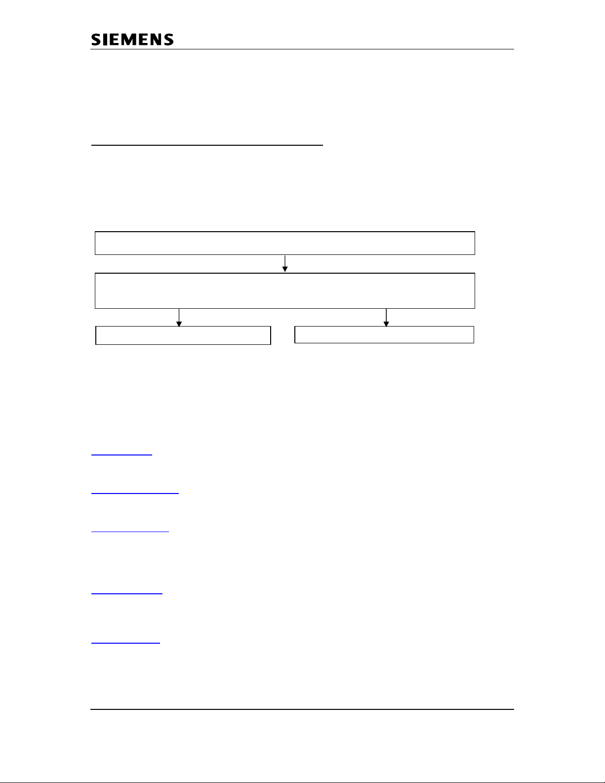
2 Procedures
Hidden service procedures for the handset and base stations.
Note: The service procedures are confidential.
2.1 Service procedures for Gigaset E45 handset
Read out IPUI of the handset (for identification purposes): menu-key, *, #, 0, 6, #
Press 1, 4 and 7 simultaneously and keep keys pressed
Switch on and keep key pressed until "SERVICE" is visible, then release
all keys
Press 4685463 (HOTLINE
This code performs a fundamental reset on
the handset. All settings are reset to factory
defaults. Handset is still registered to base.
Service-menu is displayed with following items:
SW-version, QS-data, Speechpath test, Battery
mode, DSP-parameters, Metering mode,
Measure time, Working time, SAR.
Red items are only for Development Department
or Quality Assurance and not explained here!
SW-version:
Read out SW-version and IPUI (international portabl e user identity) of
handset. IPUI is a unique number (like IMEI) that could be used for identification.
Speechpath-test:
Switches a direct loop between microphone and loudspeaker.
This enables a check of the speechpath by blowing in the microphone.
Metering mode:
Press o.k. to activate an information line during normal operation
mode and leave the service menu afterwards.
Example: 100 - 0 - 02 - 016 - 100
RX-level - Frequency - Time slot - Base code - Bit error rate (100 = 100% o.k.)
Measure time:
Changes the measure time of the metering mode (change is not
necessary).
Working time:
Read out the time for which the handset has been switched on.
Example: 100h means handset has been switched on for 100 hours.
It can only be reset at WSC.
Confidential 3 COM CPE CC RCT
J. Junggebauer
Version 1.2 September, 2005
Page 4
Communications
2.2 Service procedures for Gigaset E450 and 455
Press:
Pos. acknowledge tone (rising sequence of notes) = Procedure has been accepted.
Read out RFPI number of base station
Pause after access code
and
length of dial pause ("P")
Pause after si g nal-key
Automatic attenuation correction
(dependant on country)
Time for end of call identification
(to distinguish between 2 ringing pulses of
one call with long pauses between pulses
and 2 separat e calls)
Hook-flash-prevention (cradle switch
identification) (short press on cradle switchkey is extended by SW to prevent that it is
interpreted as a press on the flash-key)
Pause after line seizure
Music on hold
Suppress first call if SMS is activated
Switch SMS functionality
System PIN reset
Programming data on an address
Read out SW-version
(decimal figures)
Range of ringing frequency recognition
Dial pulsing:
pulse pause ratio (make break ratio)
CLIP list activation
Off-hook CLIP activation 4 76200 6 0 = off 1 = on
Approval test
Working time
DTMF-CLIP mode (Norway / Denmark)
"menu-key", 5, 5, 9, ABCD (see table below), o.k.
Feature A B C D (Option)
1 - 0 1 - 1 1 = 1 sec.
2 = 2 sec.
3 = 3 sec.
4 = 6 sec.
1 - 2 1 = 800 ms
2 = 1600 ms
3 = 3200 ms
1 - 3 0 = off
1 = on
1 - 4 0 = 4 sec.
1 = 5.5 sec.
2 = 7 sec.
3 = 11 sec.
4 = 2.5 sec.
1 - 5 0 = 800 ms
1 = 2000 ms
1 - 6 1 = 1 sec.
2 = 3 sec.
3 = 7 sec.
1 - 7 0 = off 1 = on
1 - 9 0 = no 1 = yes
2 6 0 = off 1 = on
3 76200 - 4 76200 1 Specific code needed
4 76200 2 Example: 0100200 …
01 = SW-variant
002 = SW-versi on
00 = Revision
4 76200 3 0 = 20- 60 Hz
1 = 15- 75 Hz
2 = other settings
4 76200 4 0 = 1.5 : 1
1 = 2 : 1
4 76200 5 0 = on 1 = off
6 76200 5 7 - 1 - see **
7 - 2 0=Norway 1=Denmark
Confidential 4 COM CPE CC RCT
J. Junggebauer
Version 1.2 September, 2005
Page 5

Communications
** Working time
Read out the time for which the base station has been switched on.
Example: 100h means the base station has been switched on for 100 hours.
It can only be reset at WSC.
Service Settings:
Read out service settings of the base station via handset during an external call
(Hotline feature).
Preconditions:
Line seized, number dialled and connection is established for at least 8 seconds.
Press softkey “options”, select “service info” and confirm with “o.k.”.
1: RFPI of base station
2: IPUI of current handset (read from the base station EEPROM)
3: Byte 1: registered handsets (lowest 6 bits)
DECT Subscription place s : for each bit: 1= s ubscribed 0= e mpty
Byte 2: Repeater mode (highest bit), space, dial mode (2 bits), space, flash
time (3 bits)
Byte 3 and 4: work i n g tim e co unter
4: SW-Version: Variant[2] Version[3] Revision[2] User_ID[3] Local increment[2].
Fundamental reset:
Disconnect mains. Press paging key on base station and hold down.
Plug in AC- adapter. Hold key pressed for more than 3 seconds.
Release paging key. The base station is now set to factory defaults.
The system-PIN is reset to 0000 and all mobile units are deregistered.
If a handset was registered only to this base station before the reset, it can be
registered automatically after a location update with the base station (after appr.
30 seconds or after picking up the handset (off hook key).
(menu, 54971):
Repeater mode: 1=on, 0=off
Dial mode: 0=Tone, 1=Pulse, 2=Tone-Earth
Flash time (ms): 0=80, 1 = 100, 2=120, 3=180, 4=250, 5=300, 6=600,
7=800
Confidential 5 COM CPE CC RCT
J. Junggebauer
Version 1.2 September, 2005
Page 6
Communications
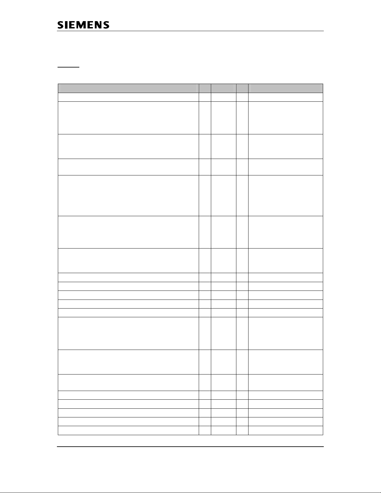
3 Lasered imprint and sticker on microprocessor
These are the 2 important numbers on the info sticker.
The first number shows the type of the phone.
Example: - S30 means new component
S36 means swap component
- 852 stands for analogue Gigasets
- S16xx means Portfolio 2004 (here: 1718 = handset for E455 base).
- The following 2 characters indicate the country .
B1 means Germany (Siemens); A1 means Germany (PTT)
C1 Austria, C4 Australia, N1 France, V1 Ireland, K1 Italy,
S2 Poland, S3 Russia, S7 Hungary, B4 Turkey, L1 UK,
F1 Switzerland, M1 Netherlands, D1 Spain, .....
- The following character shows the variant .
Euro-PTT-Version, Base with Classic-/ Comfort handset...
- The last character indicates the colour.
The second number indicates the date of production.
CT stands for Bocholt.
The next characte r shows the year of production.
S = 2004, T= 2005 …
The last character sh ows the mont h of pr o d uction.
1-9 = January to September
O = October
N = November
D = December
Sticker on Microprocessor:
S30852-S1718-B101
...............
CT/T9
Date: July,11,2005
T711
L
I
N
T
I
M
E
Partnumber of board
E
S
T
A
T
E
Confidential 6 COM CPE CC RCT
J. Junggebauer
Version 1.2 September, 2005
Page 7

Communications
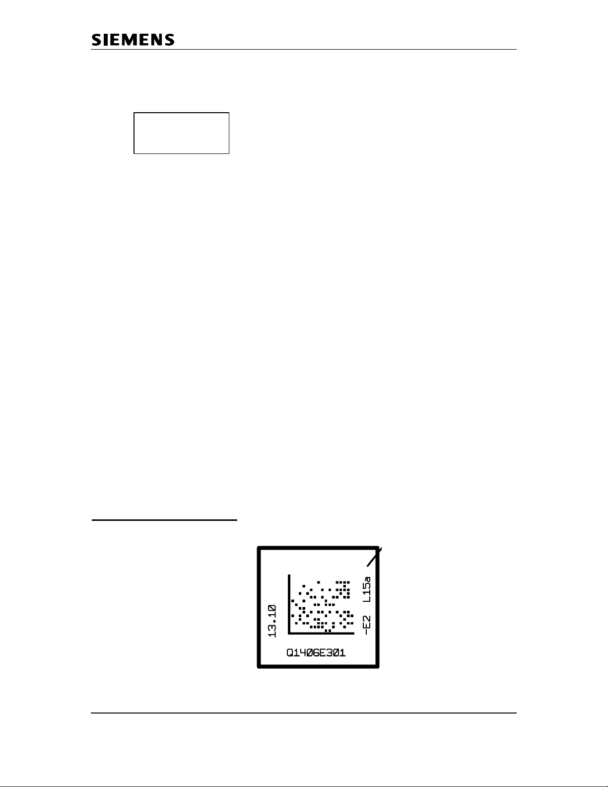
4 Test setup recommendation
- Gigaset 4170 or 4175 to be used as a PBX
- Gigaset handset (with charger) which is registered on Gigaset 4175
- Gigaset E450 base station to test customer‘s handset
- Gigaset E45 handset to test customer‘s base station
- 2 multimeters:
- 1 voltmeter to measure the PSTN line voltage of the customer‘s base
- 1 amperemeter to measure the AC-current of the AC-adaptor connected
to the customers base station
- 2 modified cables:
- 1 AC adaptor where the cable is opened (cut off) for the amperemeter
- 1 Mini-Western PSTN cable with a parallel cable for the voltmeter
See next page for the setup.
Confidential 7 COM CPE CC RCT
J. Junggebauer
Version 1.2 September, 2005
Page 8
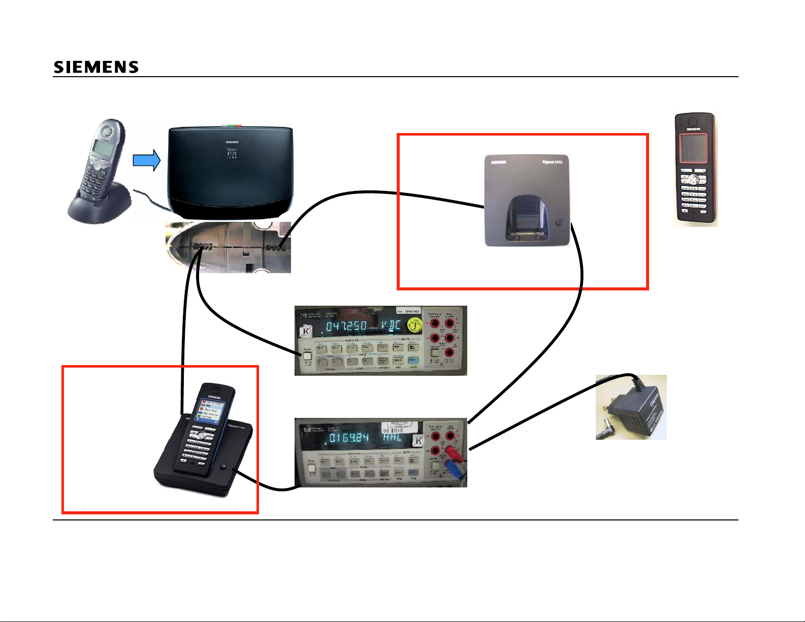
Communications
Handset is
registered
to G4175
Connection for corded phones
under the bottom of G4175
system or base station test
handset test
golden device base for
testing customer‘s handset
Measurement
of carge
current
golden device
handset for
testing
customer‘s
base station
customer‘s system
Measurement of PSTN voltage
Measurement of AC-adaptor current
Confidential 8 COM CPE CC RCT
J. Junggebauer
Version 1.2 September, 2005
Prepared power supplies
(1 wire opened for
current measurement)
Page 9
Communications
4.1 Test steps handset
- Try to verify the customer‘s fault description. If necessary perform a
long term test (sporadic problems (e.g. RF) or charging problems).
- Complete test (e.g. if no customer‘s fault description available)
- Switch the customer‘s handset on.
- Check function of display.
- Register handset on golden device base station.
- Set up an external call to the test handset that is registered to the G4175.
- Do an audio test in transmit and receive direction (speech).
- Check if the handset switches on hook when putting it in the charger.
- Control the charging current with the help of the customer‘s base station or
use the appropriate golden device base station / charger.
Current consumption in charger is appr. 160-170 mA. If a base is used for test:
Add the normal current consumption of the base station to the charge current.
- Do a ringer test on customer‘s handset by receiving an incoming call.
- Test the RF-range of the customer‘s handset by walking to a marked line.
4.2 Test steps base station
- Try to verify the customer‘s fault description. If necessary perform a
long term test (sporadic problems (e.g. RF) or charging problems).
- Complete test (e.g. if no customer‘s fault description available)
- Check the current consumption of the customer‘s base station.
- Control the PSTN voltage.
- Register golden device handset on customer‘s base station.
- Pick up the handset and check the PSTN voltage.
- Set up an external call to the test handset that is registered to the G4175.
- Do an audio test in transmit and receive direction (speech).
- Control the charging current with the help of a golden device handset.
Charge current consumption appr. 160-170 mA.
Add the normal current consumption of the base station to the charge current.
- Do a ringer test on customer‘s base station by receiving an incoming call.
- AM base stations: Test the function of the answering machine by leaving
a message on the AM. Check the quality of the message afterwards.
- Test the RF-range of the customer‘s handset by walking to a marked line.
Do a fundamental reset on the handset / base station in case of swap.
Confidential 9 COM CPE CC RCT
J. Junggebauer
Version 1.2 September, 2005
Page 10
Communications
5 Block diagrams
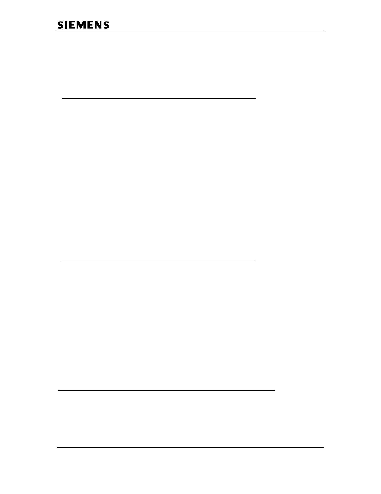
5.1 Block diagram handset
Charging
contact
Akku-Pack
2 x 1.2V
EMC-Filter
I
Charging-
Converter
Akku
VBAT (3.6V max)
3 V
Switch
DC/DC
LDO
1.8V
LDO
2.5V
Power-
Control
on/off-key
RF-Module
NSC
BMC
Temperatur-
sensor
Keypad
SC14432
GenDSP
µP CR 16
22k RAM 5M Flash
MWI
KEY SP
AFE
Class-D
ACCESS BUS1
E²PROM
8 kB
Adaption
Unit
Colour Grafik
LCD-Modul
HSG
SPI
Confidential 10 COM CPE CC RCT
J. Junggebauer
Version 1.2 September, 2005
Page 11
Communications
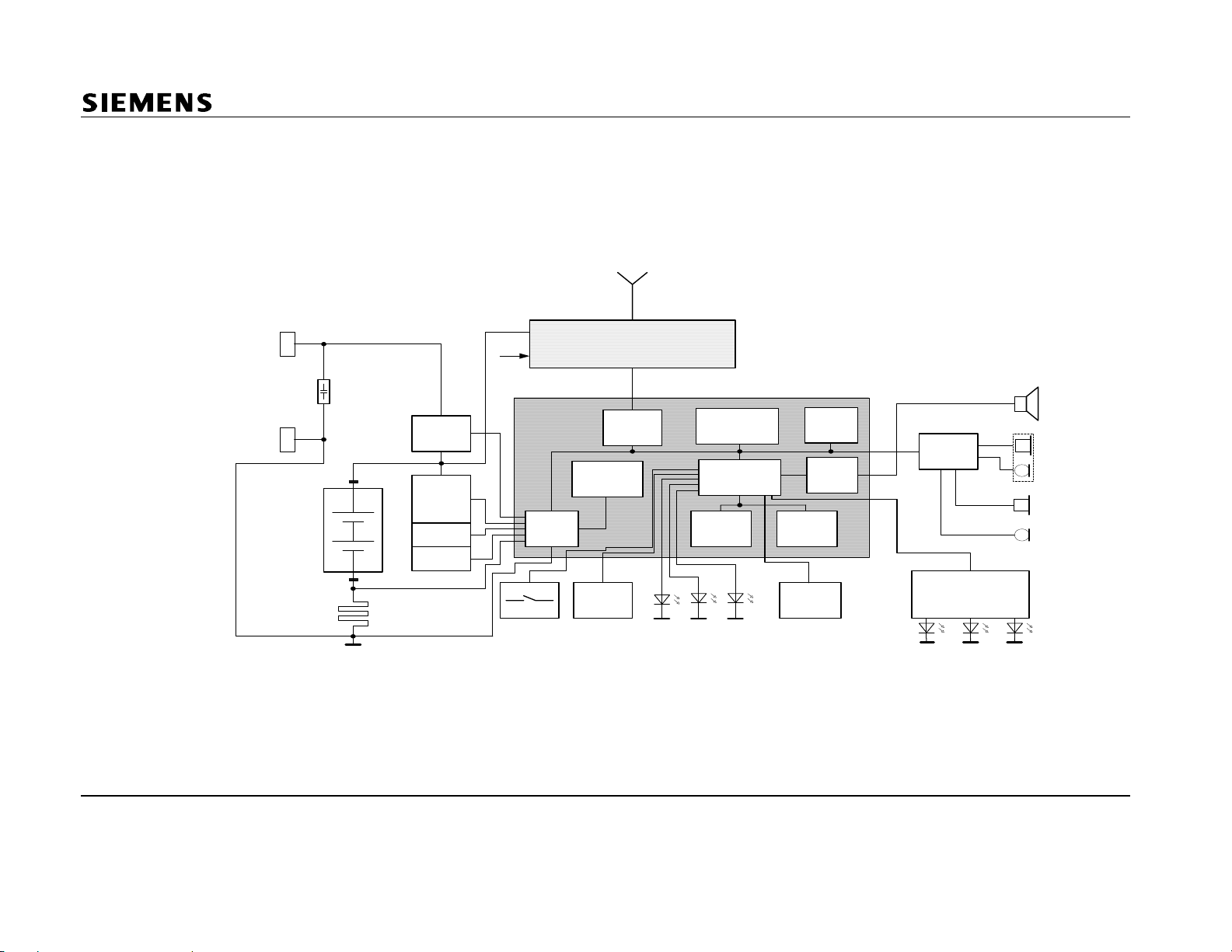
5.2 Block diagram E450 base station
Confidential 11 COM CPE CC RCT
J. Junggebauer
Version 1.2 September, 2005
Page 12
Communications
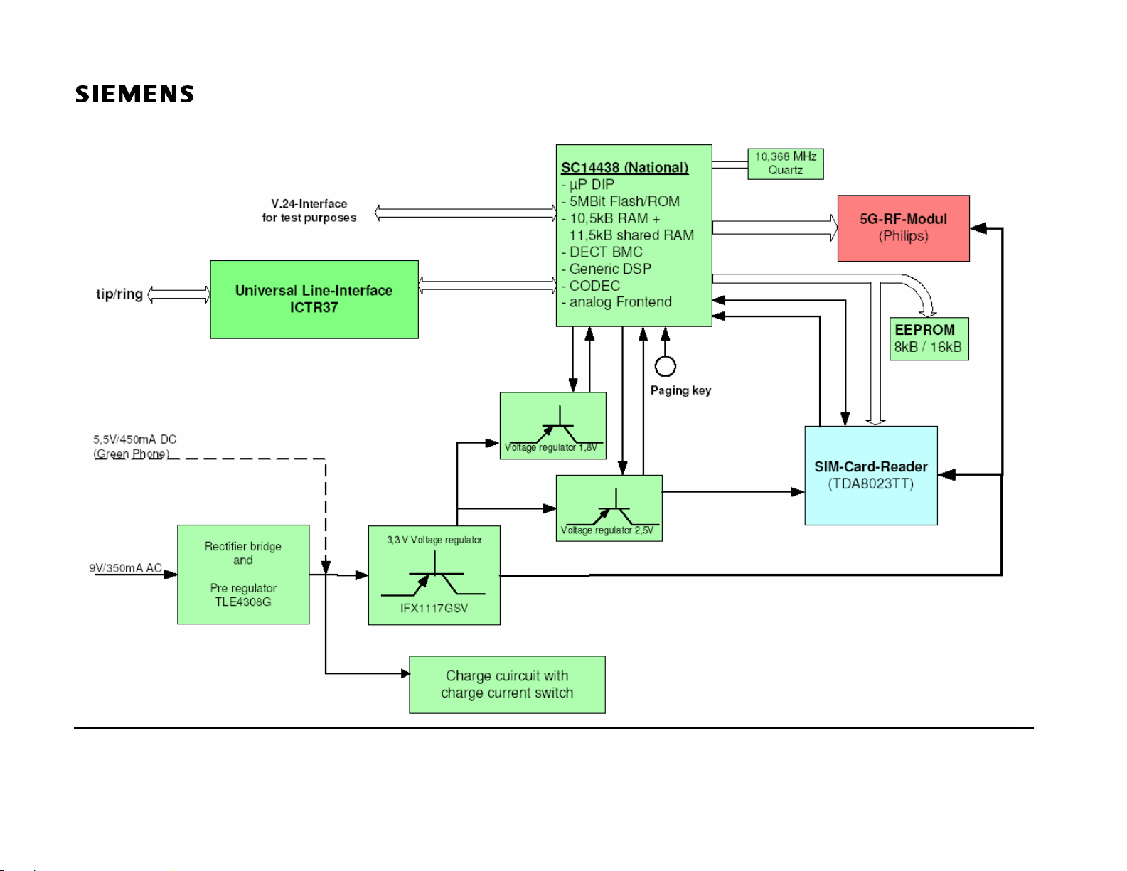
5.3 Block diagram of universal line interface ICTR37
Confidential 12 COM CPE CC RCT
J. Junggebauer
Version 1.2 September, 2005
Page 13
Communications
plug
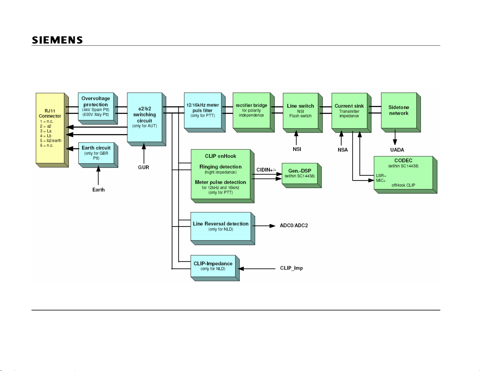
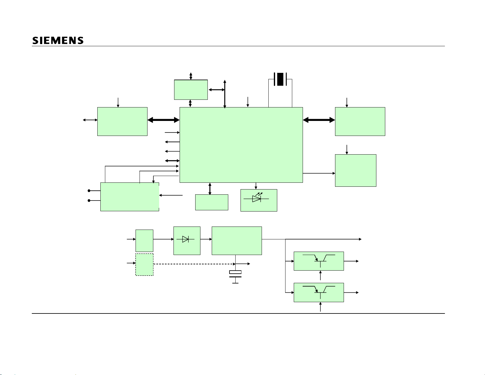
5.4 Block diagram E455 base station
+3V3
line (a/b)
Line Interface
VBAT
VR1_CTRL
VR2_CTRL
CHARGE_DETEC T
CHARGE_CURRENT
Charging Circuit
(only Oslo-AM)
JTAG
P.S.
plug
-C501
CHARGE
+8V0
SIM-Card
SIM-Card
Reader w
TDA8023
Keypad
(8keys)
Test Inte rfac e
I2C
VEGA Bluebird
Infineon
TLE 4308 +
IFX1117
+1V8,
+2V5,
+3V3
1 LED
10,368MHz
SPEAKER
SPKENQ
+3V3
RF (Philips)
+8V0
Speaker Amp
MC34119
(only Oslo-A M )
+3V3
(
VDDIO, RF part, LineInt.)
P.S.
switch
mode
-C?
+8V0
Confidential 13 COM CPE CC RCT
J. Junggebauer
Version 1.2 September, 2005
VR1_CTRL
VR2_CTRL
+2V5
(VDDA, VDDINT, VDDO
w Sense Pin)
+1V8
(VDDC, VDDPLL)
Page 14

Communications
6 Repair of E45 handset
ESD regulations have to be followed in the complete repair process!
6.1 Special equipment and tools
Opening-tool G2000/4000 F30032-P175-A1
Opening pliers G5000 F30032-P271-A1
Torque screwdriver Torx 5+
Helpful selfmade tools:
1. Foam shape:
Take a piece of foam, cut and stick together the parts, so that it looks like the tool on
the picture. This is a good help for the display soldering process, because the lower
case shell, which acts as a display soldering jig can be fixed in this foam shape.
2. Testhousing:
Take a lower case shell of a handset and cut the latches on both sides with a
sidecutter.
That allows you to open both case shells easily because they are only fixed by the
latches on the bottom and on the top.
Confidential 14 COM CPE CC RCT
J. Junggebauer
Version 1.2 September, 2005
Page 15

Communications
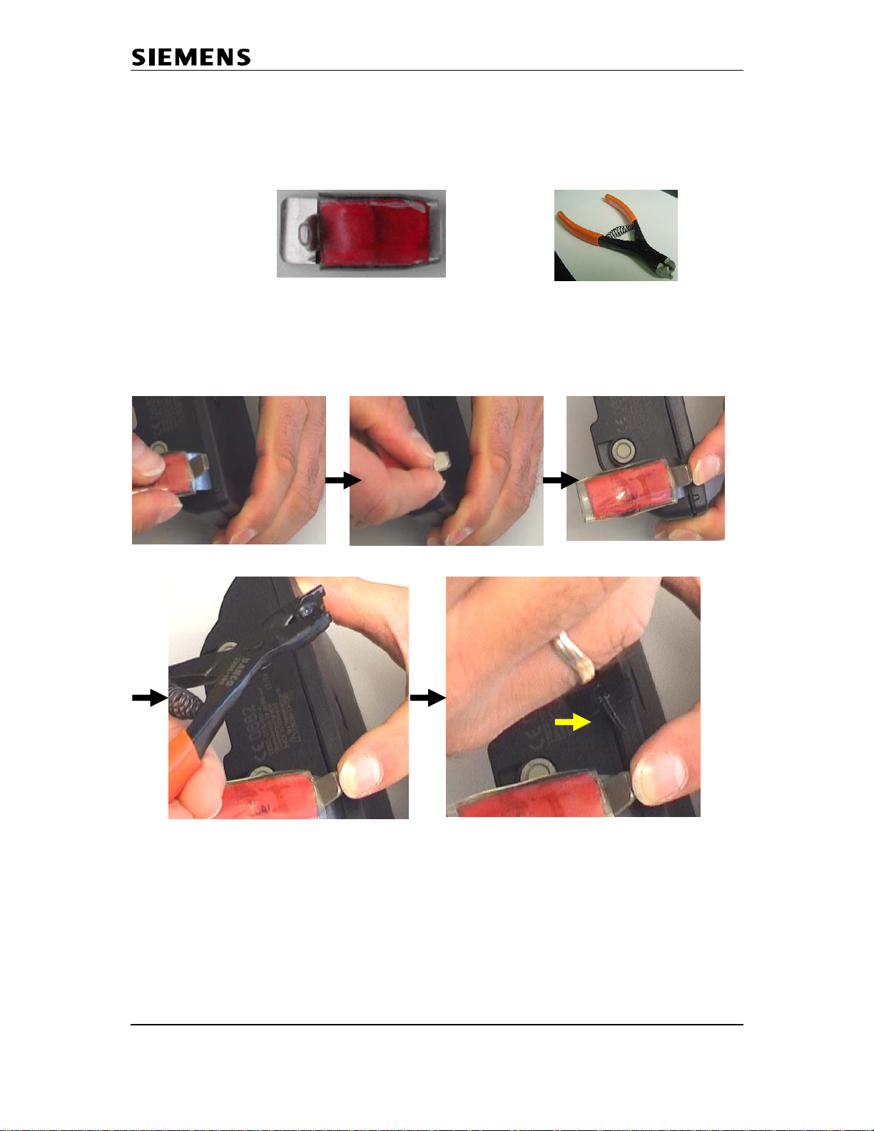
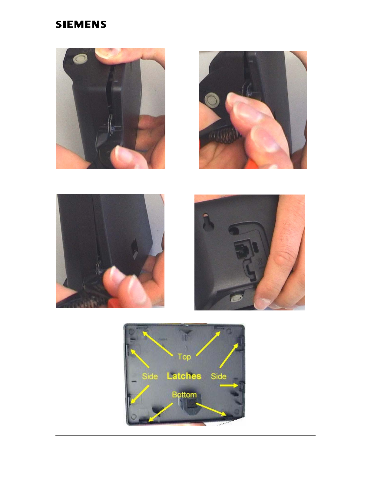
6.2 Disassembling of handset
Turn the belt clip and take it off. Remove the battery cover. Take out the battery.
Unscrew the 6 screws with a torx 5+ screw driver.
Insert the open pliers G5000 in one of the charger holes and press. Do the same
in the other hole and pull on the case shells to open the housing.
Confidential 15 COM CPE CC RCT
J. Junggebauer
Version 1.2 September, 2005
Page 16

Communications
6.3 Assembling of handset
Use the exploded view as a help to see where the components are located.
To ensure that the device is splash water proof and dust proof (IP54) always take a
new housing.
Insert keypad, receiver and afterwards PCB in upper case shell.
Fix loudspeaker in lower case shell.
Close handset by pressing both case shells together.
Screw the 6 screws with a torque screwdriver torx 5+ with a torque of 23 Ncm.
6.4 Exploded view of handset
Confidential 16 COM CPE CC RCT
J. Junggebauer
Version 1.2 September, 2005
Page 17
Communications
6.5 Board Layout of handset
Confidential 17 COM CPE CC RCT
J. Junggebauer
Version 1.2 September, 2005
Page 18

Communications
V
6.6 Humidity or liquid damage
Diagnosis code IRIS:
- Boards with oxidation on the keypad side do not have to be scrapped if the vias
are not affected by green oxidation layer. Æ Clean the PCB.
- Boards with humidity damages on the component side have to be scrapped.
Check all electronic components on the back side. Do not open the RF-Part.
Remaining flux on the component side could look similar to a humidity damage (white
deposits) but it will disappear when heating it up with a hot air blower.
no scrap:
Scrap:
Check also area under display!
61000 (DEVICE / MOISTURE DAMAGE)
ia
Confidential 18 COM CPE CC RCT
J. Junggebauer
Version 1.2 September, 2005
Page 19
Communications
6.7 Receiver faulty
Affected unit:
Diagnosis code IRIS:
Repair level:
Components:
Needed equipment:
Working material:
Diagnosis:
The diaphragm of the earphone could be affected by deposits with increasing age.
There will be a higher attenuation when measuring RLR (receiving loudness rating).
In most cases the earphone capsule is defective.
If there is no noise audible on the earphone when making a sidetone check it’s also
possible that the wire of the coil is broken.
Check the resistance of the coil with a multimet er .
The typical resistance is appr. 32 (+/- 2) ohm. In other cases replace it.
Repair:
Replace receiver.
Test:
Put the repaired board in a testhousing.
Make a sidetone check by blowing into the microphone and checking the volume
of the noise on the earphone.
If there is a telephone tester with acoustic testhead do an RLR-test and check
whether the attenuation is o.k..
Handset
72100 (ACOUSTICS / RECEIVING / EARCAP)
Level 1
Receiver
Multimeter
None
Confidential 19 COM CPE CC RCT
J. Junggebauer
Version 1.2 September, 2005
Page 20
Communications
6.8 Loudspeaker faulty
Affected unit:
Diagnosis code IRIS:
Repair level:
Components:
Needed equipment:
Working material:
Diagnosis:
Do a sidetone test (service-menu) in order to check the sound of the speaker.
If there is no sound, check the resistance of the coil with a multimeter.
The typical resistance is appr. 4 ohm. In other cases replace it.
Repair:
Replace loudspeaker.
Test:
Put the repaired board in a testhousing.
Do a sidetone test by blowing into the microphone and checking the volume
of the noise on the loudspeaker.
Handset
72200 (ACOUSTICS / RECEIVING / LOUDSPEAKER)
Level 1
Loudspeaker
Multimeter
None
Confidential 20 COM CPE CC RCT
J. Junggebauer
Version 1.2 September, 2005
Page 21

Communications
6.9 Display cover broken or scratched
Affected unit:
Diagnosis code IRIS:
Repair level:
Components:
Needed equipment:
Working material:
Diagnosis:
Display cover broken or scratched.
Repair:
Replace display cover.
Open the 2 latches on the bottom with a screwdriver(1).
Then lift the display carefully until the 2 latches on the top open (2).
To reassemble the display you just need to press the new cover gently on its place.
Test:
Do a display test after replacement.
Handset
23100 (DISPLAY / MECHANICAL DEFECT / SCRATCHES)
Level 1
Display cover
Screwdriver
None
(2)
(1)
Confidential 21 COM CPE CC RCT
J. Junggebauer
Version 1.2 September, 2005
Page 22
Communications
6.10 Display module faulty
Affected unit:
Handset
Diagnosis code IRIS:
21200 (DISPLAY / PERFORMANCE / LINE-/COLUMN ERROR)
21100 (DISPLAY / PERFORMANCE / NO LETTERS)
23200 (DISPLAY / MECHANICAL DEFECT / DISPLAY BROKEN)
Repair level:
Level 2.5
Components:
Display module
Needed equipment:
50 watts soldering station Weller WTCP 50 or WS (D) 50,
Soldering tip FP7, small soldering tip
Working material:
Flux Kester 952 S, scotc h t ap e
Diagnosis:
Missing lines, columns, display does not work at all or display (LCD) broken.
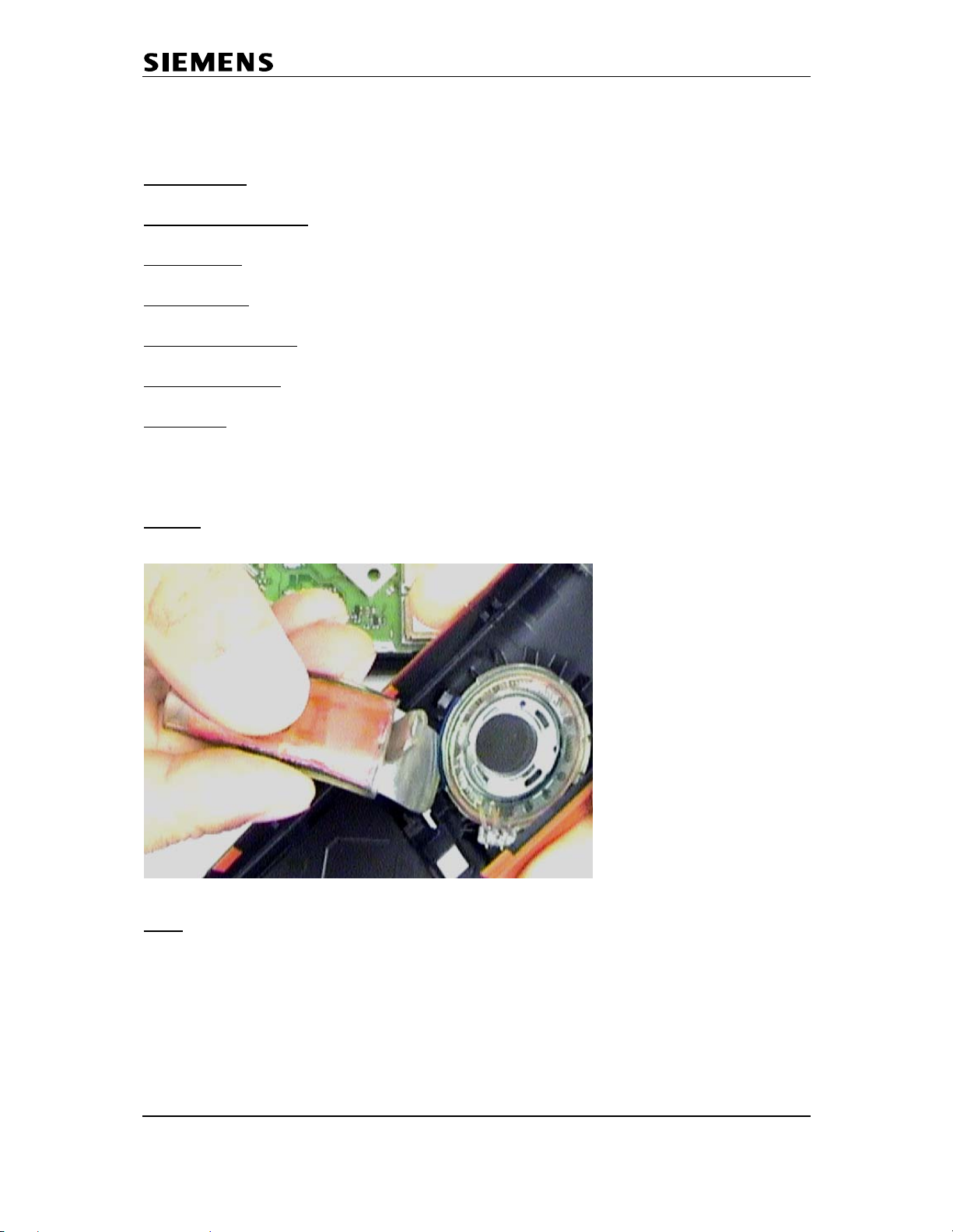
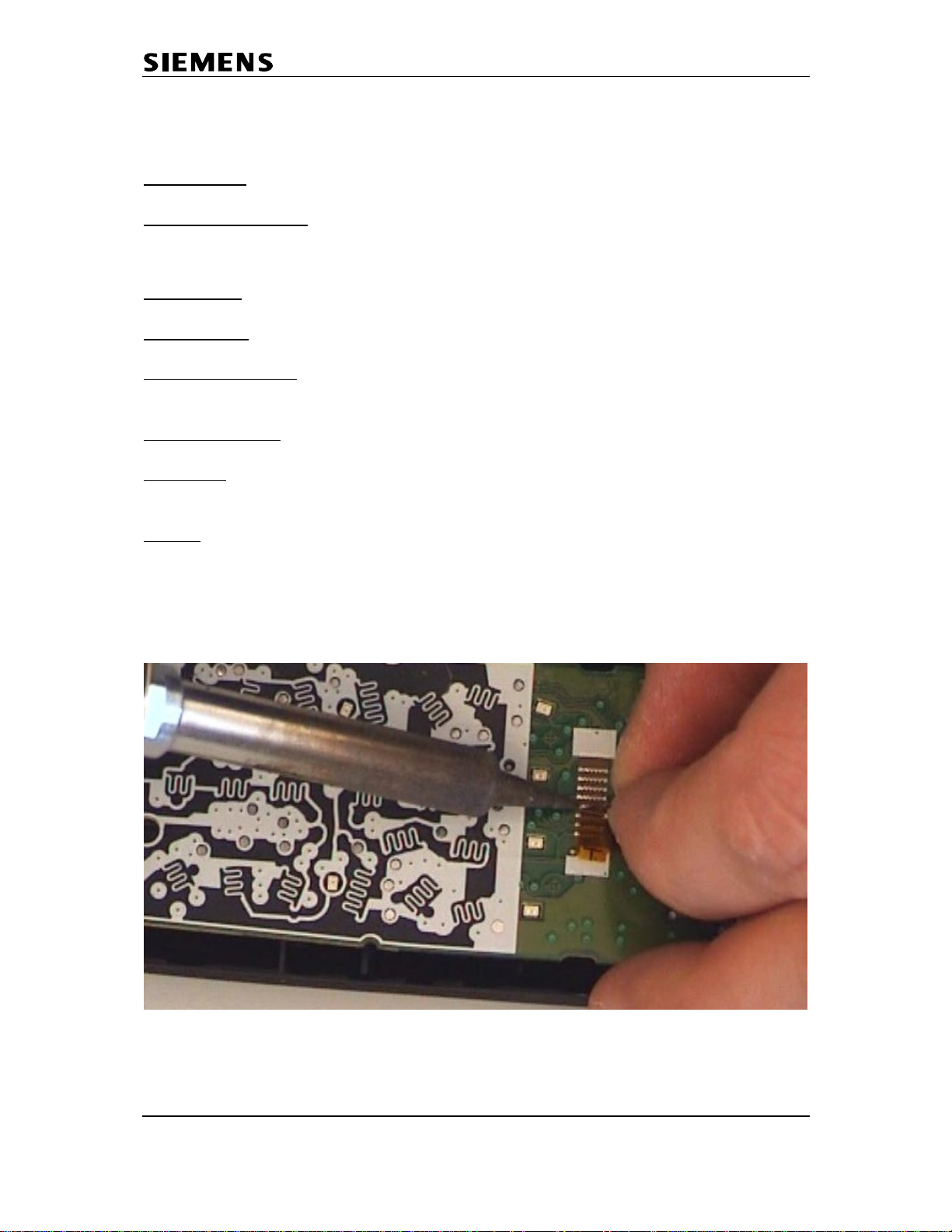
Repair:
Adjust the soldering station to 370°C (only for WS(D) 50).
Insert board in testhousing case shell (see chapter 6.1).
Fix case shell in foam shape.
Release faulty display by soldering the soldered joints and pulling the display foil as
described on the picture below.
Pictures are taken from G5000.
Confidential 22 COM CPE CC RCT
J. Junggebauer
Version 1.2 September, 2005
Page 23

Communications
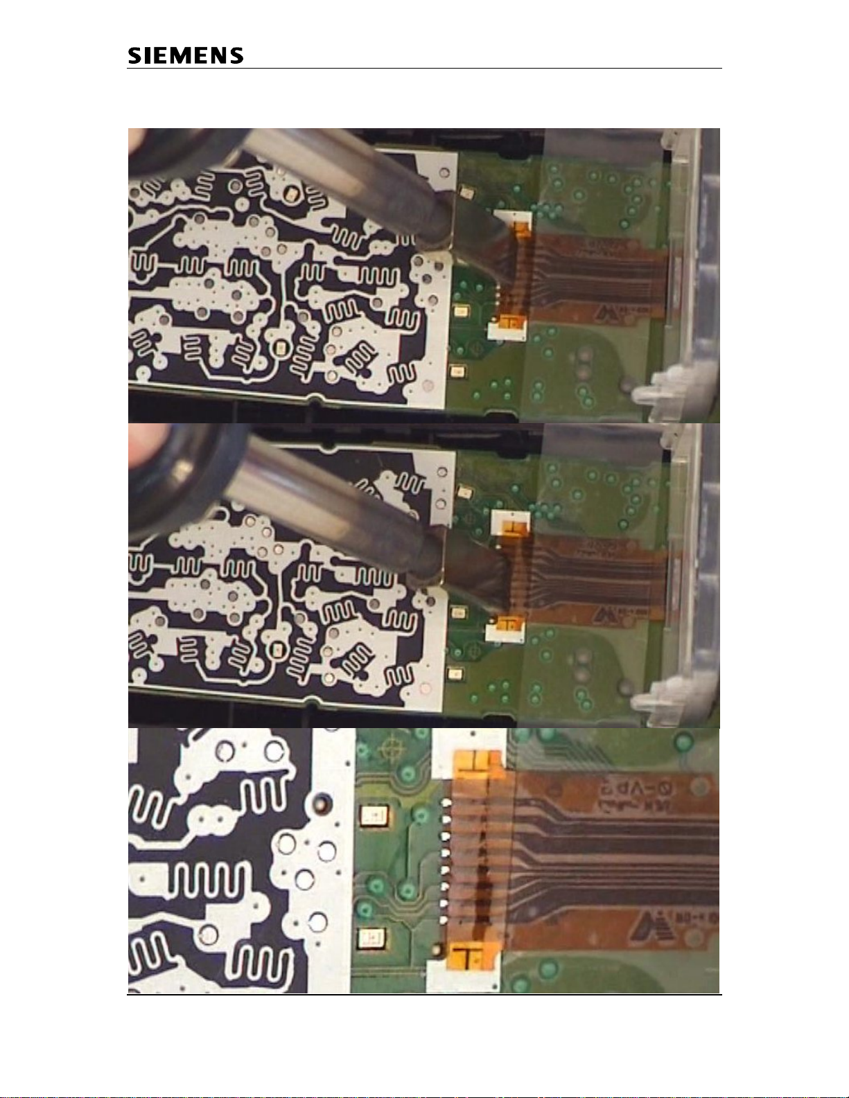
Put some flux on the pads and resolder them until the surface is even.
Take a new display and a piece of tape and fix it on the display foil.
Confidential 23 COM CPE CC RCT
J. Junggebauer
Version 1.2 September, 2005
Page 24

Communications
Align the display foil on the PCB and fix it.
Put some flux between foil and pads.
Confidential 24 COM CPE CC RCT
J. Junggebauer
Version 1.2 September, 2005
Page 25
Communications
Put the soldering tip FP7 on the soldering iron and solder the display in 2 steps as
described in the picture below. The result should look like the last picture.
Confidential 25 COM CPE CC RCT
J. Junggebauer
Version 1.2 September, 2005
Page 26

Communications
Fix the display foil with a finger and gently remove the tape.
Test the soldered connection by gently pulling the display foil.
Test:
Do a display test. Press 1,4 and 7 simultaneously and keep pressed while switching
on the handset. Release all keys.
Press a key. You must test patterns on the display. Press another key in order to
change test patterns. Do this a few times until the first test pattern is visible.
Confidential 26 COM CPE CC RCT
J. Junggebauer
Version 1.2 September, 2005
Page 27

Communications
6.11 Microphone faulty
Affected unit:
Diagnosis code IRIS:
73110 (ACOUSTICS / TRANSMITTING / MICROPHONE / NO FUNCTION)
73170 (ACOUSTICS / TRANSMITTING / MICROPHONE / LOW VOICE LEVEL)
Repair level:
Components:
Needed equipment:
Working material:
Diagnosis:
The diaphragm of the microphone is affected by humidity or nicotine with increasing
age or the microphone could be electrically faulty. There will be a higher attenuation
when measuring SLR (sending loudness rating). In most cases the microphone is
defective.
Repair:
Remove the microphone by desoldering the 2 solder joints.
You can also heat up both pins simultaneously with a broad soldering iron tip and
turn the board upside down, letting the microphone fall out.
Clean pads with desoldering wick and replace it by a new component afterwards.
Attention: Avoid excessive heat (2 seconds maximum)!
Test:
Put the repaired board in a testhousing.
Make a sidetone check by blowing into the microphone and checking the volume
of the noise on the earphone.
If there is a telephone tester with acoustic testhead make a SLR-test and check
whether the attenuation is o.k..
Handset
Level 2.5
Microphone
Soldering iron
Desolder wick, solder
Confidential 27 COM CPE CC RCT
J. Junggebauer
Version 1.2 September, 2005
Page 28

Communications
7 Repair of basestation
7.1 Disassembling of base station E450
ESD regulations have to be followed in the complete repair process!
Needed material:
Case opener: F30032-P85-A1
Unscrew the 3 screws of the lower case shell.
Insert the case opener between both case shells (location 1) and press until the
latches open. Insert the case opener at location 2 and do the same to open the other
latches.
Suitable screw driver with cross recess,
1
1
2
2
Confidential 28 COM CPE CC RCT
J. Junggebauer
Version 1.2 September, 2005
Page 29
Communications
7.2 Disassembling E455
Needed material: Opening-tool G2000/4000 Case opener
F30032-P175-A1 F30032-P85-A1
Insert the opening tool by pushing and turning it up until it gets stuck between both
case shells, turn it down and fix it with a finger while inserting and pressing the case
opener.
Confidential 29 COM CPE CC RCT
J. Junggebauer
Version 1.2 September, 2005
Page 30
Communications
Do the same on the side latch and afterwards on the 2. bottom latch.
Open the remaining side latch. Lift the back case shell upwards.
Confidential 30 COM CPE CC RCT
J. Junggebauer
Version 1.2 September, 2005
Page 31

Communications
7.3 Assembling of base stations
Needed material:
E450:
Put charger contact springs in upper case shell.
Insert keypad.
Put PCB in upper case shell.
Attach the other case shell and close the device by screwing the 3 screws in the
lower case shell.
Make sure that the charging contact springs are fixed correctly.
E455:
Insert keypad.
Put PCB in upper case shell.
Attach the other case shell and close the device by closing the latches.
suitable screw driver with cross recess
Confidential 31 COM CPE CC RCT
J. Junggebauer
Version 1.2 September, 2005
Page 32

Communications
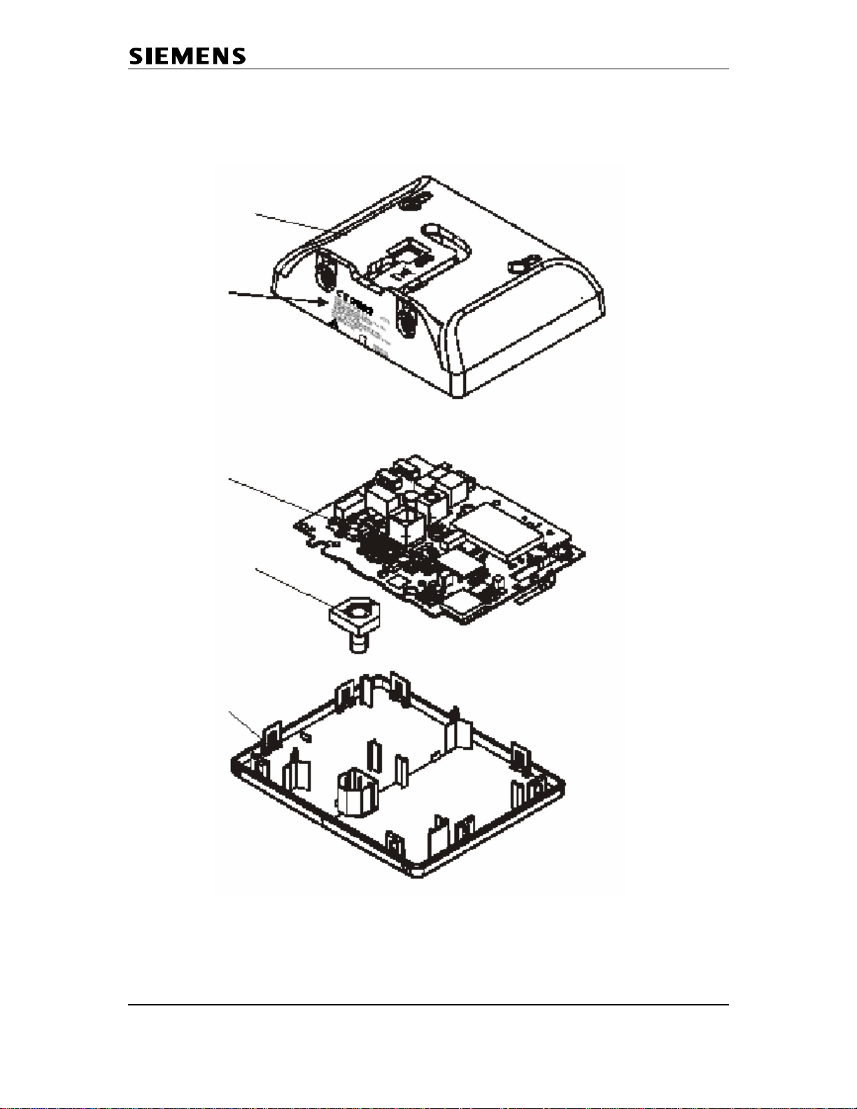
7.4 Exploded view E450
Confidential 32 COM CPE CC RCT
J. Junggebauer
Version 1.2 September, 2005
Page 33
Communications
7.5 Exploded view E455
Confidential 33 COM CPE CC RCT
J. Junggebauer
Version 1.2 September, 2005
Page 34
Communications
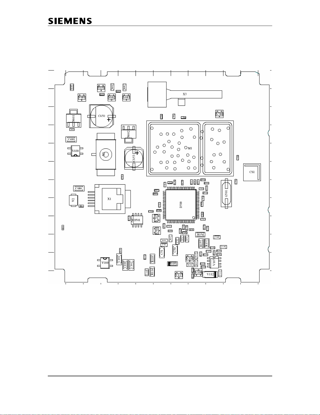
7.6 Board Layout E450
Confidential 34 COM CPE CC RCT
J. Junggebauer
Version 1.2 September, 2005
Page 35
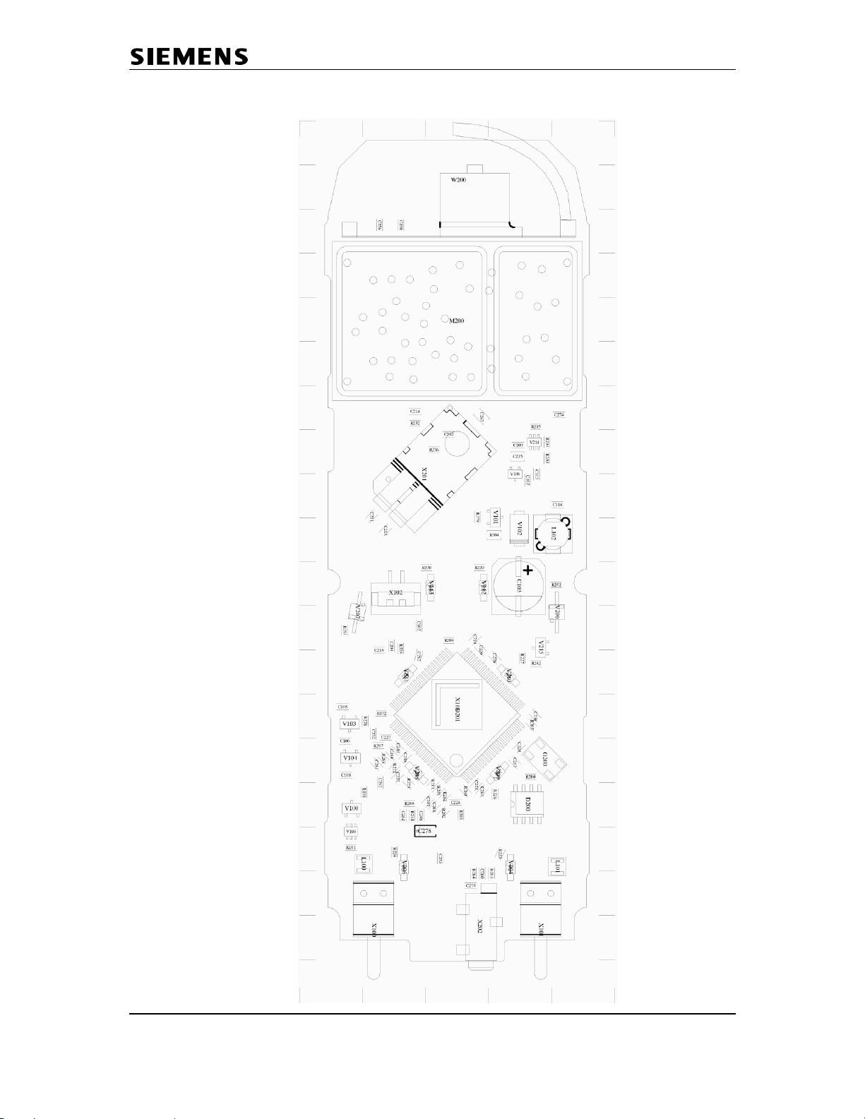
Communications
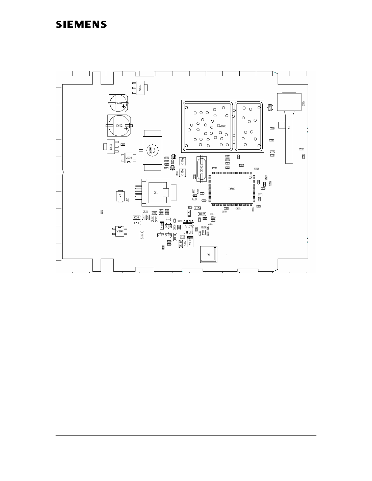
7.7 Board Layout E455
Confidential 35 COM CPE CC RCT
J. Junggebauer
Version 1.2 September, 2005
Page 36

Communications
7.8 Lightning stroke damage
Diagnosis code IRIS:
Scrap all base stations with lightning stroke damage.
Inspect the board regarding chipped components, black soot on the board or
components that look like those on the picture below.
62000 (DEVICE / LIGHTNING/OVER VOLTAGE)
Confidential 36 COM CPE CC RCT
J. Junggebauer
Version 1.2 September, 2005
Page 37

Communications
7.9 Charging problems
Affected unit:
Diagnosis code IRIS:
Repair level:
Components:
Needed equipment:
Working material:
Diagnosis:
The battery segment on the handset display doesn’t start blinking when charging.
Inspect the charger pads looking for small black holes on the surface.
Check charger contact springs.
Repair:
Roughen the surface with a glass fibre pen.
Solder the charger pads so that there is a thin layer of new solder on the joints.
Suck away surplus solder with desolder wick.
Roughen the surface with a glass fibre pen.
Replace charger contact springs.
If charger pads look o.k. only replace charger contact springs.
Test:
Assemble the base station.
Check if battery segment on display starts blinking when charging.
Gigaset E450
97000 (FUNCTIONALITY / DEVICE NO CHARGING)
Level 1
Charger contact springs, charger pads
Soldering iron, glass fibre pen
Desolder wick, solder
Confidential 37 COM CPE CC RCT
J. Junggebauer
Version 1.2 September, 2005
Page 38
Communications
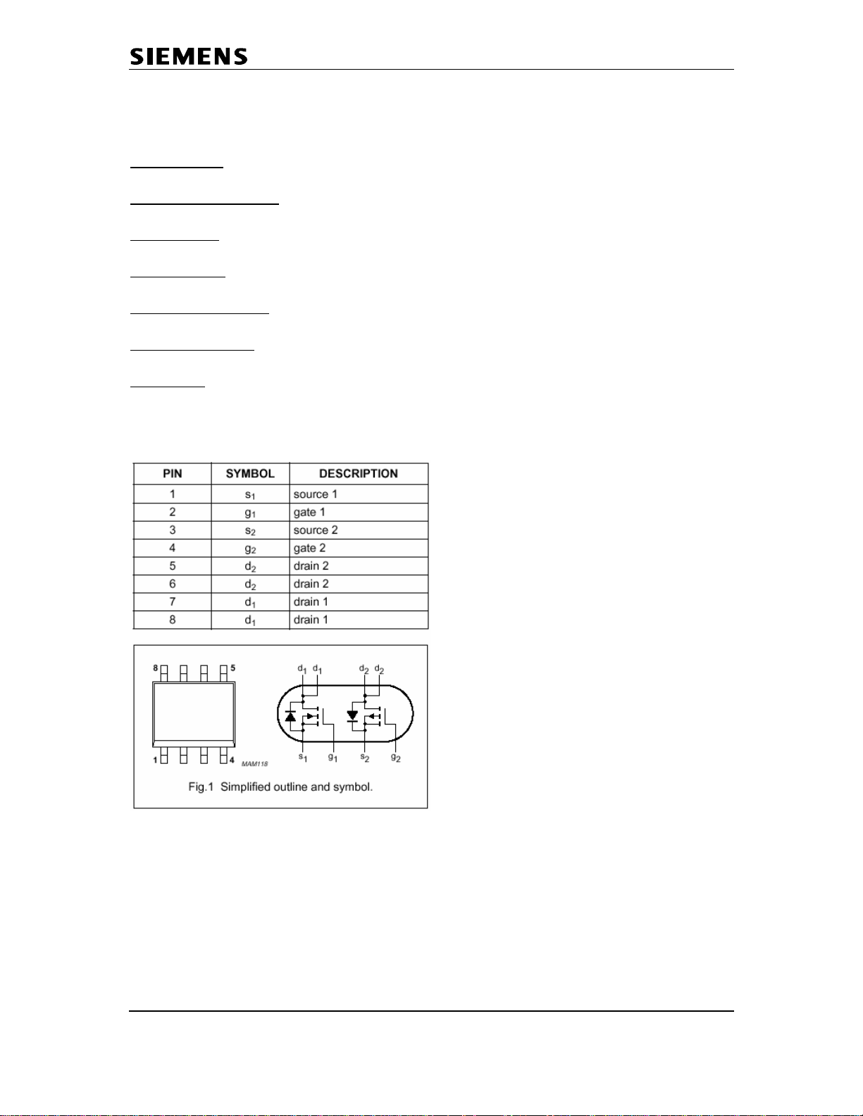
7.10 Line seizure problems
Affected unit:
Diagnosis code IRIS:
Repair level:
Components:
Needed equipment:
Working material:
Diagnosis:
Line seizure is not possible or connection can not be released. The IC PHC2300 (or
alternative component) consists of 2 transistors and is responsible for line seiz ure.
Measure the 2 transistors with a multimeter.
Gigaset E450, E455
93000 (FUNCTIONALITY / CALLING PROBLEMS)
Level 2.5
Philips IC PHC2300 or alternative component
Hot air blower, soldering iron, multimeter
Flux, solder
Confidential 38 COM CPE CC RCT
J. Junggebauer
Version 1.2 September, 2005
Page 39

Communications
Repair:
Desolder the IC and solder a new component with a hot air blower.
Put some flux on the joints and resolder them with a soldering iron.
If necessary put additional solder on the joints.
Test:
Assemble the base station and connect it to a PBX or PSTN line.
Pick up the handset and dial the extension of another phone connected to the PBX or
PSTN. Establish a connection, test the speech path and release it afterwards.
Pick up the other phone and dial the extension of the repaired phone.
Accept the call on the repaired phone.
If the line seizure in both ways wor ks the base station is o.k.
Confidential 39 COM CPE CC RCT
J. Junggebauer
Version 1.2 September, 2005
 Loading...