

Page 1

DIGISCAN M
System Manual
Start-up
Acquisition workstation, image reader,
viewing station
SP
© Siemens AG 2002
The reproduction, transmission or
use of this document or its contents
is not permitted without express
written authority. Offenders will be
liable for damages. All rights,
including rights created by patent
grant or registration of a utility
model _or_ design,_are_ reserved.
Register 4 English
Print No.: SPB7-420.815.01.04.02 Doc . Gen. Date: 11.02
Replaces: SPB7-420.815.01.03.02 66 31 159
Page 2

0 - 2 Revision
Chapter Page Revision
All All 04
Document revision level
The document corresponds to the version/revision level effective at the time of system delivery. Revisions to hardcopy documentation are not automatically distributed.
Please contact your local Siemens office to order current revision levels.
Disclaimer
The installation and service of equipment described herein is to be performed by qualified personnel
who are employed by Siemens or one of its affiliates or who are otherwise authorized by Siemens or
one of its affiliates to provide such services.
Assemblers and other persons who are not employed by or otherwise directly affiliated with or authorized by Siemens or one of its affiliates are directed to contact one of the local offices of Siemens or
one of its affiliates before attempti ng installation or service procedures.
DIGISCAN M Register 4 SPB7-420.815.01 Page 2 of 4 Siemens-Elema AB
System Manual Rev. 04 11.02 SPS-UD Solna, Sweden
Page 3

Contents 0 - 3
Page
1 _______Introduction ___________________________________________________1 - 1
Safety information . . . . . . . . . . . . . . . . . . . . . . . . . . . . . . . . . . . . 1 - 1
General remarks. . . . . . . . . . . . . . . . . . . . . . . . . . . . . . . . . . . 1 - 1
Laser safety . . . . . . . . . . . . . . . . . . . . . . . . . . . . . . . . . . . . . 1 - 1
Documents required. . . . . . . . . . . . . . . . . . . . . . . . . . . . . . . . . . . 1 - 1
Tools, meters and appliances required . . . . . . . . . . . . . . . . . . . . . . . . . 1 - 2
General remarks. . . . . . . . . . . . . . . . . . . . . . . . . . . . . . . . . . . 1 - 2
Prerequisites . . . . . . . . . . . . . . . . . . . . . . . . . . . . . . . . . . . . . . 1 - 3
MAMMOMAT . . . . . . . . . . . . . . . . . . . . . . . . . . . . . . . . . . . . 1 - 3
DIGISCAN M . . . . . . . . . . . . . . . . . . . . . . . . . . . . . . . . . . . . 1 - 3
Hardcopy camera . . . . . . . . . . . . . . . . . . . . . . . . . . . . . . . . . .1 - 3
Important notes on start-up . . . . . . . . . . . . . . . . . . . . . . . . . . . . . . . 1 - 4
General remarks. . . . . . . . . . . . . . . . . . . . . . . . . . . . . . . . . . . 1 - 4
Network configuration . . . . . . . . . . . . . . . . . . . . . . . . . . . . . . . . 1 - 4
Shipment. . . . . . . . . . . . . . . . . . . . . . . . . . . . . . . . . . . . . . . 1 - 4
Software . . . . . . . . . . . . . . . . . . . . . . . . . . . . . . . . . . . . . . . 1 - 4
Start-up sequence. . . . . . . . . . . . . . . . . . . . . . . . . . . . . . . . . . . . 1 - 5
Abbreviations . . . . . . . . . . . . . . . . . . . . . . . . . . . . . . . . . . . . . . 1 - 7
2 _______Start-up of the acquisition workstation_____________________________2 - 1
General remark . . . . . . . . . . . . . . . . . . . . . . . . . . . . . . . . . . . . . 2 - 1
Start-up procedure . . . . . . . . . . . . . . . . . . . . . . . . . . . . . . . . . . . 2 - 1
Install service images . . . . . . . . . . . . . . . . . . . . . . . . . . . . . . . . . .2 - 1
Labeling . . . . . . . . . . . . . . . . . . . . . . . . . . . . . . . . . . . . . . . . . 2 - 2
Configuration of the barcode scanner. . . . . . . . . . . . . . . . . . . . . . . . . . 2 - 3
3 _______Installation and start-up of the image reader ________________________3 - 1
Installation and start-up . . . . . . . . . . . . . . . . . . . . . . . . . . . . . . . . . 3 - 1
Starting the M-Utility (three scenarios) . . . . . . . . . . . . . . . . . . . . . . . . . 3 - 1
Starting the M-Utility from the routi ne process mode (routine mode) . . . . . . . .3 - 1
Starting the M-Utility from the initialization process mode. . . . . . . . . . . . . . 3 - 2
Starting the M-Utility from the abnormality process mode. . . . . . . . . . . . . . 3 - 3
Exiting M-Utility . . . . . . . . . . . . . . . . . . . . . . . . . . . . . . . . . . . 3 - 3
DICOM installation . . . . . . . . . . . . . . . . . . . . . . . . . . . . . . . . . . . 3 - 3
Setting the configuration. . . . . . . . . . . . . . . . . . . . . . . . . . . . . . . . . 3 - 4
Backup . . . . . . . . . . . . . . . . . . . . . . . . . . . . . . . . . . . . . . . . . 3 - 8
Check HOSTS file . . . . . . . . . . . . . . . . . . . . . . . . . . . . . . . . . . . . 3 - 9
4 _______Start-up of the viewing station (option)_____________________________4 - 1
MagicView 1000. . . . . . . . . . . . . . . . . . . . . . . . . . . . . . . . . . . . . 4 - 1
Start-up procedure. . . . . . . . . . . . . . . . . . . . . . . . . . . . . . . . . .4 - 1
Software configuration. . . . . . . . . . . . . . . . . . . . . . . . . . . . . . . . 4 - 1
MammoReportPlus . . . . . . . . . . . . . . . . . . . . . . . . . . . . . . . . . . . 4 - 1
Start-up procedure. . . . . . . . . . . . . . . . . . . . . . . . . . . . . . . . . .4 - 1
Siemens-Elema AB Register 4 SPB7-420.815.01 Page 3 of 6 DIGISCAN M
Solna, Sweden Rev. 04 11.02 SPS-UD System Manual
Page 4

0 - 4 Contents
Page
5 ______ Start-up of the hardcopy camera ___________________ _______________5 - 1
Hardcopy camera requirements . . . . . . . . . . . . . . . . . . . . . . . . . . . . 5 - 1
Recommended hardcopy cameras . . . . . . . . . . . . . . . . . . . . . . . . . 5 - 1
6 ______ Function check ________________________________________________6 - 1
Switch on the system. . . . . . . . . . . . . . . . . . . . . . . . . . . . . . . . . . 6 - 1
Function check of the acquisition workstation . . . . . . . . . . . . . . . . . . . . . 6 - 1
Image transfer . . . . . . . . . . . . . . . . . . . . . . . . . . . . . . . . . . . 6 - 1
Filming (option) . . . . . . . . . . . . . . . . . . . . . . . . . . . . . . . . . . . 6 - 2
Function check of the viewing station (option) . . . . . . . . . . . . . . . . . . . . . 6 - 4
MagicView 1000 . . . . . . . . . . . . . . . . . . . . . . . . . . . . . . . . . . 6 - 4
MammoReportPlus . . . . . . . . . . . . . . . . . . . . . . . . . . . . . . . . . 6 - 4
7 ______ AEC settings _____________________ __ __ _________________ ________7 - 1
General. . . . . . . . . . . . . . . . . . . . . . . . . . . . . . . . . . . . . . . . . 7 - 1
Definitions . . . . . . . . . . . . . . . . . . . . . . . . . . . . . . . . . . . . . . . 7 - 2
Protective measures . . . . . . . . . . . . . . . . . . . . . . . . . . . . . . . . . . 7 - 3
Symbols. . . . . . . . . . . . . . . . . . . . . . . . . . . . . . . . . . . . . . . 7 - 3
Delay times between two exposures . . . . . . . . . . . . . . . . . . . . . . . . . . 7 - 3
Preparation . . . . . . . . . . . . . . . . . . . . . . . . . . . . . . . . . . . . . . . 7 - 4
Backup of existing system . . . . . . . . . . . . . . . . . . . . . . . . . . . . . . . 7 - 6
Definitions . . . . . . . . . . . . . . . . . . . . . . . . . . . . . . . . . . . . . . . 7 - 8
Object table group . . . . . . . . . . . . . . . . . . . . . . . . . . . . . . . . . 7 - 8
General conditions . . . . . . . . . . . . . . . . . . . . . . . . . . . . . . . . . 7 - 8
Calibration conditions. . . . . . . . . . . . . . . . . . . . . . . . . . . . . . . . 7 - 8
Reference IP cassette . . . . . . . . . . . . . . . . . . . . . . . . . . . . . . . 7 - 8
Mains voltage . . . . . . . . . . . . . . . . . . . . . . . . . . . . . . . . . . . . 7 - 8
Sensitivity conditions . . . . . . . . . . . . . . . . . . . . . . . . . . . . . . . . 7 - 8
Overview of work routine . . . . . . . . . . . . . . . . . . . . . . . . . . . . . . . . 7 - 9
DLF switch off . . . . . . . . . . . . . . . . . . . . . . . . . . . . . . . . . . . . .7 - 10
Cassette loaded . . . . . . . . . . . . . . . . . . . . . . . . . . . . . . . . . . . .7 - 10
Increase grid speed . . . . . . . . . . . . . . . . . . . . . . . . . . . . . . . . . .7 - 10
AEC Correction tables . . . . . . . . . . . . . . . . . . . . . . . . . . . . . . . . .7 - 11
Installation of AEC correction tables . . . . . . . . . . . . . . . . . . . . . . . .7 - 11
Calibrate correction tables . . . . . . . . . . . . . . . . . . . . . . . . . . . . . . .7 - 13
Recalibration of an object table. . . . . . . . . . . . . . . . . . . . . . . . . . . . .7 - 20
Sensitivity correction (fine setting) . . . . . . . . . . . . . . . . . . . . . . . . . . .7 - 21
Sensitivity. . . . . . . . . . . . . . . . . . . . . . . . . . . . . . . . . . . . . . . .7 - 25
Testing the AEC-function . . . . . . . . . . . . . . . . . . . . . . . . . . . . . . . .7 - 26
AEC performance test . . . . . . . . . . . . . . . . . . . . . . . . . . . . . . .7 - 26
Reinstall/Install program parameters for OPDOSE. . . . . . . . . . . . . . . . . . .7 - 27
Factory settings. . . . . . . . . . . . . . . . . . . . . . . . . . . . . . . . . . . . .7 - 28
Testing OPDOSE . . . . . . . . . . . . . . . . . . . . . . . . . . . . . . . . . . . .7 - 29
Final procedures . . . . . . . . . . . . . . . . . . . . . . . . . . . . . . . . . . . .7 - 31
DIGISCAN M Register 4 SPB7-420.815.01 Page 4 of 6 Siemens-Elema AB
System Manual Rev. 04 11.02 SPS-UD Solna, Sweden
Page 5

Contents 0 - 5
Page
8 _______Image quality __________________________________________________8 - 1
Image quality test procedu re . . . . . . . . . . . . . . . . . . . . . . . . . . . . . . 8 - 1
9 _______Final work steps _______________________________________________9 - 1
Safety measurements . . . . . . . . . . . . . . . . . . . . . . . . . . . . . . . . . . 9 - 1
Components which can be detached from the mains cable. . . . . . . . . . . . . 9 - 1
Components which can not be detached from the mains cable. . . . . . . . . . . 9 - 1
Remaining work steps. . . . . . . . . . . . . . . . . . . . . . . . . . . . . . . . . . 9 - 1
Completing the protocol . . . . . . . . . . . . . . . . . . . . . . . . . . . . . . . . . 9 - 1
10 ______Turning the system over to the customer__________________________10 - 1
11 ______Start-up protocol ______________________________________________11 - 1
Backup of existing system. . . . . . . . . . . . . . . . . . . . . . . . . . . . . . . 11 - 1
AEC performance test. . . . . . . . . . . . . . . . . . . . . . . . . . . . . . . . . 11 - 2
Wing 1 M3000, Wing 2 M1000 . . . . . . . . . . . . . . . . . . . . . . . . . . 11 - 2
Wing 2 M3000 . . . . . . . . . . . . . . . . . . . . . . . . . . . . . . . . . . . 11 - 3
OPDOSE settings . . . . . . . . . . . . . . . . . . . . . . . . . . . . . . . . . . . 11 - 4
Final checks . . . . . . . . . . . . . . . . . . . . . . . . . . . . . . . . . . . . . . 11 - 5
12 ______Changes to previous version____________________________________12 - 1
Siemens-Elema AB Register 4 SPB7-420.815.01 Page 5 of 6 DIGISCAN M
Solna, Sweden Rev. 04 11.02 SPS-UD System Manual
Page 6

0 - 6 Contents
This page intentionally left blank.
DIGISCAN M Register 4 SPB7-420.815.01 Page 6 of 6 Siemens-Elema AB
System Manual Rev. 04 11.02 SPS-UD Solna, Sweden
Page 7

Introduction 1
Safety information 1
General remarks 1
• The product-specific safety informat ion contained in this document, as wel l as the
general safety information must be observed.
• The general ESD guidelines must be observed.
Laser safety 1
• When working on an open laser, the leather gloves and laser saf ety glasses must be
worn.
• No reflective tools must be used.
• See also “Safety and Radiation Protection Guidelines” ARTD 2.
Documents required 1
• DIGISCAN M Software acquisition workstation, SPB7-420.816 .01...
• DIGISCAN M Software MagicView1000 configuration for mammography,
SPB7-420.816.02...
1 - 1
• DIGISCAN M Quality Control Manual, SPB7-420.210.01...
• DIGISCAN M Instructions for use, SPB7-420.201.01...
• MagicView 1000 Installation and Start-up, P02-021.814. ..
• MammoReport
• DIGISCAN M Hardcopy Camera Information, SPB7...
• Fuji Service Manual FCR 5000MA plus, 009-058...
• Product-accompanying documentation
Plus
Installation and Start-up Inst ructions, SPB7-420.814.01...
Siemens-Elema AB Register 4 SPB7-420.815.01 Page 1 of 8 DIGISCAN M
Solna, Sweden Rev. 04 11.02 SPS-UD System Manual
Page 8

1 - 2 Introduction
Tools, meters and appliances required 1
General remarks 1
The recommended equipment meets the specifications and are suit able for the measurements and checks listed. If other equipment is used, make sure tha t they also meet the
specifications and are suitable for the listed measurements and checks.
If in doubt, contact CS Headquarters Support Center +49-9191-18 8080
The required adjustment and calibration intervals must be maintained.
Before any measurement or test equipment is used, it must first be subjected to a visual
check. Damaged measurement or test equipment which can influence the accuracy of the
test results may not be used.
NOTE
All tools, meters and appliances with the exception of those
marked “*”, are listed along with their specificati ons in the STC
(Service Tools Catalogue).
• Standard tool kit
• Protective ground wire tester
• Digital multimeter
• ESD equipment
• Gloves of cotton
• Cleaning agent*
• AEC calibration plexi
- Three plates, “2” cm (material No. 65 61 232)
- One plate, “1” cm (material No. 65 61 224)
NOTE
Tools, meters and appliances required for the image quality tests
are listed with the tests in the
DIGISCAN M Quality Control Manual, SPB7-420.210.01... .
DIGISCAN M Register 4 SPB7-420.815.01 Page 2 of 8 Siemens-Elema AB
System Manual Rev. 04 11.02 SPS-UD Solna, Sweden
Page 9

Introduction 1 - 3
Prerequisites 1
MAMMOMAT 1
1. For all MAMMOMAT 3000 Nova, upgrade with isolation kit No. 63 96 704.
2. For MAMMOMAT 3000 Nova with serial No . low er than 6850, upgrade with
extended radiation field kit No. 64 83 551.
3. For MAMMOMAT 3000 Nova with serial No . low er than 7000, upgrade with AEC
kit No. 65 52 819. If the AEC kit is install ed directly before the prom kit No.
66 24 410, use proms from the prom kit if those are of higher version than the AEC
proms.
Prerequisites (installat ion kit no. 65 52 819):
Depending on the serial number and/or versio n of the software of your
MAMMOMAT, complementary measures may have to be taken. These measures
are described below.
- For MAMMOMAT 3000 with serial number lower than 2056:
If not done previously; chan ge the polarity of the stereo lever s witch.
- For MAMMOMAT 3000 with serial number lower than 3242:
Make sure that the articl e no. of the PC board D702 is 64 21 288.
- For MAMMOMAT 3000 software version lower than v1.5:
Replace HSE detectors. The part no. of th e HSE detectors must be 38 47 626.
- For MAMMOMAT 3000 software version lower than v2.2:
Calibrate the swivel-arm rotati on.
NOTICE
4. For all MAMMOMAT 3000 Nova with serial No. lower than 9300, upgrade with
prom kit No. 66 24 410.
The tables for Fuji CR HR-BD imaging plate in IP CASS-BD M will
be installed on D and will overwrite ex isting tables.
Make sure that the correction tables for the film/screen combination are installed on H.
If more than one film/screen combination has been installed, one
of them has to be removed.
DIGISCAN M 1
The DIGISCAN M system must hav e been install ed according to DIGISCAN M Instal lation
Instructions, SPB7-420.812.01... .
Hardcopy camera 1
If a hardcopy camera is conf igured, an appointment must have been scheduled with the
responsible emplo y ee from the camera manufac turer. The employee should be present at
startup - approximately 2 days after beginning of the installation through the sub contrac tor.
This employ ee will have the following tasks:
• Connecting the hardcopy camera to the network.
• Setting the hardcopy camera input to a linear LUT and opti cal density to max.
• Checking image transfer together with the Siemens employe e.
Siemens-Elema AB Register 4 SPB7-420.815.01 Page 3 of 8 DIGISCAN M
Solna, Sweden Rev. 04 11.02 SPS-UD System Manual
Page 10

1 - 4 Introduction
• Measuring the optical density values of th e ten gray steps of the SMPTE test pattern
together with the Siemens employee.
• Performing any adaptations on the hardcopy camera so tha t the reference values
(optical density) of the SMPTE test patter n can be achieved.
Important notes on start-up 1
General remarks 1
The system documentation is no longer available on paper. The documents are now published via CD-ROM or CB-DOC (intranet). The exceptions are Installation Instructions,
Start-up, Software , Wiring Diagrams and Di sposal Instructions that are deliv ered on paper
also.
The CD-ROM will be distributed only to the persons who ha ve attended the required training course and is therefore not available at the site!
The spare parts list found on the CD-ROM in the Fuji manual is the original Fuji list with
Fuji material numbers only. All available Siemens material numbers are listed on the
LINKONE CD-ROM spare parts catalog.
Network configuration 1
NOTE
If the system is integrated into an existing network, the records regarding “update” must
be adapted to the local conditions (hospital name, type of hardcopy camera).
It is also recommended that when the system is initially integrated into the network, the
standard system first be put into operation in accordance with the instructions in this document and its function checked.
Afterwards, the system can be integrated into the existing network by adapting the network configuration.
NOTE
If there is no network and if the DIGISCAN M system is operated
as a “stand-alone” network, configuration of the network can be
skipped.
This document describes a DIGISCAN M standard system and
presumes that the Siemens employee has completed the training
according to the Field Service Strategy.
Shipment 1
The parts of the DIGISCAN M system are adjusted, tested, documented and shipped separately.
Software 1
• The acquisition workstation is not shipped with t he software pre installed.
• For viewing station (option), see product- accompanying documentation.
DIGISCAN M Register 4 SPB7-420.815.01 Page 4 of 8 Siemens-Elema AB
System Manual Rev. 04 11.02 SPS-UD Solna, Sweden
Page 11
Introduction 1 - 5
r
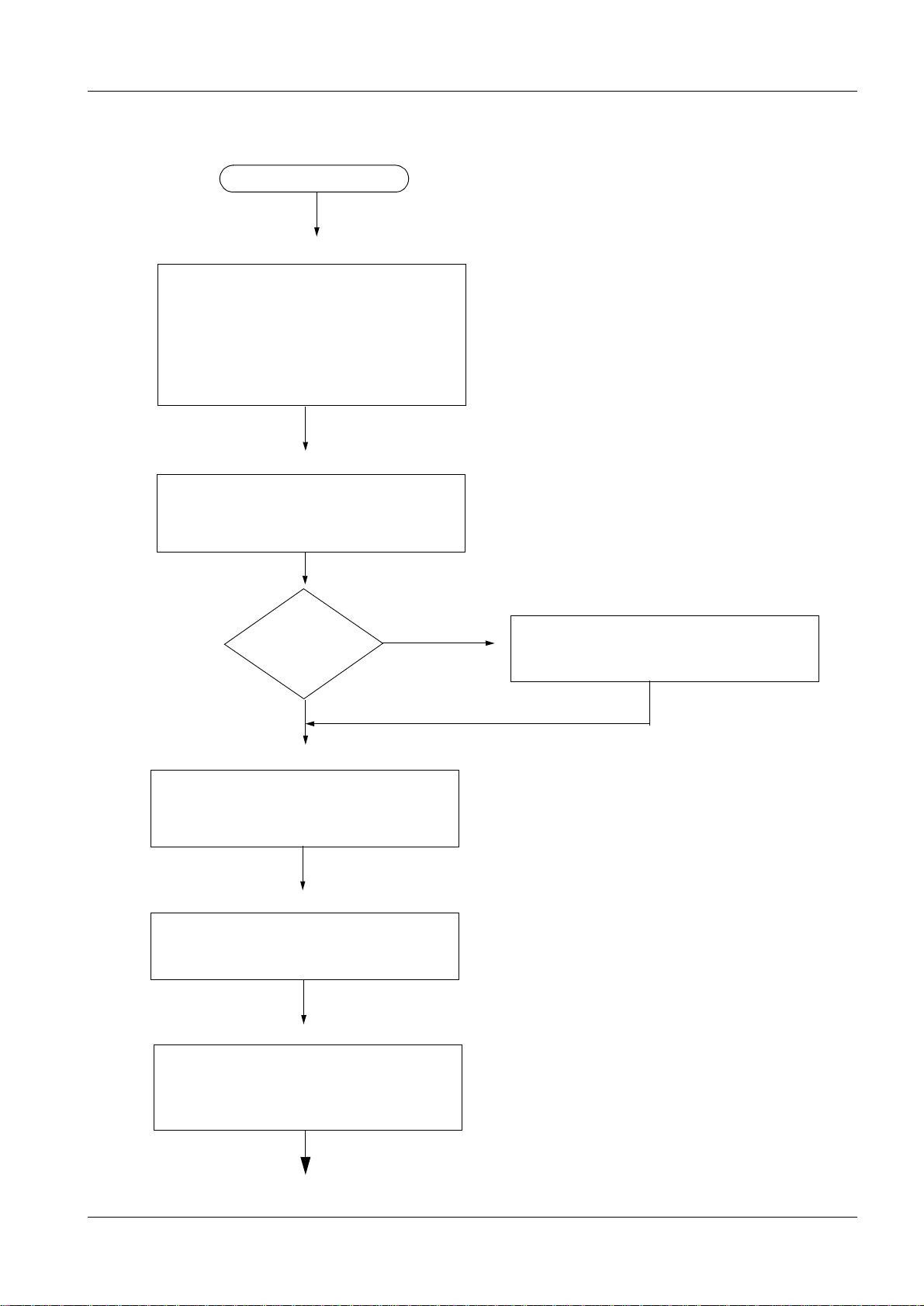
Start -up sequenc e 1
Start o f start-up
Chapter 1 Introduction
- Safety information
- Documents required
- Tools, meters and appliances
- Prerequisites
- Important notes
- Abbreviations
Chapter 2 Start-up of the acquisition workstation
- Software installation
- Software configuration
- Install service images
- Configure barcode scanner
Chapter 3 Installation and start-up of the image reade
Image reader in-
stalled by Fuji?
Yes
Chapter 4 Start-up of the viewing station (option)
- Start-up
- Software configuration
Chapter 5 Start-up of the hardcopy camera
- Hardcopy camera (recommendation)
Chapter 6 Function check
No
- Installation and start-up
- Configuration
- Screen saver timer setting
- Acquisition workstation
- Viewing station
Siemens-Elema AB Register 4 SPB7-420.815.01 Page 5 of 8 DIGISCAN M
Solna, Sweden Rev. 04 11.02 SPS-UD System Manual
Page 12
1 - 6 Introduction
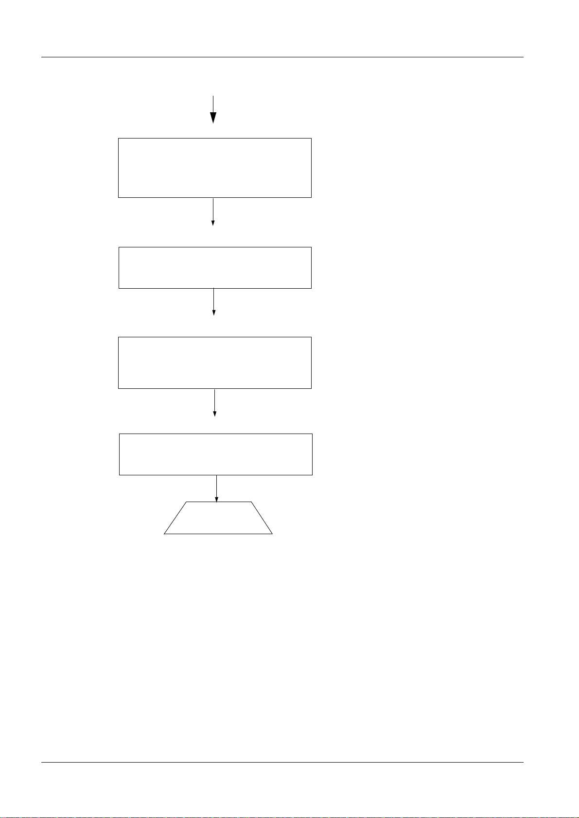
Chapter 7 AEC settings
- Backup of existing system
- Configuration of the AEC
- Testing
- Final procedures
Chapter 8 Image quality
- Acceptance test
Chapter 9 Final work steps
- Safety measurements
- Remaining work steps
- Complete protocol
Chapter 10 Turning the system over to the customer
- Customer adaptations
End of start-up
DIGISCAN M Register 4 SPB7-420.815.01 Page 6 of 8 Siemens-Elema AB
System Manual Rev. 04 11.02 SPS-UD Solna, Sweden
Page 13

Introduction 1 - 7
Abbreviations 1
AWS Acquisition Workstation
ASCRx Acquisition workstation software based on syngor
(x is product versi on)
FCR F
IVK I
IP I
IQ I
LUT L
MOD M
FCR 5000MA plus Fuji designation for the image reader
SCSI S
uji Computer Radiography
nstalled Volume Component
maging Plate
mage Quality
ookup Table
agneto Optical Disc
mall Computer System Interface
syngo is a registered trademark of Siemens AG.
Siemens-Elema AB Register 4 SPB7-420.815.01 Page 7 of 8 DIGISCAN M
Solna, Sweden Rev. 04 11.02 SPS-UD System Manual
Page 14

1 - 8 Introduction
This page intentionally left blank.
DIGISCAN M Register 4 SPB7-420.815.01 Page 8 of 8 Siemens-Elema AB
System Manual Rev. 04 11.02 SPS-UD Solna, Sweden
Page 15

Start-up of the acquisition workstation 2
General remar k 2
The DIGISCAN M system components must have been ins tal led according to
DIGISCAN M Installation Instructions, SPB7-420.812.01... .
Start-up procedure 2
Install and configure the software according to DIGISCAN M Software acquisition work-
station, SPB7-420.816.01... .
Install service images 2
Install the service images shall be used during image quality tests.
• System ON.
• Log in as meduser.
• Press the keyboard button to switch to Windo ws.
• Select Start > Programs > Accessories > Windows Explorer.
• Insert the ASCRx software CD-ROM in the CD-RW drive.
2 - 1
• Open the folder Service_Images on the CD-ROM.
• Copy all six images to C:\temp.
• Close the Windows Explorer.
• Activate the Viewing task card.
• Call up Transfer > Import from Off-line. ...
• Select C:\temp.
• Select all six “Service_Images .RF”.
• Press OK.
• Call up Patient > Browser and check that service_i mages are imported.
Siemens-Elema AB Register 4 SPB7-420.815.01 Page 1 of 6 DIGISCAN M
Solna, Sweden Rev. 04 11.02 SPS-UD System Manual
Page 16
2 - 2 Start-up of the acquisition workstation
F
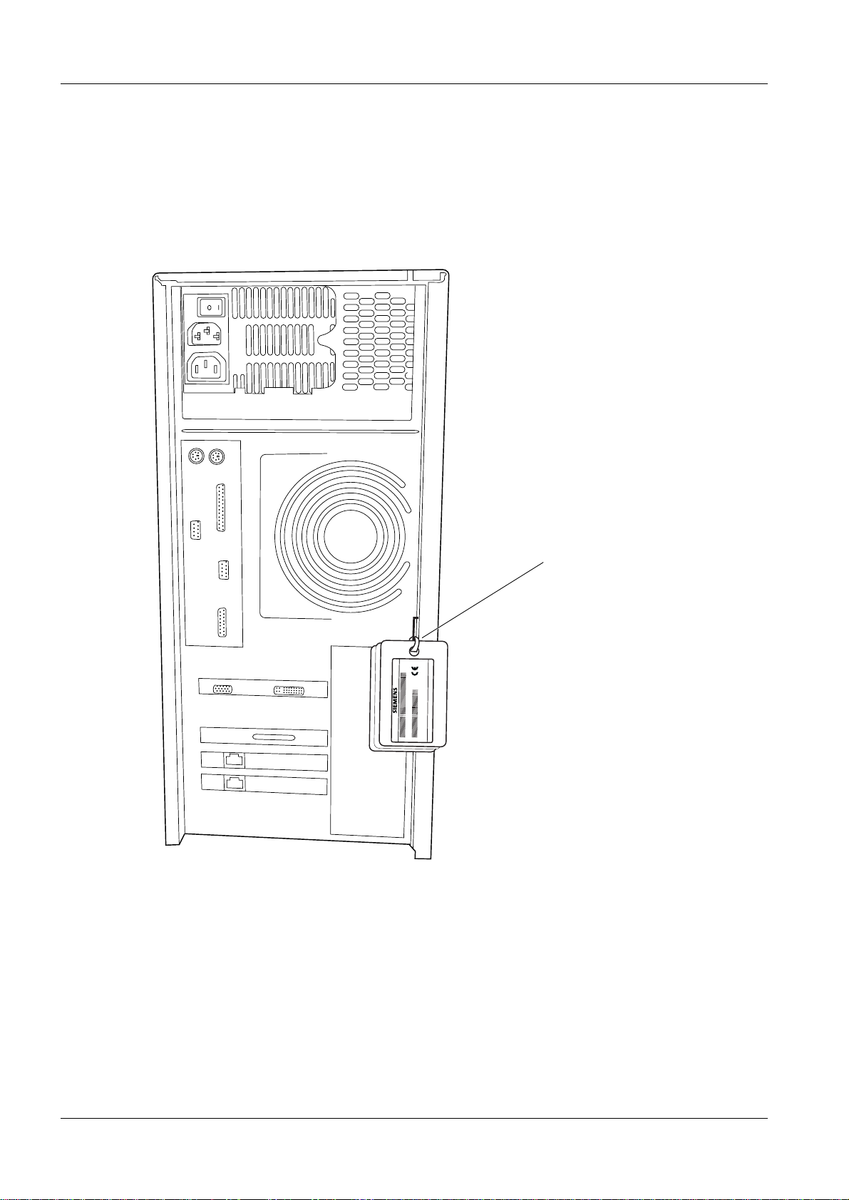
Labeling 2
Attach software version label (ASCRx), which is packed with the ASCRx software in the
installation packa ge , and syst em la bel (DI GISCAN M), which i s packed together with gray
plastic cards in the installation package, to two di fferent gray plastic cards. Fasten the
cards on the acquisition workstation with cab le t ies accor din g to Fig. 1. Attach the ac quis ition workstation label (ACQUISITION WORKSTATION), which is incl. in the acquisition
workstation package, in the same way.
Fig. 1
Fasten cable ties here
0413
Made in Sweden
Siemens-Elema AB, S171 95 Solna, Sweden
MODEL NO.:
SERIAL/LOT No.:
FDM00251
DIGISCAN M Register 4 SPB7-420.815.01 Page 2 of 6 Siemens-Elema AB
System Manual Rev. 04 11.02 SPS-UD Solna, Sweden
Page 17

Start-up of the acquisition workstation 2 - 3
Configuration of the barcode scanner 2
Sound at acquisition workstation start-up
Beeper Meaning
L L L L Parameter s loaded correctly
H H H H
long tones
Sound during barcode scanner configuration
Beeper Meaning
H H H H Correct entry or exit from configuration mode
L Good read of a command
L L L Command read error
Sound during a normal read
Beeper Meaning
L Correct read of a code in normal mode
H= high tone
L= low tone
Parameter loading error, reading or writing error in the non v olatile memory
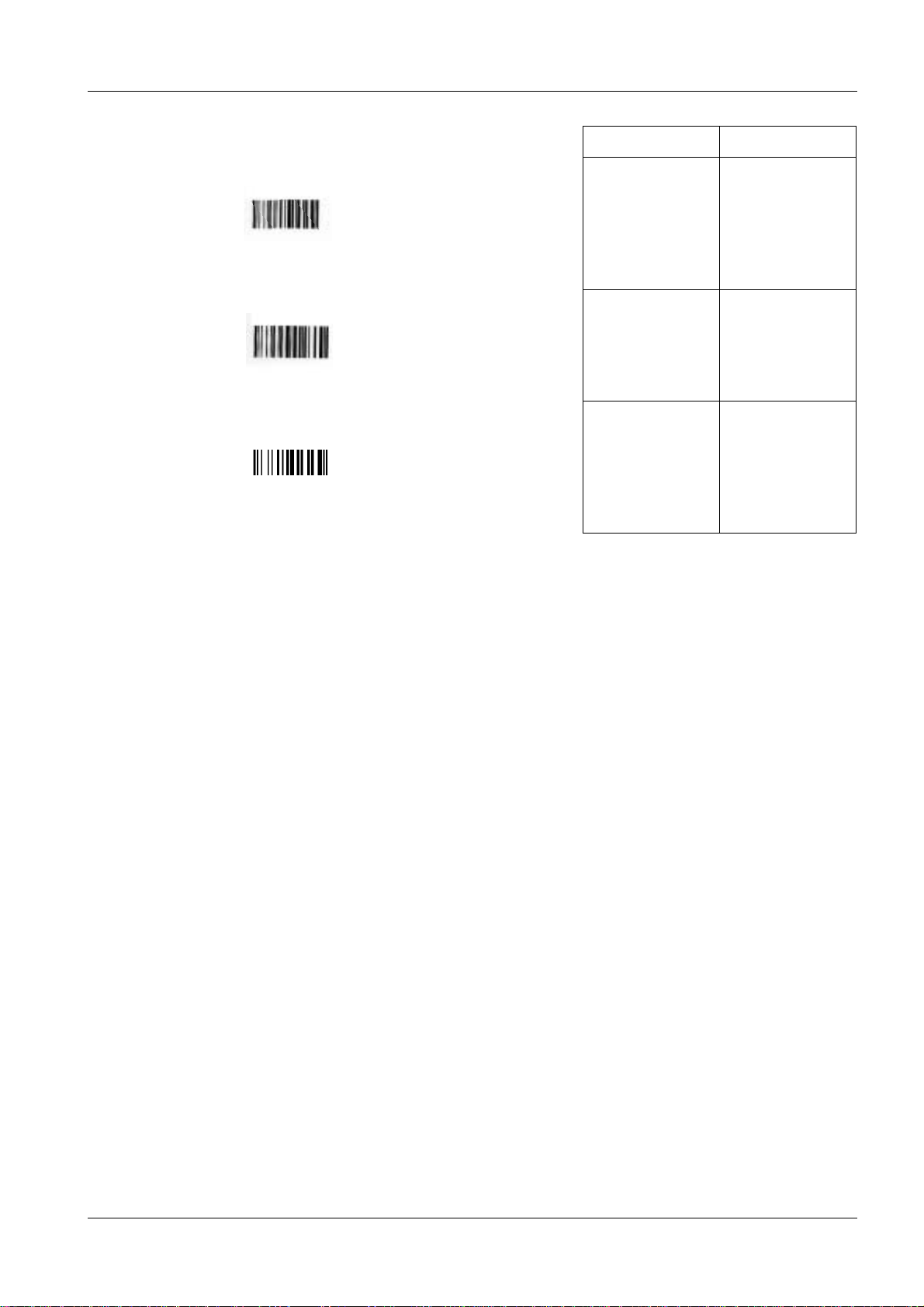
• Switch the acquisition workstation ON.
• Read the barcodes below to configure the barcode scanner. Conf irm by listening to the
sound.
NOTE
If problem occur during barcode scanner configuration, restart
with “Exit and save” and then “Restore default”.
Siemens-Elema AB Register 4 SPB7-420.815.01 Page 3 of 6 DIGISCAN M
Solna, Sweden Rev. 04 11.02 SPS-UD System Manual
Page 18
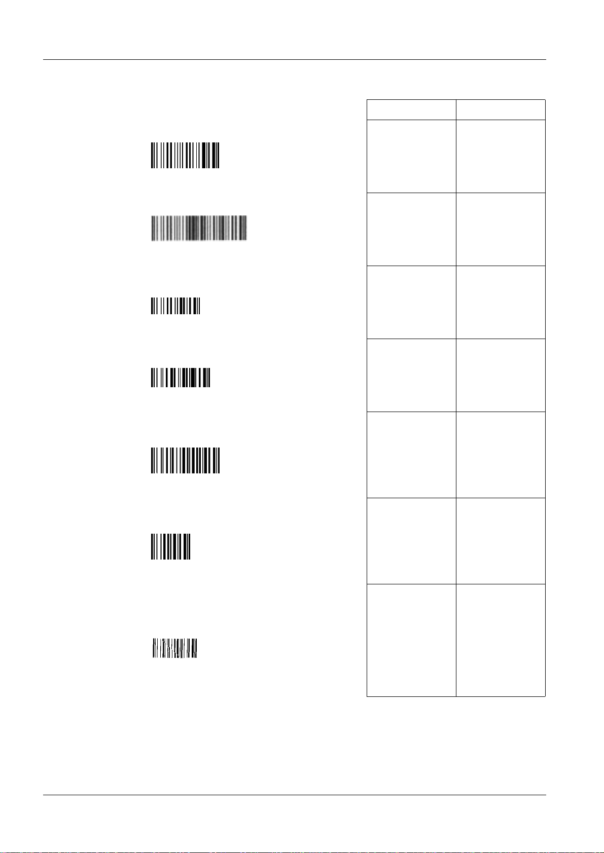
2 - 4 Start-up of the acquisition workstation
Scanner sound Decoder sound
1. Restore default HHHH HHHH
2. RS232 HHHH HHHH
3. Enter configuration (for scanner) HHHH
4. Disable all code families L
5. Codabar with no start stop character
equality check
6. No transmission of start and
stop characters
7. Increased decoding safety by forcing
the scanner to decode the barcode
three times before accepting the barcode
L
L
L
DIGISCAN M Register 4 SPB7-420.815.01 Page 4 of 6 Siemens-Elema AB
System Manual Rev. 04 11.02 SPS-UD Solna, Sweden
Page 19
Start-up of the acquisition workstation 2 - 5
Scanner sound Decoder sound
8. Active level L
9. Hardware trigger L
10. Exit and save (scanner settings) L HHHH
• Configuration complete.
Siemens-Elema AB Register 4 SPB7-420.815.01 Page 5 of 6 DIGISCAN M
Solna, Sweden Rev. 04 11.02 SPS-UD System Manual
Page 20

2 - 6 Start-up of the acquisition workstation
This page intentionally left blank.
DIGISCAN M Register 4 SPB7-420.815.01 Page 6 of 6 Siemens-Elema AB
System Manual Rev. 04 11.02 SPS-UD Solna, Sweden
Page 21
Installation and start-up of the image reader 3
Installation and start-up 3
Install and start-up the image reader accordi ng to the table below:
3 - 1
Installation
procedure
Fuji Service Manual
FCR 5000MA plus, 009.058...
DIGISCAN M Start-up
(this document)
chapter Installation
1. Chapter 1 - 20
2. "DICOM installation" on Page 3 - 3.
3. "Setting the configuration" on Page 3 - 4
4. "Backup" on Page 3 - 8
5. Chapter 23 - 27
CAUTION
The light-collecting guide assemblies are easi ly damaged.
Handle the light-collecting guide assemblies with extreme care
and use the gloves of cotton.
Starting the M-Utility (three scenarios) 3
NOTE
Instructions how to start the M-Utility is given below. Follow this
procedure when the installati on and start-up instructions requires
that the M-Utility is started.
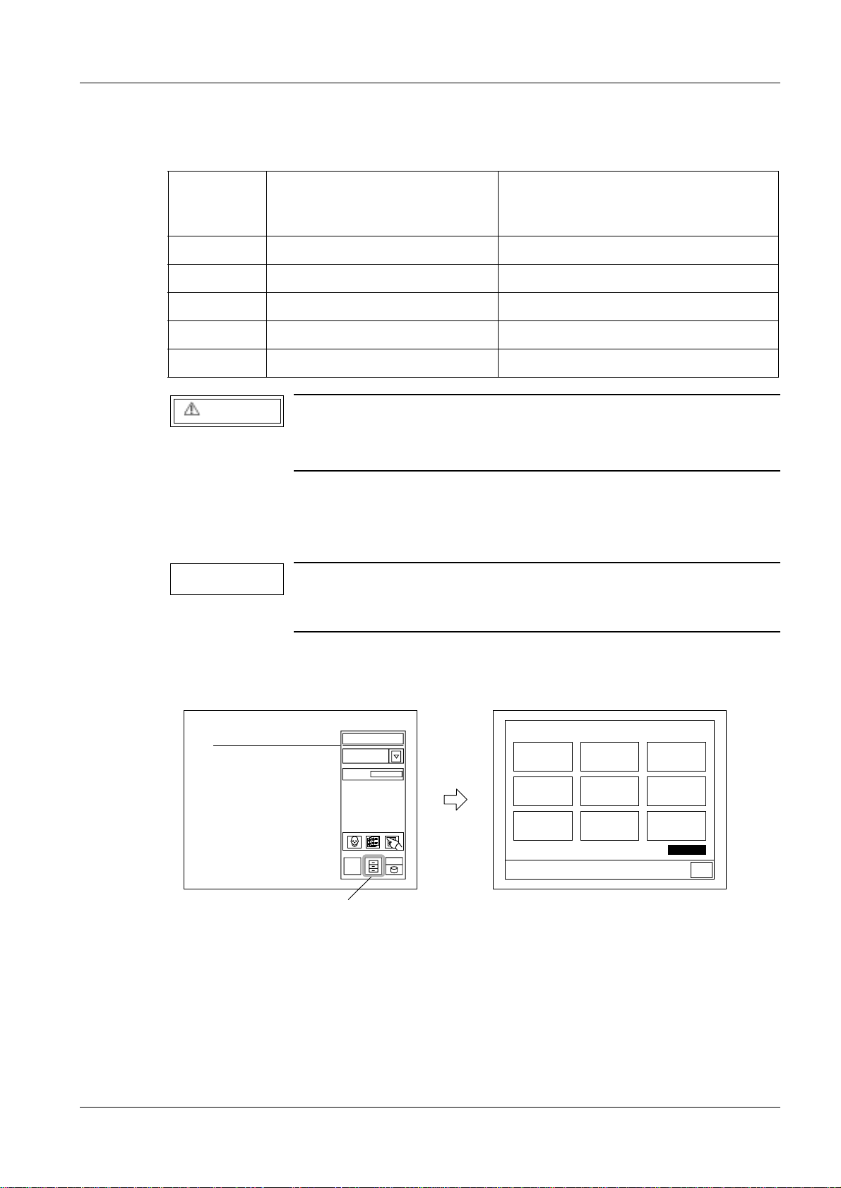
Starting the M-Utility from the routine process mode (routine mode) 3
• Press the U-Utility button.
U-Utility button
Read
Deleting images
waiting for
processing
Click sound
CRT test pattern
display
0
Processed image
reproduction
output
Touch panel
parallax correction
OUTPUT MULTI-
FRAME IMAGE
Utility
Date/time setup
Printer selection
FD operation
XXXXXX
Return
FFDM00210
Siemens-Elema AB Register 4 SPB7-420.815.01 Page 1 of 10 DIGISCAN M
Solna, Sweden Rev. 04 11.02 SPS-UD System Manual
Page 22
3 - 2 Installation and start-up of the image reader
touch the corner.
• Touch the upper left-hand corner of the touch panel, a nd then, within two seconds, touch
the upper right-hand corner to st art the M-Utility.
Deleting images
waiting for
processing
Click sound
CRT test pattern
display
Processed image
reproduction
Touch panel
parallax correction
OUTPUT MULTI-
FRAME IMAGE
Utility
: Location to be touched
output
Date/time setup
Printer selection
FD operation
XXXXXX
Return
0. QUIT
1. ERROR LOG UTILITY
2. CONFIGURATION SETTING
3. TEST MODE
4. ELECTRICAL UTILITY
5. SCANNER UTILITY
6. MECHANICAL UTILITY
7. FILE UTILITY
8. BACKUP MEMORY
9. HV ON(OFF)
10. MENU SETTING
11. SYSTEM UTILITY
AB C
DE F
789
456
123
0.SP
DEL BS ENT
Caps
FFDM00211
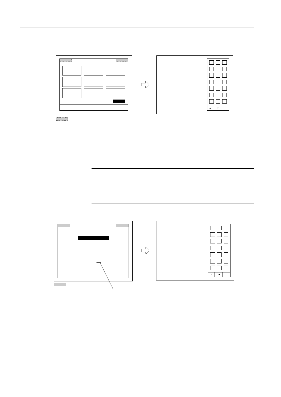
Starting the M-Utility from the initialization process mode 3
After the machine is powered ON, the initialization screen appears, and subsequently a
software version number is displayed for about five seconds. During that period of time,
touch the upper left-hand corner of the oper ati on panel, and then, wit hin t w o seconds, the
upper right-hand corner.
NOTE
After the display of the software version number ends, the operation panel does not respond at all even if y ou touch it. In such an
instance, perform a reset and wait until the software version n umber appears on the screen, or enter t he rout ine pr ocess mode and
then start the M-Utility.
Copyright (c) 2000 Fuji Photo Film Co.,Ltd
Software ID
Software Version
: Location to be touched
C R - I R 3 4 7
: 114Y5437003
: A00
Software version number
1. ERROR LOG UTILITY
2. CONFIGURATION SETTING
3. ELECTRICAL UTILITY
4. SCANNER UTILITY
5. MECHANICAL UTILITY
6. FILE UTILITY
7. BACKUP MEMORY
8. HV ON(OFF)
9. MENU SETTING
10. SYSTEM UTILITY
AB C
DE F
789
456
123
0.SP
DEL BS ENT
Caps
FFDM00233
DIGISCAN M Register 4 SPB7-420.815.01 Page 2 of 10 Siemens-Elema AB
System Manual Rev. 04 11.02 SPS-UD Solna, Sweden
Page 23
Installation and start-up of the image reader 3 - 3
FFDM00234
1. ERROR LOG UTILITY
2. CONFIGURATION SETTING
3. ELECTRICAL UTILITY
4. SCANNER UTILITY
5. MECHANICAL UTILITY
6. FILE UTILITY
7. BACKUP MEMORY
8. HV ON(OFF)
9. MENU SETTING
10. SYSTEM UTILITY
0.SP
DE F
AB C
789
456
123
DEL BS ENT
Caps
03D2
Call maintenance personnel.
IP position information error.
System down
Stop alarm
: Area to be touched
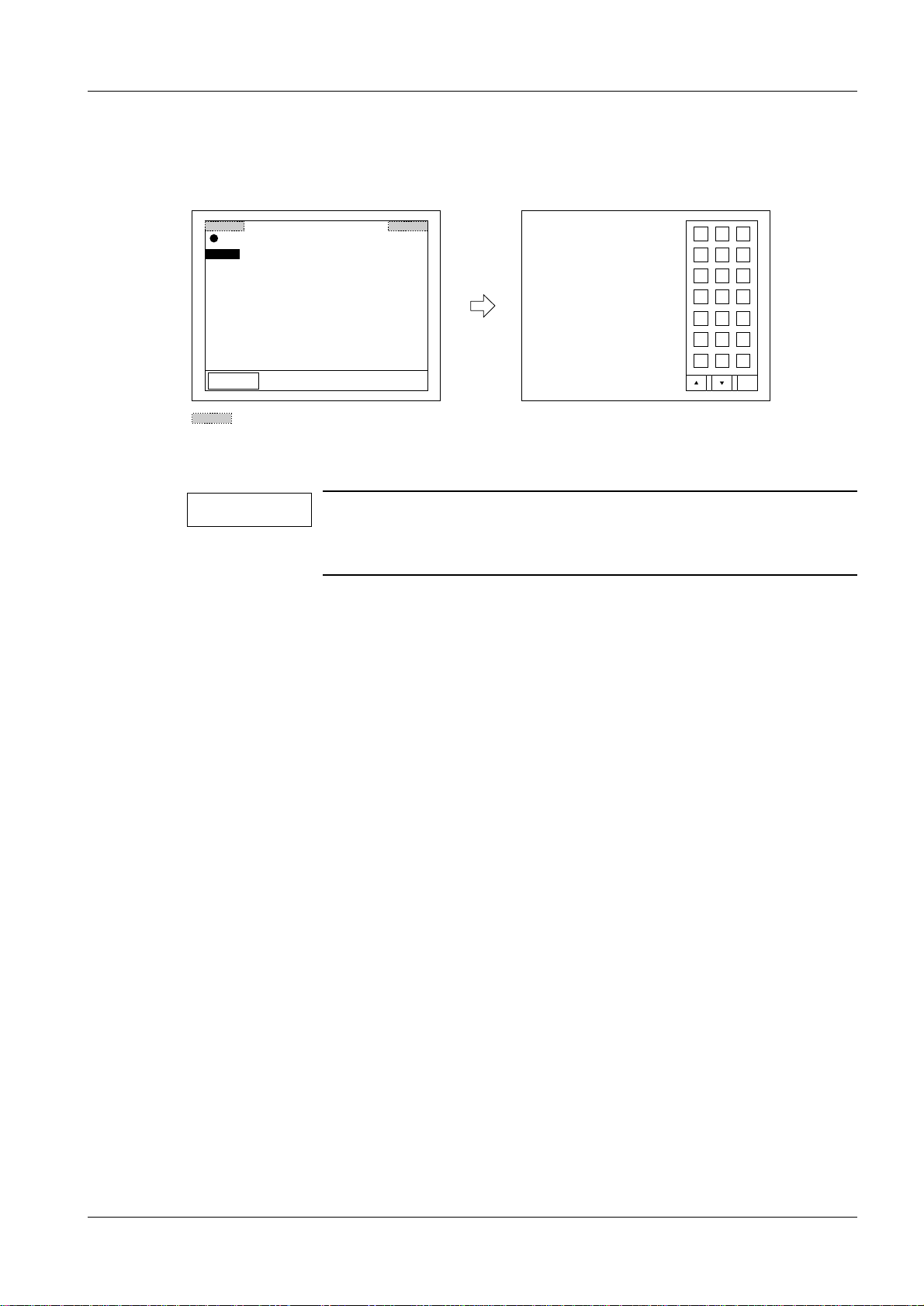
Starting the M-Utility from the abnormality process mode 3
Touch the upper left-hand corner of the operation panel, and then, within two seconds,
touch the upper right-hand corner.
Exiting M-Utility 3
NOTE
If M-Utility is entered during the initi aliza ti on sequence, “0. QUIT”
does not appear. Thus,
after quitting M-Utility, the machine should be reset.
• While the M-Utility main menu is displayed, select 0. QUIT.
• Press the reset button.
DICOM installation 3
• Start the M-Utility.
• Select [7][ENT] for FILE UTILITY.
• Put the DICOM for OEM floppy disk into the floppy disk drive.
• Select [7][ENT] for EXECUTION.
• Select [2][ENT] for INSTALL.
• Select [1][
• When the installation is finished, touch [0][ ENT].
• Touch [0][ENT].
• Touch [QUIT].
ENT] to accept that selected file is executed.
€
Siemens-Elema AB Register 4 SPB7-420.815.01 Page 3 of 10 DIGISCAN M
Solna, Sweden Rev. 04 11.02 SPS-UD System Manual
• Remove the floppy disk from the floppy disk drive.
• Turn OFF the system power switch and back ON.
• Touch [OK] when the message appears:
“The following settings have been added/delet ed. Press OK key. “
Page 24
3 - 4 Installation and start-up of the image reader
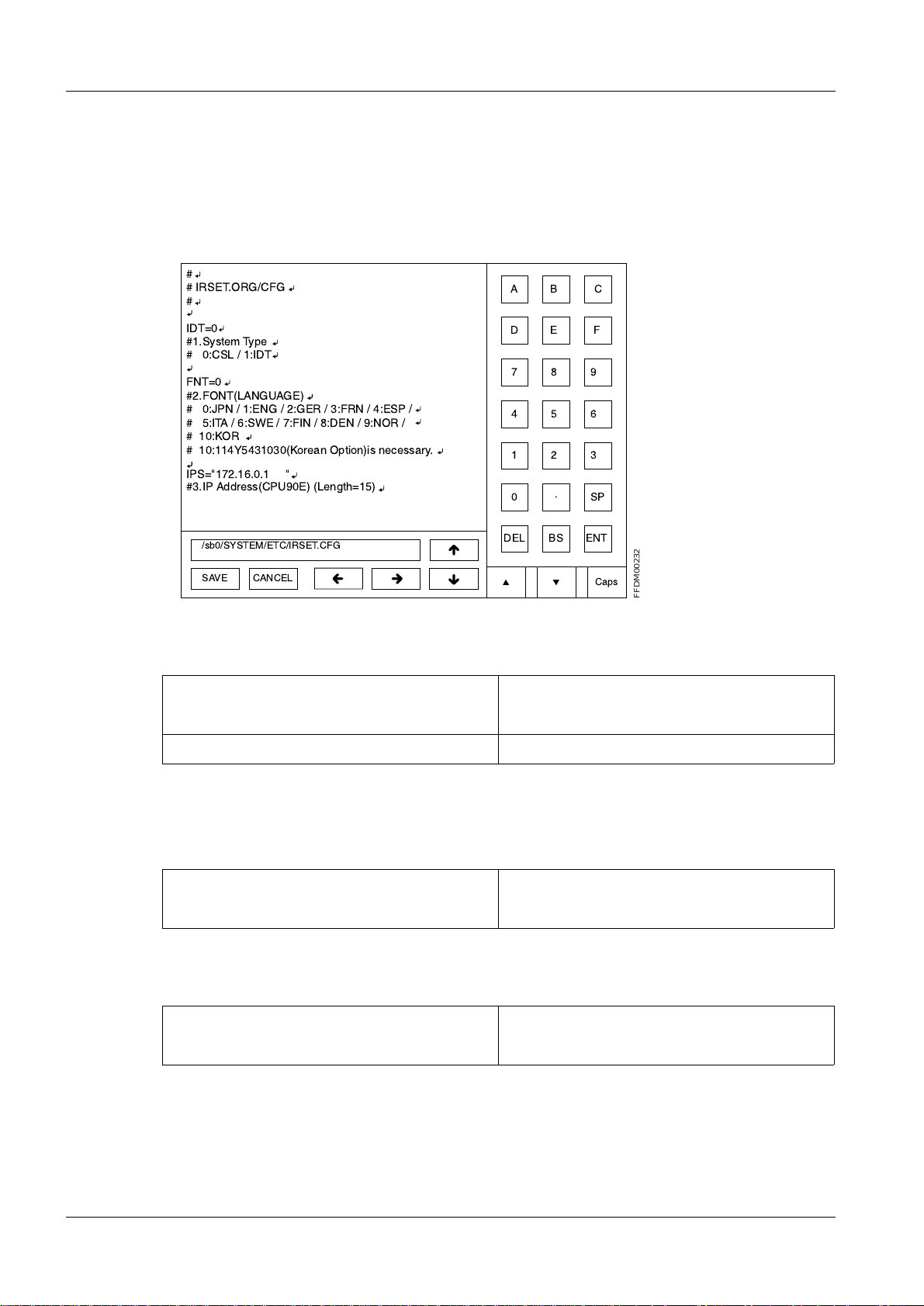
Setting the configuration 3
• Start the M-Utility.
• Select [2][ENT] for CONFIGURATION SETTING.
• Select [1][ENT] for SYSTEM.
To move the cursor, use the arrow keys or touc h the screen.
#
# IRSET.ORG/CFG
#
AB C
IDT=0
#1.System Type
# 0:CSL / 1:IDT
FNT=0
#2.FONT(LANGUAGE)
# 0:JPN / 1:ENG / 2:GER / 3:FRN / 4:ESP /
# 5:ITA / 6:SWE / 7:FIN / 8:DEN / 9:NOR /
# 10:KOR
# 10:114Y5431030(Korean Option)is necessary.
IPS="172.16.0.1 "
#3.IP Address(CPU90E) (Length=15)
/sb0/SYSTEM/ETC/IRSET.CFG
SAVE
CANCEL
DE F
789
456
123
.
0
DEL
SP
BS ENT
Caps
• Set system type to IDT:
Old New
IDT=0↵ IDT=1↵
#1.System Type↵ #1.System Type↵
#0:CSL / 1:IDT↵ #0:CSL / 1:IDT↵
FFDM00232
• Set font (language) to match the syngor installation:
For english use the fo llowing settings:
Old New
FNT=0↵ FNT=1↵
#2.FONT (LANGUAGE)↵ #2.FONT (LANGUAGE)↵
For german use the following settings:
Old New
FNT=0↵ FNT=2↵
#2.FONT (LANGUAGE)↵ #2.FONT (LANGUAGE)↵
DIGISCAN M Register 4 SPB7-420.815.01 Page 4 of 10 Siemens-Elema AB
System Manual Rev. 04 11.02 SPS-UD Solna, Sweden
Page 25

Installation and start-up of the image reader 3 - 5
For french use the following settings:
Old New
FNT=0↵ FNT=3↵
#2.FONT (LANGUAGE)↵ #2.FONT (LANGUAGE)↵
For spanish use the following settings:
Old New
FNT=0↵ FNT=4↵
#2.FONT (LANGUAGE)↵ #2.FONT (LANGUAGE)↵
• Replace the IP address of the CPU90F board (Item No. 4):
Old New
IPI=”172.16.0.2 “↵ IPI=”192.168.1.100 “↵
#4.IPAddress(CPU90F)(Length=15)↵ #4.IPAddress(CPU90F)(Length=15)↵
NOTE
Make sure that the length of the IP address is 15, i.e.
IPI=”192.168.1.100xx” where x is empty space.
• Change the screen saver setting time from 5 minutes to 1 minute (Ite m No. 14):
Old New
SSI=5↵ SSI=1↵
#14. Screen Saver Timer↵ #14. Screen Saver Timer↵
#0-60 [min]↵ #0-60 [min]↵
• Enable the distribution code:
Old New
ID_DST=0↵ ID_DST=1↵
#44. Distribution Code Setting↵ #44. Distribution Code Setting↵
#0:DISABLE / 1:ENABLE↵ #0:DISABLE / 1:ENABLE↵
• Touch [SAVE].
Siemens-Elema AB Register 4 SPB7-420.815.01 Page 5 of 10 DIGISCAN M
Solna, Sweden Rev. 04 11.02 SPS-UD System Manual
Page 26

3 - 6 Installation and start-up of the image reader
• Select [4][ENT] for EQUIPMENT.
• Replace iip with AWS:
Old New
IDT iip↵ IDT AWS↵
and type # in front of DISPLAY to disable t hat function.
• Touch [SAVE].
• Select [6][ENT] for NETWORK HOST INTERFACE (DEVICE).
• Replace:
Old New
iip:DISPLAY,0200,,,↵ AWS:DISPLAY,0200,,,2↵
• Touch [SAVE].
• Select [7][ENT] for HOST ADRESSES (HOSTS).
• Replace:
Old New
172.16.0.2 fcr5000-n↵ 192.168.1.100 fcr5000-n↵
172.16.1.20 iip↵ 192.168.1.1 AWS↵
• Touch [SAVE].
• Select [8][ENT] for DISTRIBUTION (CODEDSTB).
• Add:
Old New
#Code Host Name [HostName]...↵ #Code Host Name [HostName]...↵
00000001 AWS↵
• Touch [SAVE].
• Select [10][ENT] for NETMASKS (NETMASKS).
• Add:
Old New
172.16.0.0 255.255.0.0↵ 172.16.0.0 255.255.0.0↵
192.168.1.0 255.255.255.0↵
• Touch [SAVE].
DIGISCAN M Register 4 SPB7-420.815.01 Page 6 of 10 Siemens-Elema AB
System Manual Rev. 04 11.02 SPS-UD Solna, Sweden
Page 27

Installation and start-up of the image reader 3 - 7
• Select [11][ENT] for DICOM (Base on DICOM).
• Replace:
Old
fcr5000-n,STORAGE_U:DICOM_IR,,1,1,100,600,2↵
iip,STORAGE_P:DICOM_IIP,21760,1,1,100,600,2↵
New
fcr5000-n,STORAGE_U:DICOM_DPR,,2,0,100,600,2↵
AWS,STORAGE_P:DICOM_HIC,21760,2,0,100,600,2↵
NOTE
Make sure that the settings are correct.
• Touch [SAVE].
• Touch [0][ENT].
• Touch [0][ENT].
• Touch [QUIT].
• Turn OFF the system power switch and back ON.
Siemens-Elema AB Register 4 SPB7-420.815.01 Page 7 of 10 DIGISCAN M
Solna, Sweden Rev. 04 11.02 SPS-UD System Manual
Page 28

3 - 8 Installation and start-up of the image reader
PLEASE SET A FD.
ARE YOU SURE TO COPY SCANNER DATA FILES TO THE FD ?
1.YES 2.NO (DEFAULT=2) :
<When the FD is full>
<When there is some file that cannot be written to the FD>
Backup 3
• Start the M-Utility.
• Select [7][ENT] for FILE UTILITY.
• Select [3][ENT] for BACKUP.
• Select 1. SCANNER DATA.
FFDM00213
• Put the floppy disk into the floppy disk dri ve, and select 1.
XXXXXXXXXX IS COPIED.
XXXXXXXXXX IS COPIED.
.
.
.
XXXXXXXXXX IS COPIED.
FFDM00214
XXXXXXXXXX: Fi le name
<When the FD is full>
THE FD IS FULL. EXCHANGE OTHER ONE.
1.CONTINUE 2.CANCEL (DEFAULT=2) :
Replace the floppy disk, and select 1.
<When there is some file that cannot be writ ten to the FD>
FILE I/O ERROR. (FILE=XXXXXXXXXX)
XXXXXXXXXX: File name
• Repeat this backup procedure for:
2. CONFIGURATION DATA
3. NETWORK DATA
4. IMAGE PROCESSING DATA
5. CSL MENU DATA
6. EDR PROCESSING DATA
• Touch [0][ENT].
FFDM00215
FFDM00216
• Touch [0][ENT].
• Touch [QUIT].
• Proceed with Checking and deleting the error log duri ng setup in Fuji Service Manual
FCR 5000MA plus, 009.058... chapter Install ation.
DIGISCAN M Register 4 SPB7-420.815.01 Page 8 of 10 Siemens-Elema AB
System Manual Rev. 04 11.02 SPS-UD Solna, Sweden
Page 29

Installation and start-up of the image reader 3 - 9
Check HOSTS file 3
• Press the keyboard button to call up the Windows Start menu.
• In the Start menu select Programs > Accessories > Windows Explorer.
• In Windows Explorer right click on the file C:\WINNT\system32\drivers\etc\HOSTS
and choose Open With... from the menu.
• The Open With di alogue window opens. Choose Notepad from the list and cli ck on the
OK button.
• Check that the file contains the following line:
192.168.1.100 fcr5000-n
• If not, add the line last in the file and choos e File > Save.
• Close the file.
Siemens-Elema AB Register 4 SPB7-420.815.01 Page 9 of 10 DIGISCAN M
Solna, Sweden Rev. 04 11.02 SPS-UD System Manual
Page 30

3 - 10 Installation and start-up of the image reader
This page intentionally left blank.
DIGISCAN M Register 4 SPB7-420.815.01 Page 10 of 10 Siemens-Elema AB
System Manual Rev. 04 11.02 SPS-UD Solna, Sweden
Page 31

Start-up of the viewing station (option) 4
MagicView 1000 4
Start-up procedure 4
Start-up the viewing station according to MagicView 1000 Installation and Start-up,
P02-021.814... .
4 - 1
NOTICE
The time zone must be set up according to the country of installation to avoid image transfer problems.
Make sure that the date and time zone settings are correct.
Software configuration 4
Install the mammography user account according to DIGISCAN M Software MagicView
1000 configuration for mammography, SPB7-420.816.02... .
NOTICE
MammoReport
This can be done only by a PACS trained CSE!
Plus
Start-up procedure 4
Start-up the viewing station according to MammoReport
Instructions, SPB7-420.814.01... .
Plus
Installation and Start-up
4
Siemens-Elema AB Register 4 SPB7-420.815.01 Page 1 of 2 DIGISCAN M
Solna, Sweden Rev. 04 11.02 SPS-UD System Manual
Page 32

4 - 2 Start-up of the viewing station (option)
This page intentionally left blank.
DIGISCAN M Register 4 SPB7-420.815.01 Page 2 of 2 Siemens-Elema AB
System Manual Rev. 04 11.02 SPS-UD Solna, Sweden
Page 33

Start-up of the hardcopy camera 5
Hardcopy camera requirements 5
Recommended hardcopy cameras 5
Hardcopy cameras released for the DIGISCAN M system are listed in the document
DIGISCAN M Hardcopy Camera Information, SPB7....
5 - 1
NOTE
NOTE
The hardcopy camera must be operational.
NOTE
NOTE
Only these hardcop y cameras were tested and released. Other
hardcopy cameras may create unexpected trouble!
Requirements for optional hardcopy cameras:
That it can receive DICOM print, has a
resolution of 50x50 µm, density W3.5 and can print 18x24 and
24x30 film format.
The input for the hardcopy camera must be set to linear and maximum density by the camera manufacturer’s technician.
The function of the hardcopy c amer a is tested in "Function
check" on Page 6 - 1.
Siemens-Elema AB Register 4 SPB7-420.815.01 Page 1 of 2 DIGISCAN M
Solna, Sweden Rev. 04 11.02 SPS-UD System Manual
Page 34

5 - 2 Start-up of the hardcopy camera
This page intentionally left blank.
DIGISCAN M Register 4 SPB7-420.815.01 Page 2 of 2 Siemens-Elema AB
System Manual Rev. 04 11.02 SPS-UD Solna, Sweden
Page 35

Function check 6
6 - 1
NOTE
The acquisition workstation must be properly entered in all corresponding modalities (viewing station etc.) prior to the network
function check.
The required steps are described in the instructions for the corresponding modalities. All required informat ion regarding this can
be taken from the chapter “Data sheet and notes for connected
stations” in DIGISCAN M Software acquisit ion workstation, SPB7-
420.816.01... .
Switch on the system 6
• Switch on the image reader.
➪ Booting takes approximately 5 minutes until the utility screen will be displayed.
• Switch on the MAMMOMAT 3000 Nova.
• Switch on the viewing station (option) and start t he application.
• Switch on the hardcopy camera (recommendation).
• Switch on the acquisition workstation and login as meduser.
➪ After approximatel y 30 seconds the Examination task card will be displayed.
Function check of the acquisition workstation 6
Image transfer 6
NOTE
• Activate the Examination task card at the acquisi tion workstation.
• Register a cassette according to DIGISCAN M Instructions for use , SPB7-420.201.01...
• Click on the Patient Registration button and re gister a patient with the follo wing entries:
Last name: enter the name “Function check”.
Date of Birth: enter the current date.
Sex: select Other.
• Click on the Exam button to finish the registrat ion.
• Slide the L-cc label on the object table into t he beam path.
• Expose an 18x24 mm IP cassette in the MAMMOMAT 3000 Nova using a
4 cm plexi.
• Read barcode for exposed IP cassette.
• Read the projection view barcode L-cc.
For detailed information how to perform an examination, see
DIGISCAN M Instructions for use, SPB7-420.201.01... .
• Read the IP cassette in the image reader.
• After approximately 100 seconds, the image sho uld have arrived at the acquisit ion
workstation.
Siemens-Elema AB Register 4 SPB7-420.815.01 Page 1 of 4 DIGISCAN M
Solna, Sweden Rev. 04 11.02 SPS-UD System Manual
Page 36

6 - 2 Function check
• Click on the End of examination button to exit the examinat ion.
• Depending on the work routine of the hospital, e nsure that the image is archived on the
MOD and/or CD-R and/or sent to an archive sy stem, and sent to a viewing station
(option).
WARNING
Images can not be archived on MOD or CD-R or sent to an ar chi ve
system from the MammoReport
Images will not be saved.
Send acquired images both to an archive system and to the Mam-
moReport
Plus
from the acquisition workstation.
Plus
(option).
• Following the above-listed procedure, expose and read out another image. Use the
same patient data but slide the R-cc label into the beam path and read the projection
view barcode R-cc.
• After the last image was displayed on the acquisition wor kstation, check in the Patient
Browser that the two images have been filed in one folder.
Filming (option) 6
• Activate the Viewing task card.
• Call up Options > Configuration... > Filming Layout .
• Select the Series tab.
• Deselect Reference image.
• Under Aspec t Ratio select Keep visible part.
• Press Apply and then OK.
• Select one of the images in the Patient Browser.
DIGISCAN M Register 4 SPB7-420.815.01 Page 2 of 4 Siemens-Elema AB
System Manual Rev. 04 11.02 SPS-UD Solna, Sweden
Page 37

Function check 6 - 3
• Call up Patient > Copy to Film Sheet in the main menu or by us ing the symbol keypad.
• Switch to the Filming task card.
• In Camera t ab, select Film Size Inch 11x14.
• In Images tab, select .
• Call up Film > Expose Film Sheet.
• Check that the image is exposed in normal size and without any de formation.
Make sure that the two projection v iews displayed in the image are shown from th e same
side.
Siemens-Elema AB Register 4 SPB7-420.815.01 Page 3 of 4 DIGISCAN M
Solna, Sweden Rev. 04 11.02 SPS-UD System Manual
Page 38

6 - 4 Function check
Function check of the viewing station (option) 6
MagicView 1000 6
Image transfer
• Open the “Function check” patient.
• Check that the two images are loaded and displayed correctly on the scre ens. Make sure
that the two projection views displ ayed in the images are shown from the same side.
• Check that the text information about the patient and the study is displayed correctl y in
the images.
• If the images were not archived on MOD and/or CD-R and/or sent to archive system from
the acquisition workstation, do i t from the viewing station.
• Check that the images were archived and/or sent correct ly.
• Remove the images from the viewing station.
• Import the images from MOD, CD-R or archive system.
• Check that the images are displayed correctly .
Filming (option)
• Click on the first image to select it.
• Select the Quick print function in the Networking menu.
• Check that the image is exposed in normal size and without any deformation. Make sure
that the two projection views displ ayed in the image are shown from the same side.
MammoReport
Image transfer
Plus
• Make sure that the images also are sent from the acquis ition workstation to an archi ve.
• Open the “Function check” patient.
• Select single tiling so that one image is shown on each screen.
• Check that the two images are loaded and displayed correctly on the scre ens. Make sure
that the two projection views ar e displayed in the images.
• Check that the text information that is displa yed in the images and in the patient li st is
correct.
Filming (option)
6
• Click on the DICOM print button.
• Click in the Print left Monitor check box.
• Press the Print button.
• Check that the images are printed out correctl y.
DIGISCAN M Register 4 SPB7-420.815.01 Page 4 of 4 Siemens-Elema AB
System Manual Rev. 04 11.02 SPS-UD Solna, Sweden
Page 39

AEC settings 7
General 7
These instructions describe installation of AEC floppy disk with material No. 66 01 897.
This floppy disk makes AEC tables for Fuji CR HR-BD imaging plate in IP CASS-BD M
available.
The AEC is based on correction tables. The tables are optimized for the IP/cassette
combinations in table 1.
Table 1 Correction table identifications
Scanner IP Cassette Sensitivity Mo/Mo Mo/Rh W/Rh
7 - 1
DIGISCAN M Fuji
CR HR-BD
Fuji
IP CASS-BD M
0 1401 1402 1403
Siemens-Elema AB Register 4 SPB7-420.815.01 Page 1 of 32 Digiscan M
Solna, Sweden Rev. 04 11.02 SPS-UD System Manual
Page 40

7 - 2 AEC settings
m
A
p
Definitions 7
AD Value
D V alue
ax 1023
450
min 0
0.01 0.1 1 10
log Ex
Old backup floppy disk Backup floppy disk to store data from before the
installation. To be marked “Old backup” and with serial
No. of system, date, and version of the correction tables.
New backup floppy disk Backup floppy disk to store data during and after the
installation. To be marked “Ne w backup” and with serial
No. of system, date, and version of the correction tables.
Digiscan M Register 4 SPB7-420.815.01 Page 2 of 32 Siemens-Elema AB
System Manual Rev. 04 11.02 SPS-UD Solna, Sweden
Page 41

AEC settings 7 - 3
Protective measures 7
It is very important that any interv ention in the equipment wil l start by disconnect ing it from
the power supply with the main circuit-breaker.
WARNING
WARNING
If the system is only switched off at the control panel or with
S2/D711, line vol ta ge will still be prese nt a t the generat or l ine connection, line filter Z1, Z2, transformer T1, transformer T10 and
PC board D711 (see MAMMOMAT 3000 Nova Wiring Diagram).
Life-threatening electric shock hazard exists.
Disconnect mains cable and comply with the information on this
page.
After shut-down of the system, there may still be 380 V DC
present on the intermediate circuit.
Life-threatening electric shock hazard exists.
The voltage level will be indicated by LED V24 on PC board D710.
The voltage will dr op to less than 30 V withi n about 3 minutes, the
LED goes out at about 30 V.
Symbols 7
Checks and adjustments that m ust be perf ormed with radi ation ON are i dentif ie d
by the radiation w a rning symbol.
Delay times between two exposures 7
Delay times listed below must be followed in or der to prevent the tube from overheating.
Exposure mAs value Delay time between two e xposures (seconds)
max 100 min 15
max 200 min 30
max 300 min 45
max 400 min 60
max 500 min 75
Siemens-Elema AB Register 4 SPB7-420.815.01 Page 3 of 32 Digiscan M
Solna, Sweden Rev. 04 11.02 SPS-UD System Manual
Page 42

7 - 4 AEC settings
Preparation 7
1. System ON.
2. Login as meduser.
3. Open Windows Explorer.
4. Create a new folder under drive D: and name it “AEC_i nst”.
5. Insert the service program floppy i n drive A:.
6. Copy the files service.exe and m3000.h60 fr om A: to AEC_inst.
7. Insert the floppy AEC correction tabl es in drive A:.
8. Copy the AEC correction tables from A: to AEC_inst.
9. Mark an empty backup floppy with new backup, s erial number of system, version
of the correction tables, and d ate. Insert the floppy in dri ve A.
10. Copy the content of AEC_inst to A:.
Use this floppy for the rest of the i nstallation.
11. If AEC correction tables have been install ed on the MAMMOMAT before, make a
backup of these tables, see "Backup of ex isting system" on Page 7 - 6.
12. Select Options > Service > Local Service in the window menu header.
13. Enter the service key (6 chara cters in 2nd mask).
14. Confirm the screen with OK. The Service Home menu appears.
Digiscan M Register 4 SPB7-420.815.01 Page 4 of 32 Siemens-Elema AB
System Manual Rev. 04 11.02 SPS-UD Solna, Sweden
Page 43

AEC settings 7 - 5
15. Select Quality Assurance.
16. In Source select AEC Calibration.
17. In AEC Calibration select Enable calibration mode.
18. Select Go in the action bar.
19. Minimize the Quality Assurance window.
20. Press Start and select Programs > Accessories > Command Prompt.
21. In the DOS prompt, type:
“A:” and press Enter,
“service” and press Enter.
22. - In the log in-menu, enter you r name and press Enter.
- Type the password for the service pr ogram and press Enter.
- In Program-mode set: normal.
23. Proceed with "Definiti ons" on Page 7 - 8.
Siemens-Elema AB Register 4 SPB7-420.815.01 Page 5 of 32 Digiscan M
Solna, Sweden Rev. 04 11.02 SPS-UD System Manual
Page 44

7 - 6 AEC settings
Backup of existing system 7
1. Press Start and select Programs > Accessories > Command Prompt.
2. In the DOS prompt, type:
“CD \” and press Enter,
“MKDIR mammomat” and press Enter,
“CD mammomat” and press Enter,
“A:” and press Enter.
3. Make sure that the service fl oppy is still in drive A:.
4. Start the service program by writi ng: Service , then press Enter.
5. - In the log in-menu, enter your name and pr ess Enter.
- Type the password for the service progra m and press Enter.
- In Program-mode set: normal.
6. Check that service program version 4. 3 or higher is used. The version is shown in
the top left corner of th e display.
7. In Mainmenu select Configuration > Power. Note the d isplayed power values in
the test protocol on Page 11 - 1.
8. Take the backup to hard disk: Backup > Copy insta llation area to disk > All.
9. Take out the floppy with the service pro gram and insert an empty floppy disk and
mark it with old backup, serial number of system, version of the cor rection tables,
and date. This floppy is defined as old backu p floppy.
10. In Mainmenu select Configuration > Save config file. Press F2 to save.
11. In Mainmenu select Service > Copy erro r buffer to file.
12. If the MAMMOMAT is equipped with OPDOSE, press the left program button on
the panel. Note the display ed exposure settings in the test prot ocol on Page 11 - 1.
Repeat for all four programs. Enter menu Conf iguration > Miscellaneous >
Auto limits. Note the three values i n test protocol on Page 11 - 1, in column
“Breast thickness”.
13. Quit the service program by pres sing F10.
14. Type “C:”.
15. Type “COPY *.TXT A:”.
Digiscan M Register 4 SPB7-420.815.01 Page 6 of 32 Siemens-Elema AB
System Manual Rev. 04 11.02 SPS-UD Solna, Sweden
Page 45

AEC settings 7 - 7
16. Check that the following backu p files are stored on the floppy disk (b y typing
“dir a:”, then pressing Enter):
- a_backup.txt for AEC parameters
- s_backup.txt for stand parameter s
- p_backup.txt for panel parameter s
- momo_h.txt for AEC correction tables
- morh_h.txt for AEC correction tabl es
- wrh_h.txt for AEC correction tabl es
- momo_d.txt for AEC correction tables
- morh_d.txt for AEC correction tabl es
- wrh_d.txt for AEC correction tabl es
- mammo.cfg for configuration parameters
- errorbuf.txt for err or log
17. Type “DEL *.TXT”.
18. Remove the floppy disk and make it write pr otected.
Siemens-Elema AB Register 4 SPB7-420.815.01 Page 7 of 32 Digiscan M
Solna, Sweden Rev. 04 11.02 SPS-UD System Manual
Page 46

7 - 8 AEC settings
Definitions 7
Object table group 7
An object table group contai ns all object tab les of the same type. There are four groups of
object tables - Grid, No grid, Magni fication and Stereo. For example the object tab le g roup
Grid, consists of Grid 18x24 and Grid 24x30.
NOTE
Stereo shall not be used together with DIGISCAN M.
General conditions 7
When performing the settings in this chapter, there are some general conditions valid for
all settings:
• The detector is to be in chest wall positi on.
MAM00616
• The AEC calibration plexi (material No. 65 61 224 and 65 61 232) must extend at leas t 10
mm beyond the chest wall edge of the table and be centere d. Place the AEC calibration
plexi in the same position for all exposures.
Calibration conditions 7
Compression plate must not be used during the calibration of corre ction tables. From the
point sensitivity correction (fine setting) a compression plate may be used.
Reference IP cassette 7
Every DIGISCAN M system should have a reference IP cassette. Use this reference IP
cassette where required and for the settings in this chapter. If there is no dedicated reference IP cassette, pick one IP cassette, mark it and use it for the settings in this chapter.
Mains voltage 7
Unless otherwise stated, the mains voltage and system must be ON and the service program running, before performing any setting in this chapter.
Sensitivity conditions 7
One step (1/8 E.P.) corresponds to approximately 4 AD Values.
Digiscan M Register 4 SPB7-420.815.01 Page 8 of 32 Siemens-Elema AB
System Manual Rev. 04 11.02 SPS-UD Solna, Sweden
Page 47

AEC settings 7 - 9
Overview of work routine 7
Main menu
Configuration
Service
Normal mode
Test DUEP Communic.
Backup
Quit
Configuration
System type
Anode
Show configuration file
Save configuration file
AEC
Miscellaneous
Filament
AEC
Reset installation parameters
Detector normalization
AEC Correction tables
Sensitivity correction
Copy H to D
Copy D to H
Sensitivity
MAM00611
1. "AEC Correction tables" on Page 7 - 11.
2. "Sensitivity correcti on (fine setting)" on Page 7 - 21.
3. "Sensitivity" on Page 7 - 25.
Siemens-Elema AB Register 4 SPB7-420.815.01 Page 9 of 32 Digiscan M
Solna, Sweden Rev. 04 11.02 SPS-UD System Manual
Page 48

7 - 10 AEC settings
DLF switch off 7
Deactivate the DLF switch. In Main menu select Configuration > Miscellaneous > DLF
switch, press space to set switch to OFF. Press F2 to save.
Cassette loaded 7
In Mainmenu select Configuration > Miscellaneous > Cassette loaded check. Set to
OFF during the whole installation.
Increase grid speed 7
Increase the grid speed. In Main menu select Configuration > Grid speed. Set the fol-
lowing values:
Grid
Grid fast speed time 1500
Grid fast speed 90
Grid slow speed 30
<ESC> to exit, <TAB> move to next entry field
1 Help 2 Save 3 45678910Quit
ms (2.5 s max)
% of max
% of max
MAM00761
Digiscan M Register 4 SPB7-420.815.01 Page 10 of 32 Siemens-Elema AB
System Manual Rev. 04 11.02 SPS-UD Solna, Sweden
Page 49

AEC settings 7 - 11
AEC correction tab
AEC Correction tables 7
This section will guide you through the following steps:
• Installation of correction tables ( F2).
• Calibration of correction tables (F3), including rough setting of sensitivity correction.
The AEC uses one correction table for each Anode/Filter/Speed combination. Each correction table has separ ate corrections for eac h object tabl e group (Magnifi cation, Grid and
No grid).
Installation of AEC correction tables 7
1. In Mainm enu select Configuration > AEC > AEC correction tables.
The dashes in the ID column show that no correct ion table is installed (
Fig. 1
).
AEC correction tab
Existing tables in the AEC:
Anode/Filter Speed ID Calibrated
Mo/Mo H ---- --- --- --- --Mo/Mo D ---- --- --- --- --Mo/Rh H ---- --- --- --- --Mo/Rh D ---- --- --- --- --W/Rh H ---- --- --- --- --W/Rh D ---- --- --- --- ---
<ESC> to exit, <F2> to install new table, <F3> to calibrate existing
1 Help 2 Inst Cal3 45678910Quit
Fig. 1 AEC correction tables
NOTE
Install the correction tables on D only!
les
Mag Grid No grid Stereo
MAM00599
Siemens-Elema AB Register 4 SPB7-420.815.01 Page 11 of 32 Digiscan M
Solna, Sweden Rev. 04 11.02 SPS-UD System Manual
2. Make sure that the new backup floppy is in serted.
3. Decide for which combination you need to inst all correction table. (F or av ailable
identifications for correc tion tables see Table 1, Page 7 - 1 or the new back up
floppy.)
Page 50

7 - 12 AEC settings
4. Place the cursor by one of the desired Anod e/Filter/Speed combinations. Press
F2.
Install new table
New ID: 0000
<F2> to continue, <ESC> to exit
MAM00600
5. Type the ID number of the new correction table ( see Table 1, Page 7 - 1) in the
dialog which appears. Press F2 to ins tall the table. A message box will appear
before the correction file has been f ound.
Searching for correction file...
MAM00736
Installing correction table
ID: 1401 for Mo/Mo D
29% done
MAM00880
6. When the transaction of tables is finished, a dialog like Fig. 2, Pag e 7 - 14 will
appear. To complete the calibr ation, proceed from step 5 of that se ction.
NOTICE
In order to resume calibrati ng aft e r having quit the program:
Follow the instructions from step 1 under "Calibrate correction
tables" on Page 7 - 13.
Digiscan M Register 4 SPB7-420.815.01 Page 12 of 32 Siemens-Elema AB
System Manual Rev. 04 11.02 SPS-UD Solna, Sweden
Page 51

AEC settings 7 - 13
AEC correction tab
Calibrate correction tables 7
NOTE
The new backup floppy must be inserted.
The Anode/Filter/Speed combinations should be cali brated one at a time.
1. In Mainm enu select Configuration > AEC > AEC correction tables.
AEC correction tab
Existing tables in the AEC:
Anode/Filter Speed ID Calibrated
Mo/Mo H ---- --- --- --- --Mo/Mo D 1401 No No No No
Mo/Rh H ---- --- --- --- --Mo/Rh D 1402 No No No No
W/Rh H ---- --- --- --- --W/Rh D 1403 No No No No
<ESC> to exit, <F2> to install new table, <F3> to calibrate existing
1 Help 2 Inst Cal3 45678910Quit
les
Mag Grid No grid Stereo
MAM00881
NOTICE
All object table groups and Anode / Filter combinations available
at the site must be calibrated prior to release for clinical use.
2. Place the marker by one of the desired Anode/Fil ter/Speed combinations. Press
F3 to transfer the table.
3. This message box is displayed while the serv ice program receives the correction
table.
Receiving correction table
for Mo/Mo D
63% done
MAM00882
Siemens-Elema AB Register 4 SPB7-420.815.01 Page 13 of 32 Digiscan M
Solna, Sweden Rev. 04 11.02 SPS-UD System Manual
Page 52

7 - 14 AEC settings
4. When the transfer is done, the dialog Calibr ation AEC correction table appears.
Calibration AEC correction table
Mo/Mo D, Table ID: 1401
Object table group
Magnification Not calibrated
Grid Not calibrated
No grid Not calibrated
Stereo Not calibrated
<ESC> to exit, <F2> to save, <F3> to calibrate, <F4> to clear calibration
1 Help 2 Save Cal3 45678910Quit
Fig. 2 Dialog Calibration AEC correction table shows which object tables, in the current Anode/Filter/Speed
combination, have been calibrated.
Clear
5. To calibrate the correction table for an object table group, place the cur sor in front
of the group. Press F3.
Please mount a
grid table
and press <ENTER> to continue
or <ESC> to cancel.
MAM00608
NOTE
<ENTER> - ok / <ESC> - cancel
Calibration of correction tabl es for Stereo is not included in
DIGISCAN M.
MAM00883
Digiscan M Register 4 SPB7-420.815.01 Page 14 of 32 Siemens-Elema AB
System Manual Rev. 04 11.02 SPS-UD Solna, Sweden
Page 53

AEC settings 7 - 15
6. Follow the instructions in t he message box above and press Enter.
Sensitivity correction
Used: 0
New: 0
<F2> save, <F3> exp support, <F4> continue, <ESC> exit
Fig. 3 Dialog Sensitivity correction
MAM00764
7. Before calibrating the i nstalled correction tab les, it is necess ary to make a rough
setting of the sensitivity co rrection for the chosen object tab le group .
8. Press the keyboard button to switch to the Examination task card. If the
Quality Assurance window is maximized, minimize i t.
9. Click on the Patient Registration butt on and register a patient with the fol lowing
entries:
Last name: enter the name “AEC patient”.
Date of Birth: enter the current date.
Sex: select Other.
10. Click on the Exam button to fini sh the registration.
11. Check that the AEC symbol is displayed on the Examination task card.
AEC symbol
12. Press the keyboard button and click on the Command Prompt button in the
lower taskbar to switch to the ser vice program.
Siemens-Elema AB Register 4 SPB7-420.815.01 Page 15 of 32 Digiscan M
Solna, Sweden Rev. 04 11.02 SPS-UD System Manual
Page 54

7 - 16 AEC settings
13. Insert the referenc e IP cassette in the object table.
NOTE
NOTE
Press F3.
14. Follow the instructions in the message box in the service program for pe rforming
an exposure.
15. Press Enter.
16. Press the keyboard button to switch to the Examination task card.
17. Read barcode for exposed IP cassette.
18. Read the projection view barcode L-cc.
Make sure the new backup floppy is inserted.
Do not use a compression plate.
Please put x cm of Plexi
on the object table.
Perform an exposure and
press <ENTER> when ready
or <ESC> to cancel.
<ENTER> - ok / <ESC> - cancel
MAM00728
19. Read the IP cassette in the image rea der.
20. Register the mean value (AD Value) that i s displayed on the screen and press OK.
21. If the value differs from 450, switch to the service program, adj ust the values in
dialog AEC - Sensitivity correction (Fig. 3) and save the new Sensitivit y correction
value with F2. Repeat the procedures described f rom step 6 to step 20 until the
value 450 is reached.
If the value is satisfactory, proceed by pr essing F4. Switch to the Examination task
card and click on the End of examination butt on to exit the examination.
NOTE
One adjustment step of sensitivity correction (1/8 E.P.)
corresponds to approximately 4 AD Values, i.e.
450 x–
----------------- -
y=
4
x = obtained mean value
y = suggested adjustment for sensitivity correction
Digiscan M Register 4 SPB7-420.815.01 Page 16 of 32 Siemens-Elema AB
System Manual Rev. 04 11.02 SPS-UD Solna, Sweden
Page 55

AEC settings 7 - 17
NOTE
It is important to use 450 and the specified AEC calibration plexi
(material No. 65 61 224 and 65 61 232) during the procedures
under “Calibrate correction tables”, since measurements are
relative to factory results at 450.
The AD Value preferred by the customer can be adjusted later
either in Sensitivity correction or Sensitivity.
22. Press the keyboard button and click on the Command Prompt button in the
lower taskbar to switch to the ser vice program.
23. Take another IP cassette than the r eference IP cassette. Since it will not be
developed, the IP cassette can be used for all exposures during the following
calibration.
NOTE
Using secondary erasure, erase the used IP cassette after the
fourth exposure, otherwise the IP cassette cannot be utilized for
one day.
Calibration object table group
Mo/Mo D, Table ID: 1401, Object table group Grid
Exp. Plexi kV Dose rate Diff. from nominal
1 3 25 --------- ------2 3 28 --------- ------3 4 25 --------- ------4 4 32 --------- ------5 4 35 --------- ------6 6 25 --------- ------7 7 28 --------- ------8 7 32 --------- ------9 7 35 --------- -------
<ESC> to exit, <F2> to calibrate & save, <F3> to measure dose rate
1 Help 2 Save Exp support3 4 5 6 7 8 9 10 Quit
Fig. 4 Dialog Calibration object table group shows the dose rates for a number of exposures. The dashed
lines below Dose rate indicate that no exposures have been performed yet.
MAM00885
Siemens-Elema AB Register 4 SPB7-420.815.01 Page 17 of 32 Digiscan M
Solna, Sweden Rev. 04 11.02 SPS-UD System Manual
Page 56

7 - 18 AEC settings
24. To proceed with the calibration, pl ace the cursor by one of the alternativ es. Press
F3.
Please put x cm of Plexi
on the object table.
Perform an exposure and
press <ENTER> when ready
or <ESC> to cancel.
<ENTER> - ok / <ESC> - cancel
MAM00728
25. Follow the instructions in the message box shown.
NOTE
Do not use 2 8 1 cm plexi plates instead of a 2 cm plate.
26. When the exposure is done, the dialo g Calibration exposure appears with values
for Dose rate and Diff. from nominal.
Calibration exposure
Mo/Mo D, Table ID: 1401, Object table group Grid
Exp. 5
Tension 25 kV
PMMA 4 cm
Dose rate 267.23
Diff. from nominal -21.47%
<ESC> to exit, <F2> to save, <F3> to perform exposure
1 Help 2 Save Exp support3
5678910
4
Quit
MAM00884
NOTE
If the Diff. from nominal exceeds &50% ensure that the exposure
really has taken place, the thic kness of AEC calibration plexi
(material No. 65 61 224 and 65 61 232) is correct and properly
positioned and that the cassette (loaded with IP) is inserted and
repeat the last exposure. If the difference still exceeds +50%
accept the value and proceed.
27. Save the values with F2.
28. Repeat steps 24 to 27 until all expos ures are done.
29. Perform a primary erasure of the IP cas sette according to Fuji Operating Manual
FCR5000MA plus.
30. When all exposures for one object table gro up are done, save the values with F2
in the dialog Calibration object tab le group.
31. The dialog Calibration AEC correction table appea rs. Select the next object table
group and repeat steps 5 to 31.
Digiscan M Register 4 SPB7-420.815.01 Page 18 of 32 Siemens-Elema AB
System Manual Rev. 04 11.02 SPS-UD Solna, Sweden
Page 57

AEC settings 7 - 19
32. When all desired object t able groups are calibrated, pre ss F2 to install the
calibrated correction table in the AEC.
Installing correction table
ID: 1401 for Mo/Mo D
29% done
MAM00880
33. The dialog AEC correction tabl es appears. Repeat from step 2 until all avail able
Anode/ Filter combinations are cali brated.
Siemens-Elema AB Register 4 SPB7-420.815.01 Page 19 of 32 Digiscan M
Solna, Sweden Rev. 04 11.02 SPS-UD System Manual
Page 58

7 - 20 AEC settings
Recalibration of an object table 7
An already calibrated object table group can be recalibrated.
NOTE
1. Repeat the procedure described in steps 1 to 4, Page 7 - 13.
2. To recalibrate a correction table for an object table group, place the cur sor in front
of the group. Press F4. This will res et the existing calibration of the chosen object
table group and replace it with the origi nal correction table stored on the fl oppy.
3. Press F2 to save.
4. Recalibrate the desired object tabl e group according to the normal procedure,
from step 2, Page 7 - 13.
Make sure the new backup floppy is inserted.
Digiscan M Register 4 SPB7-420.815.01 Page 20 of 32 Siemens-Elema AB
System Manual Rev. 04 11.02 SPS-UD Solna, Sweden
Page 59

AEC settings 7 - 21
MAM00532
Sensitivity correction (fine setting) 7
NOTE
New backup floppy must be inserted. The specified AEC
calibration plexi (material No. 65 61 224 and 65 61 232) must be
used.
When all desired object table groups are calibrated, a fine setting of the sensi tivity correction should be performed for all av ailable object tables.
AEC - Sensitivity correction
HD
Mo/Mo Mo/Rh W/Rh Mo/Mo Mo/Rh W/Rh
Grid 18x24 0 00 000
Grid 24x30 0 0 0 0 0 0
No grid 18x24 0 0 0 0 0 0
No grid 24x30 0 0 0 0 0 0
Magnification 1.5 0 0 0 0 0 0
Magnification 1.8 0 0 0 0 0 0
Stereo 0 0 0 0 0 0
valid entries from -120 to 120 in 1/8 E.P. (+/-15 E.P.)
<ESC> to exit, <TAB> move to next entry field, <F2> to save, <F3> exp support
1 Help 2 Save 3 45678910Quit
Fig. 5 Set the sensitivity correction for all desired object tables.
Exp support
1. In Mainmenu select Configuration > AEC > Sensitivi ty correction.
2. Press the keyboard button to switch to the Examination task card.
3. Select Options > Service > Local Service in the window menu header.
4. Enter the service key (6 charac ters in 2nd mask).
Siemens-Elema AB Register 4 SPB7-420.815.01 Page 21 of 32 Digiscan M
Solna, Sweden Rev. 04 11.02 SPS-UD System Manual
Page 60

7 - 22 AEC settings
5. Confirm the screen with OK. The Service Home menu appears.
6. Select Quality Assurance.
7. In Source select AEC Calibration.
8. In AEC Calibration select Enable calibration mode.
9. Select Go in the action bar.
10. Minimize the Quality Assurance windo w.
11. Click on the Patient Registration button and register a pat ient with the following
entries:
Digiscan M Register 4 SPB7-420.815.01 Page 22 of 32 Siemens-Elema AB
System Manual Rev. 04 11.02 SPS-UD Solna, Sweden
Page 61

AEC settings 7 - 23
Last name: enter the name “AEC patient”.
Date of Birth: enter the current date.
Sex: select Other.
12. Click on the Exam button to fini sh the registration.
AEC symbol
13. Install an object tabl e.
14. Insert the reference IP cassette in the object table.
15. Press the keyboard button and click on the Command Prompt button in the
lower taskbar to switch to the ser vice program.
16. Select F3 for support and perfor m an exposure.
NOTE
17. Press Enter.
18. Press the keyboard button to switch to the Examination task card.
19. Read barcode for exposed IP casset te.
20. Read the projection view barcode L-cc.
21. Read the IP cassette in the im age reader.
From this point forward a compression plate may be used.
Siemens-Elema AB Register 4 SPB7-420.815.01 Page 23 of 32 Digiscan M
Solna, Sweden Rev. 04 11.02 SPS-UD System Manual
Page 62

7 - 24 AEC settings
22. Register the mean value (AD Value) that i s displayed on the screen and press OK.
23. The AD value should be as close to 400 (factory re commended value) or as close
to customer preferred value as possible. One adjustment step of sensitivi ty
correction (1/8 E.P.) corresponds to appro ximately 4 AD V alues . If the value is
more than 4 AD Values from the preferred value, swi tch to the service program
and adjust the values in dialog AEC - Sensit ivity correction (Fig. 5). Save wi th F2.
Switch to the Examination task card and clic k on the End of examination button
to exit the examination. Repeat t he procedure described in steps 2 to 22.
NOTE
One adjustment step of sensitivity correction (1/8 E.P.)
corresponds to approximately 4 AD Values, i.e.
400(or customer preferred) x–
-------------------------------------------------------------------------4
x = obtained mean value
y = suggested adjustment for sensitivity correction
24. Repeat this procedure for the other obj ect tables if applicable.
y=
Digiscan M Register 4 SPB7-420.815.01 Page 24 of 32 Siemens-Elema AB
System Manual Rev. 04 11.02 SPS-UD Solna, Sweden
Page 63

AEC settings 7 - 25
M
Sensitivity 7
Adjustment of AD Value for the whole AEC is performed under Mainmenu > Configuration > AEC > Sensitivity.
AEC - Sensitivity
HD
Sensitivity 0 0
valid entries from -64 to 64 in 1/8 E.P. (+/-8 E.P.)
<ESC> to exit, <TAB> move to next entry field
NOTE
Save
The AD Value preferred by the customer can be set with this
1 Help 2 3 5 678910Quit
function. The customer’s ow n phantom(s) can also be used.
AM00654
Siemens-Elema AB Register 4 SPB7-420.815.01 Page 25 of 32 Digiscan M
Solna, Sweden Rev. 04 11.02 SPS-UD System Manual
Page 64

7 - 26 AEC settings
Testing the AEC-function 7
AEC performance test 7
Testing of the AEC-function is to be performed according to the test protocol, and for the
object tables in question. (Should error codes Er013 or Er450 appear; change to AEC
calibration plexi (material No. 65 61 224 and 65 61 232) which is 1 cm thinner.)
NOTE
NOTE
Tolerance only valid for IP/cassette combinations listed in
Table 1 under "General" on Page 7 - 1.
Use the AEC calibration mode.
Digiscan M Register 4 SPB7-420.815.01 Page 26 of 32 Siemens-Elema AB
System Manual Rev. 04 11.02 SPS-UD Solna, Sweden
Page 65

AEC settings 7 - 27
Reinstall/Inst a ll program para meters for OPDOSE 7
NOTE
If OPDOSE shall be used for the IP cassettes, the following steps
must be done.
1. If the system is ON and the service progr am is running, go to step 4, else go to
step 2.
2. System ON.
3. Start up the service program.
4. In Mainm enu select Configuration > Miscellaneous > Panel programming.
The panel program switch must be ON. Save with F2.
5. In Mainm enu select Configuration > Miscellaneous > Auto limits. Make sure
the values are Program 1 30 mm, Pro gram 2 45 mm and Program 3 60 mm or
the values desired by the customer. Chang e if needed and then save with F2.
6. Set kV (1/Fig. 6), density (2/ Fig. 6), H/D (3/Fig. 6) and anode/fi lter combination
(4/Fig. 6), for one of the progr ams according to the test valu es previously noted in
the protocol, except density co rrection which should be set to 0.
7. Save the program parameters if needed by press ing the store button (6/Fig. 6)
and then the program button (5/Fig. 6) . Keep both buttons pressed until t he
program button stops flashing (approx. 5 s). Repeat the procedure in step 5 to 6
for the remaining programs.
Fig. 6
WARNING
W
Mo
kV
1
2
AECmAs
3
Mo
Rh Rh
Mo
Program
4
5
Auto
Lim.
MAM00018
6
Siemens-Elema AB Register 4 SPB7-420.815.01 Page 27 of 32 Digiscan M
Solna, Sweden Rev. 04 11.02 SPS-UD System Manual
Page 66

7 - 28 AEC settings
Factory settings 7
Changes can be made with the service program (Configuration, Miscellaneous, Auto limits).
Thickness
≥ 61 mm 26 W / Rh
46 - 60 mm 27 Mo / Rh
31 - 45 mm 27 Mo / Mo
0 - 30 mm 26 Mo / Mo
Fig. 7 Installations with filter disc Mo 0.030 / Rh 0.025 / Rh 0.050
Thickness
≥ 61 mm 28 Mo / Rh
46 - 60 mm 27 Mo / Rh
31 - 45 mm 27 Mo / Mo
0 - 30 mm 26 Mo / Mo
Fig. 8 Installations with filter disc Mo 0.030 / Rh 0.025
kV Anode/filter
kV Anode/filter
combination
combination
Digiscan M Register 4 SPB7-420.815.01 Page 28 of 32 Siemens-Elema AB
System Manual Rev. 04 11.02 SPS-UD Solna, Sweden
Page 67

AEC settings 7 - 29
Testing OPDOSE 7
1. If the system is ON and the service progr am is running, go to step 11, else go to
step 2.
2. System ON.
3. Select Options > Service > Local Service in the window menu header.
4. Enter the service key (6 charac ters in 2nd mask).
5. Confirm the screen with OK. The Service Home menu appears.
6. Select Quality Assurance.
Siemens-Elema AB Register 4 SPB7-420.815.01 Page 29 of 32 Digiscan M
Solna, Sweden Rev. 04 11.02 SPS-UD System Manual
Page 68

7 - 30 AEC settings
7. In Source select AEC Calibration.
8. In AEC Calibration select Enable calibration mode.
9. Select Go in the action bar.
10. Minimize the Quality Assurance windo w.
11. Click on the Patient Registration button and register a pat ient with the following
entries:
Last name: enter the name “AEC patient”.
Date of Birth: enter the current date.
Sex: select Other.
12. Click on the Exam button to finish the registration.
AEC symbol
13. Start up the service program.
14. Mount an 18x24 cm compression plate to the MAMMOMAT 3000.
15. Select a thickness of AEC calibratio n plexi (material No. 65 61 224 and 65 61
232), that is within the thickn ess interval of the program to be tested. The
thickness intervals can be found in Mainmenu > Configuration > Miscellaneous
> Auto limits. For more information about Auto limit s, see Chapter
“Miscellaneous -> Auto limits” in the service manual “Service Program” for
MAMMOMAT 3000.
16. Select AUTO on control panel.
Digiscan M Register 4 SPB7-420.815.01 Page 30 of 32 Siemens-Elema AB
System Manual Rev. 04 11.02 SPS-UD Solna, Sweden
Page 69

AEC settings 7 - 31
17. Place the AEC calibration ple xi on the object table in question and compress to 6
kg or more.
18. Check that the correct progra m is blinking on the control panel. Select the
program by pressing the corresponding pr ogram button on the control panel.
19. Make exposure.
20. Press the keyboard button to switch to the Examination task card.
21. Read barcode for exposed IP casset te.
22. Read the projection view barcode L-cc.
23. Read the IP cassette in the im age reader.
24. Register the mean value (AD Value) t hat is displayed on the screen and press OK.
25. The AD Value shall be as close to 400 as possi ble (or the density preferred by
customer). If necessary adjust density correction on control panel. Save by
pressing the store button and then the program button. Keep both butt ons pressed
until the program button stops flash ing.
26. Repeat the procedure described in steps 15 to 25 for the other used programs.
27. Note the OPDOSE settings in the attached test protocol.
28. Switch to the Examination tas k card and click on the End of examination button
to exit the examination.
Final procedures 7
1. Quit the service program if it is running.
2. Make sure the new backup floppy is insert ed, marked with serial number of
system and version of the correction ta bles (can be found on the AEC floppy disk
with material No. 66 01 897).
3. In the DOS prompt, type:
“C:\mammomat” and then start the service prog ram from A:.
4. Activate the DLF switch. In Main menu select Configuration > Miscellaneous >
DLF switch, press space to set switch to ON. Press F2 to save.
5. In Mainm enu select Configuration > Miscellaneous > Cassette loaded check.
Set to ON.
Siemens-Elema AB Register 4 SPB7-420.815.01 Page 31 of 32 Digiscan M
Solna, Sweden Rev. 04 11.02 SPS-UD System Manual
Page 70

7 - 32 AEC settings
6. Reduce the grid speed. In Main menu select Configurat ion > Grid speed. Set
the following values:
Grid
Grid fast speed time 500
Grid fast speed 80
Grid slow speed 20
<ESC> to exit, <TAB> move to next entry field
1 Help 2 Save 3 4 5 6 7 8 9 10 Quit
ms (2.5 s max)
% of max
% of max
7. In Main menu select Service > Copy error buffer to file.
8. Take the backup to hard disk: Backup > Copy insta llation area to disk > All.
9. In Mainmenu select Configuration > Sa ve config file. Press F2 to save.
10. In Mainmenu select Service > Dele te error buffer. Press y to delete.
11. Quit the service program by pres sing F10.
12. Type “C:”.
13. Type “COPY *.TXT A:”.
14. Check that the following backup fil es are stored on the floppy disk (by typi ng
“dir a:”, then pressing Enter):
- a_backup.txt for AEC parameter s
- s_backup.txt for stand parameter s
- p_backup.txt for panel par ameters
- momo_h.txt for AEC correction tables
- morh_h.txt for AEC correction tabl es
- wrh_h.txt for AEC correction tabl es
- momo_d.txt for AEC correction tables
- morh_d.txt for AEC correction tabl es
- wrh_d.txt for AEC correction tabl es
- mammo.cfg for configuration parameter s
- errorbuf.txt for err or log
MAM00762
15. Type “DEL *.TXT”.
16. Type “CD..”.
17. Type “RMDIR mammomat”.
18. Mains voltage and system OFF.
NOTE
Keep all floppy disks in the plast ic folder (material No. 61 62 411),
which is incl uded in the upgrade kit, with other documentati on for
the MAMMOMAT in question.
Digiscan M Register 4 SPB7-420.815.01 Page 32 of 32 Siemens-Elema AB
System Manual Rev. 04 11.02 SPS-UD Solna, Sweden
Page 71

Image quality 8
Image quality test procedure 8
Perf orm the AEC ac curacy test and the AEC reproducibility test in the DIGISCAN M Quality Control Manual, SPB7-420.210.01 ... and fill out the Test report protocol acc ordingly.
8 - 1
Siemens-Elema AB Register 4 SPB7-420.815.01 Page 1 of 2 DIGISCAN M
Solna, Sweden Rev. 04 11.02 SPS-UD System Manual
Page 72

8 - 2 Image quality
This page intentionally left blank.
DIGISCAN M Register 4 SPB7-420.815.01 Page 2 of 2 Siemens-Elema AB
System Manual Rev. 04 11.02 SPS-UD Solna, Sweden
Page 73

Final work steps 9
Safety measurements 9
Components which can be detached from the mains cable 9
Procedure for acquisition workstation, SIMOMED monitor ( option) and MOD drive
(option).
• Using the protective ground wire tester, mea sure the resistance between the prote ctive
ground terminal of the equipment and all metall ic parts of the equipment (including LCD
monitor for acquisition workst ation) which the patient/oper ator may come in contact with.
The protective ground resistance must not exceed 0.1 Ω (observe local regulations).
• Measure the resistance between the ground connections of the mains cable ends. The
protective ground resistance must not ex ceed 0.1 Ω (observe local regulati ons).
Components which can not be detached from the mains cable 9
Procedure for image reader.
• Using the protective ground wire tester, measure t he resistance between the ground
connection of the mains cable end and all metalli c parts of the equipment which the
patient/operator may come in contact with. The protective ground resist ance must not
exceed 0.2 Ω (observe local regulations) .
9 - 1
Remaining wor k st eps 9
• Wipe down the system with a moistened cloth.
• Check all protocols for completeness.
• Carry out a Remote Session with your responsible uptime ser vice center (USC).
➪ Have the telephone n umber ready and give it to the service specialist.
• Establish any integration into the existing ne twork.
• Unpack any cassettes still in the box and load them with the appropr iate IPs, use the
cotton gloves!
NOTE
Insert the IP into the cassette being extremely careful with the
front and rear sides of the double-face IP, see DIGISCAN M
Instructions for use, SPB7-420.201.01... .
• Fill in the IVK list or report the IVK components to yo ur responsible uptime service center
(USC).
Completing the protocol 9
• Make sure the "Start-up protocol" on Page 11 - 1 is completed.
Siemens-Elema AB Register 4 SPB7-420.815.01 Page 1 of 2 DIGISCAN M
Solna, Sweden Rev. 04 11.02 SPS-UD System Manual
Page 74

9 - 2 Final work steps
This page intentionally left blank.
DIGISCAN M Register 4 SPB7-420.815.01 Page 2 of 2 Siemens-Elema AB
System Manual Rev. 04 11.02 SPS-UD Solna, Sweden
Page 75

Turning the system over to the customer 10
The checks and measurements that have been carried out and documented up to this
point are intended to assure that the system technically functions correctly.
However to satisfy the customer, the system must be adapted to the medical application
and to the on-site working conditions.
For this, it is necessary to bring in an applications specialist who:
• Optimizes the system image quality.
• Programs the function key and software keys on the MagicView 1000 ( option) if
requested by the customer.
• Provides the customer with intensive instruction on how t o operate the system.
If it is not possible to have an applications specialist on site immediately after system
startup has been completed, the responsible system techni cian can also provide the customer with brief instructions on how to operate the system.
In addition, the system technician should remain present for the first several hours to
observe patient operation to be on hand to answer the customer’s questions; make the
customer aware of any mistakes in operation.
After system optimization by the application specialist, the system technician must again
carry out a data backup of the complete system confi guration to as sure that the customerspecific data are saved.
10 - 1
NOTE
Applicable for Germany:
A radiographic system can be put into patient operation only if a system turnover
procedure per §16 RöV has been carried out.
It is recommended that the responsib le system technician be on hand to provide support
to the person responsible for system turnover.
Veri fy data backup, final work steps with date and signature in the
Start-up protocol.
Siemens-Elema AB Register 4 SPB7-420.815.01 Page 1 of 2 DIGISCAN M
Solna, Sweden Rev. 04 11.02 SPS-UD System Manual
Page 76

10 - 2 Turning the system over to the customer
This page intentionally left blank.
DIGISCAN M Register 4 SPB7-420.815.01 Page 2 of 2 Siemens-Elema AB
System Manual Rev. 04 11.02 SPS-UD Solna, Sweden
Page 77

Start-up protocol 11
DIGISCAN M Serial number..........................................
MAMMOMAT Serial number .........................................
Name of installer ........................ .... ..... ..... .....................
Installation date .............................................................
Backup of existing system 11
Use these two protocols with the instructions in "Preparation" on Page 7 - 4 and onward.
Anode Power (kW)
Large focus Mo
Large focus W
Small focus Mo
11 - 1
Small focus W
The customer’s own OPDOSE settings:
Program
buttons
kV Density
correction
speed button H anode/filter
combination
Breast
thickness
Siemens-Elema AB Register 4 SPB7-420.815.01 Page 1 of 6 DIGISCAN M
Solna, Sweden Rev. 04 11.02 SPS-UD System Manual
Page 78

11 - 2 Start-up protocol
AEC performance test 11
To be performed for the object tables, wings, and speeds in question.
*Should error codes Er013 or Er450 appear; change to AEC calibration plexi which is 1
cm thinner.
IP Cassette
Manufacturer Type Manufacturer Type
H
D
Wing 1 M3000, Wing 2 M1000 11
For applicable anode/filter combinations.
Grid Table 18x24 (Bucky) mAs AD V alue
Mo/Mo 25 kV, 6 cm plexi*
Mo/Mo 32 kV, 2 cm plexi
Tolerances: 400+32 (factory recommended value)
or customer preferred value+32
Grid Table 18x24 (Bucky) mAs AD V alue
Mo/Rh 26 kV, 6 cm plexi*
Mo/Rh 32 kV, 2 cm plexi
Tolerances: 400+32 (factory recommended value)
or customer preferred value+32
Grid Table 18x24 (Bucky) mAs AD V alue
W/Rh 25 kV, 6 cm plexi*
W/Rh 32 kV, 2 cm plexi
Tolerances: 400+32 (factory recommended value)
or customer preferred value+32
DIGISCAN M Register 4 SPB7-420.815.01 Page 2 of 6 Siemens-Elema AB
System Manual Rev. 04 11.02 SPS-UD Solna, Sweden
Page 79

Start-up protocol 11 - 3
Magnification Table mAs AD Value
Mo/Mo 25 kV, 6 cm plexi*
Mo/Mo 32 kV, 2 cm plexi
Tolerances: 400+32 (factory recommended value)
or customer preferred value+32
Magnification Table mAs AD Value
Mo/Rh 26 kV, 6 cm plexi*
Mo/Rh 32 kV, 2 cm plexi
Tolerances: 400+32 (factory recommended value)
or customer preferred value+32
Magnification Table mAs AD Value
W/Rh 25 kV, 6 cm plexi*
W/Rh 32 kV, 2 cm plexi
Tolerances: 400+32 (factory recommended value)
or customer preferred value+32
Wing 2 M3000 11
Grid Table 18x24 (Bucky) mAs AD V alue
Mo/Mo 25 kV, 6 cm plexi*
Mo/Mo 32 kV, 2 cm plexi
Tolerances: 400+32 (factory recommended value)
or customer preferred value+32
Siemens-Elema AB Register 4 SPB7-420.815.01 Page 3 of 6 DIGISCAN M
Solna, Sweden Rev. 04 11.02 SPS-UD System Manual
Page 80

11 - 4 Start-up protocol
OPDOSE settings 11
Use this protocol with the instructions in "Testing OPDOSE" on Page 7 - 29.
kV Density
correction
Speed button
(H or D)
Anode/filter
combination
Breast
thickness
AD Value
DIGISCAN M Register 4 SPB7-420.815.01 Page 4 of 6 Siemens-Elema AB
System Manual Rev. 04 11.02 SPS-UD Solna, Sweden
Page 81

Start-up protocol 11 - 5
Final checks 11
Ground wire resistance for the complete system measured per ARTD 2
Protective earth terminal to enclosure, max 0.1 Ω:
(Acquisition workstation, SIMOMED monitor (option),
MOD drive (option))
Protective earth wire resistance, max. 0.1 Ω:
(Detachable cables)
Plug protective earthe terminal to enclosure, max 0.2 Ω:
(Image reader)
Visual and function checks carried out:
Image quality test carried out:
All protocols filled out:
Remote Session carried out:
Backup data saved
(applies only for integration into an existing net)
Backup data saved - customer-specific
(after application)
Date:
Date:
(Application backup)
Technician / Name:
Signature:
Technician / Name:
Signature:
NOTE
Siemens-Elema AB Register 4 SPB7-420.815.01 Page 5 of 6 DIGISCAN M
Solna, Sweden Rev. 04 11.02 SPS-UD System Manual
File a copy in Register 9 of the System Manual
“Certificates” at the corresponding site.
Page 82

11 - 6 Start-up protocol
This page intentionally left blank.
DIGISCAN M Register 4 SPB7-420.815.01 Page 6 of 6 Siemens-Elema AB
System Manual Rev. 04 11.02 SPS-UD Solna, Sweden
Page 83

Changes to previous version 12
Page Chapter Change
1-1 Documents required DIGISCAN M Hardcopy Came ra Information
is added.
12 - 1
1-2 Tools, meters and appliances
required
1-3 Prerequisites Step 3 is rewritten.
1-4 Software Text change.
2-4 Configuration of the barcode
scanner
2-5 Configuration of the barcode
scanner
2-6 Configuration of the barcode
scanner
3-4 Setting the configuration Fourth step is new
3-5 Setting the configuration Text changed in point 1 (Replace the IP
3-6 Setting the configuration "↵" is added to point 8.
AEC calibration plexi kit is removed.
Barcode picture in step 2 replaced
Step 11,12,13 and 14 removed
from previous version.
Step 15,16 and 17 removed from previous
version
Second bullet point (testing the barcode
scanner) remov ed.
Fifth step is new
address of the CPU90F....) The word length
was corrected.
3-9 Check HOSTS file Text is new
4-1 Start-up of the viewing station
(option)
5-1 Recommended hardcopy camera Text change.
6-1 Image transfer Second step is new.
6-2 Function check of the acquisition
workstation
6-3 Function check of the acquisition
workstation
6-4 Function check of the viewing sta-
tion (option)
MammoReport
Second step is rew ritten
Second step has (option) added to it.
Warning is new.
First step below figure is new.
MammoReport
Plus
Plus
is added.
is added.
Siemens-Elema AB Register 4 SPB7-420.815.01 Page 1 of 2 DIGISCAN M
Solna, Sweden Rev. 04 11.02 SPS-UD System Manual
Page 84

12 - 2 Changes to previous version
Page C hapter Change
7-4 Preparation Steps 2 and 6 are rewritten.
Steps 12, 13 and 14 in previous version is
removed.
Step 12 is rewritten.
Picture replaced in step 12.
Picture replaced in step 14.
7-5 P reparation Step 21 is rewritten.
Steps 26, 27, 28 and 29 in previous version
are removed.
7-6 Back up of existing system Steps 6, 7, 8 and 9 in previous version are
removed.
7-7 Back up of existing system Step 22 in previous version is removed.
7-8 C alibration conditions Text is new.
7-16 Calibrate correction tables Second note in step 13 is new.
7-17 Calibrate correction tables Note in step 23 is new.
7-18 Calibrate correction tables Second note is rewritten.
7-21 Sensitivity correction (fine setting) Step 3 is rewritten.
Picture replaced in step 3.
7-22 Sensitivity correction (fine setting) Picture replaced in step 5.
7-23 Sensitivity correction (fine setting) Note in step 16 is new.
7-24 Sensitivity correction (fine setting) Step 23 is rewritten (400 is factory recom-
mended value).
7-26 AEC performance test Second note is new.
7-29 Testing OPDOSE Step 3 is rewritten.
Picture in step 3 is replaced.
Picture in step 5 is replaced.
7-31 Final procedures Steps 1, 2 and 3 are rewritten.
7-32 Final procedures Steps 7, 8 and 10 are rewritten.
8-1 Image quality test procedure Text is rewritten.
11-2 Wing 1 M3000, Wing 2 M1000 Tolerances are rewritten.
11-3 Wing 2 M3000 Tolerance is rewritten.
DIGISCAN M Register 4 SPB7-420.815.01 Page 2 of 2 Siemens-Elema AB
System Manual Rev. 04 11.02 SPS-UD Solna, Sweden
 Loading...