

Page 1
DIGISCAN M
System Manual
Maintenance Instructions
Acquisition workstation, image reader
SP
The Maintenance Prot oco l
SPB7-420.832.01.02.02
is required for these Instructions
Register 8 English
Print No.: SPB7-420.831.01.02.02 Doc . Gen. Date: 12.02
Replaces: SPB7-420.831.01.01.02 66 31 985
© Siemens AG 2002
The reproduction, transmission or
use of this document or its contents
is not permitted without express
written authority. Offenders will be
liable for damages. All rights,
including rights created by patent
grant or registration of a utility
model _or_ design,_are_ reserved.
Page 2

0 - 2 Revision
Chapter Page Revision
All All 02
Document revision level
The document corresponds to the version/revision level effective at the time of system delivery. Revisions to hardcopy documentation are not automatically distributed.
Please contact your local Siemens office to order current revision levels.
Disclaimer
The installation and service of equipment described herein is to be performed by qualified personnel
who are employed by Siemens or one of its affiliates or who are otherwise authorized by Siemens or
one of its affiliates to provide such services.
Assemblers and other persons who are not employed by or otherwise directly affiliated with or authorized by Siemens or one of its affiliates are directed to contact one of the local offices of Siemens or
one of its affiliates before attempti ng installation or service procedures.
DIGISCAN M Register 8 SPB7-420.831.01 Page 2 of 4 Siemens-Elema AB
System Manual Rev. 02 12.02 SPS-UD Solna, Sweden
Page 3

Contents 0 - 3
Page
1 _______General remarks _______________________________________________1 - 1
Safety information . . . . . . . . . . . . . . . . . . . . . . . . . . . . . . . . . . . . 1 - 1
General remarks. . . . . . . . . . . . . . . . . . . . . . . . . . . . . . . . . . . 1 - 1
Laser safety . . . . . . . . . . . . . . . . . . . . . . . . . . . . . . . . . . . . . 1 - 1
Documents required. . . . . . . . . . . . . . . . . . . . . . . . . . . . . . . . . . . 1 - 1
Tools, meters and appliances . . . . . . . . . . . . . . . . . . . . . . . . . . . . . . 1 - 2
General remarks. . . . . . . . . . . . . . . . . . . . . . . . . . . . . . . . . . . 1 - 2
Tools, meters and appliances required . . . . . . . . . . . . . . . . . . . . . . . 1 - 2
Important notes on inspection and maintenance . . . . . . . . . . . . . . . . . . . .1 - 3
Explanation of maintenance relev ant abbreviations. . . . . . . . . . . . . . . . . . . 1 - 5
Abbreviations . . . . . . . . . . . . . . . . . . . . . . . . . . . . . . . . . . . . . . 1 - 5
2 _______Check of the image reader _______________________________________2 - 1
General remarks. . . . . . . . . . . . . . . . . . . . . . . . . . . . . . . . . . . . . 2 - 1
Half year . . . . . . . . . . . . . . . . . . . . . . . . . . . . . . . . . . . . . . . 2 - 1
One year. . . . . . . . . . . . . . . . . . . . . . . . . . . . . . . . . . . . . . . 2 - 2
Two years . . . . . . . . . . . . . . . . . . . . . . . . . . . . . . . . . . . . . . 2 - 5
Three years . . . . . . . . . . . . . . . . . . . . . . . . . . . . . . . . . . . . . 2 - 6
3 _______Check of the acquisition workstation ______________________________3 - 1
Hardware maintenance . . . . . . . . . . . . . . . . . . . . . . . . . . . . . . . . . 3 - 1
Computer . . . . . . . . . . . . . . . . . . . . . . . . . . . . . . . . . . . . . . 3 - 1
Cables . . . . . . . . . . . . . . . . . . . . . . . . . . . . . . . . . . . . . . . . 3 - 1
Keyboard and mouse . . . . . . . . . . . . . . . . . . . . . . . . . . . . . . . . 3 - 1
Monitor. . . . . . . . . . . . . . . . . . . . . . . . . . . . . . . . . . . . . . . . 3 - 2
Barcode scanner. . . . . . . . . . . . . . . . . . . . . . . . . . . . . . . . . . . 3 - 2
4 _______Software maintenance __________________________________________4 - 1
Acquisition workstation software update . . . . . . . . . . . . . . . . . . . . . . . . 4 - 1
Checks on syngo level. . . . . . . . . . . . . . . . . . . . . . . . . . . . . . . . . . 4 - 1
Check “messages” files . . . . . . . . . . . . . . . . . . . . . . . . . . . . . . . 4 - 1
Backup of syngo configuration data. . . . . . . . . . . . . . . . . . . . . . . . . . .4 - 3
5 _______Check of the image quality_______________________________________5 - 1
6 _______Final work steps _______________________________________________6 - 1
7 _______Changes to previous version_____________________________________7 - 1
Siemens-Elema AB Register 8 SPB7-420.832.01 Page 3 of 4 DIGISCAN M
Solna, Sweden Rev. 02 12.02 SPS-UD System Manual
Page 4

0 - 4 Contents
This page intentionally left blank.
DIGISCAN M Register 8 SPB7-420.832.01 Page 4 of 4 Siemens-Elema AB
System Manual Rev. 02 12.02 SPS-UD Solna, Sweden
Page 5

General remarks 1 - 1
1 General remarks
1.1 Safety information
1.1.1 General remar ks
• The product-specific safety information contained i n this document, as well as the
general safety information must be observed.
• The general ESD guidelines must be observed.
• Pull out boards only when the unit is switched off.
1.1.2 Laser safety
• When working with an open laser, the leather gloves and laser safety glasses must be
worn.
• Non-reflecting tools must be used.
• See also “Safety and Radiation Protection Guidelines” ARTD 2.
1.2 Documents required
• DIGISCAN M Quality Control Manual, SPB7-420.210.01...
• Fuji Service Manual FCR 5000MA plus, 009-058...
Siemens-Elema AB Register 8 SPB7-420.831.01 Page 1 of 6 DIGISCAN M
Solna, Sweden Rev. 02 12.02 SPS-UD System Manual
Page 6

1 - 2 General remarks
1.3 Tools, meters and appliances
1.3.1 General remarks
The recommended equipment meets the specifications and are suitable for the measurements and checks listed. If other devices are used, make sure that they also meet the
specifications and are suitable for the listed measurements and checks.
If in doubt, contact CS Headquarters Support Center +49-9191-18 8080
The required adjustment and calibration intervals must be maintained.
Before any measurement or test equipment is used, it must first be subjected to a visual
check. Damaged measurement or test equipment which can influence the accuracy of the
test result may not be used.
NOTE
All tools, meters and appliances with the exception of those
marked “*”, are listed along with their specificati ons in the STC
(Service Tools Catalogue).
1.3.2 Tools, meters and appliances required
• Standard tool kit
• Protective ground wire tester
• Digital multimeter
• ESD equipment
NOTE
Tools, meters and appliances required for the image quality tests
are listed with the tests in the
DIGISCAN M Quality Control Manual, SPB7-420.210.01... .
DIGISCAN M Register 8 SPB7-420.831.01 Page 2 of 6 Siemens-Elema AB
System Manual Rev. 02 12.02 SPS-UD Solna, Sweden
Page 7

General remarks 1 - 3
1.4 Important notes on inspection and maintenance
NOTE
NOTE
If image reader service is done by Fuji, t he maintenance has to be
coordinated by the local Siemens office no later than 1 month
to the inspection and maintenance of the image reader.
prior
If image reader service is done by Siemens, the spare parts or
replacement parts required for maintenance should be ordered
from Erlangen no later than 1 month prior
maintenance of the image reader.
to the inspection and
• The inspection and maintenance of the image reader is broken down into four
maintenance intervals:
- Half year maintenance
- One year maintenance
- Two years maintenance
- Three years maintenance
NOTE
The inspection and maintenance of the image reader should be carried out together with
the Fuji Service Manual FCR 5000MA plus, chapter Preventive Maintenance.
The correlation of the described inspection and maintenance work steps for the image
reader to the individual points in the Checklist for Inspection and Maintenance, SPB7-
420.832.01..., are indicated by the reference.
All other parts of the system are maintained on a yearly basis.
Example:
Cleaning the air filters
➪ Checkpoint Fuji 6.
• The complete sequence of inspection and maintenance work steps can be found on the
following pages.
• For the MAMMOMAT 3000 Nova, maintenance according to the appropriate SPB7-
230.101... instructions must be perf ormed.
• For other components of the system, maintenance according to product- accompanying
documentation must be performed.
Siemens-Elema AB Register 8 SPB7-420.831.01 Page 3 of 6 DIGISCAN M
Solna, Sweden Rev. 02 12.02 SPS-UD System Manual
Page 8
1 - 4 General remarks
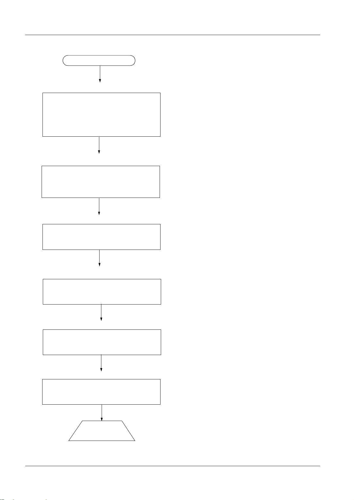
Start of maintenance
Chapter 1 General remarks
- Safety information
- Documents required
- Tools, meters and appliances
- Important notes
- Abbreviations
Chapter 2 Check of the image reader
- Half year
- One year
- Two years
- Three years
Chapter 3 Check of the acquisition workstation
- Hardware maintenance
Chapter 4 Software maintenance
- Check message files
- Backup of syngor configuration settings
Chapter 5 Check of the image quality
- Check the image quality
Chapter 6 Final work steps
- Safety check
- Protective ground/ earth measurement
End of maintenance
DIGISCAN M Register 8 SPB7-420.831.01 Page 4 of 6 Siemens-Elema AB
System Manual Rev. 02 12.02 SPS-UD Solna, Sweden
Page 9
General remarks 1 - 5
1.5 Explanation of maintenance relevant abbreviations
Abbrev. Explanation
SI Safety Inspection
SIE Electrical Safety In s p e ct io n
SIM Mechanical Safety Inspection
PM Preventiv e Maintenance
PMP Preventive Maintenance Preventive Parts Replacement, External Inspection,
etc.
PMA Preventive Maintenance Adjust ments
PMF Preventive Maintenan ce, Function Check, Operating Value Check
Q Quality Check
QIQ Image Quality Check
QSQ System Quality Check
SW Software Maintenance
The items identified by these abbreviations are contained in the maintenance certificate
and should be checked off upon completion.
1.6 Abbreviations
AWS = Acquisition Workstation
CSE = C
IP = I
MOD = M
ustomer Support Engineer
maging Plate
agneto Optical Disc
Siemens-Elema AB Register 8 SPB7-420.831.01 Page 5 of 6 DIGISCAN M
Solna, Sweden Rev. 02 12.02 SPS-UD System Manual
Page 10

1 - 6 General remarks
This page intentionally left blank.
DIGISCAN M Register 8 SPB7-420.831.01 Page 6 of 6 Siemens-Elema AB
System Manual Rev. 02 12.02 SPS-UD Solna, Sweden
Page 11

Check of the image reader 2 - 1 2 Check of the image reader
2.1 General remarks
The sequence of maintenance work steps can be found in the Fuji Service Manual FCR
5000MA plus.
The semi annual check should also be carried out during annual and biannual maintenance.
The same applies for the annual and biannual checks.
NOTE
2.1.1 Half year
PM Checking the error log
➪ Fuji checkpoint 2.1
PM Cleaning FD drive
➪ Fuji checkpoint 3.3
PM Deleting the error log
➪ Fuji checkpoint 13.
QIQ Checking the image
➪ Fuji checkpoint 14.
The safety information from Chapter 1 must be observed!
Siemens-Elema AB Register 8 SPB7-420.831.01 Page 1 of 6 DIGISCAN M
Solna, Sweden Rev. 02 12.02 SPS-UD System Manual
Page 12

2 - 2 Check of the image reader
2.1.2 One year
NOTE
Also carry out half year maintenance!
PM Removing the covers
➪ Fuji checkpoint 4.
PM Turning OFF the high-voltage switch
➪ Fuji checkpoint 5.
PM Cleaning the air filters
➪ Fuji checkpoint 6.
PM Removing cassette set unit
➪ Fuji checkpoint 7.1
PM IP removal unit
Cleaning the suction cups.
➪ Fuji checkpoint 7.2
PM IP removal unit
Cleaning the rubber rollers located under the IP removal arm and shock absorberattached guide plates.
➪ Fuji checkpoint 7.3
PM IP removal unit
Cleaning the shock absorber-attac hed guide plates located under the IP removal unit.
➪ Fuji checkpoint 7.4
PM IP removal unit
Cleaning the shock absorber-attac hed guide plates in the conv eyance path of the IP
removal uni t.
➪ Fuji checkpoint 7.5
PM IP removal unit
Cleaning the rubber rollers.
➪ Fuji checkpoint 7.6
PM Cassette set unit
Cleaning the rubber rollers.
➪ Fuji checkpoint 7.7
DIGISCAN M Register 8 SPB7-420.831.01 Page 2 of 6 Siemens-Elema AB
System Manual Rev. 02 12.02 SPS-UD Solna, Sweden
Page 13

Check of the image reader 2 - 3
PM Installing the cassette set unit
➪ Fuji checkpoint 7.8
PM Remove the erasure conveyor
➪ Fuji checkpoint 8.1
PM Erasure conveyor
Cleaning the erasure lamps.
➪ Fuji checkpoint 8.2
PM Erasure conveyor
Cleaning the cleaning rollers.
➪ Fuji checkpoint 8.3
PM Erasure conveyor
Cleaning the shock absorber-attac hed reflection plate.
➪ Fuji checkpoint 8.4
PM Erasure conveyor
Cleaning shock absorber-attached filter.
➪ Fuji checkpoint 8.5
PM Erasure conveyor
Cleaning shock absorber-attached guide plates.
➪ Fuji checkpoint 8.6
PM Erasure conveyor
Cleaning the rubber rollers.
➪ Fuji checkpoint 8.7
PM Erasure conveyor
Installing the lamp house assembl y / shock absorber-attached reflec tion plate.
➪ Fuji checkpoint 8.8
PM Erasure conveyor
Installing the cleaning rollers.
➪ Fuji checkpoint 8.9
PM Installing th e erasure conveyor
➪ Fuji checkpoint 8.10
PM Pulling out the scanner unit
➪ Fuji checkpoint 9.2
PM Removing the side-positioning conveyor
➪ Fuji checkpoint 9.3
PM Side-positioning conveyor
Siemens-Elema AB Register 8 SPB7-420.831.01 Page 3 of 6 DIGISCAN M
Solna, Sweden Rev. 02 12.02 SPS-UD System Manual
Page 14

2 - 4 Check of the image reader
Cleaning the shock absorber-attac hed guide plates.
➪ Fuji checkpoint 9.4
PM Side-positioning conveyor
Cleaning the rubber rollers.
➪ Fuji checkpoint 9.5
PM Subscanning unit
Removing the light-collecting gui de assemblies.
➪ Fuji checkpoint 9.6
PM Subscanning unit
Cleaning the light-collecting guide assemblies.
➪ Fuji checkpoint 9.7
PM Subscanning unit
Removing the scanning optics unit.
➪ Fuji checkpoint 9.8
PM Subscanning unit
Cleaning the light-collecting mirror.
➪ Fuji checkpoint 9.9
PM Subscanning unit
Cleaning the rubber rollers.
➪ Fuji checkpoint 9.10
PM Subscanning unit
Cleaning the shock abs orber-attached c enter guide plate / shoc k absorber -attached guid e
plate.
➪ Fuji checkpoint 9.11
PM Subscanning unit
Cleaning the glass guide.
➪ Fuji checkpoint 9.12
PM Subcleaning unit
Installing the scanning optics unit.
➪ Fuji checkpoint 9.14
PM Subscanning unit
Installing the light-collecting guide assemblies.
➪ Fuji checkpoint 9.15
PM Installing the side-positioning conveyor
➪ Fuji checkpoint 9.16
DIGISCAN M Register 8 SPB7-420.831.01 Page 4 of 6 Siemens-Elema AB
System Manual Rev. 02 12.02 SPS-UD Solna, Sweden
Page 15

Check of the image reader 2 - 5
PM Pushing in the scanner unit
➪ Fuji checkpoint 9.17
PM Turning on the high-voltage switch
➪ Fuji checkpoint 10.
PM Installing and cleaning the covers
➪ Fuji checkpoint 11.
PM Checking the date and time
➪ Fuji checkpoint 12.
2.1.3 Two years
NOTE
Also carry out half year and one year maintenance!
PMP Replacing the air filters
➪ Fuji checkpoint 6.
PMP Erasure conveyor
Replacing the erasure lamps.
➪ Fuji checkpoint 8.2
PMP Erasure conveyor
Replacing the cleaning rollers.
➪ Fuji checkpoint 8.3
PM Subscanning unit
Cleaning the SUS belt / rubber belt / kapton belt.
➪ Fuji checkpoint 9.1
Siemens-Elema AB Register 8 SPB7-420.831.01 Page 5 of 6 DIGISCAN M
Solna, Sweden Rev. 02 12.02 SPS-UD System Manual
Page 16

2 - 6 Check of the image reader
2.1.4 Three years
NOTE
Also carry out half, one and two year maintenance!
PMP IP removal unit
Replacing the rubber rollers located under the IP removal arm and shock absorberattached guide plates.
➪ Fuji checkpoint 7.3
PMP IP removal unit
Replacing the shock absorber-attached guide plates located under the IP removal unit.
➪ Fuji checkpoint 7.4
PMP IP removal unit
Replacing the shock absorber-attached guide plates in the conveyance path of the IP
removal uni t.
➪ Fuji checkpoint 7.5
PMP Erasure conveyor
Replacing the shock absorber-attached reflection plate .
➪ Fuji checkpoint 8.4
PMP Erasure conveyor
Replacing shock absorber-attached filter.
➪ Fuji checkpoint 8.5
PMP Erasure conveyor
Replacing shock absorber-attached guide plates.
➪ Fuji checkpoint 8.6
PMP Side-positioning conveyor
Replacing the shock absorber-attached guide plates.
➪ Fuji checkpoint 9.4
PMP Subscanning unit
Replacing the shock absorber-attached center guide plate / shock absorber-attached
guide plate.
➪ Fuji checkpoint 9.13
DIGISCAN M Register 8 SPB7-420.831.01 Page 6 of 6 Siemens-Elema AB
System Manual Rev. 02 12.02 SPS-UD Solna, Sweden
Page 17

Check of the acquisition workstation 3 - 1 3 Check of the acquisition workstation
3.1 Hardware maintenance
3.1.1 Computer
PM Secure mechanical adjustment
• Ensure that all devices are securely placed on the desktop.
PM Fans - check proper operation and direction of the airflow
• Check proper operation and correct direction of the airflo w.
PM Fans - cleaning
• Clean all fans of dust.
PM Check internal cables and plugs
• Check that all cables are properly connected to the devices.
PM Cleaning
• Use a brush and vacuum cleaner to clean the computer cabinet of dust.
NOTE
3.1.2 Cables
PM Check if cables are squeezed or broken
• Check that the cables are neither squeezed nor broken; if they are they must be
replaced.
PM Check all external cable connections
• Check that all cables are properly connected.
PM Safe cable lay
• Check that all cables are placed in a way that no one will trip over t hem.
3.1.3 Keyboard and mouse
PM Keyboard - cleaning
• Use household pads to clean the keyboard of dust and residue.
• Be careful that no liquid gets inside the keyboard.
PM Mouse - operational Check
Be sure to follow the ESD guidelines.
• Check that the mouse is operational. Open the mouse and clean the rolls inside th e
housing.
PM Mouse - cleaning
• Clean the mouse and replace the mouse pad if necessary.
Siemens-Elema AB Register 8 SPB7-420.831.01 Page 1 of 2 DIGISCAN M
Solna, Sweden Rev. 02 12.02 SPS-UD System Manual
Page 18

3 - 2 Check of the acquisition workstation
3.1.4 Monitor
PM Cleaning
• Use household pads to clean the dust from the screen and housing of every monit or.
3.1.5 Barcode scanner
PM Checking the barcode scanner
• Call up Start > Programs > Accessories > WordPad.
• Read the projection view barcodes.
DIGISCAN M Register 8 SPB7-420.831.01 Page 2 of 2 Siemens-Elema AB
System Manual Rev. 02 12.02 SPS-UD Solna, Sweden
Page 19

Software maintenance 4 - 1 4 Software maintenance
4.1 Acquisition workstation software update
SW Installation of recommended acquisition workstation software updates
• Optional updates should only be installed on systems where a specific problem persists
and where a software update would solve the pro blem.
• A list of solved problems can be found in the corresponding UI (Update Instruct ion),
which is released with the software update.
4.2 Checks on syngo level
4.2.1 Check “messages” files
SW Check “messages” files for error messages
• Log in as “meduser”.
• Select Options > Service > Local Servi ce in the window menu header.
• Enter the service key (14 character in 1st mask and 6 character in 2nd mask).
• Confirm with OK.
Siemens-Elema AB Register 8 SPB7-420.831.01 Page 1 of 4 DIGISCAN M
Solna, Sweden Rev. 02 12.02 SPS-UD System Manual
Page 20

4 - 2 Software maintenance
The Service Home menu appears.
• Select Event Log in header.
DIGISCAN M Register 8 SPB7-420.831.01 Page 2 of 4 Siemens-Elema AB
System Manual Rev. 02 12.02 SPS-UD Solna, Sweden
Page 21

Software maintenance 4 - 3
• Select the appropriate eventlog file here.
• Select the period of time under consideration in Time Range.
• Evaluate the corresponding error messages for conspicuous features.
• Close the window by clicking in the upper right corner.
4.3 Backup of syngo configuration data
SW Backup of configuration data
• For details, please refer to DIGISCAN M Software acquisition workstation, SPB7-
420.816.01... .
• Store the data on a floppy disk.
Siemens-Elema AB Register 8 SPB7-420.831.01 Page 3 of 4 DIGISCAN M
Solna, Sweden Rev. 02 12.02 SPS-UD System Manual
Page 22

4 - 4 Software maintenance
This page intentionally left blank.
DIGISCAN M Register 8 SPB7-420.831.01 Page 4 of 4 Siemens-Elema AB
System Manual Rev. 02 12.02 SPS-UD Solna, Sweden
Page 23

Check of the image quality 5 - 1 5 Check of the image quality
QIQ Phantom image quality
• Perform the test according to DIGISCAN M Quality Control Manual, SPB7-420.210.01...
QIQ Display and print conformity
• Perform the test according to DIGISCAN M Quality Control Manual, SPB7-420.210.01...
QIQ Homogeneity
• Perform the test according to DIGISCAN M Quality Control Manual, SPB7-420.210.01...
Siemens-Elema AB Register 8 SPB7-420.831.01 Page 1 of 2 DIGISCAN M
Solna, Sweden Rev. 02 12.02 SPS-UD System Manual
Page 24

5 - 2 Check of the image quality
This page intentionally left blank.
DIGISCAN M Register 8 SPB7-420.831.01 Page 2 of 2 Siemens-Elema AB
System Manual Rev. 02 12.02 SPS-UD Solna, Sweden
Page 25

Final work steps 6 - 1 6 Final work steps
PM Checking the cover panels
• Install all cover panels or check them for secure seating.
PM Touch up paint scratches / chips
SI Protective ground / earth measurement
Components which can be detached from the mains cable i.e. acquisition workstation,
SIMOMED monitor (option) and MOD drive (option).
• Using the protective ground wire tester, measure the resistanc e between the protective
ground terminal of the equipment and all metall ic parts of the equipment (including LCD
monitor for acquisition works tation) which the patient / operator may come in cont act
with. The protective ground resistance must not exceed 0.1 Ω (observe local
regulations).
• Measure the resistance between the ground connections of the mains cable ends. The
protective ground resistance must not ex ceed 0.1 Ω (observe local regulati ons).
SI Protective ground / earth measurement
Components which can not be detached from the mains cable i.e. image reader.
• Using the protective ground wire tester, measure the resistanc e between the ground
connection of the mains cable end and all metalli c parts of the equipment which the
patient / operator may come in contact with . The protective ground resistance must n ot
exceed 0.2 Ω (observe local regulations) .
Siemens-Elema AB Register 8 SPB7-420.831.01 Page 1 of 2 DIGISCAN M
Solna, Sweden Rev. 02 12.02 SPS-UD System Manual
Page 26

6 - 2 Final work steps
This page intentionally left blank.
DIGISCAN M Register 8 SPB7-420.831.01 Page 2 of 2 Siemens-Elema AB
System Manual Rev. 02 12.02 SPS-UD Solna, Sweden
Page 27

Changes to previous version 7 - 1 7 Changes to previous version
Page Chapter Change
4-1
4-1
4-1
Check “messages” files for
error mes sa g e s
Check “messages” files for
error mes sa g e s
Check “messages” files for
error mes sa g e s
Second step is rewritten.
Picture replaced in second step.
Picture replaced in fourth step.
Siemens-Elema AB Register 8 SPB7-420.831.01 Page 1 of 2 DIGISCAN M
Solna, Sweden Rev. 02 12.02 SPS-UD System Manual
Page 28

7 - 2 Changes to previous version
This page intentionally left blank.
DIGISCAN M Register 8 SPB7-420.831.01 Page 2 of 2 Siemens-Elema AB
System Manual Rev. 02 12.02 SPS-UD Solna, Sweden
 Loading...