

Page 1

DIGISCAN M
System Manual
Wiring Diagrams
including Function De scrip ti o n
SP
© Siemens AG 2002
The reproduction, transmission or
use of this document or its contents
is not permitted without express
written authority. Offenders will be
liable for damages. All rights,
including rights created by patent
grant or registration of a utility
model _or_ design,_are_ reserved.
Register 6 English
Print No.: SPB7-420.844.01.02.02 Doc . Gen. Date: 11.02
Replaces: SPB7-420.844.01.01.02 66 31 167
Page 2

0 - 2 Revision
Chapter Page Revision
All All 02
Document revision level
The document corresponds to the version/revision level effective at the time of system delivery. Revisions to hardcopy documentation are not automatically distributed.
Please contact your local Siemens office to order current revision levels.
Disclaimer
The installation and service of equipment described herein is to be performed by qualified personnel
who are employed by Siemens or one of its affiliates or who are otherwise authorized by Siemens or
one of its affiliates to provide such services.
Assemblers and other persons who are not employed by or otherwise directly affiliated with or authorized by Siemens or one of its affiliates are directed to contact one of the local offices of Siemens or
one of its affiliates before attempti ng installation or service procedures.
DIGISCAN M Register 6 SPB7-420.844.01 Page 2 of 4 Siemens-Elema AB
System Manual Rev. 02 11.02 SPS-UD Solna, Sweden
Page 3

Contents 0 - 3
Page
1 _______System overview_______________________________________________1 - 1
General . . . . . . . . . . . . . . . . . . . . . . . . . . . . . . . . . . . . . . . . . 1 - 1
Documents required. . . . . . . . . . . . . . . . . . . . . . . . . . . . . . . . . . .1 - 1
DIGISCAN M (standard system) . . . . . . . . . . . . . . . . . . . . . . . . . . . .1 - 1
Additional parts to the DIGISCAN M system . . . . . . . . . . . . . . . . . . . . 1 - 2
Abbreviations . . . . . . . . . . . . . . . . . . . . . . . . . . . . . . . . . . . . . . 1 - 2
2 _______Diagrams _____________________________________________________2 - 1
Cable connections. . . . . . . . . . . . . . . . . . . . . . . . . . . . . . . . . . . . 2 - 1
Block diagram . . . . . . . . . . . . . . . . . . . . . . . . . . . . . . . . . . . . . . 2 - 2
3 _______Connectors____________________________________________________3 - 1
Acquisition works tation connectors . . . . . . . . . . . . . . . . . . . . . . . . . . . 3 - 1
4 _______Function description____________________________________________4 - 1
5 _______List of components _____________________________________________5 - 1
Cables . . . . . . . . . . . . . . . . . . . . . . . . . . . . . . . . . . . . . . . . . .5 - 1
Fuses . . . . . . . . . . . . . . . . . . . . . . . . . . . . . . . . . . . . . . . . . . 5 - 2
6 _______Changes to previous version_____________________________________6 - 1
Siemens-Elema AB Register 6 SPB7-420.844.01 Page 3 of 4 DIGISCAN M
Solna, Sweden Rev. 02 11.02 SPS-UD System Manual
Page 4

0 - 4 Contents
This page intentionally left blank.
DIGISCAN M Register 6 SPB7-420.844.01 Page 4 of 4 Siemens-Elema AB
System Manual Rev. 02 11.02 SPS-UD Solna, Sweden
Page 5
System overview 1
5.2 GB
General 1
This document shows the main functions of the DIGISCAN M system and the electrical
connections between the parts. For detailed information about electrical components
within the parts and options, see product-accompanying documentation.
Documents required 1
• MAMMOMAT 3000 Nova Wiring Diagrams
• Product-accompanying documentation
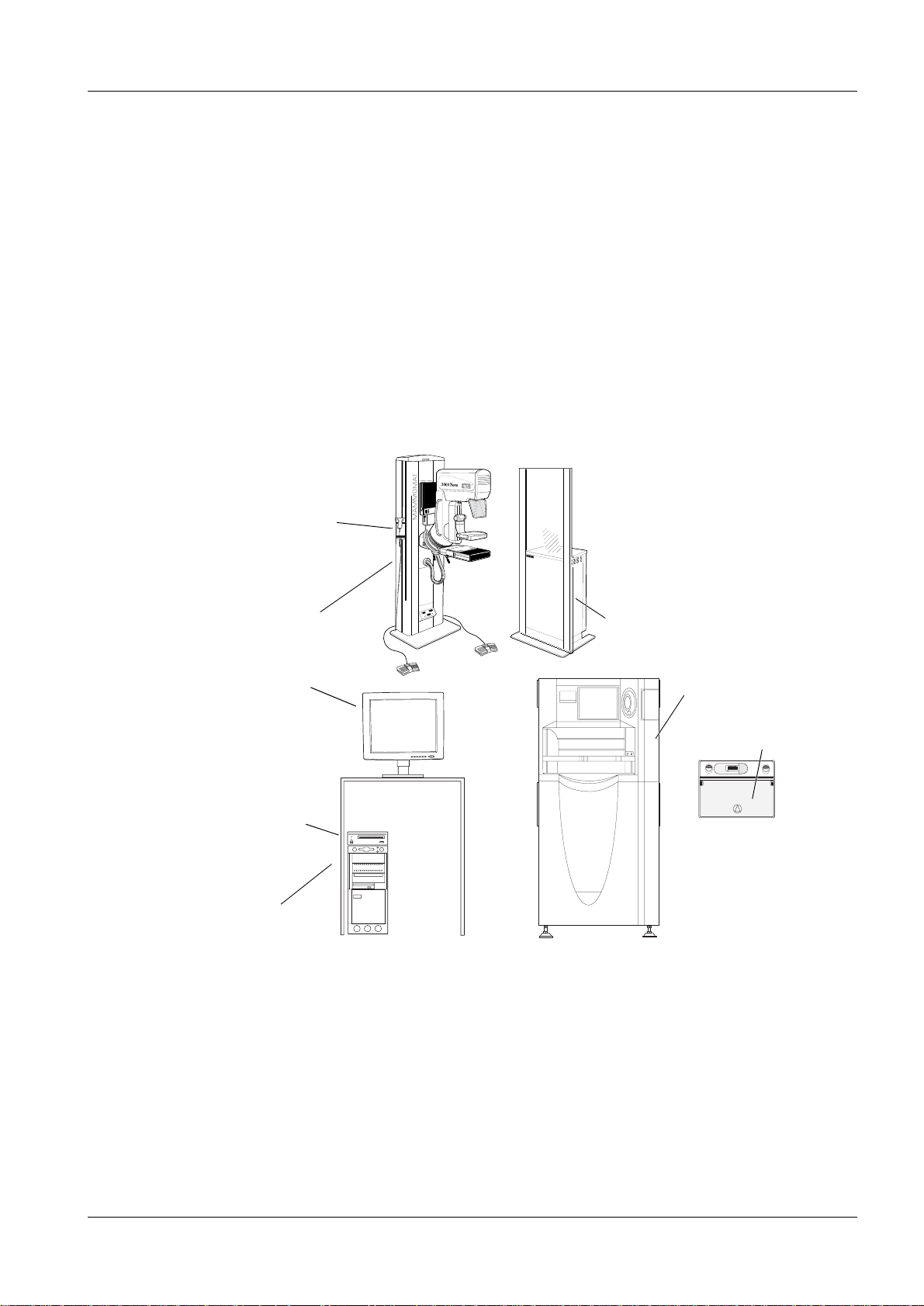
DIGISCAN M (standard system) 1
An overview of the DIGISCAN M system is provided below. The options of the standard
system are appropriately identified.
Barcode scanner
1 - 1
Stand
with X-ray unit
LCD monitor
SIMOMED
monitor (option)
MOD drive (option)
Acquisition workstation
Fig. 1
SONY
BUSY
POWER
5.2 GB
CELSIUS
Generator
Image reader
IP cassette
A30008711C HR-BD
MO
DISK
UNIT
RMO-S551
EJECT
400
FFDM00002
Siemens-Elema AB Register 6 SPB7-420.844.01 Page 1 of 2 DIGISCAN M
Solna, Sweden Rev. 02 11.02 SPS-UD System Manual
Page 6

1 - 2 System overview
Additional parts to the DIGISCAN M system 1
NOTE
For actual system options, see price book.
• Viewing station
• Archive system
• Hardcopy camera
NOTE
Use only released hardcopy cameras or a hardcopy camera that
can receive DICOM print, has a resolution of 50x50 µm,
density W 3.5 and can print 18x24 and 24x30 film format.
• HIS/RIS
• Communication switch
Abbreviations 1
CPU = C
DICOM = D
EDR = E
HDD = H
HIS = H
IP = I
LCD = L
MOD = M
RAM = R
RIS = R
SCSI = S
entral Processing Unit
igital Imaging and Communication in Medicine
xposure Data Recognizer
ard Disk Drive
ospital Information System
maging Plate
iquid Crystal Display
agneto Optical Disc
andom Access Memory
adiology Information System
mall Computer System Interface
DIGISCAN M Register 6 SPB7-420.844.01 Page 2 of 2 Siemens-Elema AB
System Manual Rev. 02 11.02 SPS-UD Solna, Sweden
Page 7

Diagrams 2
s
Cable connections 2
2 - 1
Incoming mains
MOD drive
MAMMOMAT
3000 Nova
Mouse
Biopsy controller
Communication
switch
SIMOMED monitor
Acquisition workstation
LCD monitor
Barcode scanner
Keyboard
Incoming main
Image reader
CPU90F-LAN
Incoming mains
Fig. 1 Cable connections
Viewing station
Hardcopy camera
Network
HIS/RIS
Archive system
= Option
= If no biopsy controller
Incoming mains
FFDM00581
Siemens-Elema AB Register 6 SPB7-420.844.01 Page 1 of 2 DIGISCAN M
Solna, Sweden Rev. 02 11.02 SPS-UD System Manual
Page 8

2 - 2 Diagrams
Block diagr am 2
NOTE
The acquisition workstat io n and the ima ge reader can handl e 100240 V.
For instructions how to connect MAMMOMAT 3000 Nova to the
mains, see MAMMOMAT 3000 Nova Wiring Diagrams.
Incoming mains
100-125 / 200-240 V, 3.3 / 1.5 A
Mains filter
Mains switch
Power supply
CD drive
Floppy
HDD
x3
Acquisition workstation
Monitor
Graphics acc.
CPU
RAM
Network
MOD drive
Network
Incoming mains
Single phase
100-240 V +10%, 8.0 / 3.3 A
Mains switch
Power supply
CPU90F
CPU90E
Image reader
JPS-6
IMG07B
EDR
HDD
Biopsy
controller
Communication
switch
Incoming mains
Fig. 2 Block diagram
D707
D702
Network
M3000 Nova
generator
Barcode
scanner
Keyboard
= Galvanic separation
= Option
= If no biopsy controller
FFDM00582
DIGISCAN M Register 6 SPB7-420.844.01 Page 2 of 2 Siemens-Elema AB
System Manual Rev. 02 11.02 SPS-UD Solna, Sweden
Page 9

Connectors 3
F
Acquisition workstation connectors 3
1
2
3
4
6
5
3 - 1
10
7
8
9
Fig. 1 Acquisition workstation connections
1 Mains power supply
2 Mains supply for LCD monitor
3 Keyboard interface (also power supply for barcode scanner)
4 Mouse interfa c e
5
MAMMOMAT interface
6
Dongle interface
7 Monitor inter fa ce
8 Image reader connector
9 Network connector
10 Barcode scanner interface
FDM00544
NOTE
For information how to connect the options, see product-accompanying documentation.
Siemens-Elema AB Register 6 SPB7-420.844.01 Page 1 of 2 DIGISCAN M
Solna, Sweden Rev. 02 11.02 SPS-UD System Manual
Page 10

3 - 2 Connectors
This page intentionally left blank.
DIGISCAN M Register 6 SPB7-420.844.01 Page 2 of 2 Siemens-Elema AB
System Manual Rev. 02 11.02 SPS-UD Solna, Sweden
Page 11

Function description 4
For name of system components see Fig. 2, Page 2 - 2 “Block diagram”.
Cassette including a high resolution Computed Radiography (CR) imaging plate is
exposed in the MAMMOMAT 3000 Nova. (IP cassette)
After exposure, the identification barcode of the used IP cassette is read by means of a
barcode scanner and with the same device, a barcode is read representing the object
view used at the e xposure. These data are fed to the acquisition workstation and associ-
ated to the patient under examination.
The cassette is enter ed i nto t he image r eader where the cassett e iden tifi cati on ba rcode i s
read. The image reader ask the acquisition workstati on, via network connection between
acquisition workstation and image reader, which patient data is associated with the cas-
sette.
When patient data is estab l ish ed in t he image r eader, the read out process of the imaging
plate starts and the digital image and patient data are stored in a file on the reader HDD.
The gray scale depth of this image is 11bit/pixel.
The image data is transformed in a computing process called EDR to a image with gray
scale depth of 10 bit/pixel and transferred to the acquisition workstation together with the
patient data.
4 - 1
In the acquisition w orkstation, data fr om connected unit s are collect ed and co-ordina ted to
control current study and display results from current study as well as store the study and
its images.
Via a network or local recourses , images or studie s can be sav ed, tr ansferred, re triev ed or
output to hardcopy camera.
Images are stored or output in DICOM-format.
Siemens-Elema AB Register 6 SPB7-420.844.01 Page 1 of 2 DIGISCAN M
Solna, Sweden Rev. 02 11.02 SPS-UD System Manual
Page 12

4 - 2 Function description
This page intentionally left blank.
DIGISCAN M Register 6 SPB7-420.844.01 Page 2 of 2 Siemens-Elema AB
System Manual Rev. 02 11.02 SPS-UD Solna, Sweden
Page 13

List of components 5
Cables 5
Cable between Connector type Length Transmitted data Comments
5 - 1
Acquisition
workstation
Acquisition
workstation
Acquisition
workstation
Acquisition
workstation
Barcode
scanner cable
Acquisition
workstation
Acquisition
workstation
LCD monitor DVI-D DVI-D 1 m Monitor image
SIMOMED
monitor
Keyboard PS/2 PS/2 1.5 m Keyboard
Barcode
scanner cable
Barcode
scanner
Image reader
Hardcopy
camera if no
network
M3000 Nova
stand or
communication switch
HDDB15M
Acquisition workstation
DB9F Datalogic
RJ45
Red
PC X205 15 m RS232
HD-DB15M 1 m Monitor image
Scanner 15 m RS232
Barcode data
1.5 m Barcode data
scanner
connector
RJ45
Red
20 m Ethernet, cat. 5 cable
(crossed-over)
FINP/ OEM
Patient and barcode
data
Exposure parameters
Siemens
material No.
66 09 569
Siemens
material No.
66 01 616
Siemens
material No.
66 09 551
M3000 Nova
generator
M3000 Nova Mains See MAMMOMAT 3000 Nova
Acquisition
workstation
Acquisition
workstation
Network Archive
Network HIS/RIS RJ45 RJ45 * Ethernet, cat. 5 cable
Network Viewing
M3000 Nova
stand
MOD drive Centronics
Network RJ45 RJ45 25 m Ethernet, cat. 5 cable
system
station
X2 X205 6 m RS232
Exposure parameters
Incoming mains
Wiring Diagrams
HPDB 50 2 m SCSI 2
C50
RJ45 RJ45 * Ethernet, cat. 5 cable
RJ45 RJ45 * Ethernet, cat. 5 cable
Patient and ima ge data,
DICOM
Patient and ima ge data,
DICOM
Image data, DICOM
Patient data, DICOM
Image data, DICOM
Siemens
material No.
66 09 593
Siemens
material No.
66 01 582
Siemens-Elema AB Register 6 SPB7-420.844.01 Page 1 of 2 DIGISCAN M
Solna, Sweden Rev. 02 11.02 SPS-UD System Manual
Page 14

5 - 2 List of components
Network Hardcopy
camera
* see product-accompanying documentation.
Fuses 5
See product-accompanying documentation.
RJ45 RJ45 * Ethernet, cat. 5 cable
DICOM print
DIGISCAN M Register 6 SPB7-420.844.01 Page 2 of 2 Siemens-Elema AB
System Manual Rev. 02 11.02 SPS-UD Solna, Sweden
Page 15

Changes to previous version 6
Page Chapter Change
6 - 1
1-2 Additional parts to the
DIGISCAN M system
1-2 Abbreviations Corrected explanation of the abbreviation
2-1 Cable connections Communication switch (option) is added to
2-2 Block diagram Communication switch (option) is added to
3-1 Acquisition workstation connec-
tors
5-1 Cables Datatype for cab le between acquisition work-
Text changes.
RAM.
the figure.
New connections for barcode scanner and
keyboard is added to the figure.
the figure.
New connections for barcode scanner and
keyboard is added to the figure.
Number 3 is keyboard interface and power
supply for the barcode scanner.
Number 6 is dongle interface.
Number 10 is barcode scanner interface.
station and keyboard has changed to only
keyboard.
Cable between Acquisiti on workstation and
barcode decoder remov ed.
Cable between Acquisition workstation Barcode scanner cable is added
Cable between acquisition workstation and
image reader (or hardcopy camer a if no network) changed to 20 m.
Cable between acquisition workstation and
M3000 Nova stand or communication switch
changed to 15 m.
“*” are new.
5-2 Cables Lenght of cable between net work an d view-
ing station is approximately 25 m.
Siemens-Elema AB Register 6 SPB7-420.844.01 Page 1 of 2 DIGISCAN M
Solna, Sweden Rev. 02 11.02 SPS-UD System Manual
Page 16

6 - 2 Changes to previous version
This page intentionally left blank.
DIGISCAN M Register 6 SPB7-420.844.01 Page 2 of 2 Siemens-Elema AB
System Manual Rev. 02 11.02 SPS-UD Solna, Sweden
 Loading...