

Page 1

DIGISCAN M
System Manual
Installation Instructions
System unpacking, installation and cabling
SP
© Siemens AG 2002
The reproduction, transmission or
use of this document or its contents
is not permitted without express
written authority. Offenders will be
liable for damages. All rights,
including rights created by patent
grant or registration of a utility
model _or_ design,_are_ reserved.
Register 3 English
Print No.: SPB7-420.812.01.03.02 Doc . Gen. Date: 11.02
Replaces: SPB7-420.201.812.01.02.02 66 31 142
Page 2

0 - 2 Revision
Chapter Page Revision
All All 03
Document revision level
The document corresponds to the version/revision level effective at the time of system delivery. Revisions to hardcopy documentation are not automatically distributed.
Please contact your local Siemens office to order current revision levels.
Disclaimer
The installation and service of equipment described herein is to be performed by qualified personnel
who are employed by Siemens or one of its affiliates or who are otherwise authorized by Siemens or
one of its affiliates to provide such services.
Assemblers and other persons who are not employed by or otherwise directly affiliated with or authorized by Siemens or one of its affiliates are directed to contact one of the local offices of Siemens or
one of its affiliates before attempti ng installation or service procedures.
DIGISCAN M Register 3 SPB7-420.812.01 Page 2 of 4 Siemens-Elema AB
System Manual Rev. 03 11.02 SPS-UD Solna, Sweden
Page 3

Contents 0 - 3
Page
1 _______Introduction ___________________________________________________1 - 1
Safety information . . . . . . . . . . . . . . . . . . . . . . . . . . . . . . . . . . . . 1 - 1
Documents required. . . . . . . . . . . . . . . . . . . . . . . . . . . . . . . . . . .1 - 1
Prerequisites . . . . . . . . . . . . . . . . . . . . . . . . . . . . . . . . . . . . . . 1 - 1
Important notes on installation . . . . . . . . . . . . . . . . . . . . . . . . . . . . . 1 - 1
Basic information . . . . . . . . . . . . . . . . . . . . . . . . . . . . . . . . . . 1 - 1
Unpacking, transport and installation . . . . . . . . . . . . . . . . . . . . . . . . 1 - 1
Unpacking . . . . . . . . . . . . . . . . . . . . . . . . . . . . . . . . . . . . . . 1 - 2
Transport routes . . . . . . . . . . . . . . . . . . . . . . . . . . . . . . . . . . . 1 - 2
Cleaning . . . . . . . . . . . . . . . . . . . . . . . . . . . . . . . . . . . . . . . 1 - 2
Overview of DIGISCAN M (standard system). . . . . . . . . . . . . . . . . . . . . . 1 - 3
Additional parts to the DIGISCAN M system . . . . . . . . . . . . . . . . . . . . 1 - 3
Installation sequence . . . . . . . . . . . . . . . . . . . . . . . . . . . . . . . . . . 1 - 4
Abbreviations . . . . . . . . . . . . . . . . . . . . . . . . . . . . . . . . . . . . . . 1 - 6
2 _______Unpacking and setup ___________________________________________2 - 1
Important information for the Siemens employee . . . . . . . . . . . . . . . . . . . . 2 - 1
Checking for completeness . . . . . . . . . . . . . . . . . . . . . . . . . . . . . . . 2 - 1
Unpacking and setup of the acq uisition workstation . . . . . . . . . . . . . . . . . . 2 - 2
Unpacking . . . . . . . . . . . . . . . . . . . . . . . . . . . . . . . . . . . . . . 2 - 2
Transport . . . . . . . . . . . . . . . . . . . . . . . . . . . . . . . . . . . . . . 2 - 2
Setup . . . . . . . . . . . . . . . . . . . . . . . . . . . . . . . . . . . . . . . . 2 - 2
Unpacking and setup of the image reader . . . . . . . . . . . . . . . . . . . . . . .2 - 3
General remarks. . . . . . . . . . . . . . . . . . . . . . . . . . . . . . . . . . . 2 - 3
Preparation . . . . . . . . . . . . . . . . . . . . . . . . . . . . . . . . . . . . . 2 - 3
Transporting the parts to the installation site . . . . . . . . . . . . . . . . . . . . 2 - 4
Unpacking and setup of the viewing station (option) . . . . . . . . . . . . . . . . . .2 - 6
Unpacking / Transport . . . . . . . . . . . . . . . . . . . . . . . . . . . . . . . . 2 - 6
Unpacking and setup of the options. . . . . . . . . . . . . . . . . . . . . . . . . . . 2 - 7
MOD drive (option to acquisition workstation) . . . . . . . . . . . . . . . . . . . .2 - 7
Communication switch (option) . . . . . . . . . . . . . . . . . . . . . . . . . . . 2 - 7
3 _______System cabling ________________________________________________3 - 1
Laying and connecting the cables. . . . . . . . . . . . . . . . . . . . . . . . . . . . 3 - 1
Cable duct . . . . . . . . . . . . . . . . . . . . . . . . . . . . . . . . . . . . . . . .3 - 1
Cable connections. . . . . . . . . . . . . . . . . . . . . . . . . . . . . . . . . . . . 3 - 2
Ferrite cores . . . . . . . . . . . . . . . . . . . . . . . . . . . . . . . . . . . . . . .3 - 6
4 _______Final procedures _______________________________________________4 - 1
Remaining work steps. . . . . . . . . . . . . . . . . . . . . . . . . . . . . . . . . . 4 - 1
Completing the installation protocol . . . . . . . . . . . . . . . . . . . . . . . . . . . 4 - 1
5 _______Installation protocol ____________________________________________5 - 1
Siemens-Elema AB Register 3 SPB7-420.812.01 Page 3 of 4 DIGISCAN M
Solna, Sweden Rev. 03 11.02 SPS-UD System Manual
Page 4

0 - 4 Contents
6 ______ Changes to previous version _________________ __ ___ _______________6 - 1
DIGISCAN M Register 3 SPB7-420.812.01 Page 4 of 4 Siemens-Elema AB
System Manual Rev. 03 11.02 SPS-UD Solna, Sweden
Page 5

Introduction 1
Safety information 1
When carrying out the work steps and test, the product-specific safety information contained in this document, as well as the general safety information must be observed.
All texts mark ed with call attention to potential risks for health or life.
Documents required 1
• DIGISCAN M Wiring Diagrams in cluding Function Description SPB7-420.844.01...
• Product-accompanying documentation
Tools, meters and appliances required
Standard installation tool kit.
Prerequisites 1
The Installation and Start-Up of the MAMMOMAT 3000 Nova must be completed according to the appropriate SPB7-230.033... instructions.
1 - 1
Important notes on installation 1
Basic information 1
In some countries the image reader is installed, maintained and serviced by the local Fuji
organization. For further information, contact your local Siemens marketing representative.
NOTICE
Unpacking, transport and installation 1
NOTICE
CAUTION
The system responsibility is always within Siemens.
If the image reader is installed by Fuji the installation certificate
has to be filled out, see Page 5 - 1.
All components and accessories in a DIGISCAN M system, including the options, are comprised of high-quality electronic parts.
The components should be transported with extreme care using
suitable transport devices.
Risk of injury!
The picture tube in the SIMOMED monitor (option) is v acuum
parts and can implode if struck, scratched or dropped.
CAUTION
Siemens-Elema AB Register 3 SPB7-420.812.01 Page 1 of 6 DIGISCAN M
Solna, Sweden Rev. 03 11.02 SPS-UD System Manual
Risk of damage to property.
The hard disk drive of the image reader is structurally attached
under the top cover.
Do not give any shock to the top co ver of the image reader.
Page 6

1 - 2 Introduction
Unpacking 1
NOTICE
The directional markings on the crates absolutely must be observed during transport,
storage and unpacking.
Because of the risk of accidents a nd endan germent of the cont ents , use only pr oper to ols
(nail puller) when unpacking the crates.
Pull out only those nails from the crate boards that have a cardboard or metal disk under
the nail heads.
CAUTION
The person doing the unpacking ma y not mix up the contents of
the individual cartons.
The contents of the individual cartons must be brought into the
room and kept separated.
To avoid risk of injury, completely remove nails and dispose of
them properly.
Wear safety shoes!
If the crate was also secured with metal straps, take extra care
when cutting them; they can lash back unexpectedly.
In such situations, there is particular risk of accident for eyes!
Transport routes 1
The transport routes should be selected so that the image reader components are subjected to as little stress as possible caused by vibration and dust.
The route should also be selected so that a minimum door opening width of 1100 mm is
maintained.
NOTE
If the door opening is narrower than 1100 mm, the image reader
has to be unpacked outside the roo m.
Cleaning 1
The units may only be wiped down with a cloth moistened with a cleaning agent.
Sprayed water is not permitted.
For further information, see product-accompanying documentation.
DIGISCAN M Register 3 SPB7-420.812.01 Page 2 of 6 Siemens-Elema AB
System Manual Rev. 03 11.02 SPS-UD Solna, Sweden
Page 7
Introduction 1 - 3
5.2 GB
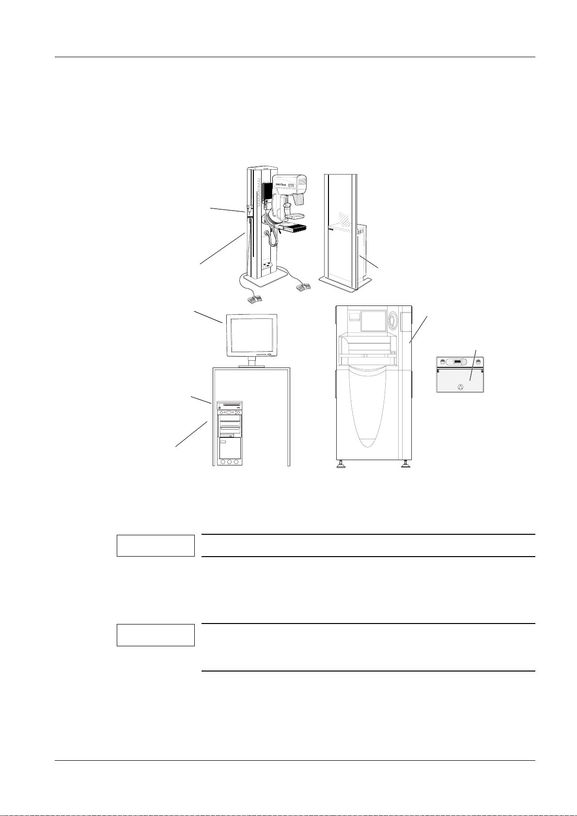
Overview of DIGISCAN M (standard system) 1
An overview of the DIGISCAN M system is provided below. The options of the standard
system are appropriately identified.
For detailed information ho w to arrange the components, see DIGISCAN M Planning
Guide, SPB7-420.891.01... and produc t-accompanying documentation.
Barcode scanner
Stand
with X-ray unit
LCD monitor
SIMOMED
Generator
Image reader
monitor (option)
IP cassette
A30008711C HR-BD
MOD drive (option)
Acquisition workstation
SONY
BUSY
POWER
5.2 GB
CELSIUS
MO
DISK
UNIT
RMO-S551
EJECT
400
FFDM00002
Fig. 1
Additional parts to the DIGISCAN M system 1
NOTE
For actual system options, see price book.
• Viewing station
• Archive system
• Hardcopy camera
NOTE
Use only released hardcopy cameras or a hardcopy camera that
can receive DICOM print, has a resolution of 50x50 µm,
density W 3.5 and can print 18x24 and 24x30 film format.
• HIS/RIS
• Communication switch
Siemens-Elema AB Register 3 SPB7-420.812.01 Page 3 of 6 DIGISCAN M
Solna, Sweden Rev. 03 11.02 SPS-UD System Manual
Page 8
1 - 4 Introduction
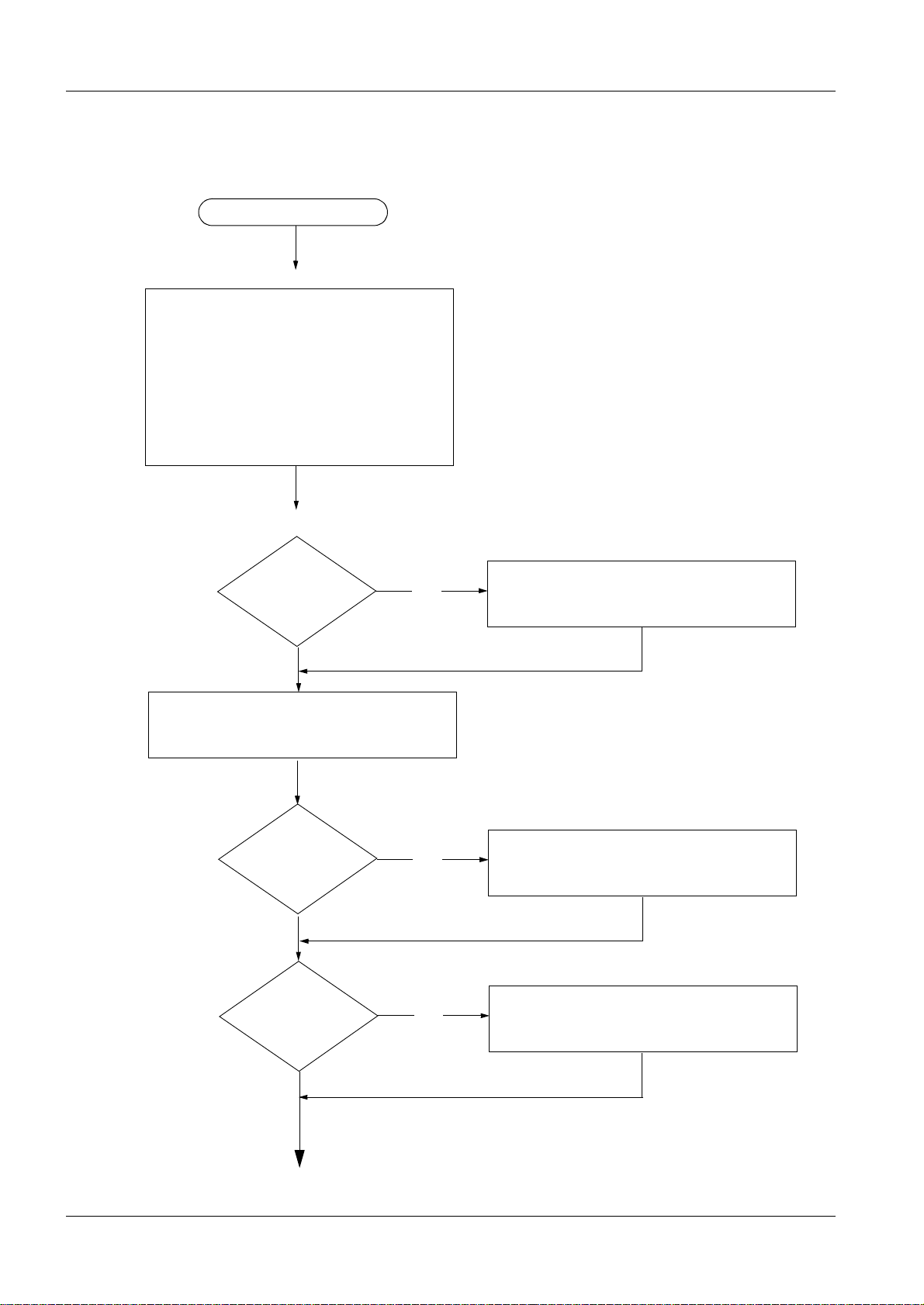
Installation sequence 1
Start of installation
Chapter 1 Introduction
- Safety information
- Documents required
- Tools, meters and appliances
- Prerequisites
- Important notes
- Overview of DIGISCAN M
- Abbreviations
Chapter 2
Unpacking and setup
Hardcopy camera
configured?
No
Check for completeness
Image reader in-
stalled by Siemens?
No
Yes
Yes
Make an appointment with the hardcopy
camera manufacturer at least 2 days prior to starting the installation
Unpack and setup the image reader
Image reader in-
stalled by Fuji?
Yes
In the installation protocol, fill out the
boxes related to the image reader and
sign it (Fuji and Siemens employee)
No
DIGISCAN M Register 3 SPB7-420.812.01 Page 4 of 6 Siemens-Elema AB
System Manual Rev. 03 11.02 SPS-UD Solna, Sweden
Page 9
Introduction 1 - 5
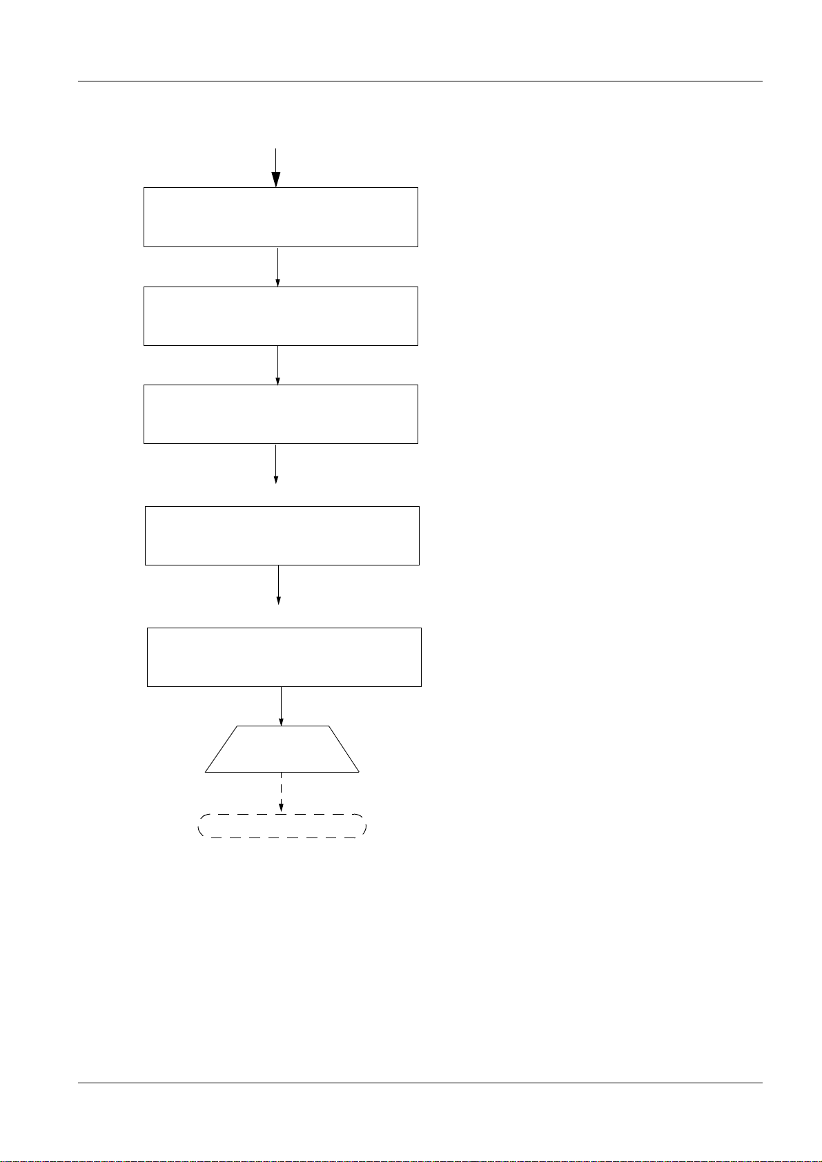
Unpack and setup the acquisition workstation
Unpack and setup the viewing station (option)
Unpack and setup the options (if configured)
Chapter 3 System cabling
- Lay cables
- Connect cables
Chapter 4 Final procedures
- Remove packing material
- Complete installation protocol
End of installation
Start-up of the system
Siemens-Elema AB Register 3 SPB7-420.812.01 Page 5 of 6 DIGISCAN M
Solna, Sweden Rev. 03 11.02 SPS-UD System Manual
Page 10

1 - 6 Introduction
Abbreviations 1
AW S = Acquisition Workstation
IP = I
LUT = L
MOD = M
SMPTE = S
maging Plate
ookup Table
agneto Optical Disc
ociety of Motion Picture and Television Engineers
DIGISCAN M Register 3 SPB7-420.812.01 Page 6 of 6 Siemens-Elema AB
System Manual Rev. 03 11.02 SPS-UD Solna, Sweden
Page 11

Unpacking and setup 2
Important information for the Siemens employee 2
If a hardcopy camera is configured, an employee of the hardcopy camera manufacturer
must be present during startup of the DIGISCAN M system; this should be approximately
2 days after start of installation.
This employ ee will have the following tasks:
- Connecting the hardcopy camera to the network.
- Setting the h ardcopy camera input to a linear LUT and the opti cal density to max.
- Checking image tr ansfer together with the Siemens employee.
- Measuring the opt ical density values of the ten gray st eps of the SMPTE test pattern
together with the Siemens employee.
- Performing any ada ptations on the hardcopy camera so that t he reference values
(optical density) of the SMPTE test patter n can be achieved.
2 - 1
NOTE
To avoid delays, it is recommended that the hardcopy camera
manufacturing company is contacted at this time to make an
appointment.
Checking for completeness 2
Check the DIGISCAN M system for completeness accordin g to the packing lists.
Image reader
Acquisition workstation
Viewing station (opti on)
Installation material
Options
Siemens-Elema AB Register 3 SPB7-420.812.01 Page 1 of 8 DIGISCAN M
Solna, Sweden Rev. 03 11.02 SPS-UD System Manual
Page 12

2 - 2 Unpacking and setup
F
Unpacking and setup of the acquisition workstation 2
Unpacking 2
• Overseas only: unpack the acquisi tion workstation and accessories fr om the crate.
• Unpack accessories from the crat e.
• Do not remove the protectiv e film.
Transport 2
• Move the acquisition workstation and acces sories over the planned transport route using
suitable transport devices to the installation site.
• Remove the protective film f rom the acquisition workstation. Setup 2
• Connect the computer, monitor, keyboard, mouse and barcode scanner according t o
DIGISCAN M Wiring Diagrams including Function Description, SPB7-420.844.01... .
• Mount the holder for the barcode scanner on the MAMMOMAT 3000 Nova stand at a
height of 125+5 cm. Secure the cable in the holder to pr event the barcode scanner from
hitting the floor if dropped.
+
125 5 cm
FDM00255
Fig. 1
DIGISCAN M Register 3 SPB7-420.812.01 Page 2 of 8 Siemens-Elema AB
System Manual Rev. 03 11.02 SPS-UD Solna, Sweden
Page 13

Unpacking and setup 2 - 3
Unpacking and setup of the image reader 2
General remarks 2
The parts of the image reader are packed as followi ng:
• 1 pallet containing the machine main body.
• 1 pallet containing accessory parts (the light-coll ecting guide assemblies,
documentation, boards, diskettes etc .).
• 1 separately shipped carton containing cassettes and IPs.
Preparation 2
CAUTION
Sensitive parts.
Special care measures must be observed when the parts of the
image reader are unpacked.
The parts may only be unpacked shortly before installing the
components because for this.
Some preparations may howev er be done:
• Remove the top protective cover and the crate pieces. Do not re move the moistur e-proof
sheet.
Fig. 2
• Dispose of the crate pieces. Do not dispose of the top protective cov er, this is required for
transport of the image reader.
• Remove the carton with the separatel y packed accessory parts, do not unpack t hem.
Siemens-Elema AB Register 3 SPB7-420.812.01 Page 3 of 8 DIGISCAN M
Solna, Sweden Rev. 03 11.02 SPS-UD System Manual
Page 14

2 - 4 Unpacking and setup
Transporting the parts to the installation site 2
NOTICE
CAUTION
Transport on the casters is permitted only for short distances.
Transporting the image reader across streets and over routes on
the castors installed on the component is not allowed.
Sharp nails.
Risk of injury.
Pull all nails from the carrier pa llet.
• Move the image reader on the carrier pallet to the i nstallation site using a lift truc k.
• Remove the moisture-proof sheet (Fig. 2).
• Remove the four cla mps and raise the adjustable fees of the machine all the way up.
Fig. 3
• Nail the top protective cover onto the carrier pallet ( on the rear side of the machine).
Fig. 4
DIGISCAN M Register 3 SPB7-420.812.01 Page 4 of 8 Siemens-Elema AB
System Manual Rev. 03 11.02 SPS-UD Solna, Sweden
Page 15

Unpacking and setup 2 - 5
• Lower the machine from the carrier pallet.
Fig. 5
Siemens-Elema AB Register 3 SPB7-420.812.01 Page 5 of 8 DIGISCAN M
Solna, Sweden Rev. 03 11.02 SPS-UD System Manual
Page 16

2 - 6 Unpacking and setup
5.2 GB
Unpacking and setup of the viewing station (option) 2
NOTE
With the standard system, the vie wing station is equipped with
two monitors.
Unpacking / Transport 2
• If present, remove the protective film from the indivi dually packaged items only at the
installation site.
• Unpack the viewing station tabl e (option) from the crate and transpor t it to the installation
site.
• Unpack the monitors.
• Carry the monitors to the installation site and place them on the viewing station table.
• Carry the computer, keyboard, MOD drive (option), mouse, as well as the cables for the
viewing station to the instal lation site.
• Place the computer and MOD drive (option) on the shelf according to Fig. 6.
• Remove the remaining protective film.
Fig. 6
NOTE
NOTE
CAUTION
MO
DISK
UNIT
RMO-S551
SONY
BUSY
POWER
EJECT
5.2 GB
SIENET
MagicView 1000
U 60
FFDM00212
For details on your type of viewing station,
see product-accompanying documentation.
The documentation for the table (option) is marked Opdimar.
Vertically adjustable tabletop.
Risk of squeezing of the computer and the MOD drive (option).
Make sure not to squeeze the computer or the MOD drive (option)
when the tabletop is vertically adjusted.
DIGISCAN M Register 3 SPB7-420.812.01 Page 6 of 8 Siemens-Elema AB
System Manual Rev. 03 11.02 SPS-UD Solna, Sweden
Page 17

Unpacking and setup 2 - 7
F
Unpacking and setup of the options 2
MOD drive (option to acquisition workstation) 2
SCSI ID switchFunction switches AC IN
A0BCDEFGH
1
SCSI CONNECTOR
4
SCSI ID
Connector for incoming SCSI cab le
Connector for external SCSI terminator
AC IN
F GND
FDM00254
Fig. 7
• Set SCSI ID switch to 4.
• Set the function switches accordingly:
Switch Setting Function
A 0 SCSI parity check is enabled
B 1 Peripheral device type 00H (Direct Access Device)
C 0 Enable write cache
D 1 Fast SCSI compatible
E 1 All write operations are verified (with a verify pass)
F 0 The internal terminator is OFF
G 0 Inserting a disk causes the spindle motor to rotate
H 0 Disk cartridge can be ejected by pressing the EJECT butt on
• Connect the power supply cable, the external SCSI terminator and the SCSI cabl e.
Communication switch (option) 2
Unpack the communication switch and mount it on the MAMMOMAT 3000 Nova or on the
wall.
Siemens-Elema AB Register 3 SPB7-420.812.01 Page 7 of 8 DIGISCAN M
Solna, Sweden Rev. 03 11.02 SPS-UD System Manual
Page 18

2 - 8 Unpacking and setup
This page intentionally left blank.
DIGISCAN M Register 3 SPB7-420.812.01 Page 8 of 8 Siemens-Elema AB
System Manual Rev. 03 11.02 SPS-UD Solna, Sweden
Page 19

System cabling 3
Cable X205-X2
Laying and connecting the cables 3
Lay and connect the cables according to DIGISCAN M Wiring Diagrams including Func-
tion Description, SPB7-420.844.01... .
3 - 1
NOTICE
Risk of stumbling and damage to property.
Use cable ties or cable ducts to arrange the cables in an
organized way along the floor or wall.
Cable duct 3
Lay cable X205-X2 (cable between MAMMOMAT 3000 Nova stand and MAMMOMAT
3000 Nova generator) in the cable duct.
• Disconnect the printer cable (if connected) from the MAMMOMAT 3000 Nova generator.
• Open the cable duct between the generator and the stand and lift up the cabl e (if
present).
• Place the new cable with connectors marked X205 and X2 in the cable duct between the
generator and the stand / biopsy contr oller. Use compartment according t o the figure
below.
Fig. 1 Cable duct compartments
FFDM00049
Siemens-Elema AB Register 3 SPB7-420.812.01 Page 1 of 6 DIGISCAN M
Solna, Sweden Rev. 03 11.02 SPS-UD System Manual
Page 20

3 - 2 System cabling
Cable connections 3
• Mount connector DB9F and connector marked “SCANNER” to one of the cable holders
according to Fig. 2.
1 lock washer
nut
SCANNER
Cable holder
Acquisition workstation
Fig. 2
Barcode scanner
Cable to keyboard
FFDM00602
DIGISCAN M Register 3 SPB7-420.812.01 Page 2 of 6 Siemens-Elema AB
System Manual Rev. 03 11.02 SPS-UD Solna, Sweden
Page 21

System cabling 3 - 3
s
• Fit the cable holder to the cable outlet cover with a new longer screw (16 mm) and two
washers.
2 washer
Screw
SCANNER
FFDM00093
Cable outlet cover
Fig. 3 Top-down view cable holder
Siemens-Elema AB Register 3 SPB7-420.812.01 Page 3 of 6 DIGISCAN M
Solna, Sweden Rev. 03 11.02 SPS-UD System Manual
Page 22

3 - 4 System cabling
CAUTION
Risk of short circuit!
The cable connection X205-X205 shall be placed outside the cabl e
outlet cover.
• The connectors marked X205 can be fasten to the other side of the cable outlet c over or
not, see alternatives in Fig. 4.
Acquisition workstation
MAMMOMAT
3000 Nova
FFDM00578
AWS AWS
Fig. 4
Alternative 1
X205
X205
X2
2 washers
1 lock washer
nut
Alternative 2
X205
1 lock washer
nut
X205
X2
DIGISCAN M Register 3 SPB7-420.812.01 Page 4 of 6 Siemens-Elema AB
System Manual Rev. 03 11.02 SPS-UD Solna, Sweden
Page 23

System cabling 3 - 5
• If a communication switch is installed (option), connect the c ables according to Fig. 5.
Acquisition workstation
Biopsy controller
MAMMOMAT
3000 Nova
Fig. 5
Communication
switch
FFDM00577
Siemens-Elema AB Register 3 SPB7-420.812.01 Page 5 of 6 DIGISCAN M
Solna, Sweden Rev. 03 11.02 SPS-UD System Manual
Page 24

3 - 6 System cabling
Ferrite cores 3
• Mount ferrite cores on the acquisition workstation-image reader cabl e and the
acquisition workstation-networ k cable. The ferrite cores shall be plac ed 100-150 mm
from the connectors according to Fi g. 6. Fasten with cable ties.
100-150 mm100-150 mm
Cable ties
Fig. 6
Acquisition workstation
Network
Image reader
CPU90F-LAN
Ferrite cores
FFDM00185
= Option
DIGISCAN M Register 3 SPB7-420.812.01 Page 6 of 6 Siemens-Elema AB
System Manual Rev. 03 11.02 SPS-UD Solna, Sweden
Page 25

Final procedures 4
Remaining wor k st eps 4
Remove and dis pose o f all packaging materials from the components except for the materials from the image reader , cassettes and IPs (this is des cribed in DIGISCAN M Start-up,
SPB7-420.815.01...).
Completing the installation protocol 4
If the image reader is installed b y Fuji, the install ation protoc ol on P age 5 - 1 must be com-
pleted and signed by the responsible person from Fuji.
If problems or i nconsist encies a rise during the i nstal lati on, this m ust be noted i n th e insta llation protocol.
4 - 1
NOTE
Use a ballpoint pen (not a pencil) to fill out the protocol.
To make corrections, cross out incorrect entries and write in the correct value write in the
date and your initials next to it.
There may not be any empty blocks in the completed certificate.
Boxes in which no entry needs to be made should be completed
with n.a. (not applicable).
Siemens-Elema AB Register 3 SPB7-420.812.01 Page 1 of 2 DIGISCAN M
Solna, Sweden Rev. 03 11.02 SPS-UD System Manual
Page 26

4 - 2 Final procedures
This page intentionally left blank.
DIGISCAN M Register 3 SPB7-420.812.01 Page 2 of 2 Siemens-Elema AB
System Manual Rev. 03 11.02 SPS-UD Solna, Sweden
Page 27

Installation pr oto co l 5
5 - 1
NOTE
System model: DIGISCAN M
Order No.:
Customer:
Installation site:
Installation team:
Start of installation:
End of installation:
Only to be used if the image reader is installed by Fuji or if
problems or inconsistencies arise during the installation.
completed without probl ems?
yes no System
Mechanical installation
component
not configured
Supported by subcontrac-
tor or Fuji personnel?
(signature next page)
yes
Acquisition workstation
Image reader
Monitor SIMOMED ❏❏ ❏
Acquisition workstation MOD ❏❏ ❏
Communication switch ❏❏ ❏
Viewing station ❏❏ ❏
Viewing station table ❏❏ ❏
Hardcopy camera/Printer ❏❏ ❏
Archive system ❏❏ ❏
HIS/RIS ❏❏ ❏
❏❏ ❏ ❏
❏❏ ❏ ❏
❏
❏
❏
❏
❏
❏
❏
❏
Siemens-Elema AB Register 3 SPB7-420.812.01 Page 1 of 2 DIGISCAN M
Solna, Sweden Rev. 03 11.02 SPS-UD System Manual
Page 28

5 - 2 Installation protocol
The system was installed in accordance with the described installation instructions
regarding arrangement of the components, cabeling etc. All safety-relevant work steps
were performed in accordance with the applicab le and supplied Installation Instructions:
If “no” has been checked, give reason:
Location, Date Responsible subcontractor
or Fuji representative
Name in block letters Name in block letters
Regarding the pre installation work that w as performed, I was:
Very satisfied Satisfied Not satisfied Not applicable
Responsible Project
Manager
❏❏❏❏
What work steps were also performed?
NOTE
DIGISCAN M Register 3 SPB7-420.812.01 Page 2 of 2 Siemens-Elema AB
System Manual Rev. 03 11.02 SPS-UD Solna, Sweden
File a copy in Register 9 of the System Manual
“Certificates” at the corresponding site.
Page 29

Changes to previous version 6
Page Chapter Change
6 - 1
1-1 Unpacking, transport and installa-
tion
1-1 Basic Information Text added.
1-3 Additional parts to the
DIGISCAN M system
1-4 Installation sequence The word “recommendation” is removed in
2-6 Unpacking and setup of the view-
ing station (option)
2-7 Communication sw itch (option) New chapter.
3-2 Cable connections Picture changed in point 2 (bar code d ecoder
3-4 Cable connections Point 1 and 2 are completely removed.
3-5 Cable connections Fig. 5 is changed.
3-6 Cable connections Fig. 6 is new.
5-1 Installation protocol Viewing station MOD is removed.
First caution only applies to SIMOMED monitor (option).
Text changes.
first rhomb below “Chapter 2 Unpacking and
setup”.
First note is new.
removed and DB connector changed).
Communication switch is added.
Siemens-Elema AB Register 3 SPB7-420.812.01 Page 1 of 2 DIGISCAN M
Solna, Sweden Rev. 03 11.02 SPS-UD System Manual
Page 30

6 - 2 Changes to previous version
This page intentionally left blank.
DIGISCAN M Register 3 SPB7-420.812.01 Page 2 of 2 Siemens-Elema AB
System Manual Rev. 03 11.02 SPS-UD Solna, Sweden
 Loading...