

Page 1

DIGISCAN M
System Manual
Software
Acquisition workstation
SP
© Siemens AG 2003
The reproduction, transmission or
use of this document or its contents
is not permitted without express
written authority. Offenders will be
liable for damages. All rights,
including rights created by patent
grant or registration of a utility
model _or_ design,_are_ reserved.
Register 5 English
Print No.: SPB7-420.816.01.04.02 Doc . Gen. Date: 02.03
Replaces: SPB7-420.816.01.02.02 66 47 452
Page 2

0 - 2 Revision
Chapter Page Revision
All All 03
Document revision level
The document corresponds to the version/revision level effective at the time of system delivery.
Revisions to hardcopy documentation are not automatically distributed.
Please contact your local Siemens office to order current revision lev e ls.
Disclaimer
The installation and service of equipment described herein is to be performed by qualified personnel
who are employed by Siemens or one of its affiliates or who are otherwise authorized by Siemens or
one of its affiliates to provide such services.
Assemblers and other persons who are not employed by or otherwise directly affiliated with or authorized by Siemens or one of its affiliates are directed to contact one of the local offices of Siemens or
one of its affiliates before attempti ng installation or service procedures.
DIGISCAN M Register 5 SPB7-420.816.01 Page 2 of 4 Siemens-Elema AB
System Manual Rev. 04 02.03 SPS-UD Solna, Sweden
Page 3

Contents 0 - 3
Page
1 _______Introduction ___________________________________________________1 - 1
Important notes . . . . . . . . . . . . . . . . . . . . . . . . . . . . . . . . . . . . . 1 - 1
Safety information . . . . . . . . . . . . . . . . . . . . . . . . . . . . . . . . . . . . 1 - 1
Documents required. . . . . . . . . . . . . . . . . . . . . . . . . . . . . . . . . . .1 - 1
CD-ROMs required . . . . . . . . . . . . . . . . . . . . . . . . . . . . . . . . . . .1 - 1
Abbreviations . . . . . . . . . . . . . . . . . . . . . . . . . . . . . . . . . . . . . . 1 - 2
Definitions . . . . . . . . . . . . . . . . . . . . . . . . . . . . . . . . . . . . . . . . 1 - 3
2 _______Preparations___________________________________________________2 - 1
Requirements . . . . . . . . . . . . . . . . . . . . . . . . . . . . . . . . . . . . . . 2 - 1
System requirements . . . . . . . . . . . . . . . . . . . . . . . . . . . . . . . . 2 - 1
General requirements . . . . . . . . . . . . . . . . . . . . . . . . . . . . . . . . 2 - 1
3 _______Software installation if no pre-installed ASCRx______________________3 - 1
General remarks. . . . . . . . . . . . . . . . . . . . . . . . . . . . . . . . . . . . . 3 - 1
BIOS settings . . . . . . . . . . . . . . . . . . . . . . . . . . . . . . . . . . . . . . 3 - 1
Installation from the CD-ROM. . . . . . . . . . . . . . . . . . . . . . . . . . . . . . 3 - 2
Manual settings . . . . . . . . . . . . . . . . . . . . . . . . . . . . . . . . . . . 3 - 7
Setting of the desired user interface language (not necessary for English) . . . . . 3 - 8
Setting the country-specific keyboard layout (only for non US-keyboard). . . . . . 3 - 9
BIOS settings . . . . . . . . . . . . . . . . . . . . . . . . . . . . . . . . . . . . . 3 - 10
4 _______Software configuration if pre-installed ASCRx_______________________4 - 1
General remarks. . . . . . . . . . . . . . . . . . . . . . . . . . . . . . . . . . . . . 4 - 1
Manual settings . . . . . . . . . . . . . . . . . . . . . . . . . . . . . . . . . . . . . 4 - 1
Setting of the desired user interface language (not necessary for English) . . . . . 4 - 2
Setting the country-specific keyboard layout (only for non US-keyboard). . . . . . 4 - 2
5 _______Syngo configuration ____________________________________________5 - 1
General remarks. . . . . . . . . . . . . . . . . . . . . . . . . . . . . . . . . . . . . 5 - 1
Screen saver setting. . . . . . . . . . . . . . . . . . . . . . . . . . . . . . . . . . . 5 - 1
Configuration . . . . . . . . . . . . . . . . . . . . . . . . . . . . . . . . . . . . . . 5 - 2
Local Host . . . . . . . . . . . . . . . . . . . . . . . . . . . . . . . . . . . . . . . .5 - 7
Site Info . . . . . . . . . . . . . . . . . . . . . . . . . . . . . . . . . . . . . . . 5 - 7
TCP/IP LAN Settings . . . . . . . . . . . . . . . . . . . . . . . . . . . . . . . . 5 - 9
User settings. . . . . . . . . . . . . . . . . . . . . . . . . . . . . . . . . . . . 5 - 10
Monitor Type. . . . . . . . . . . . . . . . . . . . . . . . . . . . . . . . . . . . 5 - 12
Security . . . . . . . . . . . . . . . . . . . . . . . . . . . . . . . . . . . . . . . . 5 - 14
Service . . . . . . . . . . . . . . . . . . . . . . . . . . . . . . . . . . . . . . . . 5 - 15
Mail settings . . . . . . . . . . . . . . . . . . . . . . . . . . . . . . . . . . . . 5 - 15
FTP settings . . . . . . . . . . . . . . . . . . . . . . . . . . . . . . . . . . . . 5 - 17
Auto Transfers. . . . . . . . . . . . . . . . . . . . . . . . . . . . . . . . . . . 5 - 19
Eventlog settings . . . . . . . . . . . . . . . . . . . . . . . . . . . . . . . . . 5 - 20
DICOM . . . . . . . . . . . . . . . . . . . . . . . . . . . . . . . . . . . . . . . . 5 - 21
Siemens-Elema AB Register 5 SPB7-420.816.01 Page 3 of 6 DIGISCAN M
Solna, Sweden Rev. 04 02.03 SPS-UD System Manual
Page 4

0 - 4 Contents
Page
General . . . . . . . . . . . . . . . . . . . . . . . . . . . . . . . . . . . . . . .5 - 21
Character settings . . . . . . . . . . . . . . . . . . . . . . . . . . . . . . . . .5 - 23
The settings need to be changed only if the keyboard allows this option. . . . . .5 - 23
Offline Device settings . . . . . . . . . . . . . . . . . . . . . . . . . . . . . . .5 - 24
Network Node settings . . . . . . . . . . . . . . . . . . . . . . . . . . . . . . .5 - 25
Print Device settings (option) . . . . . . . . . . . . . . . . . . . . . . . . . . . .5 - 29
Hardcopy Overview. . . . . . . . . . . . . . . . . . . . . . . . . . . . . . . . .5 - 33
LUT File settings . . . . . . . . . . . . . . . . . . . . . . . . . . . . . . . . . .5 - 34
HIS / RIS Node settings . . . . . . . . . . . . . . . . . . . . . . . . . . . . . .5 - 36
Import / Export . . . . . . . . . . . . . . . . . . . . . . . . . . . . . . . . . . . . .5 - 38
Directory Settings. . . . . . . . . . . . . . . . . . . . . . . . . . . . . . . . . .5 - 38
External devices . . . . . . . . . . . . . . . . . . . . . . . . . . . . . . . . . . . .5 - 40
Paper Printer settings. . . . . . . . . . . . . . . . . . . . . . . . . . . . . . . .5 - 40
Applications. . . . . . . . . . . . . . . . . . . . . . . . . . . . . . . . . . . . . . .5 - 41
6 ______ Image Processing ______________________________________________6 - 1
Image Processing Parameter Settings . . . . . . . . . . . . . . . . . . . . . . . . . 6 - 3
Gradation Processing . . . . . . . . . . . . . . . . . . . . . . . . . . . . . . . . . 6 - 3
Gradation process adjustment procedure . . . . . . . . . . . . . . . . . . . . . 6 - 4
Multi-Objective Frequency Processing (MFP) . . . . . . . . . . . . . . . . . . . . . 6 - 5
Overview . . . . . . . . . . . . . . . . . . . . . . . . . . . . . . . . . . . . . . 6 - 5
Radiograph features . . . . . . . . . . . . . . . . . . . . . . . . . . . . . . . . 6 - 5
Principles . . . . . . . . . . . . . . . . . . . . . . . . . . . . . . . . . . . . . . 6 - 5
DRC process based on edge-retention smoothing signal components . . . . . . 6 - 8
Parameter overview . . . . . . . . . . . . . . . . . . . . . . . . . . . . . . . . 6 - 9
Pattern Enhancement Processing for Mammography (PEM) . . . . . . . . . . . . .6 - 10
Parameter overview . . . . . . . . . . . . . . . . . . . . . . . . . . . . . . . .6 - 10
7 ______ Remote configuration ___________________________________________7 - 1
Access server . . . . . . . . . . . . . . . . . . . . . . . . . . . . . . . . . . . . . 7 - 1
Auto report activating / setting . . . . . . . . . . . . . . . . . . . . . . . . . . . . . 7 - 2
8 ______ Backup / Restore _______________ _________________ __ _____________8 - 1
Backup . . . . . . . . . . . . . . . . . . . . . . . . . . . . . . . . . . . . . . . . . 8 - 1
Restore . . . . . . . . . . . . . . . . . . . . . . . . . . . . . . . . . . . . . . . . . 8 - 4
9 ______ Reinstallation___________ ___ __ __ ___ ________________ _____________9 - 1
General remarks . . . . . . . . . . . . . . . . . . . . . . . . . . . . . . . . . . . . 9 - 1
Requirements. . . . . . . . . . . . . . . . . . . . . . . . . . . . . . . . . . . . . . 9 - 1
Reinstallation . . . . . . . . . . . . . . . . . . . . . . . . . . . . . . . . . . . . . . 9 - 2
Restore software settings. . . . . . . . . . . . . . . . . . . . . . . . . . . . . . 9 - 3
Final work steps . . . . . . . . . . . . . . . . . . . . . . . . . . . . . . . . . . 9 - 5
10 _____ Data sheet and notes for connected stations_______________________10 - 1
DIGISCAN M Register 5 SPB7-420.816.01 Page 4 of 6 Siemens-Elema AB
System Manual Rev. 04 02.03 SPS-UD Solna, Sweden
Page 5

Contents 0 - 5
Page
11 ______Changes to previous version____________________________________11 - 1
Siemens-Elema AB Register 5 SPB7-420.816.01 Page 5 of 6 DIGISCAN M
Solna, Sweden Rev. 04 02.03 SPS-UD System Manual
Page 6

0 - 6 Contents
Page
This page intentionally left blank.
DIGISCAN M Register 5 SPB7-420.816.01 Page 6 of 6 Siemens-Elema AB
System Manual Rev. 04 02.03 SPS-UD Solna, Sweden
Page 7

Introduction 1
Important notes 1
The acquisition workstation software comprises the ASCRx softw are and Windowsr 2000
software. The ASCRx software is based on syngor (x is product version).
➪ syngo is a registered trademark of Siemens AG.
The screen displays in this document are used for illustration and orientation. For this reason, there can be s o me dif ferences in the actual illu s t rat io n .
Safety information 1
When carrying out the work steps and test, the product-specific safety information contained in this document, as well as the general safety information must be observed.
All texts marked with call attention to potential risks for health or life.
Documents required 1
• DIGISCAN M Planning Guide, SPB7-420.891.01... with completed co nfiguration table
with all data for network configur ation
• Remote Services Planning Guide, TDIT-000.891.01...
• Data sheet of released hardcopy camera
1 - 1
CD-ROMs required 1
• Windowsr 2000 software CD-ROM.
• ASCRx software CD-ROM.
Siemens-Elema AB Register 5 SPB7-420.816.01 Page 1 of 4 DIGISCAN M
Solna, Sweden Rev. 04 02.03 SPS-UD System Manual
Page 8

1 - 2 Introduction
Abbreviations 1
AE Title
AWS
CR Computed Radiography IOD, e.g. used by the DIGISCAN M
DICOM Digital Imaging and Communication in Medicine
DHCP
DNS
HC
HIS/RIS
ID
JPEG Joint Photographic Experts Group
PPP Point to Point Protocol
Q/R Query/Retrieve
RAS Remote Access Service
SCP Service Class Provider
SCU Service Class User
TCP/IP
UI User Interface
WINS
Application Entity Title
Acquisition Workstation
Dynamic Host Configurations Protocol
Domain Name System
Hardcopy Camera
Hospital/Radiology Information System
Identification
Transmission Control Protocol/Internet Protocol
Windows Internet Name Service
DIGISCAN M Register 5 SPB7-420.816.01 Page 2 of 4 Siemens-Elema AB
System Manual Rev. 04 02.03 SPS-UD Solna, Sweden
Page 9

Introduction 1 - 3
Definitions 1
AE Title (AET)
Conformance
statement
DHCP Dynamic Host Configuration Protocol. Reduces the complexity of con-
DNS The Domain Name Service is used to resolve the TCP/IP address
Dongle Device plugged into the parallel port of the computer and provides a
Hub Distributor in a network using the star topology. A hub allows data
IP address 32-bit address assigned t o hosts using TCP/IP. An IP address belongs
DICOM Application Entity Title. Must be unique in a DICOM network.
Each manufacture of a DICOM device has to pro vide such a statement
which gives a overview of the product’s DICOM capability.
figuring computers for TCP/IP networks. The following TCP/IP configuration can be dynamically assigned by a DHCP server: IP Address,
Subnet masks, gateway and additional parameters like domain name.
from a “user friendly host name”.
unique ID for licence handling.
A security or copy protection device for commercial microcomputer
programs consisting of a serialized EPROM and some drivers in a D25 connector shell, which m ust be conn ected to an I/O port of the computer while the program is run. Programs that use a dongle query the
port at startup and at programmed intervals thereafter , and terminate if
it does not respond with the dongle's programmed validation code.
transfer between computers.
to one of four classes (A, B, C, D) and is written as 4 octets se parated
with periods (dotted decimal format). Each address consists of a network number, an optional sub network number and a host number.
The network and the subnet numbers together are used for routing,
while the host number is used to address an individual host within the
network or the sub network. A subnet mask is used t o extract network
and sub network information from the IP address.
The IP is part of the socket address.
Port Part of the socket address. Different DICOM services on the same
host PC may use different port numbers.
Subnet mask The subnet mask is used to extract network and sub network informa-
tion from the IP address.
RAS
Router A device that connects different networks. Different means either a dif-
Service key Necessary to enter the service UI. The key has to be generated prior
Socket address
Vendor ID
WINS
A service that allows remote clients running Microsoft Windows or
Windows NT to dial in to a network.
ferent architecture or a different type of protocol. In a TCP/IP environ-
ment a router is used to connect computers that are located in dif ferent
IP address ranges
the first software installation.
The socket address is formed from the IP and the port number.
Unique identification number provided by a dongle.
WINS provides a distributed database for registration and querying
dynamic Net-BIOS names to IP addresses.
Siemens-Elema AB Register 5 SPB7-420.816.01 Page 3 of 4 DIGISCAN M
Solna, Sweden Rev. 04 02 .03 SPS-UD System Manual
Page 10

1 - 4 Introduction
This page intentionally left blank.
DIGISCAN M Register 5 SPB7-420.816.01 Page 4 of 4 Siemens-Elema AB
System Manual Rev. 04 02.03 SPS-UD Solna, Sweden
Page 11

Preparations 2
Requirements 2
System requirements 2
The system requirements are described in the document DIGISCAN M Planning Guide,
SPB7-420.891.01... .
General requirements 2
2 - 1
NOTE
Service keys 1, 2 and 7 are supplied in the shipment on a paper.
Service key 7 is required to configure the station.
The file “license.dat” is also required, this is supplied on a CDROM.
• The acquisition workstation must be connected and operatio nal.
• The user must have administrator privileges on the local machine (only for non
preinstalled acquisition works tation).
• The cables for the network are available but not yet connected.
• The dongle supplied in the shipment must be connected to the parall el port.
• All required data for configuration must be avail able. In other words, the configurat ion
table from the DIGISCAN M Planning Guide must be appropriatel y completed.
• The acquisition workstation software package must be avail able.
Siemens-Elema AB Register 5 SPB7-420.816.01 Page 1 of 2 DIGISCAN M
Solna, Sweden Rev. 04 02.03 SPS-UD System Manual
Page 12

2 - 2 Preparations
This page intentionally left blank.
DIGISCAN M Register 5 SPB7-420.816.01 Page 2 of 2 Siemens-Elema AB
System Manual Rev. 04 02.03 SPS-UD Solna, Sweden
Page 13

Software installation if no pre-installed ASCRx 3
General remarks 3
3 - 1
NOTE
NOTICE
This is a complete installation of the acquisit ion workstation software, including ASCRx and Windowsr 2000.
Perform this chapter ONLY if NO pre-installed ASCRx or DIFFERENT VERSION of ASCRx pre-installed at the factory is indicated.
Please check the label on the package box for the same software
version as your software package.
If Windowsr 2000 is pre-installed it has to be reinstalled together
with ASCRx to get a complete system.
With correct pre-installed acquisit ion workstation, skip this chap ter and continue with chapter 4.
THIS WILL ERASE YOUR HARD DISK COMPLETELY AND WILL
INSTALL Windowsr 2000 AND ASCRx!!!
BIOS settings 3
• Start up the acquisition workstation and press F2 for BIOS SETUP during the boot
routine.
• Check Syst em Time and System Date. If needed, correct because if corrected after
installation of ASCRx, the li cense manager will recognize a manipulation of the system
date and will prevent operation of the whole sy stem.
• Select Save chan ges & Exit.
• Confirm w ith Yes.
Siemens-Elema AB Register 5 SPB7-420.816.01 Page 1 of 10 DIGISCAN M
Solna, Sweden Rev. 04 02.03 SPS-UD System Manual
Page 14

3 - 2 Software installation if no pre-installed ASCRx
Installation from the CD-ROM 3
• If a MOD drive (option) is connected to th e acquisition workstation, thi s shall be
disconnected, i.e. unplug the MOD dri ve cable from the acquisition worksta tion.
• Temporarily disconnect the network connection during i nstallation to avoid any confli cts
in the network.
• Insert the Windowsr 2000 software CD-ROM in the CD-RW drive (CD recorder).
• Restart the computer.
Please wait until a warning beep is sound and you have to press any key to perform a
deletion of the system partition.
• In the Selection Menu move the highlight with the aid of t he cursor keys to Distribution
type. Make sure it is set to Customer.
• Move the highlight to Machine name.
• Press Enter.
An entry box for the computer name appears (UDB machine name).
• Enter the computer name “AWS”.
NOTE
If another computer name is required (e.g. when the n ame “AWS”
is in conflict with local network naming rules), contact the network administrator. The computer name cannot be changed later
without a complete reinstallation of the computer.
• Press Enter.
• Move the highlight to Keep data on the harddrive(s). This sett ing retains the image
database, e.g. after a new inst allation (reinstallat ion).
• Press Enter to switch over to Clear data on: 2nd / 3rd harddri ve.
• Move the highlight to Continue Installation and conf irm with Enter.
• Confirm the complete reformatting on the hard dr ive with Enter once again.
NOTE
If a SIMOMED monitor is used it is important that VGA mode is
enabled.
• To enable VGA mode for SIMOMED monitor:
Use F8 to stop boot and enter advanced troubleshoot ing options.
Select: Enable VGA mode.
Continue boot by pressing Enter.
The system will reboot several times until the basic Windowsr 2000 installation has been
completed.
During the procedure, the CD-ROM will be eject ed and should be removed.
Waiting time approx.: 30 min.
DIGISCAN M Register 5 SPB7-420.816.01 Page 2 of 10 Siemens-Elema AB
System Manual Rev. 04 02.03 SPS-UD Solna, Sweden
Page 15

Software installation if no pre-installed ASCRx 3 - 3
• If the Usage window appears, press OK.
Siemens-Elema AB Register 5 SPB7-420.816.01 Page 3 of 10 DIGISCAN M
Solna, Sweden Rev. 04 02.03 SPS-UD System Manual
Page 16
3 - 4 Software installation if no pre-installed ASCRx
CAUTION
NOTE
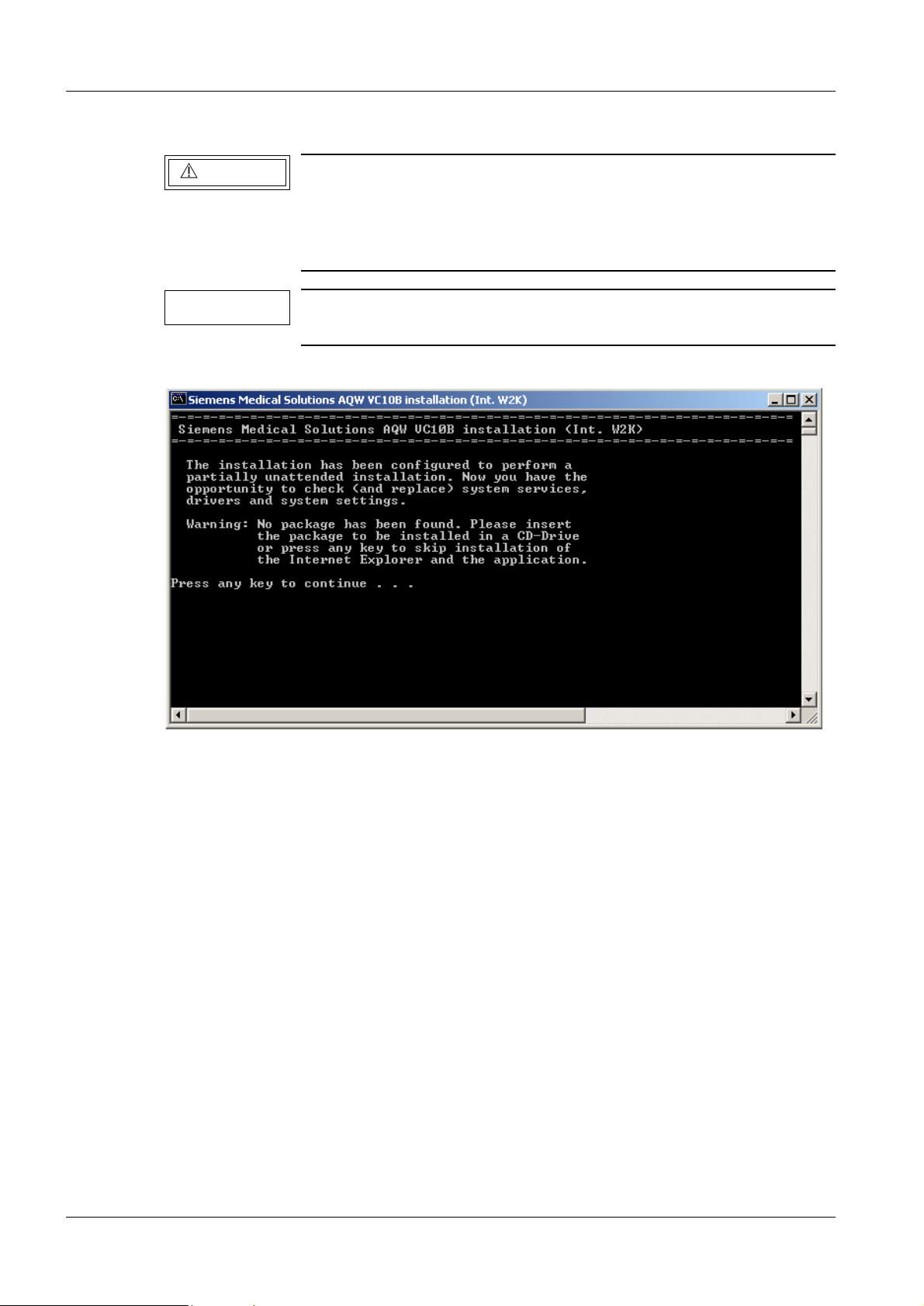
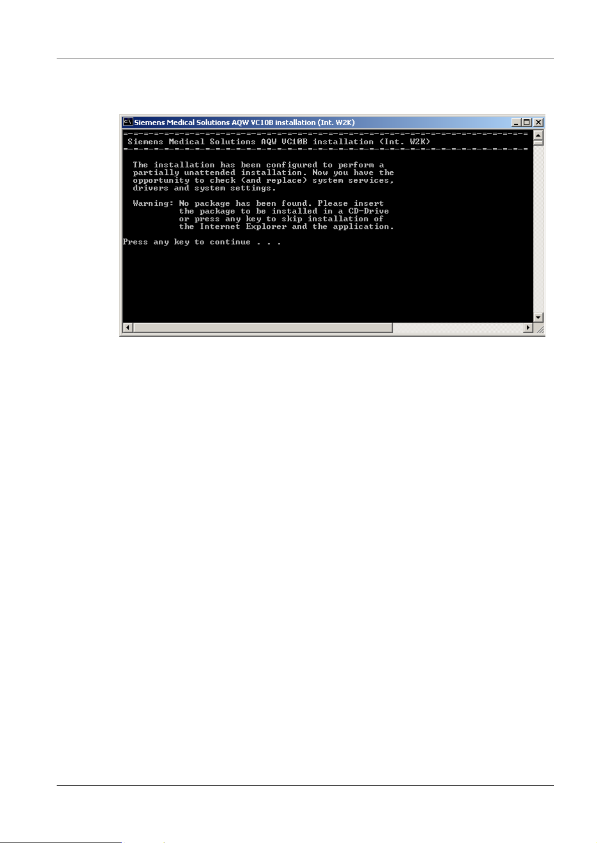
During the further installation procedure, the following DOS window appears.
Under NO circumstances should any key be pressed or any window closed. Leave the window open or minimize it. The following
settings must fir s t be made.
Any warnings that appear during the installation (e.g. "Cannot
open: C:\ASCR\log\RunOncePerUser.log") should be closed.
• Press Start to get the Windowsr 2000 menu bar.
• Select Settings > Network and Dial-up Connections.
• Right-click Net work Connection #1, select Internet Protocol (TCP/IP) and then
Properties.
• Click on Properties.
• Do the network settings for connection to the image reader.
IP: 192.168.1.1
SUBNET mask: 255.255.255.0
• Confirm with OK.
• Right-click Net work Connection #2, select Internet Protocol (TCP/IP) and then
Properties.
• Click on Properties.
• Do the network settings for the Network (the data shoul d be obtained from the site
administrator or the Planning Guide Check list).
• Close the Network and Dial-up Connections window.
DIGISCAN M Register 5 SPB7-420.816.01 Page 4 of 10 Siemens-Elema AB
System Manual Rev. 04 02.03 SPS-UD Solna, Sweden
Page 17
Software installation if no pre-installed ASCRx 3 - 5
• Insert the ASCRx software CD-ROM in the CD-RW drive.
• Return to the DOS window and activate this window.
• To do this, it may be necessary to click on a location in t he window.
• Press any key to continue with the installat ion procedure.
This is followed by a number of auto installation and boot routines.
Waiting time: approx. 30 min.
• Remove the CD-ROM.
• The AWS software installation is now done. Continue by fol lowing the next step.
• Install the license key, from the license CD-ROM, in:
C:\ASCR\config\Licensing
and rename it “license.dat”.
• If the message “This folder already contai ns a file named ‘license.dat’. ..” appears,
confirm replacement with Yes.
Siemens-Elema AB Register 5 SPB7-420.816.01 Page 5 of 10 DIGISCAN M
Solna, Sweden Rev. 04 02.03 SPS-UD System Manual
Page 18

3 - 6 Software installation if no pre-installed ASCRx
• This step only for SIMOMED monitor:
NOTICE
The monitor cable shall be connected to the r ight connector on the graphics adapter.
Boot Windows 2000.
Use F8 to stop boot and enter advanced troubleshoot ing options.
Select: Enable VGA mode.
Continue boot.
Log in as administrator.
Insert the WINDRIVER CD and browse to find the win2k\MdXPCI di rectory.
Double click setup.exe.
During installation selec t: One display and Yes when the message “I want to restart my
computer now” appears.
Log in as administrator.
Right click the desktop and select Properties > Settings.
Select Advanced > Adapter > List all modes button.
Select 1280 by 1024, 256 colors, 75 Hertz.
Select Apply and then OK .
For correct display on the SIMOMED monitor it is necessary that
the VIDEO BNC cable is correctly connected. The H signal is colored black and the V signal is colored white. The green cable is
used for the video signal.
Right click the desktop and select Properties > Settings > Advanced.
Select the DOME tab.
Set: Resolution 1280 x 1024 x 8
Refresh rate to 75 H z
Pedestal
Single channel grayscale
Dynamic gray palette
Click Apply and then Close.
Select Yes to restart the computer.
DIGISCAN M Register 5 SPB7-420.816.01 Page 6 of 10 Siemens-Elema AB
System Manual Rev. 04 02.03 SPS-UD Solna, Sweden
Page 19
Software installation if no pre-installed ASCRx 3 - 7
Manual settings 3
The following settings should be performed manually.
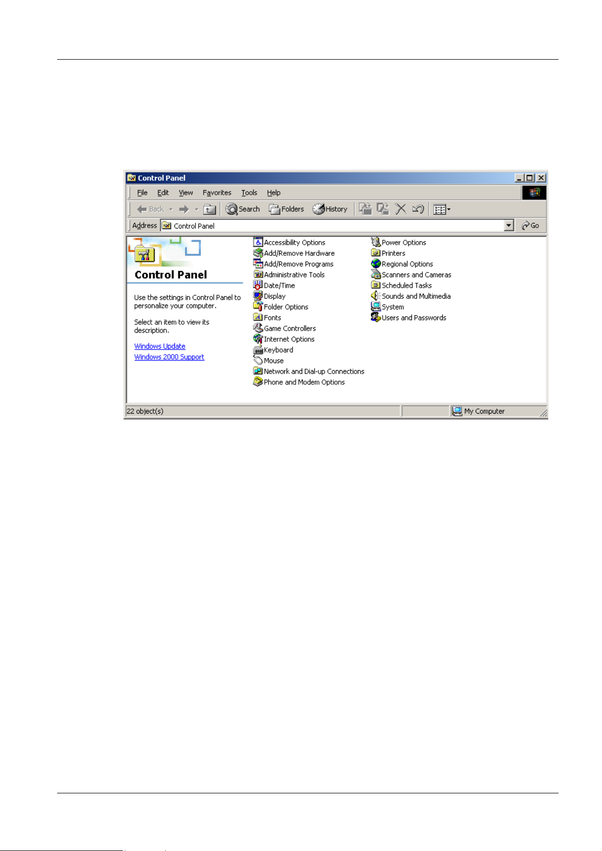
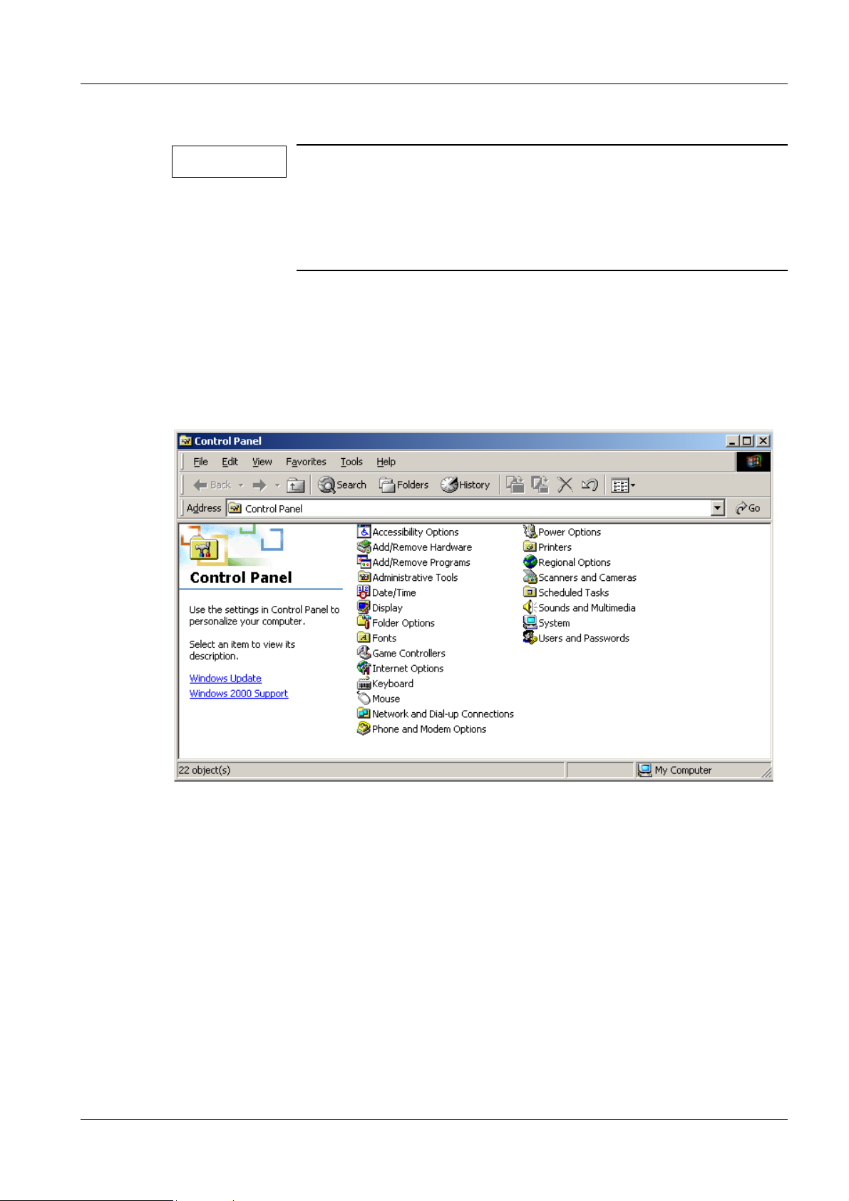
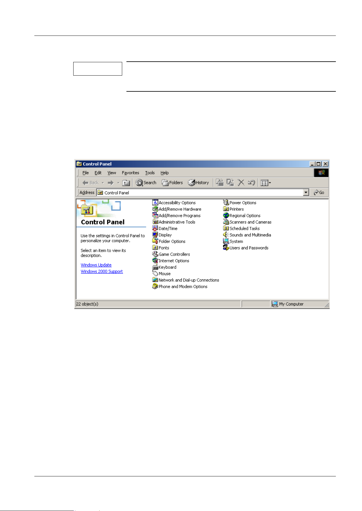
• Press Start.
• Select Settings > Control Panel.
Siemens-Elema AB Register 5 SPB7-420.816.01 Page 7 of 10 DIGISCAN M
Solna, Sweden Rev. 04 02.03 SPS-UD System Manual
Page 20
3 - 8 Software installation if no pre-installed ASCRx
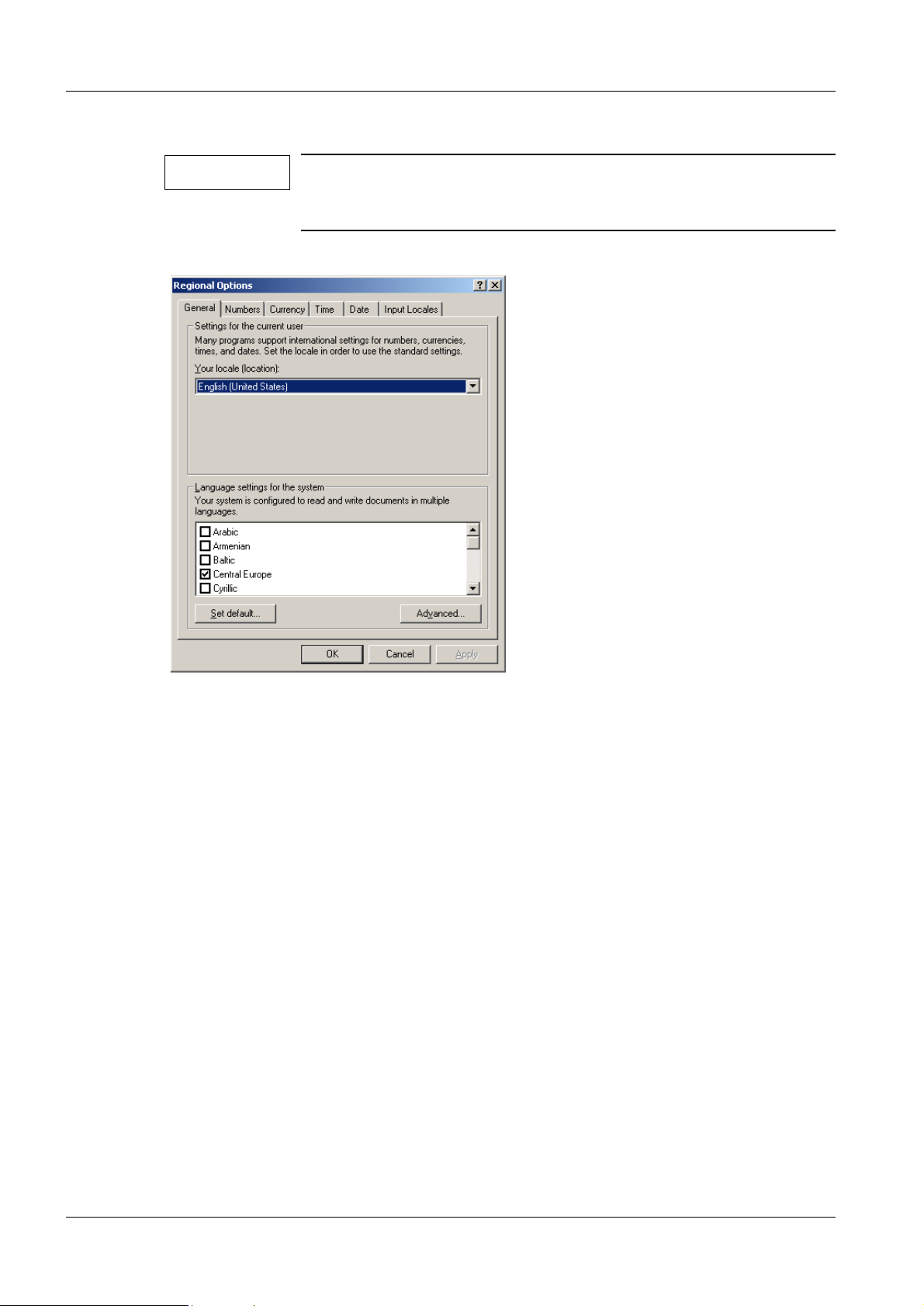
Setting of the desired user interface language (not necessary for English) 3
NOTE
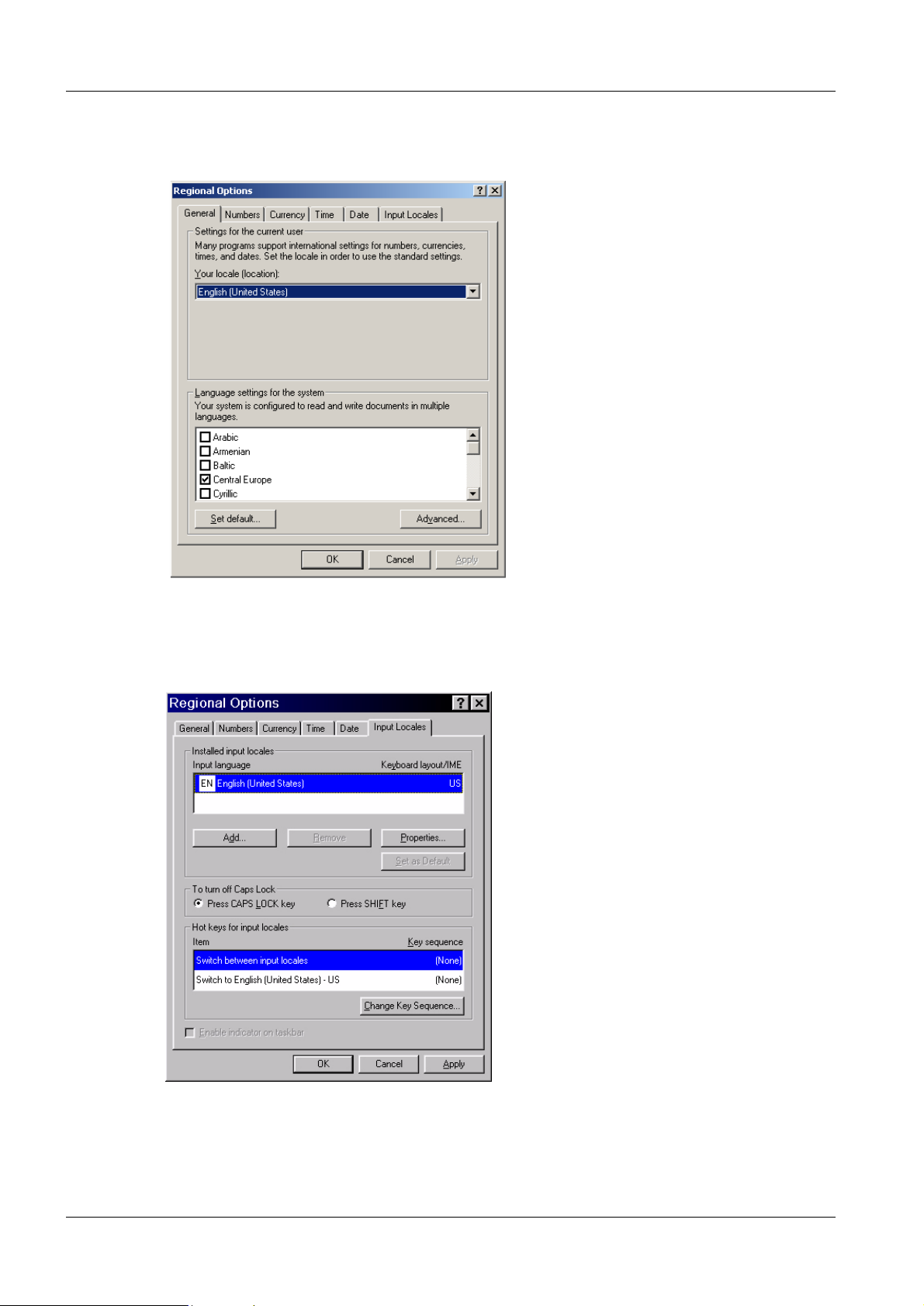
The following instructions are for regional settings in Windowsr
2000 only. For regional settings in Syngo, see Chapter Defining
the regional settings, in the Syngo Operator Manual.
• Select Regional Options in the Control Panel .
• Select the desired language here and confirm with OK.
DIGISCAN M Register 5 SPB7-420.816.01 Page 8 of 10 Siemens-Elema AB
System Manual Rev. 04 02.03 SPS-UD Solna, Sweden
Page 21
Software installation if no pre-installed ASCRx 3 - 9
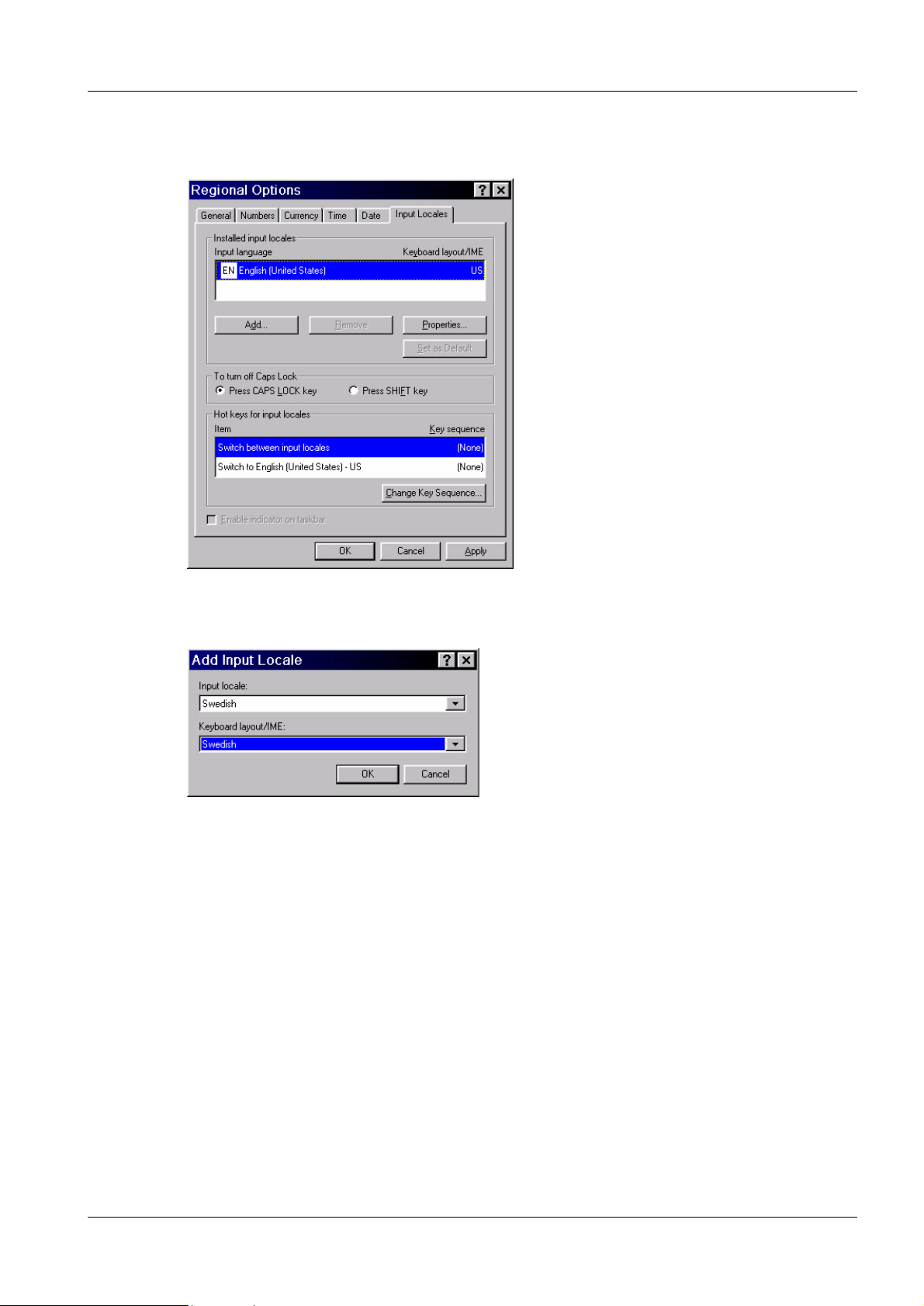
Setting the country-specific keyboard layout (only for non US-keyboard) 3
• Select Input Loca les.
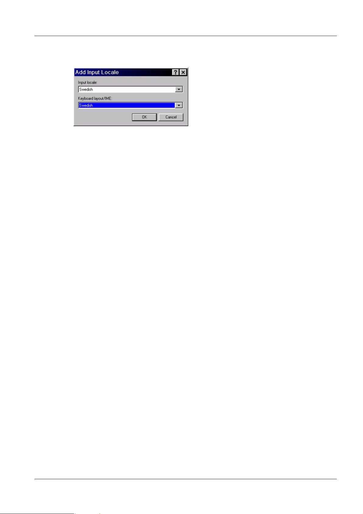
• If wanted Input Locale is missing, press Add. Select Input locale and Keyboard layout/
IME and press OK.
• Double-click on one selection in Input Locales.
• Select the layout that corresponds to the keyb oard that has been shipped in Keyboard
layout.
• Click on OK.
• Select Set as Defaul t.
• Click on Apply.
• Plug in the network cable.
• Plug in the MOD drive (option).
• Restart the acquisition workstation.
Siemens-Elema AB Register 5 SPB7-420.816.01 Page 9 of 10 DIGISCAN M
Solna, Sweden Rev. 04 02.03 SPS-UD System Manual
Page 22

3 - 10 Software installation if no pre-installed ASCRx
BIOS settings 3
During installation, the computer shall boot from the CD-RW (initial setting of the computer). After installation the computer shall boot from the hard disk.
Change BIOS settings:
• Restart the acquisition works tation.
• During the boot routine, press F2 to get into the SCSI-BI OS.
• Select Main > Boot options > Boot sequence.
• Select “Adaptec CDROM drive” and press <space> to add “!” before “Adaptec
CDROM drive”.
• Select “+Diskette” and press <space> to add “!” befor e “+Diskette”.
• Save settings.
Continue with "Syngo configuration" on Page 5 - 1.
DIGISCAN M Register 5 SPB7-420.816.01 Page 10 of 10 Siemens-Elema AB
System Manual Rev. 04 02.03 SPS-UD Solna, Sweden
Page 23
Software configuration if pre-installed ASCRx 4
General remarks 4
4 - 1
NOTE
Perform this chapter ONLY if correct version of ASCRx is preinstalled at the factory. Please check the label on the packag e box
for the same software version as your software package.
With correct pre-installed acquisition workstat ion continue with
this Chapter 4. Otherwise ignore this chapter and start with Chapter 5.
Manual settings 4
• Switch the acquisition workstation ON.
• Press Start.
• Select Settings > Control Panel.
Siemens-Elema AB Register 5 SPB7-420.816.01 Page 1 of 4 DIGISCAN M
Solna, Sweden Rev. 04 02.03 SPS-UD System Manual
Page 24
4 - 2 Software configuration if pre-installed ASCRx
Setting of the desired user interface language (not necessary for English) 4
• Select Regional Options in the Control Panel.
• Select the desired language here and confirm with OK.
Setting the country-specific keyboard layout (only for non US-keyboard) 4
• Select Input Locales.
DIGISCAN M Register 5 SPB7-420.816.01 Page 2 of 4 Siemens-Elema AB
System Manual Rev. 04 02.03 SPS-UD Solna, Sweden
Page 25
Software configuration if pre-installed ASCRx 4 - 3
• If wanted Input Locale is missing, press Add. Select Input locale and Keyboard layout/
IME and press OK.
• Double-click on one selection in Input Locales.
• Select the layout that corresponds to the keyb oard that has been shipped in Keyboard
layout.
• Click on OK.
• Select Set as Defaul t.
• Click on Apply.
• Restart the acquisition workstation.
Siemens-Elema AB Register 5 SPB7-420.816.01 Page 3 of 4 DIGISCAN M
Solna, Sweden Rev. 04 02.03 SPS-UD System Manual
Page 26

4 - 4 Software configuration if pre-installed ASCRx
This page intentionally left blank.
DIGISCAN M Register 5 SPB7-420.816.01 Page 4 of 4 Siemens-Elema AB
System Manual Rev. 04 02.03 SPS-UD Solna, Sweden
Page 27
Syngo configuration 5
General remar ks 5
5 - 1
NOTE
To assure working effectively during startup, it is necessary to
have the configuration table in the Plann ing Guide completed and
available.
Screen saver setting 5
• Log in as meduser.
• Press Start.
• Select Settings > Control Panel.
• Select Display in the Control Panel and select t he Screen Saver tab.
• Select the screen saver Marquee Display and click on Settings.
• Type “DIGISCAN M” in the text field and confirm with OK.
• Click on Apply and confi rm with OK.
• Close Control P anel.
Siemens-Elema AB Register 5 SPB7-420.816.01 Page 1 of 42 DIGISCAN M
Solna, Sweden Rev. 04 02.03 SPS-UD System Manual
Page 28
5 - 2 Syngo configuration
Configuration 5
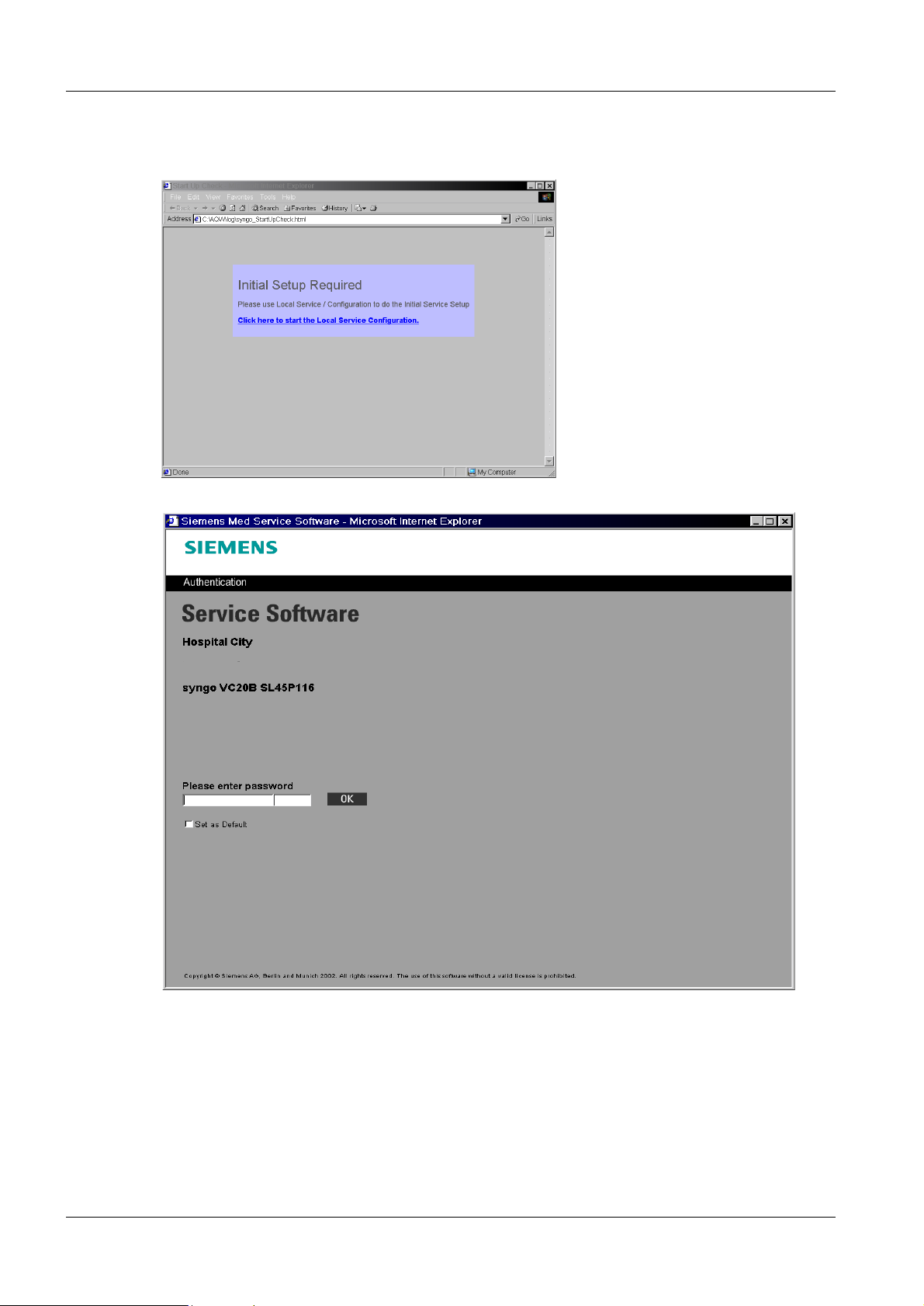
• Click to start the local service configurat ion.
• Enter the first 14 characters of the ser vice key in first mask.
• Enter the last 6 characters of the servic e key in second mask.
• Select Set as Default.
• Confirm the screen with OK.
DIGISCAN M Register 5 SPB7-420.816.01 Page 2 of 42 Siemens-Elema AB
System Manual Rev. 04 02.03 SPS-UD Solna, Sweden
Page 29
Syngo configur ation 5 - 3
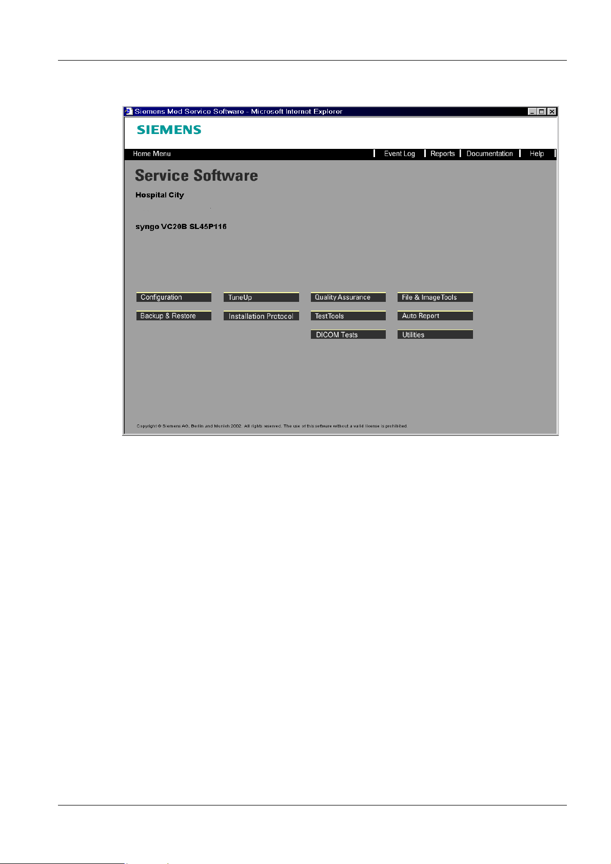
The service home menu appears.
• Select Configuration.
Siemens-Elema AB Register 5 SPB7-420.816.01 Page 3 of 42 DIGISCAN M
Solna, Sweden Rev. 04 02.03 SPS-UD System Manual
Page 30
5 - 4 Syngo configuration
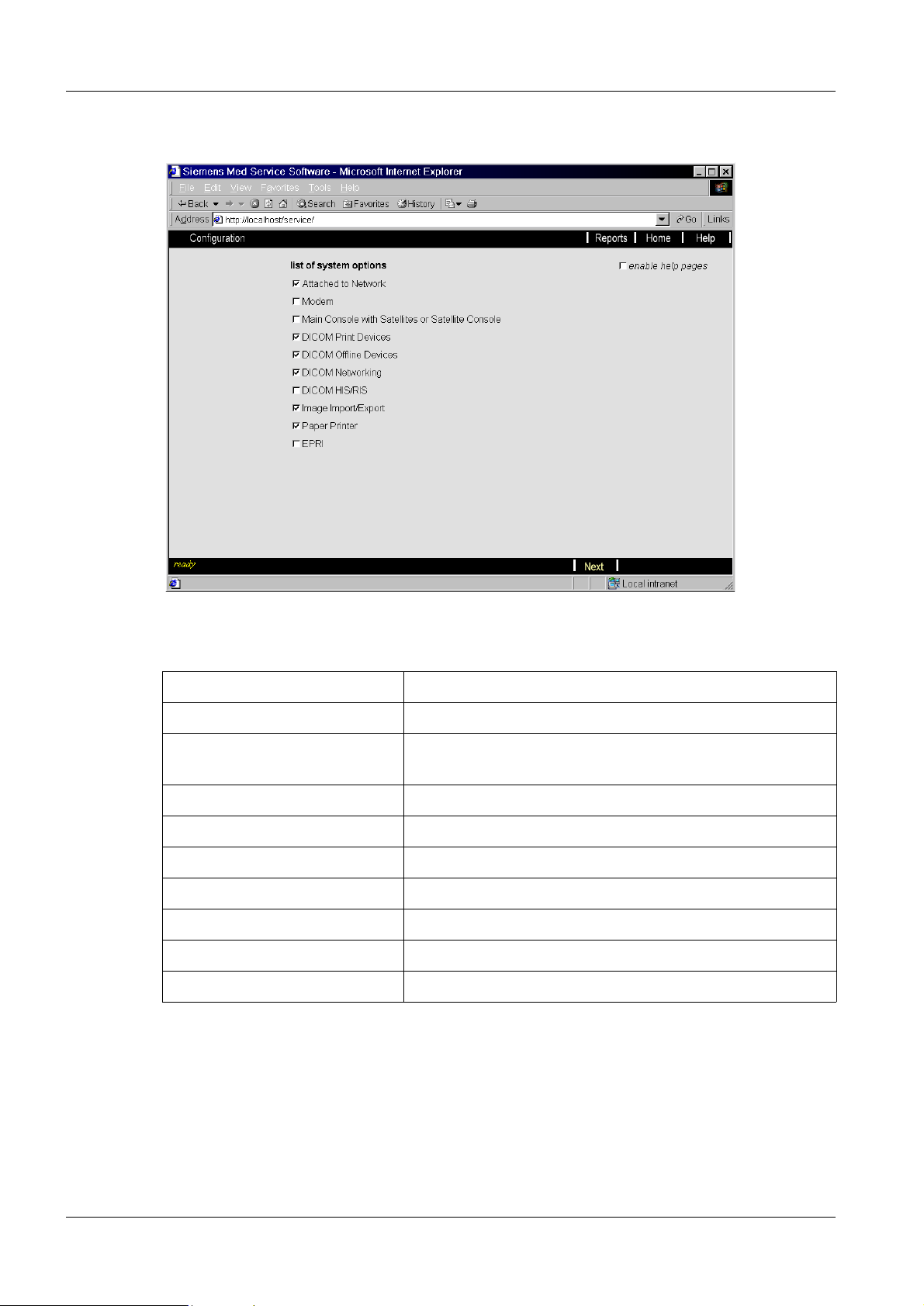
The selection menu appears.
• In the list of system options, the check boxes corresponding to the following table must
be selected accordingly.
Attached to Network If availa ble
Modem Not used
Main Console with Satell ites or
Satellite Console
DICOM Print Devices Select if a hardcopy camera is used in the network
DICOM Offline Devices Always select
DICOM Networking Always select
DICOM HIS/RIS If available
Image Import/Export Always select
Paper Printer If available
EPRI Not used
Depending on which items are select ed, differ ent points ar e listed on the l eft of th e screen
during configuration.
Not used
• In the action bar, select Next.
DIGISCAN M Register 5 SPB7-420.816.01 Page 4 of 42 Siemens-Elema AB
System Manual Rev. 04 02.03 SPS-UD Solna, Sweden
Page 31

Syngo configur ation 5 - 5
The following menu appears.
• In the action bar, select Next.
NOTE
NOTICE
During initial configuration, go through the screens in sequence
by selecting > or Next in the action bar.
With later supplements, the configu ration st eps that al ready have
entries can be skipped over. However, these program screens
must also be checked or changed to reflect the on-site conditions. The sequence of configuration steps should take place
according to the structure on the left side of the screens.
All data should be entered as described in the configur ation table.
In particular, upper and lower case conventions should be
observed!
The help text is available before each configuration screen.
Advancing to the ne xt screen is possible by selecting the > symbol in the action bar.
Additional Online Help can be obtained by pre ssing the Help button in the navigation bar.
If the configuration is exited, this must ALWAYS be done by
selecting the Finish button and then the Home button.
Siemens-Elema AB Register 5 SPB7-420.816.01 Page 5 of 42 DIGISCAN M
Solna, Sweden Rev. 04 02.03 SPS-UD System Manual
Page 32

5 - 6 Syngo configuration
NOTE
NOTE
Due to a known problem in the Syngo software an error message
(Fig. 1) will appear when the Home button is clicked. This error
message is located behind the Conf iguration window and must be
closed before the Service Home Menu will appear. To solve th is
problem move the Configuration window, locate the error message window and click the OK button to close it. The same message will appear a second time. Click OK again to close it. To
return to the Home Menu window click on the Home button in the
Configuration window.
Fig. 1 Error message window
With a pre-inst all ed acquisiti on workst ation some o f the fol lowing
screens are already filled in with data. The automatic, chronological configuration routine does not work in this case as it does
with an initial configuration. In such a case, all following screens
must therefore be selected manually.
DIGISCAN M Register 5 SPB7-420.816.01 Page 6 of 42 Siemens-Elema AB
System Manual Rev. 04 02.03 SPS-UD Solna, Sweden
Page 33

Syngo configur ation 5 - 7
Local Host 5
Site Info 5
The Site Info platform allows you to enter some general system and site-speci fic in formation for easy identification of your machine.
The next screen appears by clicking on > in the action bar.
• Fill in the boxes accordingly.
- Handed over : time at which hand over to the customer takes place.
- Seri al No: Serial number of the DIGISCAN M system. This can be found on the system
label mounted on the back of the acquisit ion workstation. If the seria l No. starts with a
“0”, this “0” should be left out .
(This entry indicates the acquisi tion workstation and is important for the function).
- Ma intenance Unit: mg
(to indicate this acquisiti on workstation as DIGISCAN M, this entry is import ant for the
function).
- Department: department.
- Sit e Identification No: Identif ication number of the system as the system is listed in
the Siemens business office.
- Servi ce Center Phone: Telephone number of the Service Support Center.
- Name: name of the customer.
- Id: enter the customer number.
- Hospital: name of the clinic/hospital .
- Street: street on which the clini c/hospital is located.
- Str eet No: address.
- Zip Code: postal code.
- Phone No: t elephone number of the clinic/hospital.
- City: name of the city/town.
Siemens-Elema AB Register 5 SPB7-420.816.01 Page 7 of 42 DIGISCAN M
Solna, Sweden Rev. 04 02.03 SPS-UD System Manual
Page 34

5 - 8 Syngo configuration
- District: name of the d istrict in which the cli nic/hospital is locat ed, corresponding to the
structure in the country organ ization.
- Country: country.
• Select Save in the action bar to save the val ues that have been entered.
• Acknowledge the message “... successfully saved” with OK.
• The next screen appears by clicking on > in the action bar.
• Update the time and date here as needed.
• Select Save in the action bar to save the val ues that were entered.
• Confirm that the time settings are OK.
• Acknowledge the message “..... successfully saved” with OK.
• Select Next in the action bar.
DIGISCAN M Register 5 SPB7-420.816.01 Page 8 of 42 Siemens-Elema AB
System Manual Rev. 04 02.03 SPS-UD Solna, Sweden
Page 35

Syngo configur ation 5 - 9
NOTICE
The following work steps describe integration of the acquisition
workstation into an e xisting network.
After finishing the complete configuration, it is necessary to configure workstations at the corresponding modalities (viewing station etc.).
The required steps are described in the instr uctions for the particular modalities.
To simplify this process, fill out the accompanying data sheet at
the end of these instructions and send it as a copy(-ies) to the
affected modalities. This pa ge contains all rele vant data to configure the acquisition workstation at these modali ties.
TCP/IP LAN Settings 5
The TCP/IP LAN platform allows y ou to configure the local networking properties of your
system. Skip this section if your system works completely as a stand-alone system, the
default values provided will do in that case.
If selected, the installat ion procedure runs automatically to the point TCP/IP LAN
are later additions and changes, manually select the poi nt in the se lection menu on the left
under Local Host.
. If there
(The Computer name box shows the entered UDB machine name.)
• Leave as it is.
NOTICE
Adapter is selected automatical l y. Do not make any changes here!
• Select Next or Finish in the action bar.
Siemens-Elema AB Register 5 SPB7-420.816.01 Page 9 of 42 DIGISCAN M
Solna, Sweden Rev. 04 02.03 SPS-UD System Manual
Page 36

5 - 10 Syngo configuration
User settings 5
The installation procedure runs automatically to the point Users. If there are any later
additions and changes, manua ll y select the point in the selection menu on the left under
Local Host.
Define the PPP password, which is used for remote login via RAS to your system. The
password needs to be kno w n at the RDIAG server.
• The log on procedure is specified in the top part of the screen. Here it i s possible to
specify whether the e xisting default pass word will be used b y syngor, whether t he user
will supply his own pass word or whether an automatic lo gin will be used. The procedure
should be discussed with the customer or wit h the responsible adminis trator (safety
aspect).
NOTE
DIGISCAN M Register 5 SPB7-420.816.01 Page 10 of 42 Siemens-Elema AB
System Manual Rev. 04 02.03 SPS-UD Solna, Sweden
Accept the settings with as few changes as possible but a given
password for administrator is preferred to the randomly
generated!
Page 37

Syngo configuration 5 - 11
If Default Password is selected the system creates the password for the Account for
UI: meduser automatically.
If Enable Autologin is selected the system starts at Autologin.
If Enable Autologin is NOT selected t he default password is necessary for login.
In the bottom part of the screen, enter t he password for Account for PPP.
This password must be the same as the password entered in the RDIAG server under
Batch Password from remote system. (A good PPP password con sists of at least 8
characters with at least one numb er, special characters (e.g. @ §$%, et c.) are not
recognized by the RDIAG server and should be avoided.)
• Select Save in th e action bar to save the values that wer e entered.
• Acknowledge the message “...successfully saved” with OK.
• Acknowledge the message “.... after reboot” with OK.
• Select Next in the action bar.
Siemens-Elema AB Register 5 SPB7-420.816.01 Page 11 of 42 DIGISCAN M
Solna, Sweden Rev. 04 02.03 SPS-UD System Manual
Page 38

5 - 12 Syngo configuration
Monitor Type 5
The configuration procedure runs auto matically to t he point Monitor Type. If there are later
additions and changes, manua ll y select the point in the selection menu on the left under
Local Host.
• If LCD monitor, make sure that color is Siemens (True Color).
If SIMOMED monitor, make sure that color is Siemens Pseudocolor.
• Select Save in the action bar to save the val ues that were entered.
DIGISCAN M Register 5 SPB7-420.816.01 Page 12 of 42 Siemens-Elema AB
System Manual Rev. 04 02.03 SPS-UD Solna, Sweden
Page 39

Syngo configuration 5 - 13
• Acknowledge the message “....successfully saved” or “...unchanged. Saving is not
necessary!” with OK.
• Select Next in the action bar.
Siemens-Elema AB Register 5 SPB7-420.816.01 Page 13 of 42 DIGISCAN M
Solna, Sweden Rev. 04 02.03 SPS-UD System Manual
Page 40

5 - 14 Syngo configuration
Security 5
NOTICE
Do not change any of the security setti ngs! The changes will lead
to a complete reinstallation of the system.
DIGISCAN M Register 5 SPB7-420.816.01 Page 14 of 42 Siemens-Elema AB
System Manual Rev. 04 02.03 SPS-UD Solna, Sweden
Page 41

Syngo configuration 5 - 15
Service 5
Mail settings 5
NOTE
The configuration procedure runs automatically to the point Mail. If there are any later
additions and changes, manually select the appropriate point in the selection menu, on
the left under Service.
The mail settings are important for the auto report function. The
needed data can be found in "Remote configuration" on Page 7 -
1.
• In Sel ect Host, select define new (with a new installation) or accept the entry (with
components that are already configured).
• In Host Name, enter the name of the target computer.
- If a name server is used, and the applicat ion exists in the network, it can be sea rched
for by using FIND.
The response should be: “Host <name> is succ essfully resolved”.
Confirm with OK. The IP addr ess will then be accepted.
- Otherwise, enter the Host Name and the IP addr ess (take the data from the
configuration table).
• Select TEST. The TEST comman d corresponds to a PING command. The response
should be: “Host with IP address xxx. xxx.xxx.xxx is alive”.
• Select connected by LAN.
Siemens-Elema AB Register 5 SPB7-420.816.01 Page 15 of 42 DIGISCAN M
Solna, Sweden Rev. 04 02.03 SPS-UD System Manual
Page 42

5 - 16 Syngo configuration
• Accept the entry with Save in the action bar.
• Acknowledge the message “...successfully saved” with OK.
• The next screen appears by clicking on > in the action bar.
• In Sel ect Logical Name, select define new.
• In Logi cal Name, enter a name.
• In Mai l Server Host Selection, select the mail serve r.
• In emai l address, enter the email address.
• Select Save in the action bar to save the val ues that were entered.
• Acknowledge the message “..... successfully saved” with OK.
• Select Next in the action bar.
DIGISCAN M Register 5 SPB7-420.816.01 Page 16 of 42 Siemens-Elema AB
System Manual Rev. 04 02.03 SPS-UD Solna, Sweden
Page 43

Syngo configuration 5 - 17
FTP settings 5
NOTE
The configuration procedure runs automatically to the point FTP. If there are later additions and changes, manually selec t the appropriat e poin t in the sel ection men u on the l eft
under Service.
The FTP settings are important for the auto report function. The
needed data can be found in chapter 7.
• In Sel ect Host, select define new (with a new installation) or accept the entry (with
components that are already configured).
• In Host Name, enter the name of the target computer.
- If a name server is used, and the applicat ion exists in the network, it can be sea rched
for by using FIND.
The response should be: “Host <name> is succ essfully resolved”.
Confirm with OK. The IP addr ess will then be accepted.
- Otherwise, enter the Host Name and the IP addr ess (take the data from the
configuration table).
• Select TEST. The TEST comman d corresponds to a PING command. The response
should be: “Host with IP address xxx. xxx.xxx.xxx is alive”.
• Select connected by LAN.
• Accept the entry with Save in the action bar.
• Acknowledge the message “...successfully saved” with OK.
Siemens-Elema AB Register 5 SPB7-420.816.01 Page 17 of 42 DIGISCAN M
Solna, Sweden Rev. 04 02.03 SPS-UD System Manual
Page 44

5 - 18 Syngo configuration
• The next screen appears by clicking on > in the action bar.
• In Sel ect Logical Name, select define new.
• In Logi cal Name, enter a name.
• In FTP Host Selection, select the FTP host.
• In FTP user , enter the user.
• In Password, enter a password.
• Select Save in the action bar to save the val ues that were entered.
• Acknowledge the message “..... successfully saved” with OK.
• Select Next in the action bar.
DIGISCAN M Register 5 SPB7-420.816.01 Page 18 of 42 Siemens-Elema AB
System Manual Rev. 04 02.03 SPS-UD Solna, Sweden
Page 45

Syngo configuration 5 - 19
Auto Transfers 5
The configuration procedure runs automatically to the point Auto Transfers. If there are
later additions and changes, manually select the appropriate point in the selection menu
on the left under Service.
• Select Activat e automatic Transfers.
• Select Save in th e footer to save the values that were ent ered.
• Acknowledge the message "...successfully saved" with OK.
• Select Finish in the action bar.
Siemens-Elema AB Register 5 SPB7-420.816.01 Page 19 of 42 DIGISCAN M
Solna, Sweden Rev. 04 02.03 SPS-UD System Manual
Page 46

5 - 20 Syngo configuration
Eventlog settings 5
The configuration procedure runs automatical ly to the point Eventlog. If there are later
additions and changes, manuall y select the appropriate point in the select ion menu on the
left under Service.
The Eventlog function allows customizing of the Event Log user interface of your Service
Software. Specify whether:
only service-relevant messages should be logged
only service-relevant messages should be displayed in the Event Log window (with all
errors being logged) and the sequence number should be displayed.
• If not otherwise specified, select all 3 check boxes.
• Select Save in the footer to save the values that were entered.
• Acknowledge the message "...successfully saved" with OK.
• Select Finish in the action bar.
• Select > or Next in the action bar until the point DICOM General.
DIGISCAN M Register 5 SPB7-420.816.01 Page 20 of 42 Siemens-Elema AB
System Manual Rev. 04 02.03 SPS-UD Solna, Sweden
Page 47

Syngo configuration 5 - 21
DICOM 5
General 5
The configuration procedure runs automatically up to the point General. If there are later
additions or changes, manually select the point in the selection menu on the l eft under
DICOM.
(The box es, shows the entered UDB machine name.)
Take the data from the configuration table. The AET names must be unique in the net-
work. They will be automatically set by changing the host name in the TCP/IP LAN settings dialog.
NOTE
Siemens-Elema AB Register 5 SPB7-420.816.01 Page 21 of 42 DIGISCAN M
Solna, Sweden Rev. 04 02.03 SPS-UD System Manual
Keep Host name!
Page 48

5 - 22 Syngo configuration
NOTICE
The Print AET is required to distinguish between the different
modalities sending images to the printer to select the proper LUT
accordingly.
If the wrong AET is configured a default LUT
the printer, which has a big impact on the image quality!!!
• Select Save in the action bar to save the values th at were entered.
• Acknowledge the message “...successfully saved” with OK.
• The next screen appears by clicking on > in the action bar.
might be selected in
• Select Next in the action bar.
DIGISCAN M Register 5 SPB7-420.816.01 Page 22 of 42 Siemens-Elema AB
System Manual Rev. 04 02.03 SPS-UD Solna, Sweden
Page 49

Syngo configuration 5 - 23
Character settings 5
The configuration proced ure runs automatically up to the point Character Set. If there are
later additions or changes, manually select the point in the selection menu on the left
under DICOM.
The settings need to be changed only if the keyboard allows this option.
ISO 2022 IR 6 ASCII
ISO2022 IR 100
ISO2022 IR 13
Latin1 <recommended>
Japan
• If changed, select Save in the action bar to save the val ues that have been entered and
acknowledge the message “...successfully saved ” with OK.
• Select Next in the action bar.
Siemens-Elema AB Register 5 SPB7-420.816.01 Page 23 of 42 DIGISCAN M
Solna, Sweden Rev. 04 02.03 SPS-UD System Manual
5
Page 50

5 - 24 Syngo configuration
Offline Device settings 5
When selected, the configuration procedure runs automatically up to the point Offline
Devices. If there are later additions or changes, manually select the point in the selecti on
menu on the left under DICOM.
In this section, you define the setting of DICOM offline devices on the local host.
• Enter a logical name for the offline devi ces (e.g. CD-RW or MOD).
• If it is an archive device, sele ct it.
• Select the drive type.
NOTE
Do not select Floppy as archive devices.
• Select a drive letter, if more than one devi ce of the same type is available on t he local
host.
• Select Save in the action bar to save the values th at were entered.
• Acknowledge the message “...successfully saved” with OK.
• Repeat this procedure for all devices (CD-RW, MOD).
• Select Next in the action bar.
DIGISCAN M Register 5 SPB7-420.816.01 Page 24 of 42 Siemens-Elema AB
System Manual Rev. 04 02.03 SPS-UD Solna, Sweden
Page 51

Syngo configuration 5 - 25
Network Node settings 5
When selected, the procedure runs automatically up to the point Network Nodes. If there
are later additions and changes, manually select the poi nt in the se lection menu on the left
under DICOM.
NOTE
Network nodes are acquisiti on workstations, viewing stat ions and
hospital archive systems.
Definition of network nodes which are connected to the acquisition wo rkstat ion.
• In Sel ect Host, select define new (with a new installation) or accept the entry (with
components that are already configured).
• In Host Name, enter the name of the 1st application (e.g. viewing station).
- If a name server is used, and the 1st appli cation is configured in the network, it can be
searched for by using FIND.
The response should be: “Host <name> is succ essfully resolved”.
Confirm with OK. The IP addr ess will then be accepted.
- Otherwise, enter the Host Name and the IP addr ess (take the data from the
configuration table).
• Select TEST. The TEST comman d corresponds to a PING command. The response
should be: “Host with IP address xxx. xxx.xxx.xxx is alive”.
• Select connected by LAN.
Siemens-Elema AB Register 5 SPB7-420.816.01 Page 25 of 42 DIGISCAN M
Solna, Sweden Rev. 04 02.03 SPS-UD System Manual
Page 52

5 - 26 Syngo configuration
• Accept the entry with Save in the action bar.
• Acknowledge the message “...successfully saved” with OK.
• Repeat the steps described above until all network nodes ar e entered.
• The next screen appears by clicking on > in the action bar.
NOTE
DIGISCAN M Register 5 SPB7-420.816.01 Page 26 of 42 Siemens-Elema AB
System Manual Rev. 04 02.03 SPS-UD Solna, Sweden
Veri fication is on ly possib le after Sa ve! (Might w ork onl y when the
other node has configured the acquisition workstation.)
Page 53

Syngo configuration 5 - 27
The remaining data for the previously entered host(s) are sup plemented here.
NOTICE
Here, only stations and systems should be entered that support
the services: Storage SCP or Query/Retri eve or if there are syngo
based stations.
Stations that use ONLY Storage SCU do not need to be entered.
Transmitting from these stations to the acquisition workst ati on is
still possible.
If stations with ONLY Storage SCU at the network nodes are
entered, these appear inco rrectly i n the user inter face in the list of
transmit destinations.
• At Logical name, select define new or accept the entry.
• At edit Name, enter the name f or the application as it is to be displ ayed later on the user
interface (e.g. viewing stati on).
• Select Syngo base d if this application is syngo based.
• In Host, select the network node.
• In AE Title , if already configured, s elect the AE Title or enter the AE Title (e.g. AE Title of
the viewing station) and Port Number of the ap plication (e.g. 50082) (tak e the
information from the configura tion table).
• In Def ault Node, select the default. Th e sequence first default, second default or no
default is set. This sett ing is defined as which application is to be selected as the default.
• Only formats supported by the stations (e .g. Implicit little endian. ..) should be selected,
i.e. highlighted in blue.
Select Compression only if the other stati on supports Compression. In case of doubt
look up or try out in the DICOM Conformance Stateme nt!
NOTICE
NOTE
NOTE
If transfer syntax JPEG lossless should be used for sending
images to a non syngo based netw ork destination this destina tion
must be configured as syngo based. Otherwise o verlay graphics
won’t be transmitted.
Do not use JPEG Lossy Compression!
There are more than one AE Title in one host selection possible.
(e.g. one for Image Transfer and one for QUERY and RETRIEVE.)
• Select Save in th e action bar to save the values that wer e entered.
• Acknowledge the message “...successfully saved” with OK.
Siemens-Elema AB Register 5 SPB7-420.816.01 Page 27 of 42 DIGISCAN M
Solna, Sweden Rev. 04 02.03 SPS-UD System Manual
Page 54

5 - 28 Syngo configuration
The connection can be tested using the Verification button. The TEST command corre-
sponds to a C-Echo command. If the test is successful, the message “...is responsing”
appears.
If there are different AETs defined for Stor age, Query and Retrieve for individual modali ties, they should each be entered with a new entry with different logical names.
• Repeat this procedure until all network components , even for different AE titles, have
been entered.
• Select Next or Finish in the action bar.
DIGISCAN M Register 5 SPB7-420.816.01 Page 28 of 42 Siemens-Elema AB
System Manual Rev. 04 02.03 SPS-UD Solna, Sweden
Page 55

Syngo configuration 5 - 29
Print Device settings (option) 5
If selected, the configuration procedure runs automatically to the point Print Dev ices. If
there are later additions and changes, manually select the point on the left under DICOM.
Configuration of hardcopy devices. Here you define the laser camer as and printers that
are connected to your system. The example below describes the configuration for a
Fuji FM DP-L.
• At Sel ect Host, select define new or the configur ed camera.
• In Host Name, accept <network name> or enter a name.
- If a name server is used and the applica tion is configured in the network, it can be
searched for using FIND.
The response should be: “Host <name> is successfully resolved”.
Confirm with OK. The IP addr ess will then be accepted.
- Otherwise, enter the Host name and the IP addr ess (take the data from the
configuration table).
• Using the Test button, attempt to rea ch the network component just configur ed. The
TEST command corresponds to a PING command.
If the test is successful , the message “...is alive” appears.
If the test is not successful , the message “...is not alive” appears.
A comparison of the entries for the net work components and those that have been
completed must then be made.
• Select connected by LAN.
• Select Save in th e action bar to save the values that wer e entered.
Siemens-Elema AB Register 5 SPB7-420.816.01 Page 29 of 42 DIGISCAN M
Solna, Sweden Rev. 04 02.03 SPS-UD System Manual
Page 56

5 - 30 Syngo configuration
• Acknowledge the message “...successfully saved” with OK.
• Repeat the procedure until all cameras being used are entered .
• The next screen appears by clicking on > in the action bar.
Here, the remaining data for the previously entered host(s) is supplemented. Take the
information from the configuration table.
• In Logi cal Name select define new or accept the entr y.
• In edi t Name enter the name for the hardcopy camera (e.g. Fuj iFilm01).
• In Host, select the corresponding name of t he hardcopy camera (e.g. FujiFilm01).
• In AE Ti tle, if already configured, sele ct the AE title (e.g.Fujif ilm01) or select define new.
• Accept the Port Number or enter one (e.g.104).
• Using the Verification button, attempt to reach the network component just configured.
The Verification command corresponds to a C-Echo c ommand.
If the test is successful, the message “...is responding” appears.
If the test is not successful , the message “...is not responding” appears.
A comparison of the entries for the ne twork components and the entries that hav e been
made is then necessary.
• Select Save in the action bar to save the val ues that were entered.
• Acknowledge the message “...successfully saved” with OK.
• Repeat the procedure as often as required until all har dcopy cameras being used are
configured.
DIGISCAN M Register 5 SPB7-420.816.01 Page 30 of 42 Siemens-Elema AB
System Manual Rev. 04 02.03 SPS-UD Solna, Sweden
Page 57

Syngo configuration 5 - 31
• The next screen appears by clicking on > in the action bar.
Below, hardcopy camera data for i.e. Fuji FM DP-L small image s (18x24 cm) and large
images (24x30 cm) is entered.
• At Sel ect HC Device, sel ect define new and enter the name for hardc opy camera as it
will be displayed later on the user interface (e.g. Fuji_small).
• In Type select DICOM printer.
• In Class select the hardcopy camera name (e.g. fujifmdpl HiRes).
• In DICOM Node select the configured hardcopy camera (e.g. Fu jiFilm01).
• In Fi lm Sheet Formats Portrait, select Inch11x14 and press the Del button.
• Select define new and enter Inch11x14 at Film Sheet Format.
• In Number of Pixel, enter 3540 in cols and 4740 in rows.
• Select Add.
• In Medi um type select the used medium.
NOTICE
At Film Sheet Formats it might be necessary to select and delete
the formats, which are not used!
• At Fi lm destination select the used destination.
• Select Save in th e action bar to save the values that wer e entered.
• Acknowledge the message “...successfully saved” with OK.
Siemens-Elema AB Register 5 SPB7-420.816.01 Page 31 of 42 DIGISCAN M
Solna, Sweden Rev. 04 02.03 SPS-UD System Manual
Page 58

5 - 32 Syngo configuration
• Repeat this procedure for large images e.g with the name Fuji _large.
The Film Sheet Format is still Inch11x1 4. In Number of Pixel, enter 4728 in cols and
5928 in rows.
• Repeat the procedure as often as required until all camer as being used are configured.
• Select Finish in the action bar.
DIGISCAN M Register 5 SPB7-420.816.01 Page 32 of 42 Siemens-Elema AB
System Manual Rev. 04 02.03 SPS-UD Solna, Sweden
Page 59

Syngo configuration 5 - 33
Hardcopy Overview 5
When selected, the configuration procedure runs automatically up to the point HC Overview. If there are later additions or changes, manually sele ct the point in the selection
menu on the left under DICOM.
Here, modification and test capability of the previously entered data is done
• Using the Test button, attempt to rea ch the network component just configur ed. The
network access TEST command corresponds to a PING command.
The DICOM access TEST command corresponds to a C-Echo command.
• Select Save in th e action bar to save the values that wer e entered.
• Acknowledge the message “...successfully saved” with OK.
• Select Next in the action bar.
Siemens-Elema AB Register 5 SPB7-420.816.01 Page 33 of 42 DIGISCAN M
Solna, Sweden Rev. 04 02.03 SPS-UD System Manual
Page 60

5 - 34 Syngo configuration
LUT File settings 5
When hardcopy camera is selected, the configuration procedure runs automatically up to
the point LUT files
selection menu on the left under DICOM.
. If there are later additi ons or changes, manually select the point in the
• Leave as it is.
• The next screen appears by clicking on > in the action bar.
DIGISCAN M Register 5 SPB7-420.816.01 Page 34 of 42 Siemens-Elema AB
System Manual Rev. 04 02.03 SPS-UD Solna, Sweden
Page 61

Syngo configuration 5 - 35
• Select the LUTs for the following image types:
Image type LUT Max Density
CRImage
SCImage
XAImage
XRFImage
XABiPlaneImage
DXMGImage
cr
sc 3.00
xa 3.00
xrf 3.00
xabipl 3.00
cr 3.00
3.00
• Select Save in th e action bar to save the values that wer e entered.
• Acknowledge the message “...successfully saved” with OK.
• Select Next or Finish in the action bar.
Siemens-Elema AB Register 5 SPB7-420.816.01 Page 35 of 42 DIGISCAN M
Solna, Sweden Rev. 04 02.03 SPS-UD System Manual
Page 62

5 - 36 Syngo configuration
HIS / RIS Node settings 5
If selected, the configuration procedure runs automatically up to the point HIS /RIS
Nodes. If there are later additions or changes, manually select the point in the selection
menu on the left under DICOM.
• In Sel ect Host, select define new (with a new installation) or ac cept the entry (with
components that are already configur ed).
• In Host Name, enter the name of the HIS/RIS node (e.g. HISRIS ).
- If a name server is used, and the HIS/RIS is co nfigured in the network, it can be
searched for by using FIND.
The response should be: “Host <name> is suc cessfully resolved”.
Confirm with OK. The IP address will then be acce pted.
- Otherwise, enter the Host Name and the IP address ( take the data from the
configuration table).
• Select TEST. The TEST command corresponds to a PING command. The response
should be: “Host with IP address xxx. xxx.xxx.xxx is alive”.
• Select connected by LAN.
• Accept the entry with Save in the action bar.
• Acknowledge the message “...successfully saved” with OK.
• The next screen appears by clicking on > in the action bar.
DIGISCAN M Register 5 SPB7-420.816.01 Page 36 of 42 Siemens-Elema AB
System Manual Rev. 04 02.03 SPS-UD Solna, Sweden
Page 63

Syngo configuration 5 - 37
• In Logi cal Name select define new or accept the entry.
• In edi t Name enter the name for the HIS/RIS (e.g. HISRIS).
• In Host, select the corresponding name of th e HIS/RIS node (e.g. hisris).
• In AE Tit le, if already configured, select the AE t itle or select define new.
• Accept the Port Number or enter one (e.g. 104).
• Using the Verification button, att empt to reach the network component just configured.
The Verification command corresponds to a C-Echo co mmand.
If the test is successful, the message “...is responding ” appears.
If the test is not successful , the message “...is not responding” appears.
A comparison of the entries for the net work components and the entries that have been
made is then necessary.
• Select Basic Wor klist.
• Select Default Basic Worklist Node.
• Select Save in th e action bar to save the values that wer e entered.
• Acknowledge the message “...successfully saved” with OK.
• Select Finish in the action bar.
Siemens-Elema AB Register 5 SPB7-420.816.01 Page 37 of 42 DIGISCAN M
Solna, Sweden Rev. 04 02.03 SPS-UD System Manual
Page 64

5 - 38 Syngo configuration
Import / Export 5
Directory Settings 5
If selected, the configuration procedure runs automatically up to the point Directories. If
there are later additions or changes, manually select the point in the selection menu on
the left under Import/Export.
The directories function enables the location of the image import/export directory, i.e. the
location named by your customer for importing/exporting patient images, to be specified.
This import/export directory may be located on the local system or on a remote system on
the network.
NOTE
If the directory is not located on a remote system, cli ck on > in the
action bar.
• At Sel ect Host select define new or the existing Host.
• In Host Name enter network name or accept the name.
- If a name server is used and the applicati on is configured in the network, it can be
searched for using FIND.
The response should be “Host <name> is successfully resolved”.
Confirm with OK. The IP address is accepted.
- Otherwise, enter the Host Name and the IP address ( take the data from the
configuration table).
• Using the Test button, attempt to reach the networ k component just configured. The
TEST command corresponds to a PING command.
If the test is successful , the message “...is alive” appears.
DIGISCAN M Register 5 SPB7-420.816.01 Page 38 of 42 Siemens-Elema AB
System Manual Rev. 04 02.03 SPS-UD Solna, Sweden
Page 65

Syngo configuration 5 - 39
If the test is not successful , the message “...is not alive” appears.
A comparison of the entries in the net work components and the entries made must then
be made.
• Select connected by LAN.
• Select Save in th e action bar to save the values that wer e entered.
• Acknowledge the message “...successfully saved” with OK.
• Repeat the procedure until all hosts have been entered.
• The next screen appears by clicking on > in the action bar.
Here, it is defined whether the import/export directory is connected locally or through the
network.
NOTE
The default directory C:\ temp exists already!
• Under Logi cal Name, enter a name for this machine.
• Select Local syst em or Remote System.
• At Local system, select the drive and enter the path . If the path does not exist, it can be
entered and can be created using the create button.
• At Remote syst em, select the Host using the drop-down menu, or enter Share.
• Select Save in th e action bar to save the values that wer e entered.
• Acknowledge the message “...successfully saved” with OK.
• Select Next or Finish in the action bar.
Siemens-Elema AB Register 5 SPB7-420.816.01 Page 39 of 42 DIGISCAN M
Solna, Sweden Rev. 04 02.03 SPS-UD System Manual
Page 66

5 - 40 Syngo configuration
External devices 5
Paper Printer settings 5
If selected, the confi gura ti on procedur e runs automati cally up to t he poi nt Paper Printer. If
there are later additions or changes, manually select the point in the selection menu on
the left under External de vices.
• Select available media formats.
• Select Save in the action bar to save the val ues that were entered.
• Acknowledge the message “...successfully saved” with OK.
• Select Next in the action bar.
DIGISCAN M Register 5 SPB7-420.816.01 Page 40 of 42 Siemens-Elema AB
System Manual Rev. 04 02.03 SPS-UD Solna, Sweden
Page 67

Syngo configuration 5 - 41
Applications 5
• Select > or Next until all points listed in the l eft of the screen are yellow.
• Select Finish.
• Select Home in th e navigation bar.
• Acknowledge the message “...reboot is necessary” with OK.
• Perform a backup according to "Backup / Restore" on Page 8 - 1.
• Proceed with chapter 7 if remote access is available or wi th chapter 2 - 1 of the Start-up
instructions.
Siemens-Elema AB Register 5 SPB7-420.816.01 Page 41 of 42 DIGISCAN M
Solna, Sweden Rev. 04 02.03 SPS-UD System Manual
Page 68

5 - 42 Syngo configuration
This page intentionally left blank.
DIGISCAN M Register 5 SPB7-420.816.01 Page 42 of 42 Siemens-Elema AB
System Manual Rev. 04 02.03 SPS-UD Solna, Sweden
Page 69

Image Processing 6
6 - 1
NOTE
This chapter is not applicab le during an installation.
• In Home Menu Se lect Qualit y Assurance.
• In Source select Image Processing.
Siemens-Elema AB Register 5 SPB7-420.816.01 Page 1 of 12 DIGISCAN M
Solna, Sweden Rev. 04 02.03 SPS-UD System Manual
Page 70

6 - 2 Image Processing
• In Action select Parameter Settings.
• The Image Pro cessing Parameter Window appears.
DIGISCAN M Register 5 SPB7-420.816.01 Page 2 of 12 Siemens-Elema AB
System Manual Rev. 04 02.03 SPS-UD Solna, Sweden
Page 71

Image Processing 6 - 3
3
Image Processing Parameter Settings 6
In the Image Processing Parameter Window can Image Processing parameters be tuned
by the CSE. By pressing reset, par ameter s will be set to a validated set of parameters. To
be able to modify image processing the different parameters has to be explained.
DIGISCAN M will use an image processing softw are MFP (Multi- Objectiv e Frequency Processing) from Fuji Photo Film Co., Ltd.
The controlling parameters can be divided in three groups:
• Gradation Processing
• Multi-Objective Frequency Processing (MFP)
• Dynamic Range Control (DRC)
EDR in reader Prersentation
Fig. 1
MFP + DRC
Gradation Processing
FFDM0060
Gradation Processing 6
Gradation processing is performed to convert the digital input data to an image with
appropriate density and contrast.
The gradation process is controlled by the following four parameters:
• GT (gradation type)
A curve providing gradation. Two curves for Mammography are provided.
• GA (rotation amount)
Parameter for varying the contrast.
γ = γ(GT) x GA Th e γ v alue det ermined by GT is multi plied b y GA to obtain the
final
γ value.
• GC (rotation center)
Density center for rotation. The density at the rotation center remains
unchanged even when the GA changes.
• GS (density shift)
Paramete r for c hangi ng the density. Density change amount when GA = 1.0 f or
linear gradation.
Siemens-Elema AB Register 5 SPB7-420.816.01 Page 3 of 12 DIGISCAN M
Solna, Sweden Rev. 04 02.03 SPS-UD System Manual
Page 72

6 - 4 Image Processing
4
Fig. 2
Gradation process adjustment procedure 6
Most adjustment can be made by v arying the GA and GS parameters . If such adjus tments
do not help, you should reassess the GT parameter. (There is no need to vary the GC
parameter.)
First, vary the GS param eter so as to obtain the proper density
Next vary the GA parameter so as to obtain the proper contrast.
If, for instance, GA = 1.2 the resulting contrast is 1.2 times higher then exhibited when
GA = 1.0.
Provided GT curves
3,0
2,5
2,0
1,5
Density
1,0
0,5
T
Q
0,0
-0,5
Fig. 3
256 512 768 102
Digital value
DIGISCAN M Register 5 SPB7-420.816.01 Page 4 of 12 Siemens-Elema AB
System Manual Rev. 04 02.03 SPS-UD Solna, Sweden
Page 73

Image Processing 6 - 5
Multi-Objective Frequency Processing (MFP) 6
Overview 6
The multi-objectiv e frequen cy process (hereinaf ter referre d to as the MFP) w as de v eloped
intended to improve the diagnostic image quality provided by image proce ssing. This new
process depicts gray-scale shadows and shape shadows while providing natural appearing enhancements and offering a wide visibility range suitable to the diagnostic purpose.
Moreover, this process makes well-balanced enhancements to all spatial frequency components and suppresses ov ershoots that might be caused by strong signals. Further considerations are also given to this process to avoid unnaturalness.
Radiograph features 6
The MFP can make well-balanced enhancements to various structures, from large to
small ones. When used in conjunction with a gr adation process, the MFP also offers the
following features:
1. Gray-scale shadows and shape shadows can be enhanced in a wel l-balanced
manner without sacrificing the grai niness.
2. Invisible areas can be depicted with an i ncreased degree of naturalness.
3. The degree of enhancement is suppressed for meta ls and other structures
extraneous to the human body.
Principles 6
1. Process overview
The MFP has two functions: frequency enhancement f or enh ancing dot and line shadows
and DRC for controlling the image dynamic range . In the basic MFP, smoothed images
are first generated, after which the difference between each smoothed image is determined. The resulting difference-images are subjected to nonlinear conversion, and then
the sum of the converted difference-images is used to perform frequency enhancement
and DRC processes.
2. Smoothing Process and subtraction pr ocess
In the MFP's smoothing process, because wei ghting is conducted prior to smoothing, the
resulting smoothed images are more natural than tho se derived from simple averaging.
(See Fig. 4.) The frequency response shown in Fig. 5 indi cates that the response characteristic is smooth.
Siemens-Elema AB Register 5 SPB7-420.816.01 Page 5 of 12 DIGISCAN M
Solna, Sweden Rev. 04 02.03 SPS-UD System Manual
Page 74

6 - 6 Image Processing
The signal differentials between neighboring smoot hed image signals have a response
characteristic shown in Fig. 6, representing a so-called band pass signal consisting of
specific frequency components.
Fig. 4
Fig. 5 Smoothing signal response Fig. 6 Response of signal differentials between neighboring
smoothing signals.
3. Enhancement signal components
All band pass signals (signal differentials
between smoothed signals) are subjected to
nonlinear conversion, which is detailed later.
Further, they are added with their sizes
adjusted to create basic enhancement signal
components. A typical example is shown in
Fig. 7.
The enhancement frequency response can
be controlled as desired for enhancement
signal components.
Unlike the conv e ntional frequency pr ocess, a
smooth response characteristic is obtained,
Fig. 7 Spatial frequency (cycles/mm)
minimizing the degree of unnaturalness
inherent in processing.
DIGISCAN M Register 5 SPB7-420.816.01 Page 6 of 12 Siemens-Elema AB
System Manual Rev. 04 02.03 SPS-UD Solna, Sweden
Page 75

Image Processing 6 - 7
4. Contrast-dependent nonlinear function conversion
If an image containing a metal or other strong signals is enhanced by the conventional
process, artifacts may be generated around the si gnal. The MFP suppresses such strong
signals, provi ding the enhanced image a natural look. With reference to Fig. 8, i f, for
instance, a band pass signal (d iffer ence-i mage sign al) having a relatively low contrast (as
indicated by (1) in th e figure) is entered in relation to the indicated nonlinear function, the
resulting output signal (1)' has the same contrast as the input signal. However, if a highcontrast signal is entered (as indicated by (2), it is converted to generate an output signal
having a lower contrast (2)' ).
When the nonlinear function is used in the frequency enhancement process, the very
small signals with low contrast are enhanced normally while the degree of enhancement
is suppressed for metal portions and other high-contrast edges.
Fig. 8 Mechanism of contrast-dependent frequency enhancement
Fig. 9 Contrast-dependent nonlinear function
Siemens-Elema AB Register 5 SPB7-420.816.01 Page 7 of 12 DIGISCAN M
Solna, Sweden Rev. 04 02.03 SPS-UD System Manual
Page 76

6 - 8 Image Processing
5. Actual enhancement characteristic
The MFP's frequency enhancement function of fers various parameters that enable you to
freely control enhancement frequency characteristics. A typical response function for normal expression is shown in Fig. 7. In actuality, the response characteristic has the frequency response and contrast char acteristic variables shown in Fig. 10. While these let
you adjust various frequency components and the degree of contrast dependence,
sophisticated knowledge of adjustments is also required.
To avoid this expertise issue, various parameters are predefined for implementing stan dard frequency responses so that you can perf o rm frequency enhancement processes
having various frequency responses simply by choosing a frequency balance type.
The DIGISCAN M system has two different response characteristics, or balance type
parameters. To facilitate the comparison of the frequency responses, Fig. 10 shows the
frequency responses in the low-contrast region when the degree of enhancement (MRE)
is 1.0.
Fig. 10
DRC process based on edge-retention smoothing signal components 6
The conventi onal DRC process obtains smoothed images by simple a veraging. The
images smoothed by the MFP's DRC process retain edges; when the contr ast is high, the
high-frequency response is retained.
Fig. 11 is used to explain why such a complicated process is performed.
Images having unsmoothed high-contrast edges (referred to as edge-retai ning smoothed
images) are used for the MFP's DRC function that smoothes low-contrast signals, which
enables adequate DRC near edges to depict in vi sible areas in a relatively natural manner
(G).
DIGISCAN M Register 5 SPB7-420.816.01 Page 8 of 12 Siemens-Elema AB
System Manual Rev. 04 02.03 SPS-UD Solna, Sweden
Page 77

Image Processing 6 - 9
On the basis of the edge-retaining smoothed image characteristic determined by the
MFP's DRC balance type (MDB), the optimum DRC process is implemented by the multiDRC enhancing type (MDT) and MFP's degree of multi-DRC enhancement (MDE).
Fig. 11
Parameter overview 6
The MFP includes the following six types of parameters: Three types that control the fr equency enhancement and the other three types that control the DRC.
Paramet ers that control frequency enhancement:
• Multi-frequency balance type (MRB)
• Multi-frequency enhancing type (MRT)
• Degree of multi-frequency enhancement (MRE)
Paramet ers that control the DRC:
• Multi-DRC balance type (MDB)
• Multi-DRC enhancing type (MDT)
• Degree of multi-DRC enhancement (MDE)
Multi-frequency balance type (MRB)
This type of parameter represents frequency characteristics of enhanced images. One
balance type, G, are available. Type G mainly enhances higher frequencies.
Multi-frequency enhancing type (MRT)
The parameter MRT is a tab l e that uses i mage signal di git al values (virtually proportional
to density) to determine the degree of enhancement v arious ly for al l densi ties. T w o tab l es
P and R are provided. P is recommended.
Siemens-Elema AB Register 5 SPB7-420.816.01 Page 9 of 12 DIGISCAN M
Solna, Sweden Rev. 04 02.03 SPS-UD System Manual
Page 78

6 - 10 Image Processing
Degree of multi-frequency enhancement (MRE)
Before determining the degree of frequency enhancement, it is necessary to determine
the degree of difference image (the edge extraction image) additi on the degree of such
addition is determined by the parameter MRT. However, if the enhancement is provided
indiscriminately the resulting image will appear coarse because of the tendency of lowdensity portion to be noisy. Value ra nges from 0.0 to 1.6.
Multy-DRC balance type (MDB)
This parameter represents freque ncy characteristics of smoothed images. One type E is
provided.
Multy-DRC enhancing type (MDT)
This parameters determines the density range over which DRC is to be exercised. Two
parameter value E or F is provided for high density control.
Degree of multy-DRC enhancement (MDE)
This parameter determines the degree of control. An excessively high setting will cause
white/black image reversal, fog significantly the image of a low-density area, or lower the
highest density of a high-density controlled area. Parameter can be set from 0 to 1.0. A
setting of 0.6 or low er should normally be used.
Pattern Enhancement Processing for Mammography (PEM) 6
NOTE
Considering that fine calcif ica tion i mages are li kely to be less visible on the digiti z ed mammography image, we have invented and developed, based on the image recognition technology, image processing that extracts and enhances locations that look like calcification
images.
This image processing is employed exclusiv ely f or mammog raphy images. Extraction and
enhancement of the location assumed to be calcified on the mammography image will
make processing possible to handle such image without deteriorating granularity on the
whole image. If this image processi ng is combined with Multi-objective Frequency Processing (MFP) and/or conventional frequency processing, the following features will be
provided.
1. Well-balanced images can be obtained by separ ately controlling enhancement of
tumor shadows and calcification images, without deteriorating the image
granularity.
2. Oversights in breast examinations can be av oided by enhancing signals that are
suspicious of calcification images .
PEM is software component from Fuji Photo Film Co., Ltd.
Fuji Photo Film Co., Lt d verif ies its ef fe ctiveness. I t can t urned o n
or off and tuned by parameters described below i our application.
Parameter o v erview 6
The following four parameters are available for PEM.
• PEM Enhancement Coefficient (PRE)
• PEM Enhancement Ranking (PRN)
DIGISCAN M Register 5 SPB7-420.816.01 Page 10 of 12 Siemens-Elema AB
System Manual Rev. 04 02.03 SPS-UD Solna, Sweden
Page 79

Image Processing 6 - 11
• PEM Edge Information Detection Level (PTE)
• PEM Calcification Image Information Detection Lev el (PTC)
PEM Enhancement Coefficient (PRE)
PRE is a parameter of the same definit ion as that o f RE of the con v enti onal frequency processing. PRE defines the degree of enhancement of a calcification image and values
range from 0.0 to 9.9 and 10 to 16.
PEM Enhancement Ranking (PRN)
PRN is a parameter of the same definition as that of RN of the conventional frequency
processing. For the paramet er range , mask si zes are d efined from A to E. Table 7.1 shows
the relationship betw een PRN and the equ iv alent frequency band on the IP. Mask sizes for
PRN have been defined based on the fr equency bands listed in this table.
PRN A B C D E
Spatial frequency on the IP
8.00 5.66 4.00 2.83 2.00
(Cycle/mm)
PEM Edge Information Detection Level (PTE)
PTE is a parameter that defines the edge i nformation detection level for PEM. Using PTE,
edge information detection signals are conv erted to the edge information detection l e v els.
For the parameter range, edge information detection levels are defined from A to J.
Fig. 12 shows definitions of l e v el A to J of PTE. The detecti on le v els ha v e been set to shi ft
to the right one by one as the alphabet goes from A to J.Thus, the lowest edge detection
level is J.
In addition, because the edge detection level depends on both the noise level (S value)
and the contrast (L value) of the target image, PTE is corrected based on the PTE level
selected according to para meters mentioned above, depending on the S and L values for
each image.
Fig. 12 Definition of PTE
Siemens-Elema AB Register 5 SPB7-420.816.01 Page 11 of 12 DIGISCAN M
Solna, Sweden Rev. 04 02.03 SPS-UD System Manual
Page 80

6 - 12 Image Processing
PEM Calcification Image Table (PTC)
PTC is a parameter that defines the calcification image detection level for PEM. Using
PTC, calcific ation image position dete ction signals are con verted to the calcification image
information detection levels. For the parameter range, calcification image detection levels
are defined from A to J. Fig. 13 shows. defini tions of le vel A to J of PTC. Same as for PTE,
the detection levels have been set to shift to the right one by one as the alphabet goes
from A to J. Thus, the lowest calcification image detection level is J.
In addition, because the calcificat ion image detection level depends on both the noise
lev e l (S value) and the contrast (L value) of the target image, PTC is corrected based on
the PTC level selected according to parameters mentioned above, depending on the S
and L values for each image .
Fig. 13 Definition of PTC
DIGISCAN M Register 5 SPB7-420.816.01 Page 12 of 12 Siemens-Elema AB
System Manual Rev. 04 02.03 SPS-UD Solna, Sweden
Page 81

Remote configuration 7
7 - 1
NOTE
For further information about remote configuration, please refer
to:
http://www-td.med.siemens.de/Product Information/Planning/
General...
Siemens Remote Services Print No.: TDIT-000.891.01... .
General remar ks
An access must be enabled at the acquisition workstation for the remote connection.
To do this, define an access mode in Option > Remot e Service. If not otherwise required,
Limited Access Permanent should be set. The procedure should be discussed with the
customer.
Access server 7
Server Access Router
Host name
Europe ISDN rt-de-fth23 194.138.39.9 +49 911766680 194.138.39.18
Analog +49 9119782300
Router IP Telephone No. RDIAG Se rver IP
Asia ISDN rt-sg-sgp1013 194.138.243.169 +65 5875603 194.138.243.178
Analog +65 7837842
America ISDN rt-srs-ext1 12.46.135.201 +1 510 252 0211 12.46.135.210
Analog +1 510 659 1537
Siemens-Elema AB Register 5 SPB7-420.816.01 Page 1 of 4 DIGISCAN M
Solna, Sweden Rev. 04 02.03 SPS-UD System Manual
Page 82

7 - 2 Remote configuration
Auto report activating / setting 7
• Select Options > Service > Local Service in the window menu header.
• Enter the service key (6 characters in 2nd ma sk).
• Confirm the screen with OK.
DIGISCAN M Register 5 SPB7-420.816.01 Page 2 of 4 Siemens-Elema AB
System Manual Rev. 04 02.03 SPS-UD Solna, Sweden
Page 83

Remote configuration 7 - 3
The service home menu appears.
• Select Auto Report.
Siemens-Elema AB Register 5 SPB7-420.816.01 Page 3 of 4 DIGISCAN M
Solna, Sweden Rev. 04 02.03 SPS-UD System Manual
Page 84

7 - 4 Remote configuration
• In REPORT sele ct Template.
• In Name, writ e: mg + the last 4 digits of the serial number of the DI GISCAN M system
(the name may be a max. of 7 characters) (e.g. :mg01023).
• In Sample source?, select Event log.
• In Sample what?,
select All in Severity,
type “*” in Search Pattern,
select Time Triggered in Mode,
select Application in Domain,
type “*” in Source.
• In Send when? , select the time for the auto report as agreed on with Siemens Remote
Services.
• Do not change other parameters.
• Click on Save in the action bar.
• Click on OK.
• Click on OK.
• Close the window with Home.
• Proceed with chapter 2 - 1 of the Start-up instruc tions.
DIGISCAN M Register 5 SPB7-420.816.01 Page 4 of 4 Siemens-Elema AB
System Manual Rev. 04 02.03 SPS-UD Solna, Sweden
Page 85

Backup / Restore 8
Backup 8
A backup from system-specific tables, simil ar to tune-up tables or customer specific configuration entries , is al w ays necessary after software updates or system adjustment steps.
• Select Options > Service > Local Service in the window menu header.
8 - 1
• Enter the service key (6 characters in 2nd mask).
• Confirm w ith OK.
Siemens-Elema AB Register 5 SPB7-420.816.01 Page 1 of 6 DIGISCAN M
Solna, Sweden Rev. 04 02.03 SPS-UD System Manual
Page 86

8 - 2 Backup / Restore
The service home menu appears.
• Select Backup & Restore
• Insert the backup floppy disk into driv e A:.
DIGISCAN M Register 5 SPB7-420.816.01 Page 2 of 6 Siemens-Elema AB
System Manual Rev. 04 02.03 SPS-UD Solna, Sweden
Page 87

Backup / Restore 8 - 3
The following windo w appears:
• In the Command selection menu, select Backup.
• In Drives, select the particular storage medi um. As a standard, save to a floppy disk
(-A-).
• In Packages, select SW Settings02 and accept the entr y with Go in the action bar.
• Wait until ready message appears in the action bar.
NOTICE
If subsequent changes, e.g. in the configuration, need to be
made, the corresponding backup package must be saved again.
• Exit the window with Home.
• Remove the backup floppy disk from drive A:.
NOTICE
A backup of the database (patient images) does not function!
Only the following is possible:
Saving the patient images to a MOD or CD-R.
Siemens-Elema AB Register 5 SPB7-420.816.01 Page 3 of 6 DIGISCAN M
Solna, Sweden Rev. 04 02.03 SPS-UD System Manual
Page 88

8 - 4 Backup / Restore
Restore 8
• Select Options > Service > Local Service in the window menu header.
• Enter the service key (6 characters in 2nd ma sk).
• Confirm with OK.
DIGISCAN M Register 5 SPB7-420.816.01 Page 4 of 6 Siemens-Elema AB
System Manual Rev. 04 02.03 SPS-UD Solna, Sweden
Page 89

Backup / Restore 8 - 5
The service home menu appears.
• Select Bac kup & Restore.
• Insert the backup floppy disk into driv e A:.
• Select Restore in the Command selection menu.
• In Drives, select [-A-] Floppy Disk.
Siemens-Elema AB Register 5 SPB7-420.816.01 Page 5 of 6 DIGISCAN M
Solna, Sweden Rev. 04 02.03 SPS-UD System Manual
Page 90

8 - 6 Backup / Restore
• Restore software settings.
• In Archives, select the correct (l atest) software settings back up file.
• Mark all files in Groups, i.e. highl ighted in blue (with Ctrl + left mouse but ton).
• The restore routine is started with Go.
• Wait until the ready message appears in the action bar. This takes a few minutes.
• Exit the window with Home.
• The acquisition workstation initiates a res tart.
• Remove the backup floppy disk when the system has shut down from drive A:.
DIGISCAN M Register 5 SPB7-420.816.01 Page 6 of 6 Siemens-Elema AB
System Manual Rev. 04 02.03 SPS-UD Solna, Sweden
Page 91

Reinstallation 9
General remar ks 9
9 - 1
NOTE
NOTE
Perform this chap ter ONLY if required due to problems. Reinstallation can be necessary when the appli cations n o lo nger funct ion
properly or when a version upgrade needs to be performed.
Otherwise skip this chapter and continue wit h Chapter 10.
Unlike a new installation, a reinstall ation is performed when the
patient database has to be retained on the acquisition workstation. Several points need to be noted to reliably retain the link to
the existing patient database following reinstallation. The instructions and warnings provided in the previous chapters apply
accordingly.
Requirements 9
• A 20-digit service key for the syngor configuration mu st be available.
• A backup floppy disk for the software settings must be provided.
Siemens-Elema AB Register 5 SPB7-420.816.01 Page 1 of 6 DIGISCAN M
Solna, Sweden Rev. 04 02.03 SPS-UD System Manual
Page 92

9 - 2 Reinstallation
Reinstallation 9
• Restart the acquisition works tation.
• Log in as administrator.
• Press Start.
• Select Run....
• Type “cmd” and press OK.
• Type “stopcm” and press Enter.
• Close the DOS window.
• Press Start.
• Select Settings > Control Panel.
• Select Add/Remove Programs in the Control Panel.
• Make sure that ASCR x Uninstallation is selected and press Change/Remove.
• Press Next>.
• Press Uninstall>.
Waiting time for uninstallation: approx. 5 min.
• Restart the acquisition works tation.
• Insert the ASCRx software CD-ROM in the CD-RW drive.
• Press Start.
• Select Programs > Accessories > Windows Explorer.
• Select My Computer > R: ASCR <software version>.
DIGISCAN M Register 5 SPB7-420.816.01 Page 2 of 6 Siemens-Elema AB
System Manual Rev. 04 02.03 SPS-UD Solna, Sweden
Page 93

Reinstallation 9 - 3
• Double-click install.bat.
NOTE
Do not make any changes.
• Press Next>.
• Press Next>.
• Press Finish.
Waiting time: approx. 10 min.
• Press OK to restart the acquisition workstati on.
• Remove the CD-ROM.
• Log in as administrator.
• Install the licence key (licence.dat) in:
C:\ASCR\config\Licensing
• If the message “This folder already contai ns a file named ‘licence.dat’...” appears,
confirm replacement with Yes.
Restore software settings 9
• Select Options > Service > Local Service in the window menu header.
• Enter the service key (6 characters in 2nd mask).
• Select Set as Defaul t.
Siemens-Elema AB Register 5 SPB7-420.816.01 Page 3 of 6 DIGISCAN M
Solna, Sweden Rev. 04 02.03 SPS-UD System Manual
Page 94

9 - 4 Reinstallation
• Confirm with OK.
The service home menu appears.
• Select Backup & Restore.
• Insert the backup floppy disk into driv e A:.
• Select Restore in the Command selection menu.
• In Drives, select [-A-] Floppy Di sk.
DIGISCAN M Register 5 SPB7-420.816.01 Page 4 of 6 Siemens-Elema AB
System Manual Rev. 04 02.03 SPS-UD Solna, Sweden
Page 95

Reinstallation 9 - 5
• Restore software settings.
• In Archives, select the correct ( latest) software sett ings backup file.
• Mark all files in Groups, i.e. highlighted in blue (with Ctrl + l eft mouse button).
• The restore routine is started with Go.
• Wait until the ready message appears in the action bar. This takes a few minutes.
• Remove the backup floppy disk from drive A:.
Final work steps 9
As a final step , perf orm a function chec k and image quali ty chec k as described in St art-up
SPB7-420.815.01... .
Siemens-Elema AB Register 5 SPB7-420.816.01 Page 5 of 6 DIGISCAN M
Solna, Sweden Rev. 04 02.03 SPS-UD System Manual
Page 96

9 - 6 Reinstallation
This page intentionally left blank.
DIGISCAN M Register 5 SPB7-420.816.01 Page 6 of 6 Siemens-Elema AB
System Manual Rev. 04 02.03 SPS-UD Solna, Sweden
Page 97

Data sheet and notes for connected stations 10
10 - 1
NOTICE
Acquisition workstation data Parameter Remarks
Host name AWS
IP address
DICOM storage SCP and SCU
DICOM print SCU
AE title for storage
AE title for pr in t
Port for storage 104
Port for print 104
This page serves as a memo for registering the acquisition
workstation to all connect ed modalities. Here, the most important
information that is needed to assure image transfer at the DICOM
level is summarized.
The table must be filled out and made available as a copy to the
service personnel for the other modalities as informati on for the
installation.
Supported DICOM services:
Image Transfer (Store)
Query
Retrieve
Supported transfer syntax
Implicit littl e end ian
Explicit little endian
Explicit big endian
Supported compression
JPEG Lossy
JPEG Lossless
Syngo based system yes
Supported IODs see DICOM Conformance
For more information, see the DICOM Conformance Statement.
yes
yes
yes
yes
yes
yes
not recommended
yes
Statement
Siemens-Elema AB Register 5 SPB7-420.816.01 Page 1 of 2 DIGISCAN M
Solna, Sweden Rev. 04 02.03 SPS-UD System Manual
Page 98

10 - 2 Data sheet and notes for connected stations
This page intentionally left blank.
DIGISCAN M Register 5 SPB7-420.816.01 Page 2 of 2 Siemens-Elema AB
System Manual Rev. 04 02.03 SPS-UD Solna, Sweden
Page 99

Changes to previous version 11
Page Chapter Change
3-2 Installation from the CD-ROM Step about e nab le VGA mode for SIMOMED
monitors is new.
3-3 Installation from the CD-ROM Steps 3 and 7 are rewritten.
3-4 Installation from the CD-ROM Step 7 is rewritten.
3-5 Installation from the CD-ROM “Adapter tab” is replaced with “Adapter”.
3-8 BIOS settings Steps 4 and 5 are rewritten.
5-2 Configuration Image replaced in step 1.
5-3 Configuration Image replaced in step 5.
11 - 1
Siemens-Elema AB Register 5 SPB7-420.816.01 Page 1 of 2 DIGISCAN M
Solna, Sweden Rev. 04 02.03 SPS-UD System Manual
Page 100

11 - 2 Changes to previous version
This page intentionally left blank.
DIGISCAN M Register 5 SPB7-420.816.01 Page 2 of 2 Siemens-Elema AB
System Manual Rev. 04 02.03 SPS-UD Solna, Sweden
 Loading...