

Page 1

Walz
DICOM
Configuration
DICOM
SP
Syngo & Hardcopy Camera
SW Configuration DICOM Camera
Based on "syngo" VB 10 ...
Print No.:
Replaces: n.a.
COSW-000.843.01.01.02
© Siemens AG
The reproduction, transmission or use
of this document or its contents is not
permitted without express written
authority. Offenders will be liable for
damages. All rights, including rights
created by patent grant or registration
of a utility model or design, are
reserved.
English
Doc. Gen. Date: 06.02
2002
Page 2

2 Revision / Disclaimer
1Revision / Disclaimer
Document revision level
The document corresponds to the version/revision level effective at the time of system
delivery. Revisions to hardcopy documentation are not automatically distributed.
Please contact your local Siemens office to order current revision levels.
Disclaimer
The installation and service of equipment described herein is to be performed by qualified
personnel who are employed by Siemens or one of its affiliates or who are otherwise
authorized by Siemens or one of its affiliates to provide such services.
Assemblers and other persons who are not employed by or otherwise directly affiliated
with or authorized by Siemens or one of its affiliates are directed to contact one of the
local offices of Siemens or one of its affiliates before attempting installation or service procedures.
DICOM COSW-000.843.01.01.02 Siemens AG
06.02 CS SD 24
Page 2 of 28
Medical Solutions
Page 3

Table of Contents 3
1- 0Table of Contents
1 _______ SW Configuration for DICOM Camera _______________________________ 5
Software Configuration for DICOM Camera based on SW Syngo VB10A/B . . . . . . . . . . 5
Menus, Steps . . . . . . . . . . . . . . . . . . . . . . . . . . . . . . . . . . . . . . . . . . . . . . . . . . . . . . . 5
Additionally Required Documents. . . . . . . . . . . . . . . . . . . . . . . . . . . . . . . . . . . . . . . . 5
Additionally Required Data . . . . . . . . . . . . . . . . . . . . . . . . . . . . . . . . . . . . . . . . . . . . . 5
Print Devices . . . . . . . . . . . . . . . . . . . . . . . . . . . . . . . . . . . . . . . . . . . . . . . . . . . . . . . . . . 7
DICOM Print Device . . . . . . . . . . . . . . . . . . . . . . . . . . . . . . . . . . . . . . . . . . . . . . . . . . 7
Non-DICOM Print Device . . . . . . . . . . . . . . . . . . . . . . . . . . . . . . . . . . . . . . . . . . . . . . 7
Description of the Initial DICOM Camera Configuration . . . . . . . . . . . . . . . . . . . . . . 7
Step 1- TCP/IP Settings for DICOM Camera . . . . . . . . . . . . . . . . . . . . . . . . . . . . . . . . 10
Select Host . . . . . . . . . . . . . . . . . . . . . . . . . . . . . . . . . . . . . . . . . . . . . . . . . . . . . . . . 10
Host Properties . . . . . . . . . . . . . . . . . . . . . . . . . . . . . . . . . . . . . . . . . . . . . . . . . . . . 10
Host Name . . . . . . . . . . . . . . . . . . . . . . . . . . . . . . . . . . . . . . . . . . . . . . . . . . . . . . . . 11
Find . . . . . . . . . . . . . . . . . . . . . . . . . . . . . . . . . . . . . . . . . . . . . . . . . . . . . . . . . . . . . . 11
TCP/IP Address . . . . . . . . . . . . . . . . . . . . . . . . . . . . . . . . . . . . . . . . . . . . . . . . . . . . 11
Connected by LAN / RAS . . . . . . . . . . . . . . . . . . . . . . . . . . . . . . . . . . . . . . . . . . . . 11
Step 2- DICOM Settings for DICOM Camera. . . . . . . . . . . . . . . . . . . . . . . . . . . . . . . . . 12
General Node Properties . . . . . . . . . . . . . . . . . . . . . . . . . . . . . . . . . . . . . . . . . . . . . . . . 13
Logical Name . . . . . . . . . . . . . . . . . . . . . . . . . . . . . . . . . . . . . . . . . . . . . . . . . . . . . . 13
Edit Name . . . . . . . . . . . . . . . . . . . . . . . . . . . . . . . . . . . . . . . . . . . . . . . . . . . . . . . . . 13
Host . . . . . . . . . . . . . . . . . . . . . . . . . . . . . . . . . . . . . . . . . . . . . . . . . . . . . . . . . . . . . 13
Application Entity Properties . . . . . . . . . . . . . . . . . . . . . . . . . . . . . . . . . . . . . . . . . . . . . 14
AE Title . . . . . . . . . . . . . . . . . . . . . . . . . . . . . . . . . . . . . . . . . . . . . . . . . . . . . . . . . . . 14
Edit AE Title . . . . . . . . . . . . . . . . . . . . . . . . . . . . . . . . . . . . . . . . . . . . . . . . . . . . . . . 14
Port Number . . . . . . . . . . . . . . . . . . . . . . . . . . . . . . . . . . . . . . . . . . . . . . . . . . . . . . . 14
Add / Del . . . . . . . . . . . . . . . . . . . . . . . . . . . . . . . . . . . . . . . . . . . . . . . . . . . . . . . . . . 14
Verification . . . . . . . . . . . . . . . . . . . . . . . . . . . . . . . . . . . . . . . . . . . . . . . . . . . . . . . . 14
C-ECHO . . . . . . . . . . . . . . . . . . . . . . . . . . . . . . . . . . . . . . . . . . . . . . . . . . . . . . . . . . 14
Supported DICOM Services . . . . . . . . . . . . . . . . . . . . . . . . . . . . . . . . . . . . . . . . . . . 14
Step 3- Camera Parameter Settings . . . . . . . . . . . . . . . . . . . . . . . . . . . . . . . . . . . . . . . 16
Select HC Device . . . . . . . . . . . . . . . . . . . . . . . . . . . . . . . . . . . . . . . . . . . . . . . . . . . 16
HC Device. . . . . . . . . . . . . . . . . . . . . . . . . . . . . . . . . . . . . . . . . . . . . . . . . . . . . . . . . 16
Default Camera. . . . . . . . . . . . . . . . . . . . . . . . . . . . . . . . . . . . . . . . . . . . . . . . . . . . . 16
General Settings . . . . . . . . . . . . . . . . . . . . . . . . . . . . . . . . . . . . . . . . . . . . . . . . . . . . . . 17
Type . . . . . . . . . . . . . . . . . . . . . . . . . . . . . . . . . . . . . . . . . . . . . . . . . . . . . . . . . . . . . 17
Class . . . . . . . . . . . . . . . . . . . . . . . . . . . . . . . . . . . . . . . . . . . . . . . . . . . . . . . . . . . . 17
DICOM Node . . . . . . . . . . . . . . . . . . . . . . . . . . . . . . . . . . . . . . . . . . . . . . . . . . . . . . 17
Location . . . . . . . . . . . . . . . . . . . . . . . . . . . . . . . . . . . . . . . . . . . . . . . . . . . . . . . . . . 17
Comment . . . . . . . . . . . . . . . . . . . . . . . . . . . . . . . . . . . . . . . . . . . . . . . . . . . . . . . . . 17
Filming Properties. . . . . . . . . . . . . . . . . . . . . . . . . . . . . . . . . . . . . . . . . . . . . . . . . . . . . . 18
Hold Printed Film Jobs . . . . . . . . . . . . . . . . . . . . . . . . . . . . . . . . . . . . . . . . . . . . . . . 18
Min Density [1/100 O.D.]. . . . . . . . . . . . . . . . . . . . . . . . . . . . . . . . . . . . . . . . . . . . . . 18
Pixel Size [1/1000 mm] . . . . . . . . . . . . . . . . . . . . . . . . . . . . . . . . . . . . . . . . . . . . . . 18
Portrait / Landscape Film Sheet Formats . . . . . . . . . . . . . . . . . . . . . . . . . . . . . . . . . 18
Number of Pixel [rows, columns] . . . . . . . . . . . . . . . . . . . . . . . . . . . . . . . . . . . . . . . 18
Medium Type . . . . . . . . . . . . . . . . . . . . . . . . . . . . . . . . . . . . . . . . . . . . . . . . . . . . . . 18
Film Destination . . . . . . . . . . . . . . . . . . . . . . . . . . . . . . . . . . . . . . . . . . . . . . . . . . . . 18
Color Appearance . . . . . . . . . . . . . . . . . . . . . . . . . . . . . . . . . . . . . . . . . . . . . . . . . . . 19
Siemens AG COSW-000.843.01.01.02 DICOM
Medical Solutions
06.02 CS SD 24
Page 3 of 28
Page 4

4 Table of Contents
Background . . . . . . . . . . . . . . . . . . . . . . . . . . . . . . . . . . . . . . . . . . . . . . . . . . . . . . . . 19
Transformation . . . . . . . . . . . . . . . . . . . . . . . . . . . . . . . . . . . . . . . . . . . . . . . . . . . . . 19
HC Overview . . . . . . . . . . . . . . . . . . . . . . . . . . . . . . . . . . . . . . . . . . . . . . . . . . . . . . . . . . 20
Overview of the HC Settings . . . . . . . . . . . . . . . . . . . . . . . . . . . . . . . . . . . . . . . . . . . 20
LUT Files. . . . . . . . . . . . . . . . . . . . . . . . . . . . . . . . . . . . . . . . . . . . . . . . . . . . . . . . . . . . . 21
Import of Additional LUT Files . . . . . . . . . . . . . . . . . . . . . . . . . . . . . . . . . . . . . . . . . . 21
Import LUT. . . . . . . . . . . . . . . . . . . . . . . . . . . . . . . . . . . . . . . . . . . . . . . . . . . . . . . . . 21
Source . . . . . . . . . . . . . . . . . . . . . . . . . . . . . . . . . . . . . . . . . . . . . . . . . . . . . . . . . . . . 21
Destination. . . . . . . . . . . . . . . . . . . . . . . . . . . . . . . . . . . . . . . . . . . . . . . . . . . . . . . . . 21
Remove LUT . . . . . . . . . . . . . . . . . . . . . . . . . . . . . . . . . . . . . . . . . . . . . . . . . . . . . . 22
General LUT Setting Information . . . . . . . . . . . . . . . . . . . . . . . . . . . . . . . . . . . . . . . 22
Menu Options . . . . . . . . . . . . . . . . . . . . . . . . . . . . . . . . . . . . . . . . . . . . . . . . . . . . . . 22
LUT Settings . . . . . . . . . . . . . . . . . . . . . . . . . . . . . . . . . . . . . . . . . . . . . . . . . . . . . . . 23
Correction LUT / Presentation LUT . . . . . . . . . . . . . . . . . . . . . . . . . . . . . . . . . . . . . 25
Max Density. . . . . . . . . . . . . . . . . . . . . . . . . . . . . . . . . . . . . . . . . . . . . . . . . . . . . . . . 25
Overall Maximum Density . . . . . . . . . . . . . . . . . . . . . . . . . . . . . . . . . . . . . . . . . . . . . 25
Interpolation for Printing . . . . . . . . . . . . . . . . . . . . . . . . . . . . . . . . . . . . . . . . . . . . . . 25
Mode . . . . . . . . . . . . . . . . . . . . . . . . . . . . . . . . . . . . . . . . . . . . . . . . . . . . . . . . . . . . . 25
Standard LUT Files for Siemens Modalities . . . . . . . . . . . . . . . . . . . . . . . . . . . . . . . 26
Non-Standard LUT Files for Siemens Modalities . . . . . . . . . . . . . . . . . . . . . . . . . . . 26
DICOM COSW-000.843.01.01.02 Siemens AG
06.02 CS SD 24
Page 4 of 28
Medical Solutions
Page 5

SW Configuration for DICOM Camera 5
1SW Configuration for DICOM Camera
2-
Software Configuration for DICOM Camera based on SW Syngo VB10A/B
Menus, Steps 0
The following is an overview of the individual items described in this chapter:
1. Provide the local camera service with information from the ’Local Host TCP/IP LAN’ and
’DICOM General’ menus.
2. Define host; set addresses, AET, and port number; and verify the connection using the
’DICOM Print Devices’ menu; step 1 and step 2.
3. Enter the DICOM Camera parameter settings in the ’DICOM Print Devices’ menu; step
3.
4. Import and/or remove LUTs (Lookup Tables) in the ’DICOM LUT files’ menu; step 1.
5. Set LUT and LUT options in ’DICOM LUT files’; step 2. Perform the general configuration for DICOM Cameras.
Additionally Required Documents 0
The validity of the DICOM Camera connection depends on the modality and/or application.
0
Two different kinds of documents are also required:
[G] : The document ’<modality>, General Hardcopy Camera Information’ contains the list
of released DICOM cameras, special hints for this modality, e.g., LUTs and image quality
in conjunction with DICOM cameras.
[S] : The document ’<modality>, Specific Hardcopy Camera Information <type>’ contains
DICOM camera data depending on the type and special modality settings, if required.
These documents are required for items 3 and 5, in particular to avoid data mismatch
and/or loss of image quality. For this reason, some values are marked with the warning:
’Do not change, unless noted otherwise’. In this case, refer to the modality/application
documents [G] and/or [S].
NOTE
For additional information see:
• http://www-td.med.siemens.de/
Siemens Intranet\Med UPTIME Services\
Product Information\CAMERAS\"Name of Med Division"\"Name of
Image System"\...
Additionally Required Data 0
• Host name and TCP/IP address of the remote host.
• Application entity title (AET), and port number of the DICOM remote host (DICOM cam-
era).
Siemens AG COSW-000.843.01.01.02 DICOM
Medical Solutions
06.02 CS SD 24
Page 5 of 28
Page 6

6 SW Configuration for DICOM Camera
• Usually, it is necessary for the DICOM camera to be configured as well. It is recom-
mended that the local camera service be on site at this time.
To configure the DICOM Camera, the AE Title, Port Number and Camera Type must be
provided by the local camera service.
DICOM COSW-000.843.01.01.02 Siemens AG
06.02 CS SD 24
Page 6 of 28
Medical Solutions
Page 7

SW Configuration for DICOM Camera 7
Print Devices 0
DICOM Print Device 0
A DICOM Print Device is a hardcopy camera (also called DICOM camera or DICOM
printer) that supports DICOM Basic Print. The expression "DICOM camera" is used in this
document.
Non-DICOM Print Device 0
NOTE
Non-DICOM Camera:
• A postscript paper printer is not a DICOM printer.
• Syngo does not support SPDI/SPCI.
Description of the Initial DICOM Camera Configuration 0
Select options in the menu line
• Click on local service
The Siemens Service Software Authentication Platform is displayed
• Please enter the password and click on "OK"
The Syngo Service Software Home Menu Platform is displayed
• Click on "configuration"
The Local Service Configuration List of System Options is displayed
• Select DICOM Print Devices
• Click on "next"
The Local Service Configuration Initial Setup Platform is displayed
• Click on Local Host "TCP/IP LAN"
The local Service Configuration TCP/IP LAN Platform is displayed
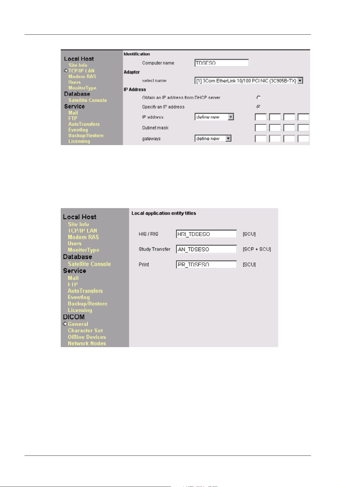
Provide the local camera service with the information in the "IP address" field (scroll down
menu for IP address).
Siemens AG COSW-000.843.01.01.02 DICOM
Medical Solutions
06.02 CS SD 24
Page 7 of 28
Page 8
8 SW Configuration for DICOM Camera
Fig. 1: Local Host TCP/IP Address
• Click on "Finish"
The Local Service Configuration Initial Setup Platform appears
Click on DICOM "General"
The local Application Entity Title Platform appears
Provide the local camera service with the information in the "Print" field (SCU) AE Title
Fig. 2: Local Application Entity Title menu
• Click on "Save"; ">"; "Finish"
• The Local Service Configuration Initial Setup Platform is displayed
• Select DICOM Print Devices
DICOM COSW-000.843.01.01.02 Siemens AG
06.02 CS SD 24
Page 8 of 28
Medical Solutions
Page 9

SW Configuration for DICOM Camera 9
NOTE
Deleting a DICOM Camera
If you need to delete a DICOM Camera, the correct procedure is to
start with menu step 3 and go back to menu step 1. Otherwise, you
will create problems with the filming tab card in the user interface,
registry settings, etc.
Siemens AG COSW-000.843.01.01.02 DICOM
Medical Solutions
06.02 CS SD 24
Page 9 of 28
Page 10

10 SW Configuration for DICOM Camera
Step 1- TCP/IP Settings for DICOM Camera 0
Fig. 3: DICOM Print Devices menu - step 1
NOTE
For additional information, please press the Help button in the
configuration mask and go to
DICOM >>Print devices>>steps 1 and 2.
Select Host 0
Click on the "Select Host" drop-down menu to see if the host name of the DICOM camera
is already listed. If so (and the related host properties are correct), you can continue with
the next menu.
If the DICOM camera is incorrect or not listed, select "define new" and define the DICOM
camera.
Host Properties 0
Enter the host name and TCP/IP address of the DICOM camera (provided by the local
camera service).
DICOM COSW-000.843.01.01.02 Siemens AG
06.02 CS SD 24
Page 10 of 28
Medical Solutions
Page 11

SW Configuration for DICOM Camera 11
Host Name 0
• Enter the host name of the DICOM camera (connected by LAN).
Find 0
• Selecting the Find button checks whether the host name is known at the WINS or Do-
main Name Server (DNS). (Note : ’Find’ works for RAS only if the RAS connection has
been established previously). If found, the IP address will be entered in the TCP/IP address field. The following response should appear:
- "Host <name> is successfully resolved." The IP address will be accepted.
TCP/IP Address 0
• If no DNS is used, you need to manually enter the IP address into these fields.
Connected by LAN / RAS 0
• Select connected by LAN (do not use ’connected by RAS’ for a DICOM camera configu-
ration)
• Click on "save"
• Host properties successfully saved
• Click on "OK"; ">"
Siemens AG COSW-000.843.01.01.02 DICOM
Medical Solutions
06.02 CS SD 24
Page 11 of 28
Page 12

12 SW Configuration for DICOM Camera
Step 2- DICOM Settings for DICOM Camera 0
Fig. 4: DICOM Print Devices menu - step 2
NOTE
For additional information, please press the Help button in the
configuration mask and go to
DICOM >>Print Devices>>steps 1 and 2.
DICOM COSW-000.843.01.01.02 Siemens AG
06.02 CS SD 24
Page 12 of 28
Medical Solutions
Page 13

SW Configuration for DICOM Camera 13
General Node Properties 0
Logical Name 0
• The logical name is used only as a link to the next menu (menu step 3). Select the logi-
cal name for the DICOM camera.
Edit Name 0
• Create or update a logical name for the DICOM camera.
Host 0
• Select the host and choose the previously defined host name in the DICOM Print De-
vice Platform for the DICOM camera.
Siemens AG COSW-000.843.01.01.02 DICOM
Medical Solutions
06.02 CS SD 24
Page 13 of 28
Page 14

14 SW Configuration for DICOM Camera
Application Entity Properties 0
AE Title 0
• The AETs already configured are shown in this pull-down menu. Select the Application
Entity Title for the DICOM camera or define a new one in the ’edit AE Title’ field.
Edit AE Title 0
• Enter the Application Entity Title of the DICOM camera (provided by the local camera
service).
Port Number 0
• The port number is the TCP/IP listener port where the DICOM process (defined by the
AET) at the DICOM camera is listening. Enter the port number of the DICOM camera
(provided by the local camera service) and press the Add button.
Add / Del 0
• If you select an AET that is already configured, the Add button will change to the Del
button, allowing you to delete this AET, if required.
Verification 0
• DICOM Verification is a DICOM service for test purposes. What is called a C-ECHO
command (mc3echo) will be transferred to the selected DICOM service, which is defined by the IP address, the port number, and the AET.
- If the verification is successful, the message "...is responding" appears.
- If the verification is not successful, the message "...is not responding" appears.
C-ECHO 0
• C-ECHO will fail for the following reasons (mc3echo):
- TCP/IP address, AET, or port number is not configured correctly.
- The DICOM process at the remote host is not running.
- Certain products check the IP address or AET of the sending system. If the AET or IP
address of the local system is not entered correctly there, DICOM verification will fail.
- The remote host does not support DICOM Verification as a Service Class Provider
(see DICOM Conformance Statement).
Supported DICOM Services 0
¹ Print is selected
DICOM COSW-000.843.01.01.02 Siemens AG
06.02 CS SD 24
Page 14 of 28
Medical Solutions
Page 15

SW Configuration for DICOM Camera 15
• Click on "save"
¹ DICOM node properties successfully saved
• Click on "OK"; ">"
Siemens AG COSW-000.843.01.01.02 DICOM
Medical Solutions
06.02 CS SD 24
Page 15 of 28
Page 16
16 SW Configuration for DICOM Camera
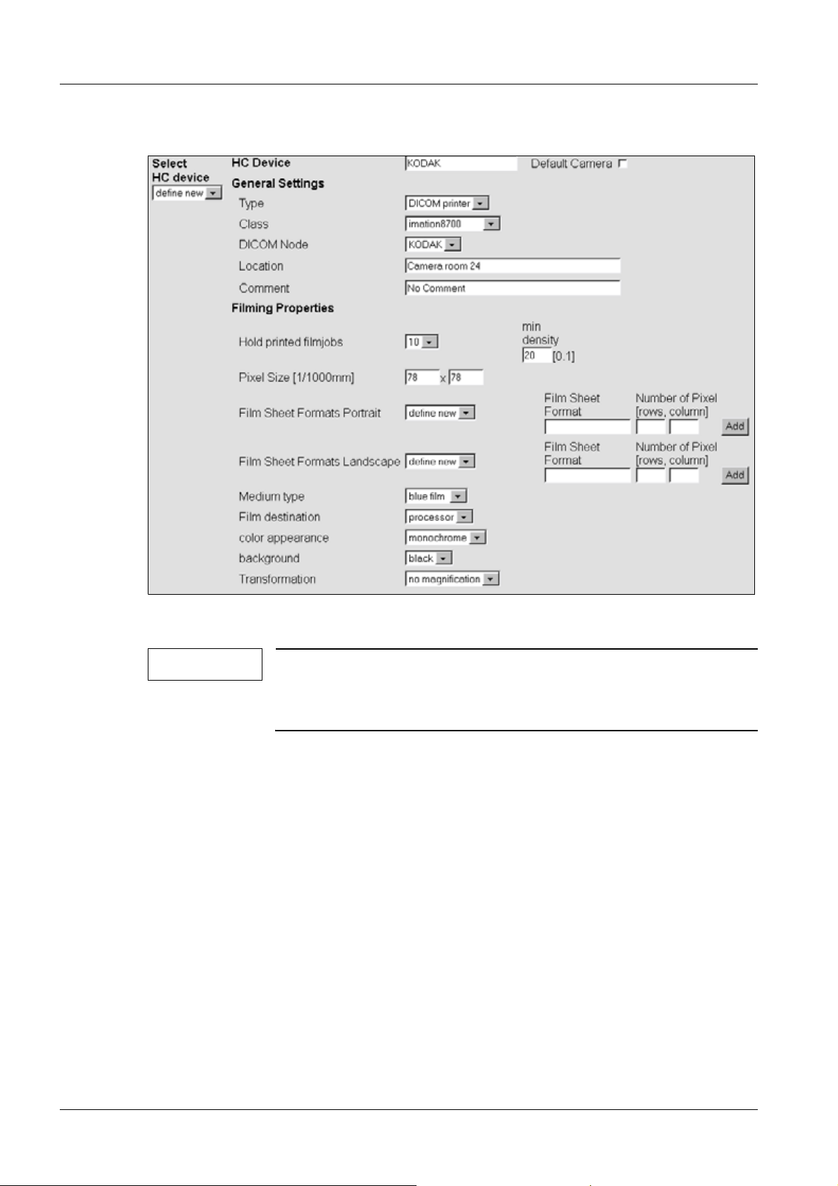
Step 3- Camera Parameter Settings 0
Fig. 5: DICOM Print Devices menu - step 3
NOTE
For additional information, please press the Help button in the
configuration mask and go to
DICOM >>Print Devices>>steps 1 and 2.
Select HC Device 0
• The DICOM cameras already configured can be selected in this pull-down menu.
HC Device 0
• Enter the name of the DICOM Camera which will be displayed in the customer user in-
terface in the Print tab card.
Default Camera 0
• When this box is selected, the DICOM camera will be set as the default camera. The
other DICOM cameras need to be selected in a pull-down menu in the Print tab card on
the customer user interface.
DICOM COSW-000.843.01.01.02 Siemens AG
06.02 CS SD 24
Page 16 of 28
Medical Solutions
Page 17

SW Configuration for DICOM Camera 17
General Settings 0
The general setting for each DICOM camera is described in "Specific Hardcopy Camera
Information" (see Overview, Additionally Required Documents)
Type 0
¹ Here you can select from the following DICOM camera types:
• DICOM printer : Select this item for all DICOM cameras and for cameras connected via
the DICOM interface box that support DICOM Basic Print.
• SPCI printer : This item is reserved. Do not use.
• SIMULATE : If the code is available, do not use.
Class 0
• A pull-down menu with DICOM cameras will be provided (e.g. imation8700). Select
your DICOM camera type. A specific file for this type will be loaded, and the ’Filming
Properties’ (see below) will be displayed. (for valid class selection, refer to [G] and/or
[S])
DICOM Node 0
• Here you will get the logical names defined in step 2 of the DICOM camera configura-
tion. Select the appropriate DICOM camera.
Location 0
• Enter the location of the DICOM camera. This information will be displayed in this con-
figuration menu only.
Comment 0
• Enter comments, such as the help desk phone number of the DICOM camera vendor.
This information will be displayed in this configuration menu only.
Siemens AG COSW-000.843.01.01.02 DICOM
Medical Solutions
06.02 CS SD 24
Page 17 of 28
Page 18

18 SW Configuration for DICOM Camera
Filming Properties 0
The displayed settings depend on the selected class (DICOM camera). See also Overview, Additionally Required Documents
Hold Printed Film Jobs 0
• The most recent film jobs will remain in the print queue, even after a film has been suc-
cessfully printed. The number of films in the queue is defined here. default setting = 10;
max = 10
Min Density [1/100 O.D.] 0
• Set the minimum density value for the film used, default setting = 20; this value can be
changed in increments/decrements of 1 (the maximum density value is modality-dependent and is set in the ’LUT files’ menu).
Pixel Size [1/1000 mm] 0
• This is the pixel dot size specified for this DICOM camera. Do not change, unless other-
wise noted.
Portrait / Landscape Film Sheet Formats 0
• All formats (media sheet sizes and orientation) specified for this DICOM camera are
provided in these fields. Select film sizes and delete only those not available on site. Do
not change (modify and/or add film sizes), unless otherwise noted.
Number of Pixel [rows, columns] 0
• The number of pixels (rows and columns) specified for this DICOM camera are provid-
ed in this field. Do not change (modify Number of Pixels), unless otherwise noted.
Medium Type 0
• The possible medium types are provided in this field, default setting = blue film
Film Destination 0
• The possible film destination ’magazine’ or ’processor’ is provided in this field. Select
the film destination as specified by the local camera service, default setting = processor
DICOM COSW-000.843.01.01.02 Siemens AG
06.02 CS SD 24
Page 18 of 28
Medical Solutions
Page 19

SW Configuration for DICOM Camera 19
Color Appearance 0
• The possible color appearance, ’monochrome’ or ’color’ is provided in this field. The
’color’ setting is a special feature and must be supported by the modality and DICOM
camera, default setting = monochrome. Do not change, unless otherwise noted.
Background 0
• The background of the film can be set to ’black’ or ’white’, default setting = black
Transformation 0
Normally no transformation; in special cases, an additional transformation is required in
the DICOM camera. The following values are possible:
• replicate: the interpolated value is identical to the last pixel value
• bilinear: the interpolated value is between (linear) the last pixel value and the next pixel
value
• cubic: the interpolated value is in between (curve) the last pixel value and the next pixel
value
• no magnification: leaves the image as is, default setting = no magnification. Do not
change, unless otherwise noted
• Click on "save"
• Caution: Please wait for the message "device properties successfully saved".
• Click on "OK"; "Finish"
NOTICE
Deleting Print Devices
If a DICOM camera is to be deleted from the configuration settings,
start the deletion with menu step 3 of the print device setup and go
back to menu step 1. Otherwise, the error massage "Option value
warning: Invalid node could not be found" will be displayed.
¹ To enter a new DICOM camera, always start with menu
step 1 of the setup.
Siemens AG COSW-000.843.01.01.02 DICOM
Medical Solutions
06.02 CS SD 24
Page 19 of 28
Page 20

20 SW Configuration for DICOM Camera
HC Overview 0
Overview of the HC Settings 0
The HC Overview (Hardcopy Overview) menu displays the settings made previously.
There is no need for the field service engineer to use this menu, since the settings and
tests can also be performed via the ’print device’ menu.
Fig. 6: DICOM HC Overview menu
These menu items were described previously in step 3, DICOM Print Device menu.
NOTE
DICOM COSW-000.843.01.01.02 Siemens AG
For additional information, please press the Help button in the
configuration mask and go to
DICOM >>print devices>>steps 1 and 2.
06.02 CS SD 24
Page 20 of 28
Medical Solutions
Page 21
SW Configuration for DICOM Camera 21
LUT Files 0
This menu allows you to import, remove, and select LUT files (Look Up Table) for DICOM
Basic Print. No tool is available for modifying a lookup table (LUT editor).
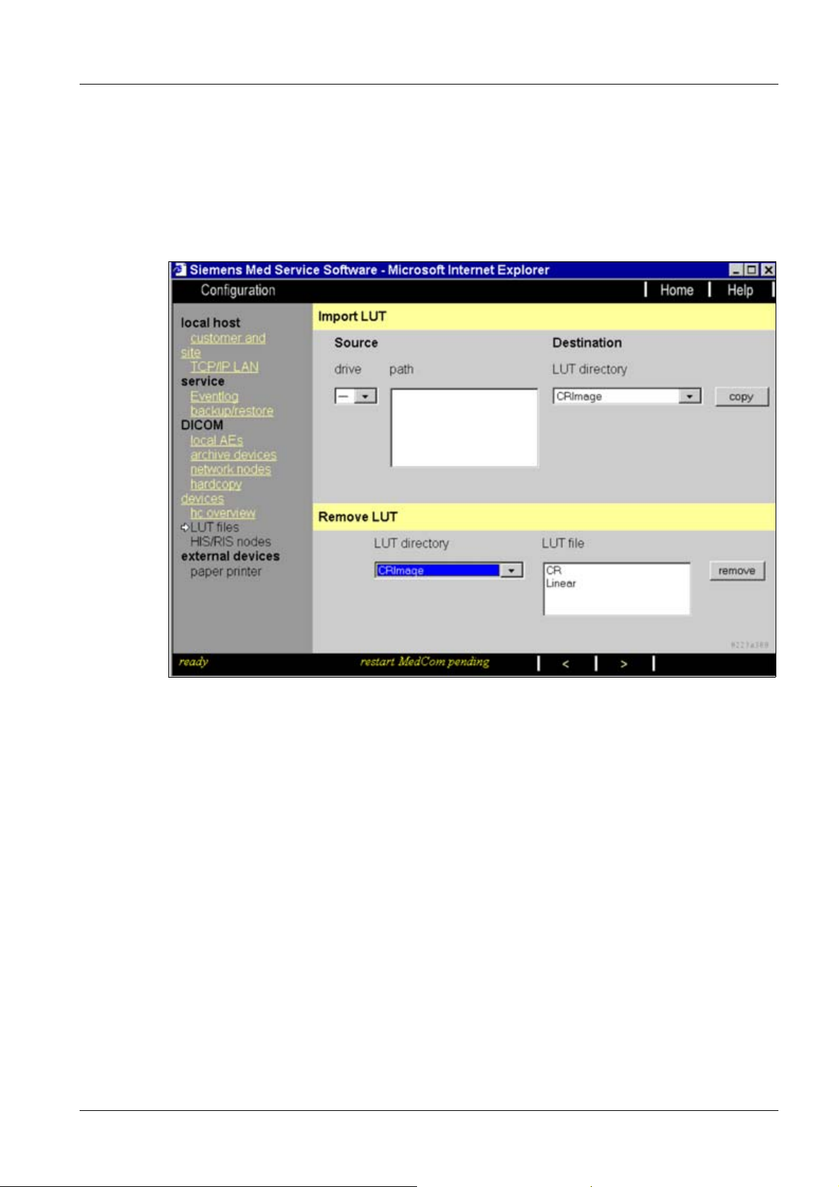
Import of Additional LUT Files 0
Fig. 7: DICOM LUT Files menu (import / remove)
Import LUT 0
If new LUT files are available on a removable medium (e.g., floppy or CD) for one or more
modalities, these files can be selected on the source drive and copied to the corresponding LUT directories on the local system. Unnecessary LUT files can be removed from LUT
directories on the local system
Source 0
• Select the drive and path where the appropriate LUT file is located.
Destination 0
• Select the destination LUT directory according to image type. Pressing the ’copy’ but-
ton transfers the selected LUT file.
Siemens AG COSW-000.843.01.01.02 DICOM
Medical Solutions
06.02 CS SD 24
Page 21 of 28
Page 22

22 SW Configuration for DICOM Camera
Remove LUT 0
Unneeded LUT files can be removed from LUT directories on the local host by selecting
the appropriate LUT file and pressing the ’remove’ button.
• Click on ">"
General LUT Setting Information 0
NOTE
The image data from the modality to the DICOM camera are transformed / corrected by
the LUT‘s, at least once in the modality and once in the DICOM camera; the LUT must be
set on both sides.
The LUT setting will be performed
Each modality requires its own LUT setting. Depending on the modality, please refer to "General Hardcopy Camera Information"
• for the modality: in this menu with different options (see below)
• for the DICOM camera: with a different mechanism (refer to [S]), i.e.
- by LUT number or LUT name in the keypad or menu mode
- by a modality-specific file or default configuration file in menu mode
The LUT selection depends on
• the modality: for each image per film sheet on the image type
• the DICOM camera: for each film sheet on a different mechanism, i.e.
- modality independent (fixed LUT)
- depending on modality by the calling AET
- depending on the required port number
Menu Options 0
There are 3 possible settings for image presentation
1. Usage of Presentation LUT disabled: The image data will be corrected by a Correction
LUT (also called modality-specified LUT or GG LUT). In this case, each DICOM camera has to be set to LINEAR LUT.
2. Use of Presentation LUT enabled AND DICOM p-Value Interface supported by all connected cameras: The image data will be corrected by a Presentation LUT. In this case,
each DICOM camera has to be set to GSDF (Gray Scale Standard Display Function).
Note: it is not possible to mix cameras that support GSDF with those that do not!
3. Use of Presentation LUT enabled AND DICOM p-Value Interface not supported by all
connected cameras: The image data will be corrected by a Presentation LUT AND a
Correction LUT. In this case, each DICOM camera has to be set to LINEAR LUT (the
GSDF will be performed in the modality instead of in the DICOM camera).
DICOM COSW-000.843.01.01.02 Siemens AG
06.02 CS SD 24
Page 22 of 28
Medical Solutions
Page 23

SW Configuration for DICOM Camera 23
NOTE
The options "Use of Presentation LUT enabled with DICOM p-value
interface supported/not supported by all connected cameras" is a
work in progress
LUT Settings 0
The following are the default settings for "Use of Presentation LUT disabled." Please do
not change, unless otherwise noted.
Siemens AG COSW-000.843.01.01.02 DICOM
Medical Solutions
06.02 CS SD 24
Page 23 of 28
Page 24

24 SW Configuration for DICOM Camera
Fig. 8: Use of Presentation LUT disabled
DICOM COSW-000.843.01.01.02 Siemens AG
06.02 CS SD 24
Page 24 of 28
Medical Solutions
Page 25

SW Configuration for DICOM Camera 25
Correction LUT / Presentation LUT 0
• For an explanation, see Menu Options (above). Special settings depend on the modali-
ty (see Overview, Additionally Required Documents) (Note: ’Presentation LUT’ and
’Correction LUT’ are logical names and do not correspond to each other with the different options; i.e. both Presentation LUTs in the 2nd and 3rd option case can have the
same name but different contents).
Max Density 0
• This value is required for each LUT and is imported together with the LUT (do not
change this default value, unless otherwise noted). This value will be used together with
’Overall maximum density’ to scale the image presentation for each image per film
sheet (Hint : the Min Density value will be set once in the ’Print device menu’).
Overall Maximum Density 0
• This value will be used to set the maximum required density on the film. Default setting
= 3.00. (The overall maximum density value has to be equal to or higher than the "Max
Density Entries" for the different image types).
Interpolation for Printing 0
• The complete film sheet is calculated in the modality and then be sent to the DICOM
camera (page mode). To fit the images into this virtual film sheet, pixel interpolation is
required. Do not change, unless otherwise noted. The following values are possible:
replicate: the interpolated value is identical to the last pixel value bilinear: the interpolated value is between (linear) the last pixel value and the next pixel value; cubic: the interpolated value is between (curve) the last pixel value and the next pixel value
Mode 0
• The smoothing type factor can be selected for the cubic interpolation algorithm only
(smoothing factors are 0, 2, 3, 4). Do not change, unless otherwise noted.
• Click on "save" after making the changes
• Click on "finish"
• Click on "Home"; the system restarts automatically
NOTE
If the message "restart Syngo pending" appears in the bottom status line; an application
restart is automatic after the "HOME" button is pressed.
This may take some time.
If the message "shutdown Syngo pending" appears in the bottom status line; a system
restart is automatic after the "HOME" button is pressed.
Confirm the warnings with "OK."
Siemens AG COSW-000.843.01.01.02 DICOM
Medical Solutions
06.02 CS SD 24
Page 25 of 28
Page 26
26 SW Configuration for DICOM Camera
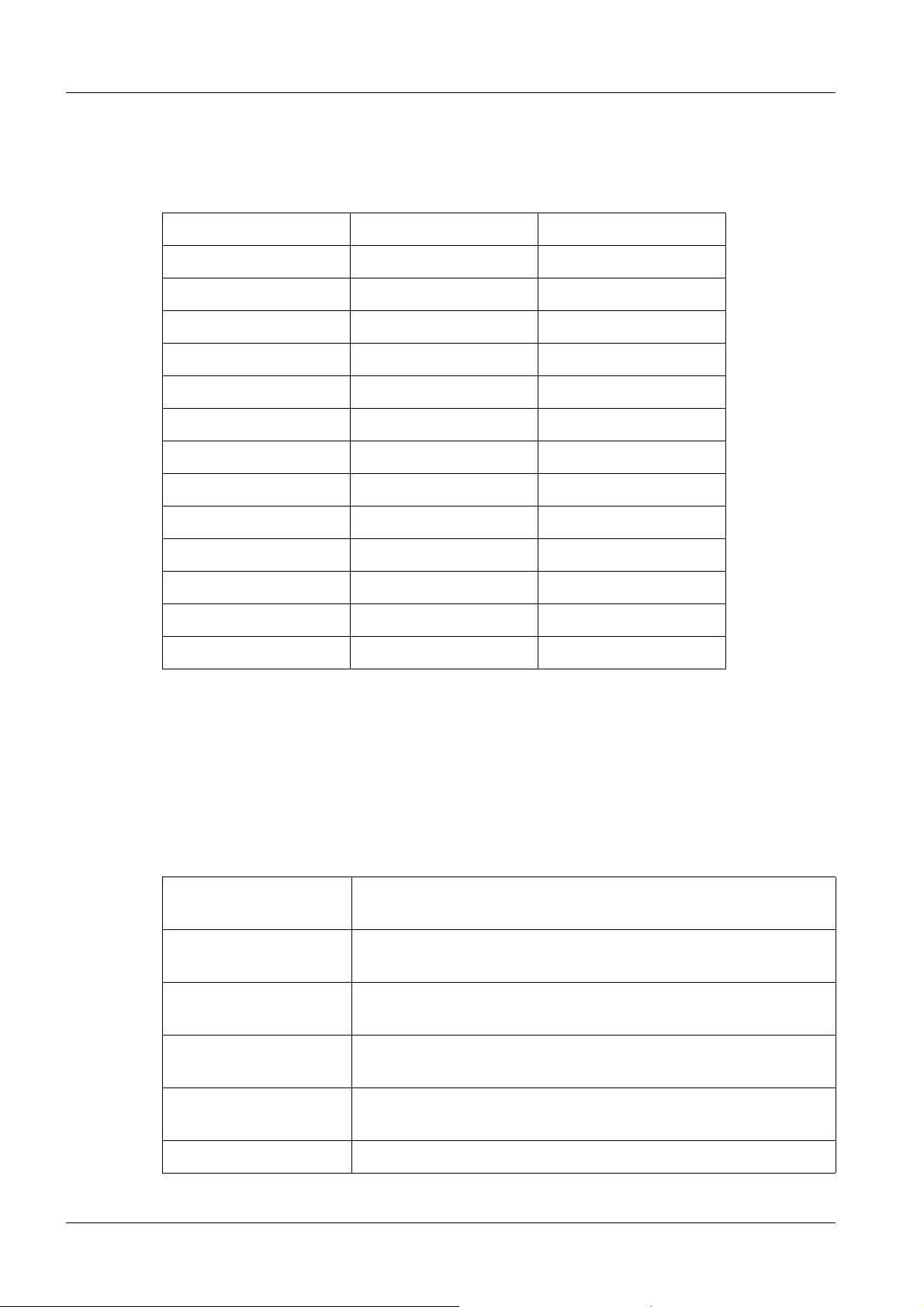
Standard LUT Files for Siemens Modalities 0
Based on the VB10x Syngo software, only the standard LUTs are implemented. The following LUTs are the default standard LUTs.
Image type Correction LUT Max Density
CRImage cr 3.00
CTImage CTLUT (*1) 2.80
DXImage Linear 3.00
USMFImage USMF 2.40
MRImage MR1 (*2) 3.00
USImage us 2.40
SCImage sc 2.80
SAOverlay SAOverlay 3.00
SACurve SACurve 3.00
XAImage xa 3.00
XRImage xrf 3.00
XABiPlaneImage xabipl 3.00
NMImage NM 3.00
DICOM default setting, Siemens LUT files
*1 and *2, see Non-Standard LUT files for Siemens Modalities
Non-Standard LUT Files for Siemens Modalities 0
For CT systems, additional LUTs are available from the BU.
"Image type" CTImage "Correction LUT" CT LUT (*1)
CTLUT: Standard LUT; default LUT for all wet DICOM cameras; adapts
Dmin of 0.2
CT2 vs. CTLUT: Dark area = less contrast; darker; softer; white area = more
contrast
CT3 vs. CT2: Dark area = less contrast; darker; softer; white area = more
contrast
CT4 vs. CTLUT: Dark area = more contrast; darker; sharper; white area: no
changes
CT5 vs. CTLUT: Brighter; no change of contrast for large window width; more
contrast for head images (small window width)
CT6 vs. CTLUT: Brighter than CT5; white area = less contrast
DICOM COSW-000.843.01.01.02 Siemens AG
06.02 CS SD 24
Page 26 of 28
Medical Solutions
Page 27

SW Configuration for DICOM Camera 27
cthead1: LUT for head images, images smoother, impression of head
images of Somatom Emotion Duo similar to Somatom Plus4
cthead2 vs. cthead1: Images smoother; but sharper impression than Somatom
Plus4 images
CT015: Adapts Dmin. of 0.15 (for DICOM cameras not supported by
Dmin. command)
CT017: Adapts Dmin. of 0.17 (for DICOM cameras not supported by
Dmin. command)
CTLUTdry; Default LUT for dry DICOM cameras; adapts Dmin of 0.22
CTLung LUT for lung images
For MR systems, some additional LUTs are available from the BU.
"Image type" MRImage "Correction LUT" MR1LUT (*2)
MR1 LUT (Standard LUT) and max. density 2.80 - 3.00 (recommended 3.00)
MR2 LUT (LUT for "softer contrast) and max. density 2.80 - 3.00 (recommended 3.00)
Siemens AG COSW-000.843.01.01.02 DICOM
Medical Solutions
06.02 CS SD 24
Page 27 of 28
Page 28

28 SW Configuration for DICOM Camera
DICOM COSW-000.843.01.01.02 Siemens AG
06.02 CS SD 24
Page 28 of 28
Medical Solutions
 Loading...