

Page 1

SIMOTION
Preface
Description
Commissioning (hardware)
1
2
D410
Commissioning Manual
Configuring SIMOTION
D410
Commissioning (software)
Maintenance and service
Diagnostics data
Standards and approvals
ESD guidelines
Appendix
3
4
5
6
A
B
C
Valid for SIMOTION D410 DP and D410 PN
08/2008 Edition
Page 2

Safety Guidelines
This manual contains notices you have to observe in order to ensure your personal safety, as well as to prevent
damage to property. The notices referring to your personal safety are highlighted in the manual by a safety alert
symbol, notices referring only to property damage have no safety alert symbol. These notices shown below are
graded according to the degree of danger.
DANGER
indicates that death or severe personal injury will result if proper precautions are not taken.
WARNING
indicates that death or severe personal injury may result if proper precautions are not taken.
CAUTION
with a safety alert symbol, indicates that minor personal injury can result if proper precautions are not taken.
CAUTION
without a safety alert symbol, indicates that property damage can result if proper precautions are not taken.
NOTICE
indicates that an unintended result or situation can occur if the corresponding information is not taken into
account.
If more than one degree of danger is present, the warning notice representing the highest degree of danger will
be used. A notice warning of injury to persons with a safety alert symbol may also include a warning relating to
property damage.
Qualified Personnel
The device/system may only be set up and used in conjunction with this documentation. Commissioning and
operation of a device/system may only be performed by qualified personnel. Within the context of the safety notes
in this documentation qualified persons are defined as persons who are authorized to commission, ground and
label devices, systems and circuits in accordance with established safety practices and standards.
Prescribed Usage
Note the following:
WARNING
This device may only be used for the applications described in the catalog or the technical description and only
in connection with devices or components from other manufacturers which have been approved or
recommended by Siemens. Correct, reliable operation of the product requires proper transport, storage,
positioning and assembly as well as careful operation and maintenance.
Trademarks
All names identified by ® are registered trademarks of the Siemens AG. The remaining trademarks in this
publication may be trademarks whose use by third parties for their own purposes could violate the rights of the
owner.
Disclaimer of Liability
We have reviewed the contents of this publication to ensure consistency with the hardware and software
described. Since variance cannot be precluded entirely, we cannot guarantee full consistency. However, the
information in this publication is reviewed regularly and any necessary corrections are included in subsequent
editions.
Siemens AG
Industry Sector
Postfach 48 48
90327 NÜRNBERG
GERMANY
Copyright © Siemens AG 2008.
Technical data subject to change
Page 3

Preface
Contents of the commissioning manual
This manual is part of the SIMOTION D4xx documentation package, Edition 08/2008.
This manual describes commissioning of the SIMOTION devices D410 DP and D410 PN.
Information blocks in this manual
The following information blocks describe the purpose and use of the commissioning
manual.
● Description
This section provides information pertaining to the SIMOTION system and its integration
into the information landscape.
● Commissioning (hardware)
This section describes how to start up the device and what you must take into account.
● Configuring SIMOTION D410
This section describes how to integrate SIMOTION D410 in a project and how to
configure the interfaces.
● Commissioning (software)
This section describes how to configure a plant and how to test the drives and axes you
configured.
● Maintenance and service
This section describes how to replace a module, how to run updates, and how to modify
settings.
● Diagnostics data
This section provides information about diagnostic possibilities and LED states.
● Appendices with factual information for reference (for example, Standards and Approvals,
and ESD)
● Index for locating information.
SIMOTION Documentation
An overview of the SIMOTION documentation can be found in a separate list of references.
This documentation is included as electronic documentation with the supplied SIMOTION
SCOUT.
D410
Commissioning Manual, 08/2008 Edition
3
Page 4

Preface
The SIMOTION documentation consists of 9 documentation packages containing
approximately 80 SIMOTION documents and documents on related systems (e.g.
SINAMICS).
The following documentation packages are available for SIMOTION V4.1 SP2:
● SIMOTION Engineering System
● SIMOTION System and Function Descriptions
● SIMOTION Diagnostics
● SIMOTION Programming
● SIMOTION Programming - References
● SIMOTION C
● SIMOTION P350
● SIMOTION D4xx
● SIMOTION Supplementary Documentation
Hotline and Internet addresses
Technical support
If you have any technical questions, please contact our hotline:
Europe / Africa
Phone +49 180 5050 222 (subject to charge)
Fax +49 180 5050 223
Internet http://www.siemens.com/automation/support-request
Americas
Phone +1 423 262 2522
Fax +1 423 262 2200
E-mail mailto:techsupport.sea@siemens.com
Asia / Pacific
Phone +86 1064 719 990
Fax +86 1064 747 474
E-mail mailto:adsupport.asia@siemens.com
D410
4 Commissioning Manual, 08/2008 Edition
Page 5

Preface
Note
Country-specific telephone numbers for technical support are provided under the following
Internet address:
http://www.siemens.com/automation/service&support
Calls are subject to charge, e.g. 0.14 €/min. on the German landline network. Tariffs of other
phone companies may differ.
Questions about this documentation
If you have any questions (suggestions, corrections) regarding this documentation, please
fax or e-mail us at:
Fax +49 9131- 98 63315
E-mail mailto:docu.motioncontrol@siemens.com
Siemens Internet address
The latest information about SIMOTION products, product support, and FAQs can be found
on the Internet at:
● General information:
Additional support
– http://www.siemens.de/simotion (German)
– http://www.siemens.com/simotion (international)
● Product support:
– http://support.automation.siemens.com/WW/view/en/10805436
We also offer introductory courses to help you familiarize yourself with SIMOTION.
Please contact your regional training center or our main training center at D-90027
Nuremberg, phone +49 (911) 895 3202.
Information about training courses on offer can be found at:
www.sitrain.com
D410
Commissioning Manual, 08/2008 Edition
5
Page 6

Preface
Disposal and recycling
SIMOTION D410 is an environmentally friendly product! It includes the following features:
● In spite of its excellent resistance to fire, the flame-resistant agent in the plastic used for
the housing does not contain halogens.
● Identification of plastic materials in accordance with DIN 54840
● Less material used because the unit is smaller and with fewer components thanks to
integration in ASICs
SIMOTION D410 can be recycled because it is made with low-polluting materials.
For state-of-the art environmentally friendly recycling and disposal of your old modules,
contact your Siemens representative. To locate your representative, visit us online at:
http://www.ad.siemens.com/partner
Further information / FAQs
You can find further information on this manual under the following FAQs:
http://support.automation.siemens.com/WW/view/de/27585482
The following resources are also available:
● SIMOTION - Utilities & Applications CD: This CD is supplied together with the SIMOTION
SCOUT and, along with FAQs, also contains free utilities (e.g. calculation tools,
optimization tools, etc.) and application examples (ready-to-apply solutions such as
winder, cross cutter or handling).
● The latest FAQs for SIMOTION can be found at:
http://support.automation.siemens.com/WW/view/de/10805436
● SIMOTION SCOUT online help
● Additional documentation: see SIMOTION references
D410
6 Commissioning Manual, 08/2008 Edition
Page 7

Table of contents
Preface ...................................................................................................................................................... 3
1 Description...............................................................................................................................................
1.1 System overview ..........................................................................................................................
1.2 System components ....................................................................................................................
1.3 SIMOTION D410 DP display .......................................................................................................
1.4 SIMOTION D410 PN display .......................................................................................................
1.5 The CompactFlash card...............................................................................................................
1.6 Licensing ......................................................................................................................................
1.7 Safety information ........................................................................................................................
2 Commissioning (hardware)......................................................................................................................
2.1 Prerequisites for commissioning ..................................................................................................
2.2 Inserting the Compact Flash card ................................................................................................
2.3 Switching on the power supply ....................................................................................................
2.4 RESET button ..............................................................................................................................
2.5 User memory concept..................................................................................................................
2.5.1 SIMOTION D410 memory model.................................................................................................
2.5.2 Properties of the user memories..................................................................................................
2.5.3 Operator actions and their impact on user memory.....................................................................
3 Configuring SIMOTION D410 ..................................................................................................................
11
11
14
19
23
27
28
29
31
31
32
33
34
35
35
36
38
43
3.1 Software requirements.................................................................................................................
3.2 Inserting SIMOTION D410 into a project .....................................................................................
3.3 Configuring the PROFIBUS DP interface (only D410 DP) ..........................................................
3.3.1 General information about PROFIBUS DP communication ........................................................
3.3.2 Assignment of the PROFIBUS addresses in HW Config.............................................................
3.3.3 Operating SIMOTION D410 on PROFIBUS DP. .........................................................................
3.3.4 Creating a new PROFIBUS DP subnet .......................................................................................
3.3.5 Setting the DP cycle and system cycle clocks.............................................................................
3.3.6 Rules for SIMOTION D410 DP ....................................................................................................
3.4 Configuring PROFINET (only for D410 PN) ................................................................................
3.4.1 General information about PROFINET communication...............................................................
3.4.2 Operating SIMOTION D410 PN on PROFINET ..........................................................................
3.4.3 Setting the send cycles and system clocks .................................................................................
3.4.4 Rules for SIMOTION D410 PN ....................................................................................................
4 Commissioning (software) .......................................................................................................................
4.1 Overview of commissioning .........................................................................................................
4.2 Configuring the system in offline mode........................................................................................
D410
Commissioning Manual, 08/2008 Edition
43
43
46
46
47
48
48
49
50
52
52
53
56
58
61
61
62
7
Page 8

Table of contents
4.2.1 Overview ..................................................................................................................................... 62
4.2.2 Accessing the drive wizard..........................................................................................................
4.2.3 Configuring the components .......................................................................................................
4.2.4 Aligning HW Config.....................................................................................................................
4.2.5 Downloading the project to SIMOTION D410.............................................................................
63
64
70
71
4.3 Configuring the system in online mode.......................................................................................
4.3.1 Overview .....................................................................................................................................
4.3.2 Establishing the online connection..............................................................................................
4.3.3 Starting automatic configuration .................................................................................................
4.3.4 Editing SINAMICS components ..................................................................................................
4.3.5 Aligning HW Config.....................................................................................................................
4.3.6 Download the project to SIMOTION D410..................................................................................
4.4 Creating an axis ..........................................................................................................................
4.5 Integrating additional encoders (optional)...................................................................................
4.5.1 General information.....................................................................................................................
4.5.2 Configure the encoder interface on the drive side ......................................................................
4.5.3 Configuring a second encoder for a TO axis in SIMOTION........................................................
4.5.4 Configuring external encoders in SIMOTION .............................................................................
4.6 Using drive-related I/Os by SIMOTION.......................................................................................
4.6.1 Onboard I/Os and terminal modules configuration overview......................................................
4.6.2 Use of message frame 39x .........................................................................................................
4.6.3 Free message frame configuring with P915/P916 (only TM15/TM17 High Feature) .................
4.6.4 Configuring free message frames by means of BICO ................................................................
4.6.5 Expanding a message frame ......................................................................................................
4.6.6 Using high-speed outputs for output cams on D410.................................................................
4.6.7 Using probe inputs on D410......................................................................................................
4.6.8 Outputs of cam outputs and probe inputs on TM15/TM17 High Feature .................................
4.7 Creating and programming TM41 .............................................................................................
4.7.1 Overview ...................................................................................................................................
4.7.2 Configuring TM41 at SINAMICS Integrated..............................................................................
73
73
74
75
77
78
78
79
81
81
82
83
84
85
85
87
91
92
97
100
101
105
106
106
106
4.8 Creating a DMC20 ....................................................................................................................
4.8.1 DMC20 hub properties..............................................................................................................
4.8.2 Creating a DRIVE-CLiQ hub .....................................................................................................
4.9 Testing the configured drive using the drive control panel .......................................................
4.10 Testing the configured axis using the axis control panel ..........................................................
4.11 Downloading and saving user data...........................................................................................
4.12 Deleting data .............................................................................................................................
4.12.1 Overview of data deletion..........................................................................................................
4.12.2 Resetting the memory of SIMOTION D410 ..............................................................................
4.12.3 Deleting user data from the CompactFlash Card .....................................................................
4.12.4 Restoring the default settings of SINAMICS Integrated............................................................
4.12.5 Restoring the default settings of SIMOTION D410...................................................................
4.13 System shutdown......................................................................................................................
5 Maintenance and service.......................................................................................................................
5.1 Replacing modules....................................................................................................................
5.1.1 Removing and replacing the SIMOTION D410.........................................................................
5.1.2 Replacing DRIVE-CLiQ components ........................................................................................
5.2 Replacing the fan ......................................................................................................................
D410
107
107
108
109
111
113
114
114
115
117
118
118
119
121
121
121
124
125
8 Commissioning Manual, 08/2008 Edition
Page 9

Table of contents
5.3 Performing a software and firmware update..............................................................................126
5.4 SIMOTION CompactFlash Card ................................................................................................
5.4.1 Replacing the CompactFlash Card............................................................................................
5.4.2 Writing and deleting data on CompactFlash Cards ...................................................................
5.4.3 Formatting the CompactFlash Card...........................................................................................
5.4.4 Bootloader on the CompactFlash card ......................................................................................
6 Diagnostics data ....................................................................................................................................
6.1 Diagnostics by means of LED displays......................................................................................
6.2 Extended diagnostic capabilities................................................................................................
A Standards and approvals.......................................................................................................................
A.1 General rules..............................................................................................................................
A.2 Safety of electronic controllers...................................................................................................
A.3 Electromagnetic Compatibility....................................................................................................
B ESD guidelines ......................................................................................................................................
B.1 ESD definition ............................................................................................................................
B.2 Electrostatic charging of individuals...........................................................................................
B.3 Basic measures for protection against discharge of static electricity ........................................
C Appendix................................................................................................................................................
C.1 List of abbreviations...................................................................................................................
Index......................................................................................................................................................
131
131
131
132
133
135
135
138
139
139
140
142
143
143
143
144
145
145
147
D410
Commissioning Manual, 08/2008 Edition
9
Page 10

Page 11

Description
1.1 System overview
Overview
In SIMOTION D, the SIMOTION functionality is integrated directly in the closed-loop control
module of the SINAMICS S120 drive system.
SIMOTION D410 is a module drive system for single axes, which solves demanding drive
tasks for a very wide range of industrial applications. SIMOTION D410 supplements D425,
D435 and D445, the three power levels for multi-axis connections.
SIMOTION D is an integral part of the Totally Integrated Automation (TIA) concept. TIA
features standardized data management, configuration and communication over all products
and systems. Thus, an extensive toolbox of automation modules is also available for
SIMOTION D410.
Application
Combining a power module with SIMOTION D410 forms a compact single drive for machine
and plant engineering.
1
Applications include:
● Machine concepts with central drive (e.g., pressing, printing and packaging machines, . .
.)
● Modular machine concepts where the machine modules broken down to single axes
● Single drives with high accuracy, stability and concentricity requirements (compared with
standard drives) in machine and industrial plant engineering
● Single drives for transport tasks (conveying, raising, lowering)
● Single drives with integrated PLC functionality and expanded motion control functionality
such as output cam or cams
● Drives without power recovery (wire drawing, extruding)
● Drive connections with high availability requirements (incoming supply failure may not
cause all axes to fail)
Product variants
SIMOTION D410 comes in two variants:
● SIMOTION D410 DP with PROFIBUS DP interface.
● SIMOTION D410 PN with PROFINET interface.
D410
Commissioning Manual, 08/2008 Edition
11
Page 12

Description
1.1 System overview
System integration
SIMOTION provides an optimized system platform for automation and drive solutions where
the main focus is on motion control applications and technology tasks.
The SIMOTION system is made up of three components:
● SIMOTION SCOUT Engineering System
● Runtime Software
● Hardware platforms
The innovative SIMOTION concept involves integrating pure automation and motion
functions, which have been traditionally isolated in the past.
3/&IXQFWLRQDOLW\
,(&
7KHV\VWHPDSSURDFKRI
0RWLRQ&RQWURO
HJSRVLWLRQLQJ
V\QFKURQRXVRSHUDWLRQHWF
7HFKQRORJ\
IXQFWLRQV
HJK\GUDXOLFVWHPSHUDWXUH
FRQWUROHWF
Figure 1-1 System solution
6,027,21
7KHFRPELQLQJRIPRWLRQ
FRQWURO3/&DQG
WHFKQRORJ\IXQFWLRQV
SIMOTION can be used with all machines with motion control tasks. The focus is on a
simple and flexible solution to a wide variety of motion control tasks. In order to achieve this
in the best way possible, a new system approach has been introduced:
the fusion of motion control with two other control functions, which are found in most
machines: PLC and technology functions.
This approach enables motion control of axes and machines with only one system. The
same applies to technology functions, such as pressure control of a hydraulic axis. A
seamless switch can be made from position-controlled positioning mode to pressure control.
D410
12 Commissioning Manual, 08/2008 Edition
Page 13

Description
1.1 System overview
Combining the three control functions of motion control, PLC and technology functions has
the following benefits:
● Lower engineering expenditure and higher machine performance.
● Interfaces between individual components requiring rapid response are no longer
needed.
● Simple, standardized and transparent programming and diagnostics for the complete
machine.
D410
Commissioning Manual, 08/2008 Edition
13
Page 14

Description
1.2 System components
1.2 System components
Overview
SIMOTION D410 communicates with the components of the automation landscape via the
following interfaces:
● PROFIBUS DP (SIMOTION D410 DP only)
● PROFINET (SIMOTION D410 PN only)
● DRIVE-CLiQ (DRIVE Component Link with IQ)
● Power Module Interface (PM-IF)
● SIMOTION D features a SINAMICS Integrated drive element. Communication with the
SINAMICS Integrated (node 3) is via PROFIBUS mechanisms (DP integrated).
The most important system components and their functions are listed in the following table.
Table 1-1 System components
Components Function
SIMOTION D410 ... is the central motion control module.
The module contains the programmable SIMOTION Runtime in
SIMOTION D410 and the SINAMICS S120 drive software.
You can use the integrated rapid digital I/Os as:
• Homing inputs
• Inputs for measuring inputs
• User-addressable process inputs/outputs
• Outputs for fast output cams
The measuring sockets can output any analog signals.
The DRIVE-CLiQ interface permits a fast connection to the SINAMICS drive
components.
System software The system software is delivered separately on a CompactFlash card (not
included in the scope of delivery).
Note: An additional license is not required for the real axis technology.
Power supply (PS) ... provides the electronic power supply for SIMOTION D410 (e.g., SITOP
power supply).
Note: If the SIMOTION D410 is snapped-on to a PM340 power module, the
power module may be used as the sole supply for the SIMOTION D410 in
certain cases (e.g., when digital outputs are not used, etc. . .). See the section
entitled in the SIMOTION D410 Manual.
D410
14 Commissioning Manual, 08/2008 Edition
Page 15

Description
1.2 System components
PROFIBUS DP
SIMOTION D410 DP can communicate via PROFIBUS DP interface to the following
components:
Table 1-2 Components on PROFIBUS DP
Components Function
PG/PC programming device ... configures, sets parameters, programs and tests using the
SIMOTION SCOUT Engineering System (ES).
SIMATIC HMI device ... is used for operator control and monitoring functions. It is not
absolutely required to run SIMOTION D410.
Drive units with
PROFIBUS DP interface
(e.g., SINAMICS,
SIMODRIVE 611 universal)
SIMATIC ET 200M Modular I/O system for control cabinet installation and high channel
SIMATIC ET 200S Finely scalable I/O system for control cabinet installation and
SIMATIC ET 200pro Modular I/O system with IP65/IP67 rating for machine-related
SIMATIC ET 200eco I/O system with IP65/IP67 rating for machine-related applications
Gateways
Teleservice adapter Remote diagnosis
Other controls (e.g.,
SIMOTION or SIMATIC)
... convert speed setpoints into signals for controlling the motor and
supply the power required to operate the motors.
Can also be operated as an isochronous, equidistant Slave on the
PROFIBUS DP.
densities.
particularly time-critical applications; including motor starters, safety
technology and individual grouping of load groups.
applications with no control cabinet; with new features such as more
compact designs, integrated PROFIsafe safety technology,
PROFINET connection and live module replacement.
with no control cabinet, with a flexible and fast connection system in
ECOFAST or M12.
• DP/AS Interface Link 20E and DP/AS Interface Link Advanced for
the PROFIBUS DP gateway to AS Interface
• DP/DP coupler to connect two PROFIBUS DP networks
Note
Note that only one real axis can be used on a SIMOTION D410.
D410
Commissioning Manual, 08/2008 Edition
15
Page 16

Description
1.2 System components
Note
Please note that not all modules for the I/O systems listed above are enabled for SIMOTION.
Moreover, system-related functional differences can come into play when these I/O or I/O
systems are used on SIMOTION vs. on SIMATIC. For example, special process-control
functions (e.g., HART modules, etc.) are not supported by SIMOTION for the ET 200M
distributed I/O system.
A list of all I/O modules that can currently be used with SIMOTION is available under the
following link:
http://support.automation.siemens.com/WW/view/de/11886029
In addition to the I/O modules enabled for SIMOTION, all certified standard slaves can, in
principle, be connected to SIMOTION if they support the following:
● Cyclic data traffic (DP-V0) and, possibly
● Acyclic data traffic (DP-V1) or
● Isochronous data traffic (DP-V2)
These modules are integrated via the GSD file from the device manufacturer.
Note
Please note that in individual cases further boundary conditions must be fulfilled in order to
integrate a standard slave into SIMOTION. For example, "driver modules" in the form of
function blocks are required for some modules, which enable integration or make it
especially easy.
For modules enabled for SIMOTION (e.g., S7-300 module FM 350-1, etc.), these driver
modules are part of the SIMOTION SCOUT Engineering System command library.
D410
16 Commissioning Manual, 08/2008 Edition
Page 17

Description
1.2 System components
PROFINET
SIMOTION D410 PN can communicate via PROFINET interface to the following
components:
Table 1-3 Components on PROFINET
Components Function
The master computer (at
company and production
management level)
PG/PC programming device ... communicates with the SIMOTION SCOUT Engineering
SIMATIC HMI device ... is used for operator control and monitoring functions. It is not
Drive units with PROFINET
interface (e.g., SINAMICS S120
with CBE20)
SIMATIC ET 200M Modular I/O system for control cabinet installation and high
SIMATIC ET 200S Finely scalable I/O system for control cabinet installation and
SIMATIC ET 200pro Modular I/O system with IP65/IP67 rating for machine-related
Gateways
Other controls (e.g., SIMOTION
or SIMATIC)
... communicates with other devices via Ethernet.
Systems (ES), STEP 7 and HMI (Human Machine Interface).
absolutely essential for running SIMOTION D410.
... convert speed setpoints into signals for controlling the motor
and supply the power required to operate the motors.
channel densities.
particularly time-critical applications; including motor starters,
safety technology and individual grouping of load groups.
applications with no control cabinet; with new features such as
more compact designs, integrated PROFIsafe safety technology,
PROFINET connection and live module replacement.
• IE/AS Interface Link PN IO for the PROFINET IO gateway to
AS Interface
• PN/PN coupler to connect two PROFINET IO networks
Note
Note that only one real axis can be used on a SIMOTION D410.
Note
A list of all I/O modules that can currently be used with SIMOTION is available at the
following link:
http://support.automation.siemens.com/WW/view/de/11886029
D410
Commissioning Manual, 08/2008 Edition
17
Page 18

Description
1.2 System components
DRIVE-CLiQ
SIMOTION D410 can communicate via DRIVE-CLiQ interface to the following components:
Table 1-4 Components on DRIVE-CLiQ
Components Function
SINAMICS S120 AC DRIVE drive
units
(with CUA31/CUA32)
TM15 and TM17 High Feature
terminal modules
TM31 terminal module ... enables terminal expansion via DRIVE-CLiQ (additional
TM41 terminal module ... enables terminal expansion (analog and digital inputs/outputs)
TM54F terminal module ... enables terminal expansion (secure digital inputs/digital
SMx sensor modules ... enable the acquisition of encoder data from the connected
Motors with DRIVE-CLiQ interface ... allow simplified commissioning and diagnostics, as the motor
DMC20 ... expands the number of DRIVE-CLiQ nodes
... convert speed setpoints into signals for controlling the motor
and supply the power required to operate the motors. The
AC DRIVE component PM340 is connected via CUA31/CUA32.
No more than one PM340 can be connected. Chassis power
module is connected via DRIVE-CLiQ.
Note: Booksize components are not supported!
The terminal modules TM15 and TM17 High Feature are used to
implement probe inputs and cam outputs. In addition, terminal
modules provide drive-related digital inputs and outputs with
short signal delay times.
analog and digital inputs/outputs).
and encoder simulation via DRIVE-CLiQ. The TM41 can be
connected to a real axis. It is important to note that exactly one
real axis can be configured on the D410.
outputs) for controlling the secure motion monitoring functions of
the integrated drive.
motors via DRIVE-CLiQ.
and encoder type are identified automatically.
Note
Note that SIMOTION D410 does not support the CX32 expansion!
D410
18 Commissioning Manual, 08/2008 Edition
Page 19
Description
1.3 SIMOTION D410 DP display
1.3 SIMOTION D410 DP display
View
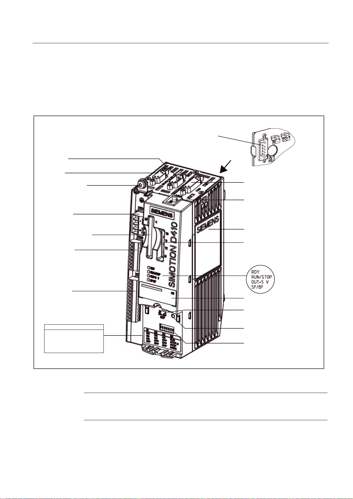
The following figure shows SIMOTION D410 DP with the interfaces and front elements.
3RZHU0RGXOH,QWHUIDFH30,)
;
6HULDOLQWHUIDFHQRIXQFWLRQ
;
352),%86
0VFUHZRQVKLHOG
FRQQHFWLRQ
;
(QFRGHULQWHUIDFH+7/77/66,
;
'5,9(&/L4LQWHUIDFH
;
(OHFWURQLFVSRZHUVXSSO\
&RPSDFW)ODVKbFDUG
;
(3WHUPLQDOVWHPSHUDWXUH
VHQVRUFRQQHFWLRQ
;
'LJLWDOLQSXWVRXWSXWV
6ZLWFKVHWWLQJVRQWKHPRGH
VHOHFWRUVZLWFK
26
6
6
6
21
21
21
2))
21
21
2))
2))
21
2))
2))
2))
581
6723B8
6723
05(6
Figure 1-2 Location of interfaces and front elements in SIMOTION D410 DP
6LGHQDPHSODWH
7770
0HDVXULQJVRFNHWV
/('GLVSOD\V
7\SHSODWH
%23LQWHUIDFH
QRIXQFWLRQ
5(6(7EXWWRQ
0RGHVHOHFWRUVZLWFK
',3VZLWFK
Note
The label underneath the mode selector lists the switch settings for the operating states of
the SIMOTION D410.
D410
Commissioning Manual, 08/2008 Edition
19
Page 20

Description
1.3 SIMOTION D410 DP display
Interfaces
The SIMOTION D410 DP interfaces are described in the following tables.
Table 1-5 SIMOTION D410 interfaces
Interface Description
Digital inputs/outputs
X121
DRIVE-CLiQ interface
X100
PROFIBUS DP interface
X21
Power Module Interface
(PM-IF)
Encoder interface (HTL / TTL
/ SSI)
X23
EP terminals/temperature
sensor connection
X120
Power supply connection
X124
Measuring sockets
T0, T1, T2 and M
12-pin Mini Combicon:
• 4 digital inputs: for connecting switches or proximity sensors
• 4 digital inputs/outputs: for connecting actuators and sensors
8-pin RJ45plus socket to connect DRIVE-CLiQ nodes
9-pin SUB-D socket to connect to PROFIBUS DP
8-pin direct connector to connect to a blocksize power module
15-pin SUB-D socket for connecting HTL, TTL and SSI encoders.
8-pin Mini Combicon for connecting Safety Integrated input terminals
or for connecting temperature sensing via KTY or PTC
4-pin screw terminal connection to connect the 24 V DC load power
supply
Sockets to output analog signals
D410
20 Commissioning Manual, 08/2008 Edition
Page 21
Description
1.3 SIMOTION D410 DP display
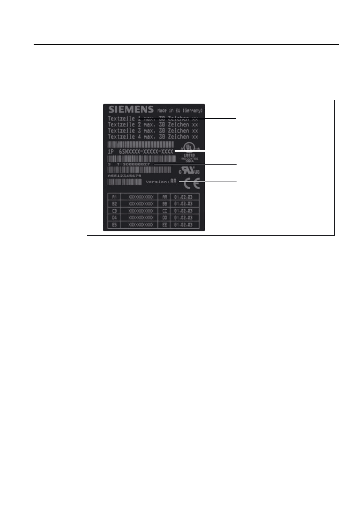
Nameplates
The following figure shows you all the information included on the nameplates located on the
side of the unit.
0RGXOHGHVLJQDWLRQ
2UGHUQXPEHU
6HULDOQXPEHU
+:YHUVLRQ
Figure 1-3 SIMOTION D410 nameplate
D410
Commissioning Manual, 08/2008 Edition
21
Page 22

Description
3$8$$$$
6DFK1U$(
9HUVLRQ
$
''3
1.3 SIMOTION D410 DP display
The following nameplate includes the SIMOTION D410 DP barcode numbers and is located
on the front side of the module.
%DUFRGH0/)%1R$8$$$$
3$8$$$$
%DUFRGH
6DFK1U$(
''3
7\SHGHVLJQDWLRQ
3URGXFWQXPEHU
2UGHUQXPEHU0/)%1R
6SDFHIRUDSSURYDOVLGHQWLILFDWLRQV
9HUVLRQ
5HYLVLRQOHYHO
Figure 1-4 SIMOTION D410 DP nameplate (example)
Note
The contents of the individual nameplate fields on the current module may differ from those
described in this Manual (e.g., updated product status, space for approvals and
identifications, etc.).
D410
22 Commissioning Manual, 08/2008 Edition
Page 23
Description
1.4 SIMOTION D410 PN display
1.4 SIMOTION D410 PN display
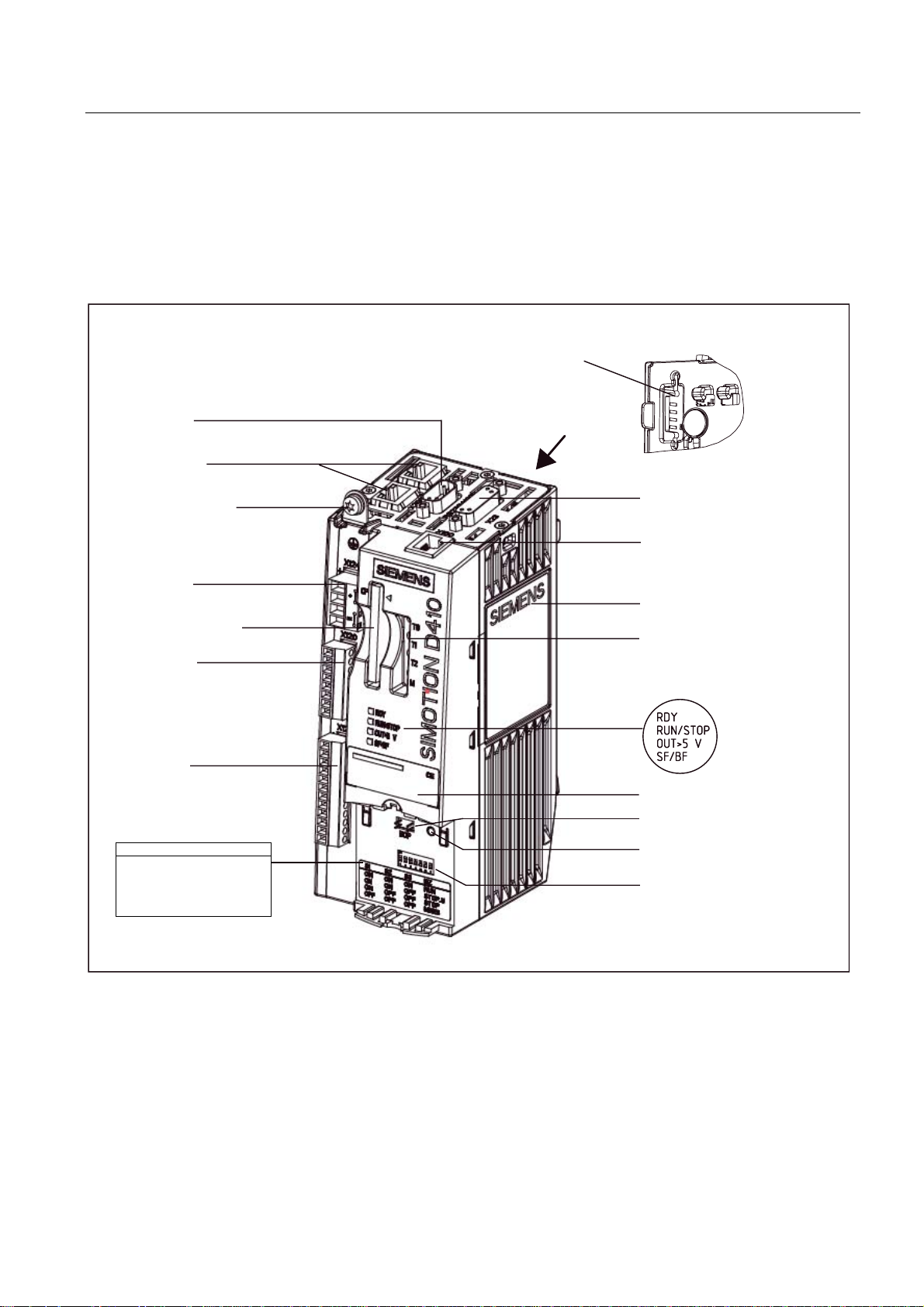
View
The following figure shows SIMOTION D410 PN with the interfaces and front elements.
3RZHU0RGXOH,QWHUIDFH30,)
;
6HULDOLQWHUIDFHQRIXQFWLRQ
;;
352),1(7VRFNHWV
0VFUHZRQVKLHOG
FRQQHFWLRQ
;
(QFRGHULQWHUIDFH+7/77/66,
;
'5,9(&/L4LQWHUIDFH
;
(OHFWURQLFVSRZHUVXSSO\
&RPSDFW)ODVKbFDUG
;
(3WHUPLQDOVWHPSHUDWXUH
VHQVRUFRQQHFWLRQ
;
'LJLWDOLQSXWVRXWSXWV
6ZLWFKVHWWLQJVRQWKHPRGH
VHOHFWRUVZLWFK
6
6
6
21
21
21
2))
21
21
2))
2))
21
2))
2))
2))
26
581
6723B8
6723
05(6
Figure 1-5 Location of interfaces and front elements in SIMOTION D410 PN
6LGHQDPHSODWH
7770
0HDVXULQJVRFNHWV
/('GLVSOD\V
7\SHSODWH
%23LQWHUIDFH
QRIXQFWLRQ
5(6(7EXWWRQ
0RGHVHOHFWRUVZLWFK
',3VZLWFK
D410
Commissioning Manual, 08/2008 Edition
23
Page 24

Description
1.4 SIMOTION D410 PN display
Interfaces
The SIMOTION D410 PN interfaces are described in the following tables.
Table 1-6 SIMOTION D410 interfaces
Interface Description
Digital inputs/outputs
X121
DRIVE-CLiQ interface
X100
PROFINET interface
(ports X200 and X201)
Power Module Interface
(PM-IF)
Encoder interface (HTL / TTL /
SSI)
X23
EP terminals / temperature
sensor connection
X120
Power supply connection
X124
Measuring sockets
T0, T1, T2 and M
12-pin Mini Combicon:
• 4 digital inputs: for connecting switches and proximity sensors
• 4 digital inputs/outputs: for connecting actuators and sensors
8-pin RJ45plus socket to connect DRIVE-CLiQ nodes
8-pin RJ45plus socket to connect to PROFINET
8-pin direct connector to connect to a blocksize power module
15-pin SUB-D socket for connecting HTL, TTL and SSI encoders.
8-pin Mini Combicon for connecting Safety Integrated input
terminals or for connecting temperature sensing via KTY or PTC
4-pin screw terminal connection to connect the 24 V DC load
power supply
Sockets to output analog signals
D410
24 Commissioning Manual, 08/2008 Edition
Page 25

Description
1.4 SIMOTION D410 PN display
Nameplates
The following figure shows you all the information included on the nameplates located on the
side of the unit.
0RGXOHGHVLJQDWLRQ
2UGHUQXPEHU
6HULDOQXPEHU
+:YHUVLRQ
Figure 1-6 SIMOTION D410 nameplate
D410
Commissioning Manual, 08/2008 Edition
25
Page 26

Description
9HUVLRQ
$(
;;;;;;
$8$%$$
'31
$
1.4 SIMOTION D410 PN display
The following nameplate includes the MAC address of the PROFINET interface (ports X200
and X201) and is located on the front side of the module.
'31
$8$%$$
$(
;;;;;;
%DUFRGH0$&DGGUHVV
0$&DGGUHVV
3URGXFWQXPEHU
2UGHUQXPEHU0/)%1R
7\SHGHVLJQDWLRQ
9HUVLRQ
6SDFHIRUDSSURYDOVLGHQWLILFDWLRQV
5HYLVLRQOHYHO
Figure 1-7 SIMOTION PN nameplate (example)
Note
The contents of the individual nameplate fields on the current module may differ from those
described in this Manual (e.g., updated product status, space for approvals and
identifications, etc.).
D410
26 Commissioning Manual, 08/2008 Edition
Page 27
Description
1.5 The CompactFlash card
1.5 The CompactFlash card
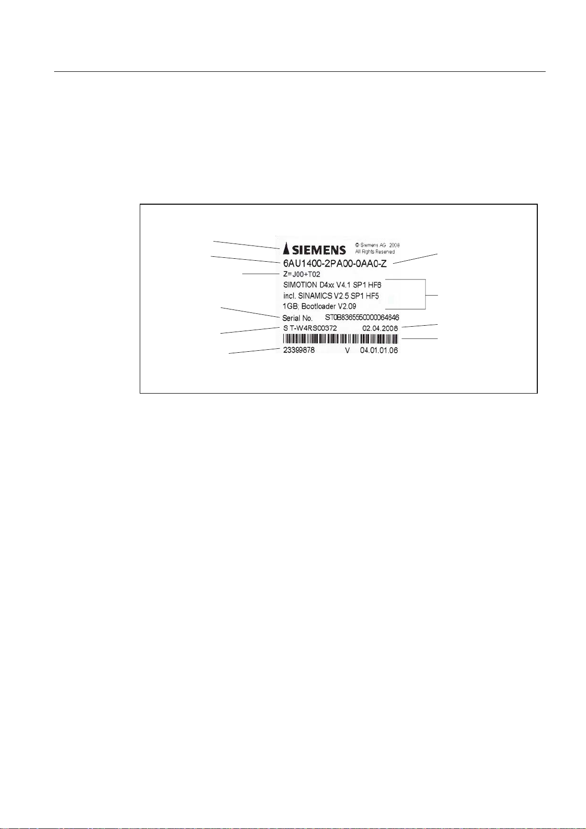
CompactFlash card
The following figure shows you all the information included on the nameplate of the
CompactFlash card (CF card).
3RLQWHUWRVKRZSOXJLQGLUHFWLRQ
RIWKH&)FDUG
2UGHUQXPEHU
/LVWRI=RSWLRQOLFHQVHV
RQWKH&)FDUGXSRQGHOLYHU\
+:VHULHVQXPEHU
RIWKH&)FDUG
8QLTXH,'QXPEHU
'HOLYHU\QRWHQXPEHU
'HVLJQDWLRQRI&)
FDUGZLWK=RSWLRQ
3URGXFWDQGYHUVLRQ
GHVLJQDWLRQ
&DUGFDSDFLW\
%RRWORDGHUYHUVLRQ
3URGXFWLRQGDWH
%DUFRGH
LQFOXGLQJRUGHUQXPEHU
Figure 1-8 CompactFlash card
Pre-installed runtime licenses
For versions V4.1 SP1 HF6 and higher, pre-installed licenses are printed on the type plate of
the CF card as a Z option underneath the order number.
Example with Z option for a combined SIMOTION IT license + 2 TControl licenses:
6AU1400-2PA00-0AA0-Z
Z=J00+T02
A maximum of 7 different Z options are printed on the type plate of the CF card. When there
are more than 7 different Z options, the text "Z = see delivery order" is printed on the CF card
in place of the Z option.
D410
Commissioning Manual, 08/2008 Edition
27
Page 28

Description
1.6 Licensing
Available Z options / licenses for SIMOTION D CF cards
The following Z options are available for SIMOTION D410:
TControl temperature control:
● Txx – TControl license and number (e.g. T03 = 3 TControl licenses)
SIMOTION IT:
● D00 – IT DIAG license
● X00 – OPC XML-DA license
● J00 – Combined license for SIMOTION IT, comprises SIMOTION IT Virtual Machine for
Java applications, SIMOTION IT DIAG and SIMOTION IT OPC XML-DA
Safety functions:
● Fxx - License for SINAMICS Safety Integrated Extended Functions (e.g., F01 = 1 license
for safety functions)
1.6 Licensing
SIMOTION D410 licensing
SIMOTION D410 is a modular drive system for single-axis applications. D410 contains the
Motion Control technology functions for exactly one real axis (speed-controlled, positioning,
synchronized axis or cam). This means that these technology functions do not require an
additional license. It is not possible to increase the number of axes using licenses. Along
with the one real axis, further virtual axes can be configured and loaded.
Licenses are required for runtime functions such as SIMOTION IT DIAG. These can be preinstalled on a CompactFlash card (CF card) or ordered separately.
Additional references
For more information about license management, see the
Manual
. General information about licensing can be found in the
SINAMICS S120 catalog and motors for production machines catalog, PM21 2008
SIMOTION SCOUT Configuring
Motion Control SIMOTION,
.
D410
28 Commissioning Manual, 08/2008 Edition
Page 29

Description
1.7 Safety information
1.7 Safety information
Observe the following safety information when working with SIMOTION D410 and its
components!
CAUTION
The CompactFlash card may only be unplugged and plugged in when SIMOTION D410 is
switched off (zero current)!
CAUTION
The 50 mm clearances above and below the components must be observed. The
ventilation openings may not be covered by connecting cables.
D410
Commissioning Manual, 08/2008 Edition
29
Page 30

Page 31

Commissioning (hardware)
2.1 Prerequisites for commissioning
Prerequisites
Prerequisites for commissioning the SIMOTION D410:
● You have completed installation and the wiring of your system with SIMOTION D410.
● A programming device / PC is available.
Connecting a programming device / PC to SIMOTION D410
You can interconnect the programming device / PC:
● With the PROFIBUS interface of SIMOTION D410 DP (X21 connector) using a
connecting cable.
Information pertaining to cable lengths for PROFIBUS DP is available in the
SIMOTION D410
● With the PROFINET interface of SIMOTION D410 PN (X200 or X201 connector) using a
twisted pair cable.
Manual.
2
Information pertaining to PROFINET communication is available in chapter "Configuring
PROFINET".
System requirements
System requirements for hardware commissioning:
● The programming device must be equipped with a PROFIBUS or Ethernet adapter.
● The programming device / PC must be interconnected with SIMOTION D410 DP
(connector X21) for online communication on PROFIBUS DP.
● The programming device / PC must be interconnected with SIMOTION D410 PN
(connector X200 and 201) for online communication on PROFINET.
● You need a CF adapter on the programming device / PC to write to the Compact Flash
Card (for example, a SIMOTION firmware update).
D410
Commissioning Manual, 08/2008 Edition
31
Page 32
Commissioning (hardware)
2.2 Inserting the Compact Flash card
2.2 Inserting the Compact Flash card
Properties of the CF card
The CF card is mandatory for operation of SIMOTION D410. The SIMOTION kernel and the
drive control software (SINAMICS firmware) are installed on the CF card.
The CompactFlash card must be inserted when you start up SIMOTION D410 in order to
load the SIMOTION kernel.
Procedure
Note
The Compact Flash Card may only be removed and inserted while SIMOTION D410 is in de-
energized state!
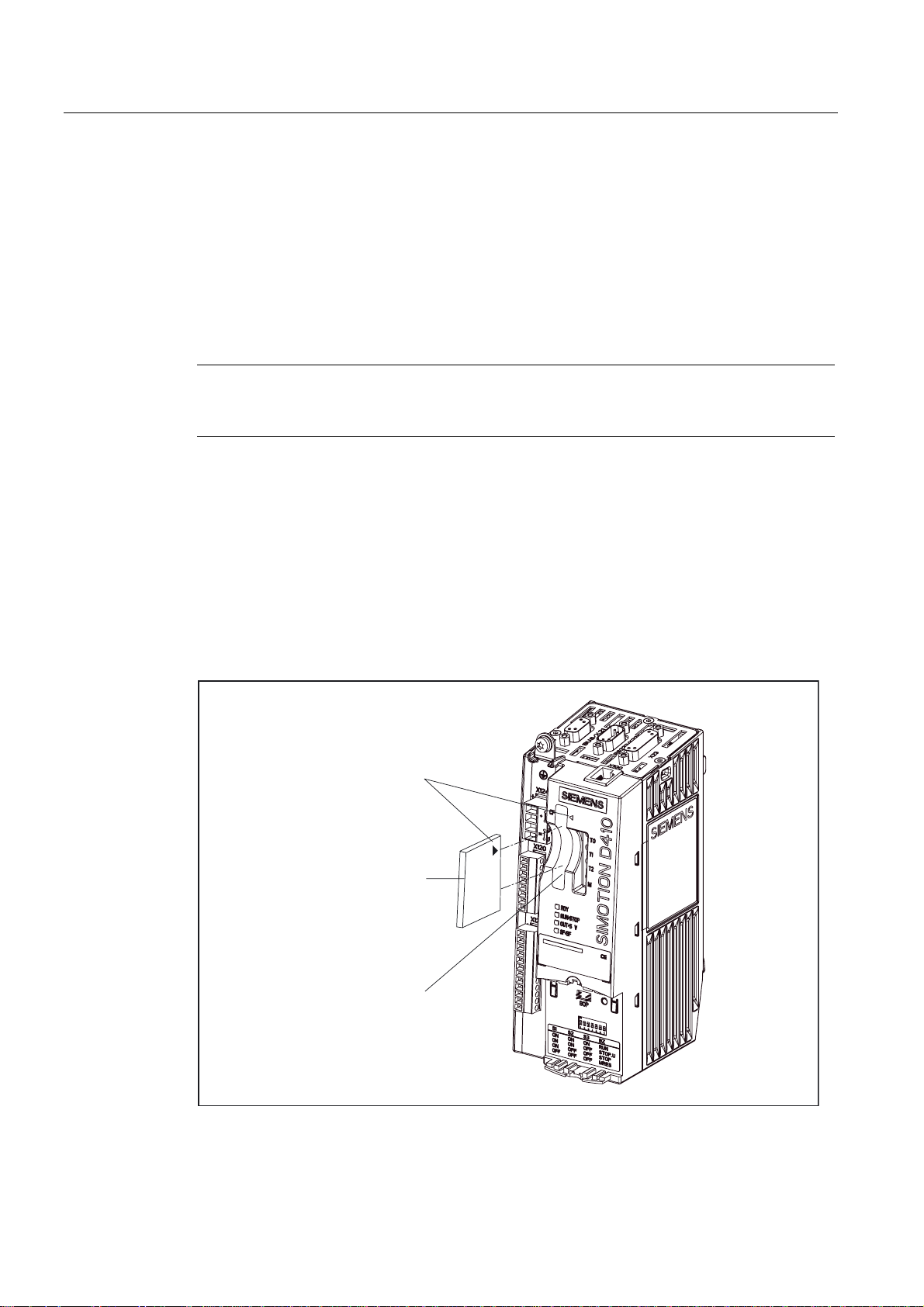
Insert the CompactFlash Card as follows:
1. The insertion direction of the CompactFlash Card is identified by an arrow on the card
and a matching arrow on the slot. Align the arrows when inserting the CompactFlash
Card.
2. Gently push the CompactFlash Card into the card slot of SIMOTION D410 until it
engages. The properly inserted card does not protrude from the SIMOTION D410
housing.
$UURZV
&RPSDFW)ODVK&DUG
6ORWIRU&RPSDFW)ODVK&DUG
Figure 2-1 Inserting the CompactFlash Card
D410
32 Commissioning Manual, 08/2008 Edition
Page 33

Commissioning (hardware)
2.3 Switching on the power supply
2.3 Switching on the power supply
Checking the system
Check the system installation and wiring once again before you switch it on. Observe the
safety-relevant items of the following checklist:
● Have you observed all ESD measures when handling the components?
● Are all connectors properly inserted and interlocked / screwed on?
● Are all components grounded and all shields terminated?
● Have you made allowances for sufficient load capacity of the central power supply?
Switching on the external power supply
Power is supplied to the SIMOTION D410 using an external power supply unit, for example,
using SITOP power supplies (in special circumstances, the SIMOTION D410 can also be
supplied using the PM340 Power Module, see SIMOTION D410 Manual).
CAUTION
It is imperative to prevent the external 24 VDC power supply to SIMOTION D410 from
being interrupted for a duration longer than 3 ms. Operation of SIMOTION D410 is stopped
on expiration of these 3 ms and can only be recovered by cycling power Off > On.
Additional information is available in chapter "User memory concept".
Startup of SIMOTION D410
The startup of SIMOTION D410 is initiated after the power supply is activated:
1. The RDY LED is lit and the red RUN/STOP LED briefly lights up at the beginning of the
startup sequence. These LEDs can be used to monitor the startup sequence. Any errors
are displayed.
2. Startup of the SIMOTION kernel.
3. All DRIVE-CLiQ connections (with SINAMICS S120 Power Module PM340, for example)
Switch on the power supply after having checked off all items of the checklist.
are identified automatically.
Note
Startup of SIMOTION D410 is completed as soon as its RDY LED is lit in green color and
the RUN/STOP LED is lit in yellow or green color.
The SIMOTION D410 is ready for configuring after successful completion of the startup.
D410
Commissioning Manual, 08/2008 Edition
33
Page 34

Commissioning (hardware)
2.4 RESET button
2.4 RESET button
Arrangement
The RESET button is located behind the blanking plate on the SIMOTION D410.
Performing a reset operation
A reset causes the entire system to be reset and requires the system to be ramped-up again.
It is similar to a "Power On Reset" except that the 24 V power supply does not have to be
switched off.
D410
34 Commissioning Manual, 08/2008 Edition
Page 35

Commissioning (hardware)
2.5 User memory concept
2.5 User memory concept
2.5.1 SIMOTION D410 memory model
The following figure provides an overview of the SIMOTION D410 memory model.
3URJUDPPLQJGHYLFH
(66,027,216&287
'RZQORDG
6,027,21b'
&RPSDFW)ODVK&DUG
73V
8VHUGDWD
,3SDUDPHWHUV
'3SDUDPHWHUV
6,027,21NHUQHO
5$0WR520
'VWDUWXS
'VWDUWXS
'VWDUWXS
9RODWLOHGDWD
73V
8VHUGDWD
6,027,21NHUQHO
1RQYRODWLOHGDWD
'LDJQRVWLFVEXIIHU
5HWHQWLYHXVHUDUHD
UHWDLQYDULDEOH
,3SDUDPHWHUV
'3SDUDPHWHUV
$EVROXWHHQFRGHU
RIIVHW
Figure 2-2 SIMOTION D410 memory model
The next chapters provide information pertaining to user memories and to the sequences of
specific user actions.
See also
Properties of the user memories (Page 36)
Operator actions and their impact on user memory (Page 38)
D410
Commissioning Manual, 08/2008 Edition
35
Page 36

Commissioning (hardware)
2.5 User memory concept
2.5.2 Properties of the user memories
Non-volatile data
Non-volatile data is used with the objective of retaining user- and system-relevant data when
SIMOTION D410 is in de-energized state. You will find information about the area that can
be used for non-volatile data in the
SIMOTION SCOUT
Non-volatile data available in SIMOTION devices:
Table 2-1 Content of non-volatile data
Non-volatile data Content
Kernel data
Retain variables
Retain TO Absolute encoder offset
• Last operating state
• IP parameters (IP address, subnet mask, router address)
• DP parameters (PROFIBUS DP address, baud rate)
• Diagnostics buffer
• Variables in the interface or implementation section of a unit declared
with VAR_GLOBAL RETAIN
• Global device variables set with the "RETAIN" attribute
Configuration Manual.
Properties of non-volatile data of SIMOTION D410:
Table 2-2 Properties of non-volatile data
Properties Meaning
Location: Non-volatile data resides in the FRAM of SIMOTION D410.
Backup battery: A backup battery is not required.
Backup time: Unlimited
More information
IP and DP parameters in non-volatile data
The IP and DP parameters are loaded from configuration data on the CompactFlash Card
during startup for use by the SIMOTION device. The SIMOTION D410 can use the
addresses defined in these data to go online. The IP and DP parameters on the
CompactFlash Card are also written to non-volatile memory during startup. The IP and DP
parameters in non-volatile data is retained and used by the SIMOTION device if the system
is restarted with a CompactFlash Card which does not contain any configuration data. The
SIMOTION device can always be made available online if the configuration was downloaded
to the device at least once using SIMOTION SCOUT, or if the SIMOTION device was started
up with Compact Flash Card.
D410
36 Commissioning Manual, 08/2008 Edition
Page 37

Commissioning (hardware)
2.5 User memory concept
Volatile data
Definition of the properties of volatile data:
● Volatile data resides in the RAM area of SIMOTION D410.
● The download data of SIMOTION SCOUT is written to this memory.
● These data is lost after the SIMOTION D410 is shut down.
● Contents of the "volatile data" area:
– SIMOTION kernel
– Technology packages (TP)
– User data (programs, configuration data, parameters)
7DUJHW
GHYLFH
'RZQORDG
8SORDG
5$0WR
520
0LFUR0HPRU\&DUG
&RPSDFW)ODVK&DUG
0HPRU\&DUG
Figure 2-3 Configuration data and system variables on volatile memory
520
FRS\
5$0
ORDGPHPRU\
&RQILJGDWDLQ
581
6\VWHP
YDULDEOHV
&RS\DFWXDOGDWD
WR5$0
QRV\VWHP
YDULDEOHV
&RPPLVVLRQLQJ
1H[W
72UHVWDUW
RULPPHGLDWHO\
&XUUHQW5$0
ZRUNLQJPHPRU\
You can find additional information about memory management in SIMOTION in the
SIMOTION Basic Functions
Function Manual.
D410
Commissioning Manual, 08/2008 Edition
37
Page 38

Commissioning (hardware)
2.5 User memory concept
CompactFlash Card
The CompactFlash Card contains the following data:
● SIMOTION kernel
● Technology packages (TP)
● User data (units, configuration data, parameters, task configuration)
● IP parameters (IP address, subnet mask, router address)
● DP parameters (PROFIBUS DP address, baud rate)
2.5.3 Operator actions and their impact on user memory
The next section describes the user actions identified in the "SIMOTION D410 memory
model" by arrows and their impact on user memory.
Download SIMOTION SCOUT
The "Download" command transfers the following data from the Engineering System to the
"volatile data" area:
● User data (units, configuration data, parameters, task configuration)
● Technology packages
The IP and DP parameters are furthermore saved to the "non-volatile data" area. The retain
variables are initialized with their start values. This however, depends on the settings in
SIMOTION SCOUT. Volatile data is lost if you shut down the SIMOTION D410 module after
the download.
Copy RAM to ROM
The "Copy RAM to ROM" command is used on the ES to save the following data to the
CompactFlash Card:
● Technology packages and user data (units, configuration data, parameters, task
● Actual values are copied to the "volatile data" area, depending on the settings in
configuration) of the "volatile data" area
SIMOTION SCOUT
Note
The "Copy RAM to ROM" command does not save the actual values of the retain
variables to the CompactFlash Card:
D410
38 Commissioning Manual, 08/2008 Edition
Page 39

Commissioning (hardware)
2.5 User memory concept
Startup of SIMOTION D410
The SIMOTION kernel is loaded from the CompactFlash Card to the "volatile data" area
during the startup of SIMOTION D410.
Volatile data is lost if you shut down the SIMOTION D410 module after the download. Data
loaded from the CompactFlash Card at the next restart:
● The technology packages and user data to the "volatile data" area
● IP and DP parameters to the "non-volatile data" area
Backup of non-volatile data
The "_savePersistentMemoryData" system function is used to save the contents of nonvolatile data to the CompactFlash Card. This backup prevents the retain variables and the
absolute encoder position from being lost if a component is replaced.
The backup copy is saved to the "PMEMORY.XML" backup file in the "USER/SIMOTION"
folder. On system side it is always ensured that a consistent overall image of the non-volatile
data is available at the next restart, even if there is a power failure during backup. An already
existing backup file is renamed to "PMEMORY.BAK" before a new backup file is generated.
If the backup to this new file fails (for example, due to insufficient storage capacity of the
CompactFlash Card), the existing backup file is used in the next attempt to restore the
content of non-volatile data. The backup file is deleted if the new file was successfully
created.
NOTICE
An absolute encoder overflow after "_savePersistentMemoryData" was executed indicates
that the restored non-volatile data contains an incorrect actual position value. The encoder
must be referenced again (absolute encoder adjustment)!
D410
Commissioning Manual, 08/2008 Edition
39
Page 40

Commissioning (hardware)
2.5 User memory concept
Startup and non-volatile data
The table below describes the startup situations which may develop in terms of the nonvolatile data and how to handle such situations.
Table 2-3 Startup situations with non-volatile data
Situa
tion
1 Valid contents of non-volatile data. Startup of SIMOTION D410 with the non-volatile data.
2 Invalid contents in non-volatile data, and neither a backup
3 Invalid contents in non-volatile data. A backup file
4 Invalid contents in non-volatile data and in the backup file,
5 Invalid contents in non-volatile data and in the backup file,
Initial condition Result
The PROFIBUS address in non-volatile data is
therefore valid, for example.
SIMOTION D410 copies the factory defaults to its nonfile (PMEMORY.XML), nor a backup copy
(PMEMORY.BAK) exists.
(PMEMORY.XML) with valid contents is available.
and a backup copy (PMEMORY.BAK) is not available.
and a backup copy (PMEMORY.BAK) with valid contents
is available.
volatile data and restarts using this data. The default
PROFIBUS address is valid in this case, for example.
SIMOTION D410 copies the contents of the backup file
to its non-volatile data and starts using this data.
SIMOTION D410 copies the factory defaults to its non-
volatile data and restarts using this data. The default
PROFIBUS address is valid in this case, for example.
SIMOTION D410 copies the contents of the backup file
to its non-volatile data and starts using this data.
Diagnostics of non-volatile data
Users can determine the status of non-volatile data by reading the diagnostics buffer and the
system variable.
The following message events are entered once in the diagnostics buffer when they occur:
Table 2-4 Messages of the diagnostics buffer
Entry Meaning To correct or avoid errors
Non-volatile data loaded from file
(Persistent Data File Loading done)
Non-volatile data loaded from the backup file
(Persistent Data Backup File Loading done)
Error while loading non-volatile data from a
file
(Persistent Data File Loading Failure)
D410
Non-volatile data successfully restored
from the backup file to the
CompactFlash Card.
Non-volatile data successfully restored
from the backup copy to the
CompactFlash Card.
Backup file or backup copy could not be
loaded.
Possible causes:
• Backup file or backup copy not
available
• Invalid data in backup file
-
-
Use the
"_savePersistentMemoryData"
system function to generate a
backup file with valid contents.
40 Commissioning Manual, 08/2008 Edition
Page 41

Commissioning (hardware)
2.5 User memory concept
See also
Refer to the
SIMOTION SCOUT
Configuration Manual for information about how to read out
the contents of the diagnostic buffer.
System variable "persistentMemoryPowerMonitoring.persistentDataState" indicates the
status of non-volatile data after startup:
Table 2-5 Status of non-volatile data after startup
Status Meaning
FROM_RAM (1) Non-volatile data is activated in the SIMOTION device
FROM_FILE (2) Non-volatile data was restored from the backup file
FROM_BACKUP (3) Non-volatile data was restored from the backup copy
INVALID (4) Non-volatile data and data in the backup file / backup copy are invalid, or do
not exist, or were deleted.
The SIMOTION device copied the factory defaults to its non-volatile data
and started using this data.
SIMOTION D410 memory model (Page 35)
D410
Commissioning Manual, 08/2008 Edition
41
Page 42

Page 43

Configuring SIMOTION D410
3.1 Software requirements
SIMOTION SCOUT Engineering System
The SIMOTION SCOUT Engineering System must be installed on your programming device
/ PC in order to commission the SIMOTION D410. Observe the information on the current
"SIMOTION SCOUT" CD.
For information on how to install SIMOTION SCOUT on your programming device / PC, refer
SIMOTION SCOUT
to the
3.2 Inserting SIMOTION D410 into a project
Creating a project and configuring the programming device / PC interface
Proceed as follows in order to create a project in SIMOTION SCOUT and to insert a
SIMOTION D410:
Configuration Manual.
3
1. Select the "Project > New..." menu.
2. Enter a name for your project in the "New Project" dialog box and confirm your entry with
"OK".
A new folder is generated in the Project Navigator and assigned the name of the project.
3. Double-click "Create new device" in the Project Navigator. The "Create New Device"
dialog box opens. Select D410 from the "CPU type" field and the characteristic of your
module (D410 DP or D410 PN) from the "Variant" field. Confirm with "OK".
4. The "Properties" dialog box of the (PROFIBUS or PROFINET) interface opens where you
set up the connection to the programming device / PC according to the module
characteristics.
D410
Commissioning Manual, 08/2008 Edition
43
Page 44

Configuring SIMOTION D410
3.2 Inserting SIMOTION D410 into a project
Communication with the programming device / PC via PROFIBUS (only for D410 DP)
1. Select the PROFIBUS interface from the "Properties - PROFIBUS/MPI" dialog box and
confirm your selection with "OK".
2. The connection to the programming device / PC is activated automatically and HW Config
opens.
Note
The active state setting of the connection to the programming device / PC is only
visualized in NetPro!
Interconnection with the programming device / PC on PROFINET (only for D410 DN)
The "Properties - Ethernet Interface" dialog box is open.
Figure 3-1 Properties of the Ethernet interface
Program the following parameters in the "Properties - Ethernet Interface" dialog box:
1. Click "New".
The "New Subnet Industrial Ethernet" dialog box opens. Rename the new subnet, or
accept the default name by clicking "OK".
2. Select the new Ethernet subnet which is now displayed in the "Properties - Ethernet
Interface" dialog box.
3. Define your addresses in the "IP address" and "Subnet mask" fields of the "Properties -
Ethernet Interface" dialog box. Change to the "Network node" field and define whether
you are going to use a router and, if yes, enter the router address. Confirm with "OK".
4. Select the PROFINET interface from the "Properties" dialog box and confirm your
selection with "OK".
5. The connection to the programming device / PC is activated automatically and HW Config
opens.
D410
44 Commissioning Manual, 08/2008 Edition
Page 45

Configuring SIMOTION D410
3.2 Inserting SIMOTION D410 into a project
Note
The active state setting of the connection to the programming device / PC is only
visualized in NetPro!
Representation in HW Config
SIMOTION D410 is represented in HW Config.
Figure 3-2 Image of a SIMOTION D410 PN in HW Config
D410
Commissioning Manual, 08/2008 Edition
45
Page 46

Configuring SIMOTION D410
3.3 Configuring the PROFIBUS DP interface (only D410 DP)
3.3 Configuring the PROFIBUS DP interface (only D410 DP)
3.3.1 General information about PROFIBUS DP communication
Definition of PROFIBUS DP
PROFIBUS DP is an international, open field bus standard specified in the European field
bus Standard EN 50170 Part 2. PROFIBUS DP is optimized for high-speed, time-sensitive
data transfer at field level.
Components communicating on PROFIBUS DP are classified as master and slave
components.
● Master (active bus node)
Components representing a bus master determine the data traffic on the bus and are
therefore also referred to as active bus nodes.
● Slaves (passive bus nodes)
These devices may only receive, acknowledge and return messages to the master if
requested by the master.
Examples: SINAMICS drives, I/O modules
Note
If a SIMOTION D410 DP is operated as a passive PROFIBUS I-slave, the display,
measuring functions and controller optimization engineering functions will be very slow. If
possible, use the "active I-slave" setting for local commissioning (which does mean that an
equidistance is no longer possible) and for complete commissioning, switch to "passive Islave".
Additional references
You will find additional information about PROFIBUS DP in the
System Manual.
SIMOTION Communication
D410
46 Commissioning Manual, 08/2008 Edition
Page 47

Configuring SIMOTION D410
3.3 Configuring the PROFIBUS DP interface (only D410 DP)
3.3.2 Assignment of the PROFIBUS addresses in HW Config
Assigning PROFIBUS addresses
Assign a PROFIBUS address to all devices before you start networking these in order to
enable intercommunication.
Note
All PROFIBUS addresses you assign must be unique on the PROFIBUS subnet.
Information pertaining to the rules of communication on the PROFIBUS subnet is available in
SIMOTION D410
the
Manual.
Define the PROFIBUS address separately for each device on your programming device / PC
in HW Config. Certain PROFIBUS DP slaves are equipped with an address switch.
Note
The PROFIBUS addresses set at the devices using these switches must correspond with the
address settings in HW Config.
Recommendation for PROFIBUS addresses
Reserve PROFIBUS address "0" for a service programming device and "1" for a service HMI
device which are connected to the subnet as required.
Recommended PROFIBUS address setting for SIMOTION D410 in case of replacement or
service:
Reserve address "2" for a SIMOTION D410. This prevents redundancy of the addresses
after SIMOTION D410 is installed in the subnet with default settings (for example, when
replacing a SIMOTION D410). Assign addresses higher than "2" to any additional devices on
the subnet.
D410
Commissioning Manual, 08/2008 Edition
47
Page 48

Configuring SIMOTION D410
3.3 Configuring the PROFIBUS DP interface (only D410 DP)
3.3.3 Operating SIMOTION D410 on PROFIBUS DP.
PROFIBUS DP interface (X21)
SIMOTION D410 provides an interface for connecting to PROFIBUS DP. The interface
supports transmission rates up to 12 Mbit/s.
The PROFIBUS DP interface can be operated as:
● DP slave, isochronous
● DP master, isochronous
● DP slave, not isochronous
● DP master, not isochronous
Both PROFIBUS DP interfaces are set by default for operation as master at address 2 at a
transmission rate of 1.5 Mbit/s. The PROFIBUS DP network is automatically detected and
generated for this setting.
However, you can select other settings. Such user-specific settings must be configured in
HW Config and NetPro.
3.3.4 Creating a new PROFIBUS DP subnet
The SIMOTION D410 device is networked using SIMOTION SCOUT. Set up your userspecific bus parameters for the PROFIBUS interface when you configure the network.
Note
The actions outlined below only need to be taken if you have not selected an interface when
integrating SIMOTION D410 into the project (cf. chapter "Integrating SIMOTION D410 into a
project").
Next, interconnect the programming device / PC using NetPro with the device, see the
chapter "Configuring the programming device / PC interface".
1. Double-click the "D410" entry in the Project Navigator in order to open HW Config.
2. Double-click the DP/MPI interface in the SIMOTION D410 representation in HW Config.
The "Properties - DP/MPI" dialog box opens.
3. Click "Properties" in the "General" tab to open the "PROFIBUS interface DP/MPI" dialog
box.
4. Click "New" to open the "Properties - New PROFIBUS Subnet" dialog box.
5. Name the new subnet, and then enter its properties in the "Network settings" tab, for
example, the transmission rate.
6. Click "OK" to accept the settings.
The new subnet is now displayed in the "Properties - PROFIBUS interface DP/MPI"
dialog box and is ready for being interconnected with the PROFIBUS DP interface.
7. Save and compile the changes.
The PROFIBUS subnet you created is displayed as a graphic object in HW Config.
D410
48 Commissioning Manual, 08/2008 Edition
Page 49

Configuring SIMOTION D410
3.3 Configuring the PROFIBUS DP interface (only D410 DP)
3.3.5 Setting the DP cycle and system cycle clocks
All system clocks for SIMOTION D410 DP are based on the DP cycle of SINAMICS
Integrated, which must be set in HW Config.
Double-click the SINAMICS block at the integrated PROFIBUS. The "DP Slave Properties"
dialog box opens. You can synchronize the DP cycle of SINAMICS Integrated in the
"Isochronous mode" tab.
Table 3-1 Range of values for SIMOTION D410 DP
DP cycle: ≥ 1 ms
Resolution: 0.125 ms
The PROFIBUS DP interface of the SIMOTION D410 DP supports operation at a DP cycle
time ≥ 1 ms, at a resolution of 0.125 ms. SINAMICS Integrated always runs in isochronous
mode. The cyclic tasks of SIMOTION are therefore always in synchronism with
SINAMICS Integrated.
The set DP cycle of SINAMICS Integrated is displayed as "Bus cycle" in the "System Clocks
- D410..." dialog box in SIMOTION SCOUT. Select the SIMOTION D410 DP in the project
tree, and then select the "Set system clocks" option in the "Target system" > "Expert" menu.
The table below shows the ratios you can set for the system clocks of SIMOTION D410 DP
based on the DP cycle.
Table 3-2 Possible factors between the system cycle clocks
Bus cycle: Servo cycle clock Servo cycle clock: IPO
cycle
1 ... 4, 6, 8 1 … 6 2 … 64
IPO cycle: IPO2 cycle
The minimum configurable length of the servo cycle is 1 ms. In conjunction with technology
objects, a minimum servo cycle of 2 ms is recommended.
If you programmed the PROFIBUS DP interface for operation in isochronous master mode,
you must synchronize its DP cycle with the DP cycle of SINAMICS Integrated in HW Config.
The timebase for the system clocks is generated internally if the DP interface is operated in
isochronous or non-isochronous master mode. SIMOTION D410 does not have to
synchronize itself with an external cycle.
The PROFIBUS DP interface can also be operated in isochronous slave mode. In this
constellation system clocks are based on the clock signals received at the slave interface. A
substitute clock of a duration equivalent to the configured clock is generated internally if the
isochronous slave interface has not received a clock signal.
The clock settings are included in the project download to SIMOTION D410 DP and are
adjusted according to specification.
At a PROFIBUS DP interface operated in isochronous slave mode you can also step down
the clock ratio for synchronization with SINAMICS Integrated. This reduction of the clock
ratio at the isochronous slave interface for synchronization with SINAMICS Integrated allows
the operation of a DP cycle at the slave interface which is equivalent to an integer multiple
SINAMICS Integrated. You set up this reduction by configuring the SINAMICS Integrated
and DP interface cycles in HW Config. The rule is checked in HW Config.
D410
Commissioning Manual, 08/2008 Edition
49
Page 50

Configuring SIMOTION D410
3.3 Configuring the PROFIBUS DP interface (only D410 DP)
3.3.6 Rules for SIMOTION D410 DP
Rules for synchronizing the system clocks
You must conform to the following rules when setting the DP cycle and SINAMICS clocks:
1. The DP cycle must be an integer multiple of the current controller cycle. Error A01902 (2)
is reported in the drive if this rule is violated.
2. The master application cycle (T mapc), which corresponds to the servo cycle, must be an
integer multiple of the speed controller cycle. Error A01902 (7) is reported in the drive if
this rule is violated. The smallest-possible T mapc so results from the smallest common
multiple of the DP cycle and the speed controller cycle.
If the master application cycle = 1, this means that the DP cycle is also an integer multiple
of the speed controller cycle.
3. The DP cycle must be an integer multiple of the basic cycles r0110[x] (DRIVE-CLiQ basic
sampling rates). Error A01902 (13) is reported in the drive if this rule is violated.
Note
In addition to the rules mentioned, also observe the rules outlined below. These rules apply
both to SIMOTION D410 DP and to SIMOTION D410 PN!
An overview of errors reported in SINAMICS Integrated is provided in the SINAMICS S
Parameter Manual
D410
50 Commissioning Manual, 08/2008 Edition
Page 51

Configuring SIMOTION D410
3.3 Configuring the PROFIBUS DP interface (only D410 DP)
Rules for SIMOTION D410 DP
The general rule for SIMOTION D410 specifies that the DP cycle (D410 DP) forms the basic
clock of the cycle system. All cycles longer than this basic clock must be an integer multiple
of the basic clock.
This rule also applies to SINAMICS cycles, if one of the successive cycles is longer than the
basic clock:
● Speed controller p115[1]
● Flow controller p115[2]
● Setpoint channel p115[3]
● Position controller p115[4]
● Positioning p115[5]
● Technology controller (p0115[6])
● Onboard I/O p0799
● Terminal module I/O p4099
The corresponding cycle must be an integer multiple of the basic clock.
If any change to the DP cycle violates this rule you must also change the SINAMICS cycles.
In order to change the cycles in the Expert list of SIMOTION SCOUT, select the
"Control_Unit" from "SINAMICS_Integrated" in the Project Navigator, and then open the
"Expert List" by selecting the "Expert" command from the shortcut menu.
Example: A default value of 4 ms is set at the SINAMICS setpoint channel. If setting a DP
cycle of 3 ms you must set an integer multiple value as required at the setpoint channel, for
example, 3 ms or 6 ms.
D410
Commissioning Manual, 08/2008 Edition
51
Page 52

Configuring SIMOTION D410
3.4 Configuring PROFINET (only for D410 PN)
3.4 Configuring PROFINET (only for D410 PN)
3.4.1 General information about PROFINET communication
Overview
PROFINET is an open component-based industrial communication system using Ethernet
(IEC 61158) for distributed automation systems.
The PROFINET interface supports operation of SIMOTION D410 PN as IO controller and/or
as intelligent device.
PROFINET distinguishes between the controller and its assigned devices. Controller and
devices form a PROFINET IO system, comparable to a master-slave system on PROFIBUS.
SIMOTION D410 PN supports the following PROFINET communication methods:
● RT
● IRT
With IRT, a distinction is made between IRT with high flexibility and IRT with high
performance.
Additional references
Additional information pertaining to PROFINET communication is available in the
Communication System Manual
SIMOTION
.
D410
52 Commissioning Manual, 08/2008 Edition
Page 53

Configuring SIMOTION D410
3.4 Configuring PROFINET (only for D410 PN)
3.4.2 Operating SIMOTION D410 PN on PROFINET
PROFINET interfaces (X200, X201)
SIMOTION D410 PN provides a dual-port PROFINET interface (X200 and X201). The
interface supports transmission rates as high as 100 Mbit/s. It can also be operated
isochronous and equidistant. The autocrossing functionality means both crossed and
uncrossed cables can be used
A port has two integrated LEDs, a green LED and an orange LED. The following LED states
can occur:
Table 3-3 LED states of the LED on the port of the PROFINET interface
LEDs State Meaning
Green LED off No connection to an active partner exists.
LED on A connection to an active partner exists.
Orange LED off No data is being exchanged.
LED flashing Data is being exchanged over the port.
The LED flashes irregularly depending on the data
exchange,
i.e. the LED does not flash with a specific frequency.
Properties of PROFINET on SIMOTION D410 PN
SIMOTION D410 PN on PROFINET supports the following properties
● PROFINET specifies operation at 100 Mbit/s.
● The minimum send cycle is 0.5 ms, and the maximum is 4 ms.
● The setting accuracy for the send cycle is 125 μs.
The use of cycle reduction is possible for the D410. Detailed information concerning cycle
reduction is available in the SIMOTION SCOUT Communication System Manual.
D410
Commissioning Manual, 08/2008 Edition
53
Page 54

Configuring SIMOTION D410
3.4 Configuring PROFINET (only for D410 PN)
Initializing SIMOTION D410
SIMOTION D410 must be assigned an IP address and a device name in order to enable
downloading of the project. This is performed online on the SIMOTION device using the socalled "node initialization". To perform the node initialization, the programming device / PC
must be connected with the SIMOTION D410 PN. SIMOTION SCOUT must be open.
1. Click the "Reachable nodes" button on the SIMOTION SCOUT toolbar. The newly
opened "Reachable nodes" window shows the SIMOTION D410 device as "bus node"
with the address 0.0.0.0 and a name.
2. Select the "Bus node" entry and open the "Edit Ethernet node..." function in the context
menu. The "Edit Ethernet Node" dialog box opens.
3. Enter a name in the "Device name" field.
4. Click the "Assign name" button and confirm the displayed message with "OK."
5. Enter an appropriate IP address for the Ethernet subnet in the "IP address" field.
6. Enter an appropriate subnet mask for the Ethernet subnet in the "Subnet mask" field.
7. If required, enter the data for a network gateway.
8. Click "Assign IP Configuration". The entered data is assigned to the SIMOTION device.
9. Confirm the displayed message with "OK".
10. Click the "Close" button to close the "Edit Ethernet Node" window.
11. Click the "Update" button in the "Reachable Nodes" window. The SIMOTION D410
device is now displayed as "Geraet_01" with the type designation of the device and the
assigned IP address.
12. Click the "Close" button to close the "Reachable Nodes" window.
D410
54 Commissioning Manual, 08/2008 Edition
Page 55
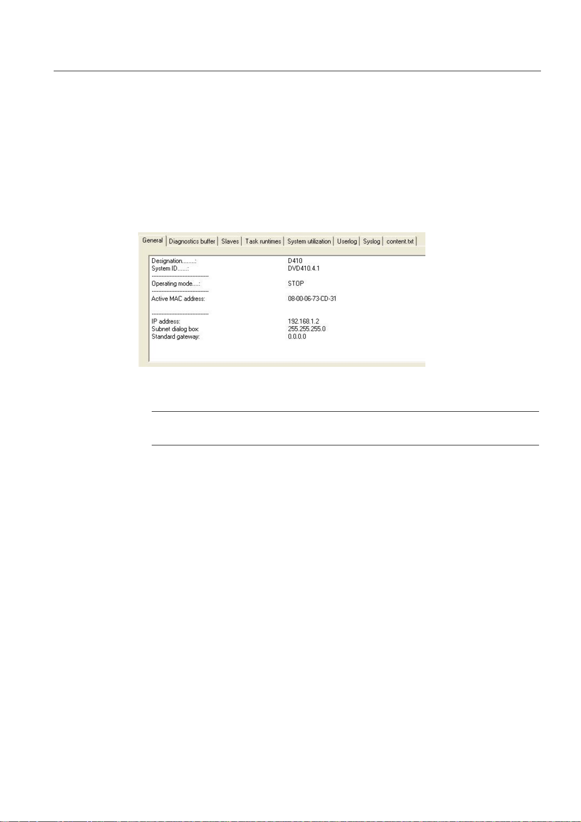
Configuring SIMOTION D410
3.4 Configuring PROFINET (only for D410 PN)
Reading the IP address
To fetch the IP address, the SIMOTION SCOUT must be in online mode.
The IP address of SIMOTION D410 PN can be viewed in SIMOTION SCOUT as follows:
1. Establish an online connection to the SIMOTION D410.
2. Right-click the SIMOTION device in SIMOTION SCOUT.
3. Select the "Target device > Device Diagnostics" command from the shortcut menu.
The address is displayed as follows, for example:
Figure 3-3 Reading the IP address
Note
The MAC address is available on the rating plate on the front panel of the module.
Changing the IP address, device name, network gateway
Set the IP address, the subnet mask and, if necessary, the data for a gateway (router
address) in order to enable communication over PROFINET with SIMOTION D410.
If you want to change the properties in the PROFINET subnet, you can change them using
the "Reachable nodes" function in SIMOTION SCOUT or in the HW Config.
The "Reachable nodes" function with SIMOTION SCOUT is described in the "SIMOTION
D410 initialization" section.
To configure and transfer the properties in HW Config, proceed as follows:
1. Open your project in SIMOTION SCOUT.
2. Open HW Config. Double-click the PROFINET interface to open the "Properties" dialog
box.
3. Click "Properties". The "Properties - Ethernet Interface" dialog box opens.
4. Click "New". The "New Subnet Industrial Ethernet" dialog box opens. Rename the new
subnet, or accept the default name by clicking "OK".
5. Select the new Ethernet subnet which is now displayed in the "Properties - Ethernet
Interface" dialog box.
D410
Commissioning Manual, 08/2008 Edition
55
Page 56

Configuring SIMOTION D410
3.4 Configuring PROFINET (only for D410 PN)
6. Define your addresses in the "IP address" and "Subnet mask" fields of the "Properties Ethernet Interface" dialog box. Change to the "Network node" field and define whether
you are going to use a router and, if yes, enter the router address. Confirm with "OK".
7. Close the "Properties" dialog by clicking "OK".
8. Save and compile the modified hardware configuration.
9. Download the new hardware configuration on PROFINET to your SIMOTION D410.
3.4.3 Setting the send cycles and system clocks
Prerequisite
If, for the PROFINET interface, IRT (high performance) is not configured as the RT class, but
no data is being transferred (no Controller-Controller cross-traffic, or no synchronized IO
device in the internal IO system), the DP cycle of SINAMICS Integrated forms the basis of all
clock settings for SIMOTION D410 PN.
Setting the DP cycle in HW Config
Set the DP cycle of SINAMICS Integrated in HW Config. Double-click the SINAMICS block at
the integrated PROFIBUS. The "DP Slave Properties" dialog box opens. You can
synchronize the DP cycle of SINAMICS Integrated in the "Isochronous mode" tab.
Table 3-4 Range of values for SIMOTION D410 PN
DP cycle: ≥ 1 ms
Resolution: 0.125 ms
SINAMICS Integrated always operates in isochronous mode. The cyclic tasks of SIMOTION
are therefore always in synchronism with SINAMICS Integrated.
D410
56 Commissioning Manual, 08/2008 Edition
Page 57

Configuring SIMOTION D410
3.4 Configuring PROFINET (only for D410 PN)
Setting the send cycle in HW Config
The PROFINET send cycle always forms the basis of the SIMOTION cycles if RT class IRT
is set and data is in actual fact transferred. Set the send cycle in the "Domain Management"
dialog box of HW Config. Open this dialog by selecting the "Edit" > "PROFINET IO" >
"Domain Management ..." command in HW Config.
The set PROFINET send cycle is displayed in SIMOTION SCOUT as "Bus cycle" in the
"System Clocks - D410..." dialog box. Select the SIMOTION D410 PN in the project tree, and
then select the "Set system clocks" option in the "Target system" > "Expert" menu.
The PROFINET interface supports send cycle times within the range 0.5 ms < send cycle <
4 ms. The maximum configurable resolution is 0.125 ms.
The table below shows which ratios you can set for the system clocks of SIMOTION D410
PN based on the DP cycle of SINAMICS Integrated or on the PROFINET send cycle.
Table 3-5 Possible factors for setting the system clocks
DP cycle / send cycle: Servo cycle clock Servo cycle clock: IPO
cycle
1 ... 4, 6, 8 1 ... 6 2 ... 64
IPO cycle: IPO2 cycle
The minimum configurable length of the servo cycle is 1 ms. In conjunction with technology
objects, a minimum servo cycle of 2 ms is recommended.
D410
Commissioning Manual, 08/2008 Edition
57
Page 58

Configuring SIMOTION D410
3.4 Configuring PROFINET (only for D410 PN)
3.4.4 Rules for SIMOTION D410 PN
Rules for using the PROFINET send cycle
If the PROFINET send cycle is the basis for the cycles, ensure that the DP cycle of the
SINAMICS Integrated and the servo cycle are equal.
The timebase for the system clocks are generated internally if the PROFINET interface is not
operated with RT class IRT with high performance or IRT with high performance is set, but
no data is being transferred. This also applies if the PROFINET interface is operated as
synchronization master with RT class IRT with high performance and data is being
transferred. The SIMOTION device does not have to synchronize itself with an external
cycle.
The basis for system clocks is derived from the clock signals received at the PROFINET
interface if this interface is operated as synchronization slave with RT class IRT with high
performance. The SIMOTION device does not have to synchronize itself with this external
clock.
A substitute clock of a duration equivalent to the configured clock is generated internally if
the PROFINET interface has not received a clock signal.
The clock settings are included in the project download to the SIMOTION device and are
adjusted according to specification.
D410
58 Commissioning Manual, 08/2008 Edition
Page 59

Configuring SIMOTION D410
3.4 Configuring PROFINET (only for D410 PN)
Rules for SIMOTION D410 PN
The general rule for SIMOTION D410 specifies that the send cycle (D410 PN) forms the
basic clock of the cycle system. All cycles longer than this basic clock must be an integer
multiple of the basic clock.
This rule also applies to SINAMICS cycles, if one of the successive cycles is longer than the
basic clock:
● Speed controller p115[1]
● Flow controller p115[2]
● Setpoint channel p115[3]
● Position controller p115[4]
● Positioning p115[5]
● Technology controller (p0115[6])
● Onboard I/O p0799
● Terminal module I/O p4099
The corresponding cycle must be an integer multiple of the basic clock.
If any change to the send cycle violates this rule you must also change the SINAMICS
cycles. In order to change the cycles in the Expert list of SIMOTION SCOUT, select the
"Control_Unit" from "SINAMICS_Integrated" in the Project Navigator, and then open the
"Expert List" by selecting the "Expert" command from the shortcut menu.
Example: A default value of 4 ms is set at the SINAMICS setpoint channel. If setting a DP
cycle of 3 ms you must set an integer multiple value as required at the setpoint channel, for
example, 3 ms or 6 ms.
Note
An overview of errors reported in SINAMICS Integrated is provided in the SINAMICS S
Parameter Manual
D410
Commissioning Manual, 08/2008 Edition
59
Page 60

Page 61

Commissioning (software)
4.1 Overview of commissioning
Prerequisites
Prerequisites for commissioning the SIMOTION D410:
● The system has been connected and wired.
● The SIMOTION D410 is switched on and started up (STOP state).
● SIMOTION SCOUT (with integrated STARTER) has been installed and started on the
programming device / PC.
● Communication between the SIMOTION D410 and the programming device / PC is
configured.
● You have created a project and installed a SIMOTION D410 in the project.
NOTICE
For the SIMOTION D410, a reset of the drive must not be set using the expert list of the
control unit in the p972 parameter (drive unit reset). This causes SIMOTION D410
malfunction, the RDY, RUN/STOP and SF/BF LEDs glow red. In this fault situation, the
SIMOTION D410 must be switched off and on again.
4
Commissioning steps
This chapter describes the steps in configuring the plant and testing the configured standalone drive and axis. The steps in commissioning are listed below in the order as
recommended:
1. Configuring SINAMICS Integrated
The integrated drive SINAMICS Integrated can be configured in offline or online mode:
– Offline configuration
All components and their order number must be known for the offline configuration.
– Online configuration
The configuration in online mode allows you to upload all information of the connected
DRIVE-CLiQ components to your user project.
D410
Commissioning Manual, 08/2008 Edition
61
Page 62

Commissioning (software)
4.2 Configuring the system in offline mode
2. Creating an axis
3. Using the digital I/O
4. Optionally, use TMx, DMC20 or other encoders
5. Testing the configured drive
6. Testing the configured axis
Observe the corresponding references.
4.2 Configuring the system in offline mode
4.2.1 Overview
Prerequisites for offline configuration
● All components and their order number must be known for the offline configuration.
Procedure
● You created a project in SIMOTION SCOUT and added a SIMOTION D410 to the project.
● You configured the communication between the programming device / PC and
SIMOTION D410.
Steps involved in offline configuring:
● Calling the Drive Wizard
● Configuring the components
● Aligning the HW Config
● Downloading the project to SIMOTION D410
Note
You can configure all available terminal modules such as TM15 in the course of the
offline configuration, for example.
D410
62 Commissioning Manual, 08/2008 Edition
Page 63

Commissioning (software)
4.2 Configuring the system in offline mode
4.2.2 Accessing the drive wizard
Integrated drive
SIMOTION D410 features an integrated SINAMICS S120 drive (control unit) which is
automatically included when you insert the SIMOTION D410 in the Project Navigator. The
integrated drive must be operated in equidistant, isochronous mode using PROFIdrivecompliant message frame types.
The integrated drive and its associated modules (SINAMICS S120 motor modules, for
example) are configured using the Drive Wizard of the integrated STARTER in SIMOTION
SCOUT.
Procedure
Note
Observe all necessary safety information and wiring rules in the corresponding current
SINAMICS S120 documentation.
Select the "SINAMICS_Integrated" > "Configure drive unit" drive element in the Project
Navigator to open the Drive Wizard.
You can configure the following components:
● Power unit (e.g. SINAMICS S120 PM340 power module)
● Motor
● Encoder
D410
Commissioning Manual, 08/2008 Edition
63
Page 64
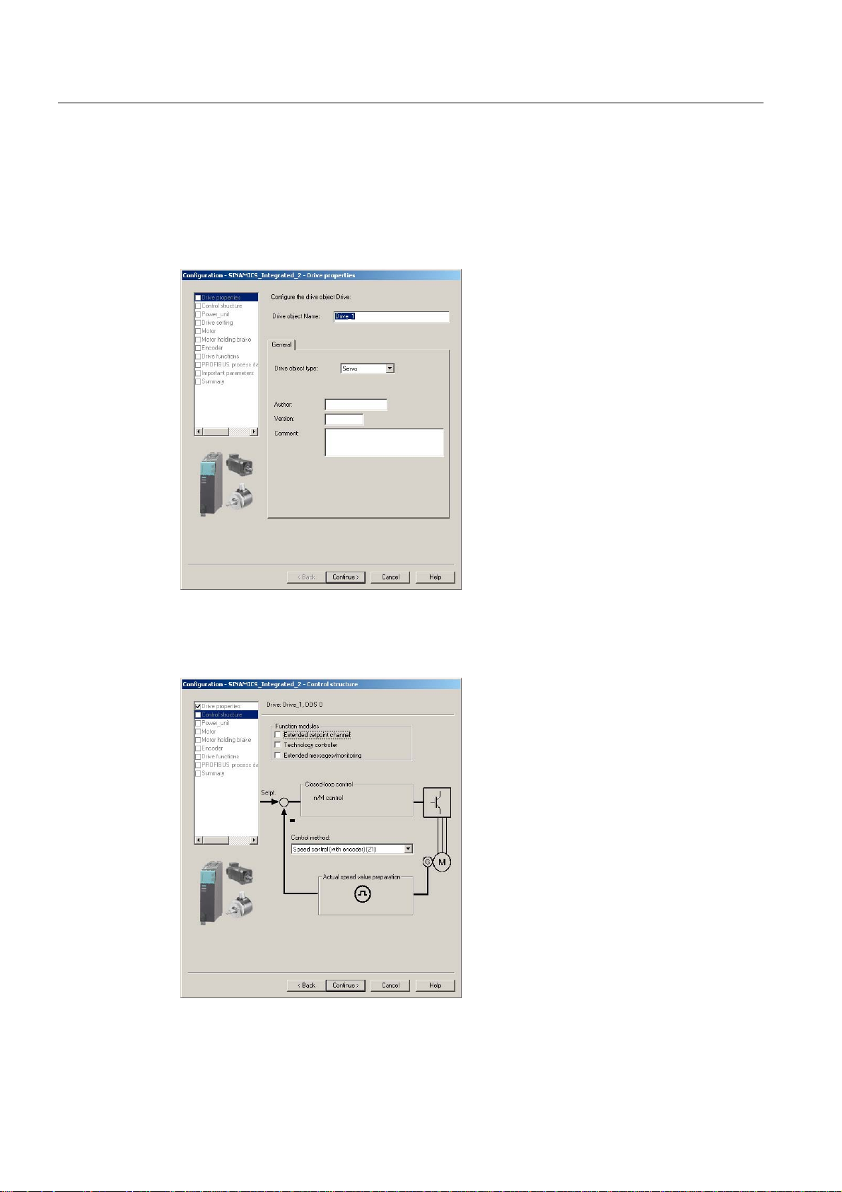
Commissioning (software)
4.2 Configuring the system in offline mode
4.2.3 Configuring the components
Procedure
1. Enter a drive name in the "Drive Properties" dialog box and select the drive type (servo or
vector).
Figure 4-1 Drive properties
2. You can select the function modules and the control mode in the "Open-loop Control
Structure" dialog box.
Figure 4-2 Control-loop structure
D410
64 Commissioning Manual, 08/2008 Edition
Page 65

Commissioning (software)
4.2 Configuring the system in offline mode
3. Select your motor module by order number from the list shown in the "Power Unit" dialog
box.
Figure 4-3 Selecting a power unit
4. Select in the "Power unit supplementary data" dialog the component added to the power
unit.
The selection of the component depends on the construction type.
– D410 DP with D410 PN: The SIMOTION D410 snapped directly onto the PM340
power module
– CUA31 or CUA32: The CUA3x snapped directly onto the PM340. The D410 is
mounted individually on a mounting plate. The D410 is connected with the CUA3x
using a DRIVE-CLiQ cable.
D410
Commissioning Manual, 08/2008 Edition
65
Page 66

Commissioning (software)
4.2 Configuring the system in offline mode
Figure 4-4 Selecting an adapter module
5. Select the motor and possibly the motor type in the next dialog box.
Figure 4-5 Selecting a motor
6. Select a motor holding brake (if installed).
D410
66 Commissioning Manual, 08/2008 Edition
Page 67

Commissioning (software)
4.2 Configuring the system in offline mode
Figure 4-6 Selecting a motor holding brake
7. Select the encoder order number in the "Encoder selection by motor order number" if
using a motor that is not equipped with a DRIVE-CLiQ interface.
Figure 4-7 Selecting the encoder order number
8. In the following dialog, select the PROFIBUS message frame.
The following message frames can be used, for example, in conjunction with SINAMICS
S120 drives:
– SIEMENS message frame 105, PSD-10/10: Dynamic life sign, torque reduction,
encoder data for an encoder, dynamic drive control (DSC)
D410
Commissioning Manual, 08/2008 Edition
67
Page 68

Commissioning (software)
4.2 Configuring the system in offline mode
– SIEMENS message frame 106, PSD-11/15: Dynamic life sign, torque reduction,
encoder data for two encoders, dynamic drive control (DSC)
Advantages of DSC (compared to a position controller in the control unit):
● Higher Kv (position controller gain) possible
● Larger bandwidth and consequently higher dynamic response
● Shorter response times for disturbance characteristic
The DSC dynamic drive control can be used for the SIEMENS message frame 105, PSD10/10 and SIEMENS message frame 106, PSD-11/15. The DSC is activated by default for
the configuration of the axis using the Drive Wizard.
Detailed information for the various message frame types is contained in the Motion Control,
Electrical/Hydraulic Axis Technology Object, External Encoder function manual.
Figure 4-8 Selecting the PROFIBUS message frame
A "Summary" dialog box opens with a listing of all settings after you completed all settings in
the Drive Wizard. You can now choose to activate your settings by clicking "Finish", or to
return to the component configuration for further editing.
D410
68 Commissioning Manual, 08/2008 Edition
Page 69

Commissioning (software)
4.2 Configuring the system in offline mode
Figure 4-9 Finishing the drive
The configured drive is displayed in the Project Navigator. An overview of your configured
SINAMICS components is available in the "SINAMICS_Integrated" > "Topology" dialog.
D410
Commissioning Manual, 08/2008 Edition
69
Page 70
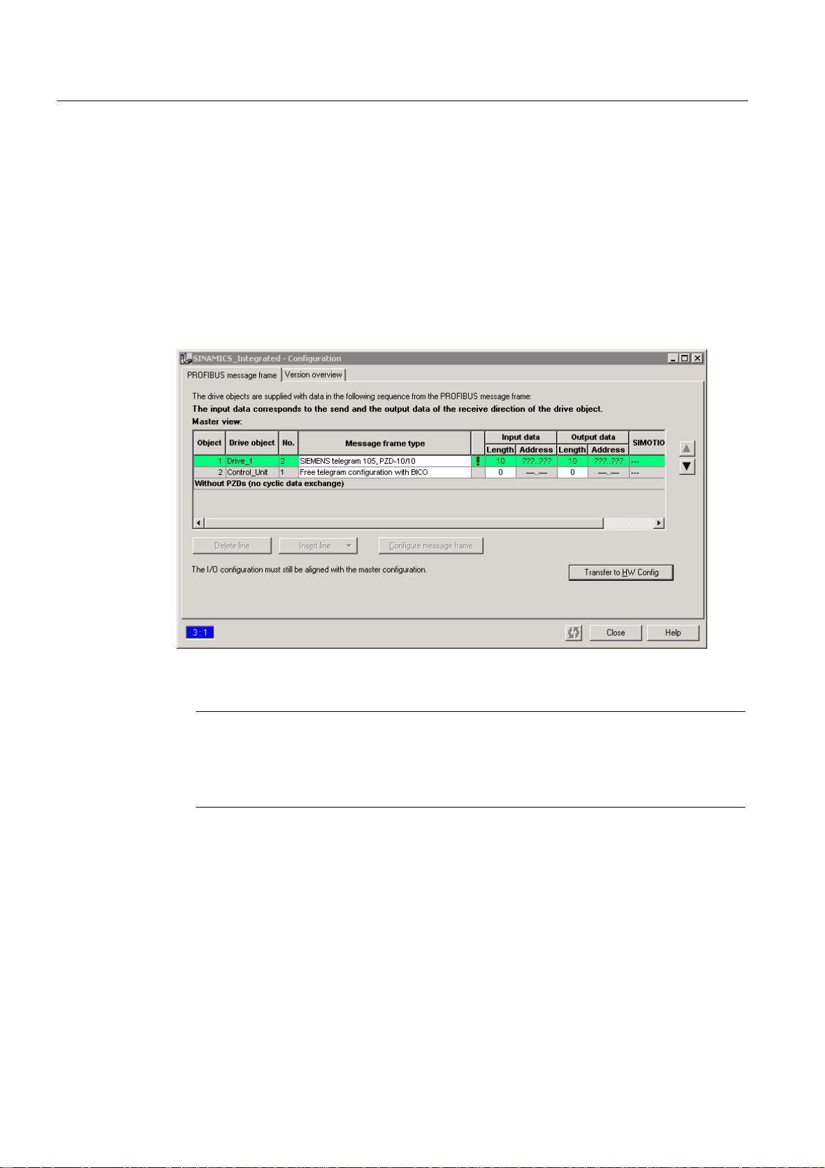
Commissioning (software)
4.2 Configuring the system in offline mode
4.2.4 Aligning HW Config
After having completed the configuration of all SINAMICS components, align the data with
HW Config.
Proceed as follows:
1. Open the "Configuration" entry in the "SINAMICS_Integrated" tree in the Project
Navigator. The "SINAMICS_Integrated - Configuration" dialog box opens with a list of
configured drive objects.
The question marks in the I/O address fields indicate that you have not yet defined the
I/O addresses of the drive objects.
Figure 4-10 Configuration prior to HW Config alignment
Note
Drive objects without address must be positioned at the end of the list, for otherwise it is
not possible to align HW Config ("Align with HW Config"). To move the order of a drive
object without address, select the associated drive object and move it downwards using
the arrow key.
2. Click "Align with HW Config" in order to assign addresses to the configured components.
The addresses are written to HW Config.
D410
70 Commissioning Manual, 08/2008 Edition
Page 71

Commissioning (software)
4.2 Configuring the system in offline mode
Figure 4-11 Configuration after HW Config alignment
Note
Repeat the HW Config alignment if the message frames for SINAMICS Integrated were
changed. The addresses are not updated automatically.
4.2.5 Downloading the project to SIMOTION D410
Procedure for downloading a project into the target system
1. Save and compile the project.
2. Go online to SIMOTION D410.
3. Select the "Download project to target system" command to download the project to
SIMOTION D410. The connection to SINAMICS Integrated is activated automatically.
The drive has been assigned parameters and commissioned. You can now test the drive
using the drive control panel.
Note
Online access to SINAMICS Integrated is not possible if HW Config is not loaded at the time
you initially connect to the target system.
Download the data to HW Config in order to enable online access to SINAMICS Integrated.
D410
Commissioning Manual, 08/2008 Edition
71
Page 72

Commissioning (software)
4.2 Configuring the system in offline mode
Procedure for downloading a created project to the CF card
You can use a card reader to also write the entire project to the CF Card in offline mode. In
the SIMOTION SCOUT, you can call the "Download to the file system" function in the
context menu of the SIMOTION device.
1. Save and compile the project.
2. Switch off the SIMOTION D410.
3. Remove the CF card and insert it in a card adapter. The card adapter must be connected
with a programming device / PC.
4. Select in the SCOUT project the SIMOTION D410 device that you want to download to
the CF card.
5. Click "Download to the file system" in the context menu. A dialog box opens.
6. Click the "Select target" button in the "Download to the file system" dialog box.
7. Select the target drive.
8. Confirm your entries with "OK". The data will be written to the CF card.
9. Remove the CF card and insert it in the D410 slot.
Note
The initial startup from the CompactFlash Card you configured in offline mode takes
longer.
The firmware of the SINAMICS component is updated automatically if any higher
firmware version is found on the CF card. Observe any messages and alarms in the
details window of the SIMOTION SCOUT after a firmware update. After having updated
the firmware of a SINAMICS component, go offline and then switch off the power supply
of the upgraded component (Power Off/On).
10. Switch on the D410. The D410 starts with the downloaded project.
D410
72 Commissioning Manual, 08/2008 Edition
Page 73

Commissioning (software)
4.3 Configuring the system in online mode
4.3 Configuring the system in online mode
4.3.1 Overview
Introduction
You can configure the plant in online mode after having completed its wiring. You can upload
the data of SINAMICS components connected via DRIVE-CLiQ to your programming device
/ PC using the "Automatic configuration" function. However, this functionality is only available
within the initial commissioning phase.
Note
Components without DRIVE-CLiQ connection must be edited in offline mode. You may need
to edit DRIVE-CLiQ components which were detected in the course of automatic
configuration (for example, adding encoder data if using SMC modules).
Prerequisites for online configuration
● You created a project in SIMOTION SCOUT and added a SIMOTION D410 to the project.
● You configured the communication between the the programming device / PC and
SIMOTION D410.
Procedure
Steps involved in offline configuring:
● Establishing the online connection
● Starting automatic configuration
● Configuring SINAMICS components
● Aligning HW Config
● Downloading the project to SIMOTION D410
D410
Commissioning Manual, 08/2008 Edition
73
Page 74

Commissioning (software)
4.3 Configuring the system in online mode
4.3.2 Establishing the online connection
The procedure for an initial commissioning follows.
To perform an online configuration, you must establish an online connection to the
SIMOTION D410. In this case, no connection can yet be established to SINAMICS
Integrated. An appropriate message is output. Once the hardware configuration has been
loaded into the target device, an online connection to the SINAMICS Integrated is
established automatically. Proceed as follows:
1. Save and compile the project.
2. Establish an online connection.
3. Select the SIMOTION D410 device in the Project Navigator.
4. Use the "Download to the target device" function to download the SIMOTION D410
You can now run the automatic configuration at SINAMICS Integrated. For details, see
Section
Additional references
Further information about establishing an online connection to the programming device / PC
is contained in the following documentation:
●
●
● In FAQ on the
Note
Ensure that you use the "Download to the target device" function rather than "Download
to the target system". An automatic commissioning is no longer possible after "Download
to the target system". If "Download to the target system" has been used, "Restore factory
settings" must be performed on the drive element in order to start an automatic
commissioning afterwards.
device into the target device. The connection to SINAMICS Integrated is activated
automatically.
Starting automatic configuration (Page 75).
SIMOTION SCOUT
SIMOTION SCOUT
Configuration Manual
Online Help
"Utilities & Applications"
CD
D410
74 Commissioning Manual, 08/2008 Edition
Page 75
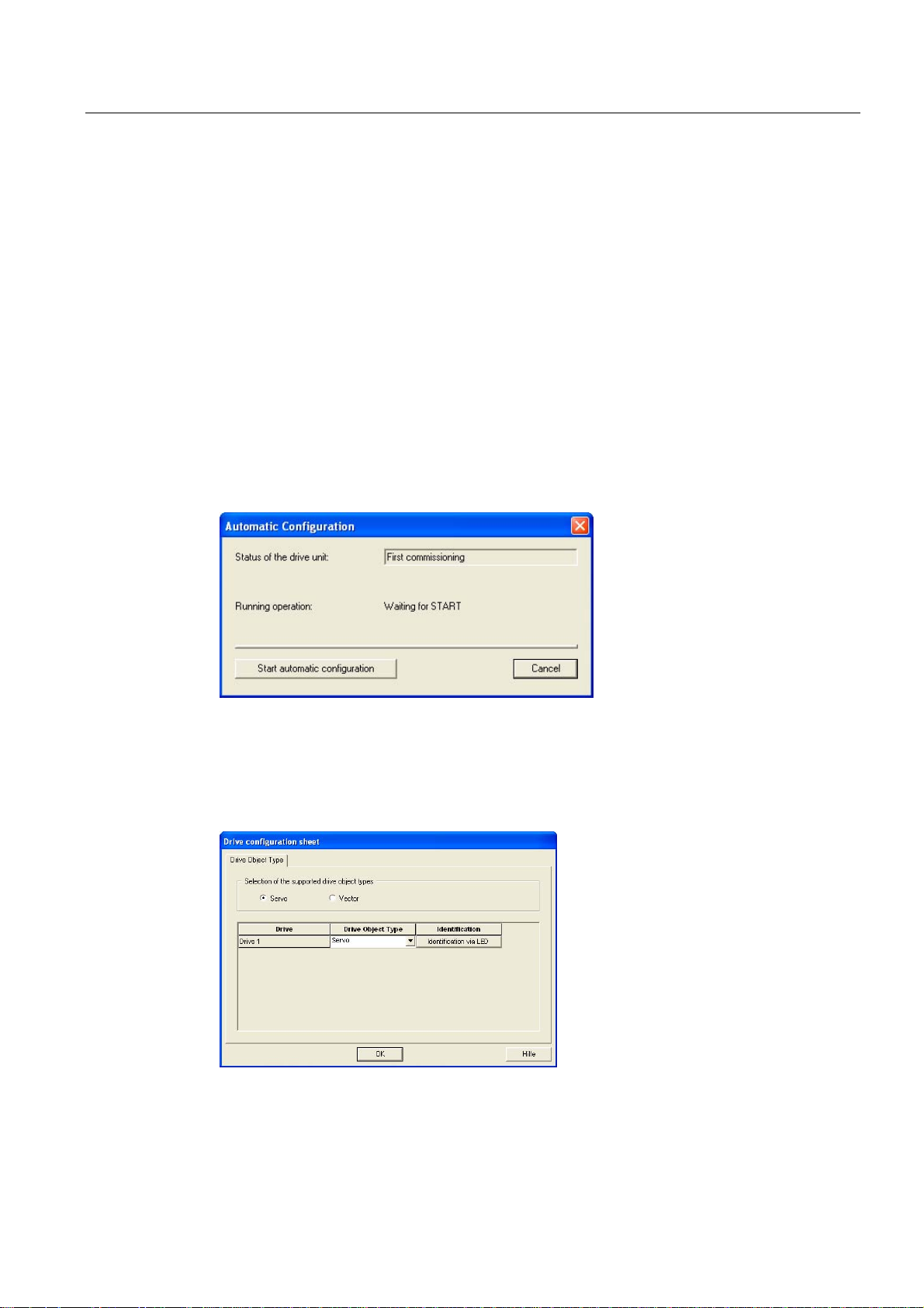
Commissioning (software)
4.3 Configuring the system in online mode
4.3.3 Starting automatic configuration
Prerequisites
● You activated the online connection to SINAMICS Integrated.
● You have not yet configured any drive objects.
● The default settings of SINAMICS Integrated were activated.
Right-click SINAMICS Integrated" and select the "Target device" > "Restore defaults"
command from the shortcut menu in SIMOTION SCOUT in order to restore the factory
settings.
Procedure
1. Open the "Automatic Configuration" dialog box by selecting the "SINAMICS_Integrated >
Automatic configuration" command in the Project Navigator.
Figure 4-12 Starting automatic configuration
2. Click "Start automatic configuration".
The "Drive Object Type" dialog box opens.
Figure 4-13 Selecting the drive object type
D410
Commissioning Manual, 08/2008 Edition
75
Page 76

Commissioning (software)
4.3 Configuring the system in online mode
3. Select either a servo or a vector drive object.
4. Click "Close" to complete automatic configuration.
The configuration data is uploaded (Upload to PG) automatically as soon as automatic
commissioning is completed.
Note
If the firmware of the SINAMICS components differs from the firmware on the CF card,
the firmware of the SINAMICS components will be upgraded automatically.
5. Click "Close" to exit automatic configuration.
Result
Figure 4-14 Automatic configuration completed
6. Perform the "Copy RAM to ROM ..." function on the D410 and on SINAMICS Integrated.
This saves the project on the CF card and does not need to be reloaded after a switchon/switch-off.
Note
After having updated the firmware of a SINAMICS component, go offline and then switch
off the power supply of the upgraded component (Power Off/On).
The DRIVE-CLiQ components transferred to the user project by means of the automatic
configuration are displayed in the Project Navigator.
D410
76 Commissioning Manual, 08/2008 Edition
Page 77

Commissioning (software)
4.3 Configuring the system in online mode
Figure 4-15 Project Navigator with the downloaded DRIVE-CLiQ components
You must then define the axis message frame and possibly edit the SINAMICS components
(e.g. components without DRIVE-CLiQ interface and an encoder connected to the onboard
encoder interface).
See also
Editing SINAMICS components (Page 77)
4.3.4 Editing SINAMICS components
Prerequisites
● You have uploaded all connected DRIVE-CLiQ components to the user project.
● You shut down the connection to the target system (offline mode).
D410
Commissioning Manual, 08/2008 Edition
77
Page 78

Commissioning (software)
4.3 Configuring the system in online mode
Procedure
Now go ahead and adapt your components to suit the application.
Run the wizards for all DRIVE-CLiQ components to be customized and configure the motor,
encoder, and process data message frames (PROFIBUS message frame type).
This procedure corresponds with the description in chapter "Configuring the system in offline
mode".
Note
If only the message frame type needs to be selected for the edit, you can also set this in the
"Configuration" screen form of the drive element. A HW Config match is then required.
Configuring the system in offline mode (Page 62)
4.3.5 Aligning HW Config
See also
Aligning HW Config (Page 70)
4.3.6 Download the project to SIMOTION D410
After having aligned HW Config, download the configuration to SINAMICS Integrated.
1. Save and compile the project.
2. Go online to SIMOTION D410.
3. Select the "Download project to target system" command to download the project to
SIMOTION D410. The connection to SINAMICS Integrated is activated automatically.
Drive programming and commissioning is completed. You can now test the drive using the
drive control panel.
D410
78 Commissioning Manual, 08/2008 Edition
Page 79
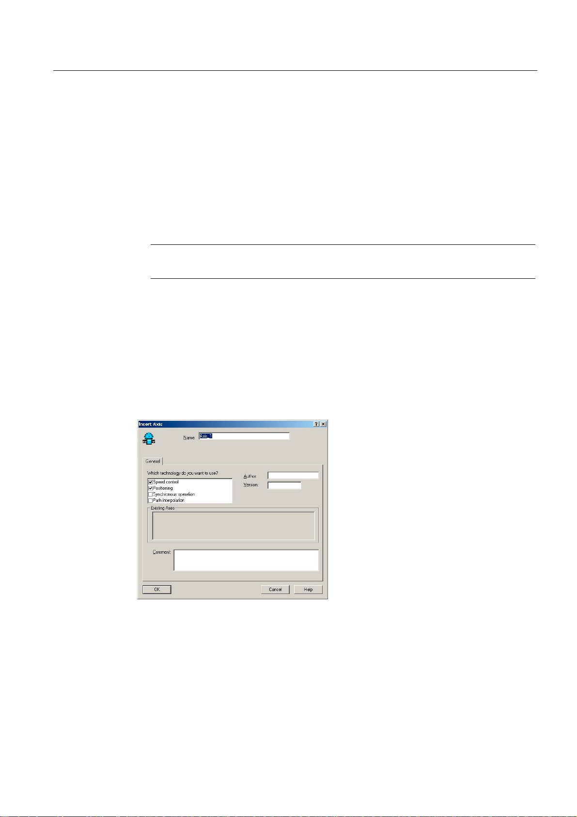
Commissioning (software)
4.4 Creating an axis
4.4 Creating an axis
Overview
The SIMOTION SCOUT Engineering System can be used to insert axes in your project.
1. Start a session of the Axis Wizard in order to configure the axes and interconnect these
with the SINAMICS Integrated drive.
2. Insert your user programs into the project.
Note
Note that only one real axis can be used on a SIMOTION D410.
Creating an axis using the Axis Wizard
Axes are integrated as technology objects (TOs) in SIMOTION. Create the axis with
corresponding settings under the SIMOTION D410 and then interconnect it with
SINAMICS Integrated.
How to insert an axis:
1. Double-click the "Axis > Insert Axis" entry in the Project Navigator.
This opens the Axis Wizard.
3. Compile the project and download it to SIMOTION D410.
Figure 4-16 Inserting an axis
2. Name the axis TO in the "Insert Axis" dialog box, select the technology and save and
confirm your entries with "OK".
3. Continue the Axis Configuration Wizard and enter your system settings until the "Drive
Assignment" dialog box opens.
4. Click "Align SINAMICS devices..." to open the "Device Alignment" dialog box.
D410
Commissioning Manual, 08/2008 Edition
79
Page 80

Commissioning (software)
4.4 Creating an axis
5. Select the drive to be aligned (SINAMICS Integrated) in this dialog box and then click
"Align".
The addresses are assigned to the configured components and entered in HW Config.
Note
This device alignment is only necessary if not already done in the course of drive
commissioning. This shows that no interconnectable drive of the SINAMICS Integrated
type is displayed.
Figure 4-17 Assigning a drive
6. Select a drive unit in the "Drive Assignment" dialog box. Normally only a SINAMICS
Integrated drive will be offered. Exception: A D410 has been configured, for example,
with a hydraulic axis. You have already defined the message frame type in the previous
steps and so only need to accept it. To do this, click the "Accept data from the drive"
button to transfer the SINAMICS Integrated values in the axis wizards.
7. Select the encoder from the "Encoder Assignment" dialog box and then adapt its
properties. Click the "Accept data from the drive" button to transfer the SINAMICS
Integrated values in the axis wizards.
Note
For motors with DRIVE-CLiQ interface, a "Accept data from the drive" automatically
transfers the determined drive and encoder data (e.g. encoder type). This requires that
the data has already been fetched from the attached devices. Namely, an offline
configuration has already been used to establish an online connection or an online
configuration has been performed.
8. Complete the Axis Wizard session.
The configured axis is displayed in the Project Navigator. After having downloaded it to the
target system, you can test the axis using the axis or drive control panel.
D410
80 Commissioning Manual, 08/2008 Edition
Page 81

Commissioning (software)
4.5 Integrating additional encoders (optional)
4.5 Integrating additional encoders (optional)
4.5.1 General information
SIMOTION D410 provides the option of integrating and configuring further encoders in
addition to the motor encoder.
The following encoders are supported for operation with SIMOTION D410:
● Encoders with DRIVE-CLiQ interface
● Encoders connected to SIMOTION D410 using the onboard encoder interface (X23)
● Encoders connected to SIMOTION D410 using an SMx module
● Encoders connected using PROFIBUS or PROFINET
Prerequisite
SIMOTION D410 features a DRIVE-CLiQ X100 interface for connecting an encoder. An
additional encoder can be connected, for example, using the on-board encoder interface
(X23).
Configuring two encoders
The second encoder can be used at SIMOTION D410, for example, as:
● Machine encoder (second encoder)
● External encoder.
The external encoder can be used, for example, to measure an actual position value directly
on a geared motor. If operating with a second encoder as machine encoder you can work
with encoder changeover.
Configuring tasks
Encoders connected using PROFIBUS or PROFINET are configured only for SIMOTION.
Encoders connected using SMx, DRIVE-CLiQ or the onboard encoder interface, must be
configured for the drive (SINAMICS Integrated) and SIMOTION.
Configure this additional encoder on drive side (SINAMICS Integrated) and in SIMOTION:
1. Configure the encoder interface on the drive side (second encoder)
2. Configuring a second encoder for a TO axis in SIMOTION
3. Configuring an external encoder in SIMOTION
These steps in configuring are described in the next section.
D410
Commissioning Manual, 08/2008 Edition
81
Page 82

Commissioning (software)
4.5 Integrating additional encoders (optional)
4.5.2 Configure the encoder interface on the drive side
Prerequisite
You configured the drive with an encoder in the Drive Wizard.
Procedure
1. Open the "Configuration" entry of your drive by selecting the "SINAMICS_Integrated" >
Drives" command in the Project Navigator. The "Configuration" dialog box opens.
2. Click "Configure DDS..." to open the Drive Wizard.
3. Step the Drive Wizard forward until the "SINAMICS_Integrated - Encoders" dialog box
opens.
4. Select the "Encoder 2" option in this dialog. The dialog box displays a list of available
encoders.
5. Select for "encoder evaluation":
– SMx for the encoder connection using DRIVE-CLiQ / SMx
– D410 DP (or D410 PN) for the encoder connection using the onboard encoder
interface
Figure 4-18 Selecting the internal encoder interface
6. Select the connected encoder and confirm with "Continue".
D410
82 Commissioning Manual, 08/2008 Edition
Page 83

Commissioning (software)
4.5 Integrating additional encoders (optional)
7. In the "Configuration - SINAMICS Integrated - PROFIBUS (drive) Process Data
Exchange" dialog box, select a message frame that supports the transmission of two
encoder values (e.g. SIEMENS message frame 106, PSD-11/15).
8. Click "Continue" to complete the Drive Wizard.
9. Click "Transfer to HW Config" in the "SINAMICS_Integrated - Configuration" dialog box in
order to align HW Config.
The drive is configured for operation with two encoders.
4.5.3 Configuring a second encoder for a TO axis in SIMOTION
Requirements
● You have configured a drive with two encoders as specified in Section Configure the
encoder interface on the drive side (Page
● The set message frame supports the transmission of two encoder values.
● The configuration of the PROFIBUS message frames has been matched with HW Config.
82).
Procedure
1. In the Project Navigator, open the Axis Wizard of the axis.
2. In the "Drive Assignment" dialog box, select the same message that you have already
used to configure the second encoder on the SINAMICS Integrated or in the "SINAMICS
Integrated > Configuration" screen form (e.g. SIEMENS message frame 106, PSD11/15).
3. Complete the Axis Wizard session.
You have configured a second encoder for an axis TO in SIMOTION. The set message
frame type now allows you to use the value of a second encoder.
D410
Commissioning Manual, 08/2008 Edition
83
Page 84

Commissioning (software)
4.5 Integrating additional encoders (optional)
4.5.4 Configuring external encoders in SIMOTION
Prerequisite
Encoder using PROFIBUS/PROFINET
You have used HW Config to configure an encoder on the PROFIBUS or PROFINET. Two
different possibilities are available for the encoder connection:
● Encoder interconnection using a PROFIdrive message frame (encoder with message
frame type 81)
● Encoder interface as a direct value in the I/O area
Detailed information is contained in the "SIMOTION TO Axis, Electric/Hydraulic, External
Encoder" Function Manual
Encoder on the drive
You configured a drive with two encoders, and then an electric axis with the PROFIBUS
message frame to be used.
Procedure
1. Open the wizard for configuring an external encoder by selecting the "External Encoders"
2. Assign a name in the "Inserting an external encoder" screen form and, if required, enter
3. Execute the wizard for the encoder configuration and enter the appropriate values in the
The external encoder is now configured and uses the second value which is transferred by
means of the selected PROFIBUS message frame.
Additional references
Detailed information for the external encoder is contained in the
Axis, Electric/Hydraulic, External Encoder
> "Insert external encoder" folder in the Project Navigator.
the author and version.
screen forms.
SIMOTION SCOUT TO
Function Manual.
D410
84 Commissioning Manual, 08/2008 Edition
Page 85

Commissioning (software)
4.6 Using drive-related I/Os by SIMOTION
4.6 Using drive-related I/Os by SIMOTION
4.6.1 Onboard I/Os and terminal modules configuration overview
Using SINAMICS I/Os by SIMOTION
Digital inputs/outputs (I/Os) assigned to SINAMICS can be used completely or partially by
SIMOTION. Examples here are the use of terminal modules (TMs) or onboard I/Os of the
D410. To allow the I/Os to be used by SIMOTION, the input and output data must be
transferred using message frames. This message frame configuration is used to represent
the I/Os in the logical address space of SIMOTION and so can be used by a SIMOTION
application. The BICO interconnections on the drive specify which I/Os are represented on
the message frame.
These BICO interconnections can be:
● Freely defined (free message frame configuration; message frame extension).
● Permanently defined (standard message frames, e.g. message frame 39x; axis message
frames). . .)
● Configuration dependent (TM15/TM17 High Feature).
The access to the message frame for SIMOTION D410 is made using I/O variables or
input/output addresses. Depending how the I/Os are to be used, various configuration
possibilities are appropriate:
Table 4-1 Use of I/Os by SIMOTION, overview
Configuration Description Applications Supported I/Os
(drive objects)
Use of message frame
39x
Free message frame
configuration with
P915/P916
(TM15/TM17 High
Feature special case)
Configuring free message
frames by means of BICO
Possible only for D410 onboard
I/Os. The 39x message frames can
be used by SIMOTION to access
the onboard I/Os of the D410.
For the TM15/TM17 High Feature,
when the module is created, an
automatic interconnection to a
"free message frame with
P915/P916" is made. This means
TMs are available exclusively for
SIMOTION.
Dedicated message frame for the
data transmission are assigned to
the associated drive objects. The
"free message frame configuration
using BICO", message frame 999,
is used for the data transmission
here.
Configuration when, for example,
all SIMOTION I/Os are to be
used. Use of:
• High-speed outputs of output
cams
• Global measuring inputs
Use of TM15 and TM17 High
Feature for:
• High-speed DI/DO
• Outputs of output cam
• Probe inputs
Preferred solution when I/Os are
to be divided between
SIMOTION and SINAMICS and
a module view is preferred. The
message frame, for example, is
created on a drive object (for
example, on a TM or a control
unit).
• Onboard I/Os on
the D410
• Onboard I/Os on
CU310 (no highspeed outputs for
output cams)
• TM15
• TM17 High
Feature
• Onboard I/Os on
the D410
• Onboard I/Os on
CU310
• TM15 DI/DO
• TM31
• TM41
D410
Commissioning Manual, 08/2008 Edition
85
Page 86

Commissioning (software)
4.6 Using drive-related I/Os by SIMOTION
Configuration Description Applications Supported I/Os
(drive objects)
Expanding a message
frame
For the data transmission of the I/O
data, existing message frames are
extended with the process status
data (PSD). These additional PSDs
must then be interconnected using
BICO.
Preferred solution when I/Os are
to be divided between
SIMOTION and SINAMICS and,
for example, an axis view is
preferred. (Drive-related I/Os are
appended to each axis message
frame.)
• Onboard I/Os on
the D410
• Onboard I/Os on
CU310
• TM15 DI/DO
• TM31
• TM41
Note
The module hardware for TM15 and TM15 DI/DO is identical. The differentiation is made
only with the addition of the component in the Project Navigator of the SIMOTION SCOUT
using "Inserting input/output component".
Further information about the TM15 and TM17 High Feature is contained in the
TM17 High Feature
Commissioning Manual.
TM15 and
Note
The "free message frame configuration using BICO" and the "message frame extension"
allow you to use inputs/outputs channel-granular by SIMOTION or SINAMICS.
For message frame 39x, however, all onboard terminals are interconnected automatically to
message frame 39x using BICO interconnections and so available only for SIMOTION. The
following is true:
• All onboard I/Os configured as digital output for the drive are only available for
SIMOTION, i.e. they can no longer be used by SINAMICS.
• Digital inputs can be used by SIMOTION and SINAMICS.
D410
86 Commissioning Manual, 08/2008 Edition
Page 87

Commissioning (software)
4.6 Using drive-related I/Os by SIMOTION
4.6.2 Use of message frame 39x
The following section describes the configuration of the onboard I/Os of a SIMOTION D410.
The configuration of the onboard I/Os of a CU310 connected to a SIMOTION controller is
performed similarly. With the exception of the "high-speed output cams / DOs", the same
functionality is available for a CU310 as the D410.
Functionality of the 390, 391 and 392 message frames
The onboard I/Os of the D410 assigned to SINAMICS can be used by SIMOTION with the
39x message frames. This functionality is available as of SIMOTION V4.1, SP1. If a
message frame 39x is set, however, all the onboard I/Os are interconnected automatically to
this message frame 39x using BICO interconnections and so available for SIMOTION. All
onboard I/Os of a control unit parameterized as digital output, e.g. D410s are available only
for SIMOTION. Digital inputs can be used by both SIMOTION and SINAMICS.
In addition to the use of the onboard I/Os, the 39x message frame permits the use of:
● High-speed outputs for output cams and high-speed digital outputs (DO)
● "Global" measuring inputs
● The control and status word of the control unit (CU_STW, CU_ZSW)
Depending on the selected 39x message frame, various functionalities can be used with
SIMOTION D.
Table 4-2 Functionality of the 390, 391 and 392 message frames, overview
Concise Functionality available on the DI/DO of the D410
390
391
392
Because the same terminals are used, the maximum "high-speed output cams / DOs"
quantity framework reduces by the number of used inputs for measuring inputs.
The configuration of local measuring inputs does not require the configuration of message
frame 39x.
Message frame 39x configuration
The following requirements must be satisfied:
• CU_STW, CU_ZSW
• I/O access to the DIs and DOs
• Maximum of four high-speed output cams / DOs
• CU_STW, CU_ZSW
• I/O access to the DIs and DOs
• Maximum of four high-speed output cams / DOs
• Maximum of two inputs for measuring inputs (global measuring inputs)
• CU_STW, CU_ZSW
• I/O access to the DIs and DOs
• Maximum of four high-speed output cams / DOs
• Maximum of three inputs for measuring inputs (global measuring inputs)
● A SCOUT project has been created
● The D410 has been created
● A SINAMICS Integrated drive has been configured
D410
Commissioning Manual, 08/2008 Edition
87
Page 88

Commissioning (software)
4.6 Using drive-related I/Os by SIMOTION
Proceed as follows:
1. In the Project Navigator, double-click the "Configuration" entry under "SINAMICS
Integrated". In the workarea, the "PROFIBUS message frame" tab is displayed in the
"SINAMICS Integrated - Configuration" dialog box.
2. Select the message frame type (SIEMENS message frame 390, 391 or 392) for the
control unit.
3. Click the "Transfer to HW Config" button to transfer the message frame data to hardware
configuration.
A message frame 39x is configured for the D410 control unit. The address area of the
message frame is displayed in "SINAMICS_Integrated – Configuration" dialog. The 39x
message frame configuration automatically makes the BICO interconnections for the DI and
DI/DO which are then available for SIMOTION.
Figure 4-19 Message frame 39x configuration
D410
88 Commissioning Manual, 08/2008 Edition
Page 89

Commissioning (software)
4.6 Using drive-related I/Os by SIMOTION
Use of the onboard I/O by SIMOTION
For DI/DO channels, the terminal status of the output can be fetched back using the input
(DI).
The 390 message frame transfers in PSD1 the control and status word of the control unit
and in PSD2 the status of the onboard inputs/outputs.
For the 391 and 392 message frames, additional control and status information for the global
measuring inputs is transferred. The content of these PSD3 to PSD15 is used exclusively by
the measuring input technology object.
Table 4-3 D410 assignment of the addresses: Control/status word and onboard I/Os
PSD Logical hardware address and bit number: Input Output
PSD1 Start address message frame 39x + 0 CU_ZSW CU_STW
PSD2
PSD3 Start address message frame 39x + 4 Used internal for global measuring
PSD4-7 Start address message frame 39x + +6 Used internal for global measuring
PSD8-15 Start address message frame 39x + +10 Used internal for global measuring
Start address message frame 39x + 2, bit 0
Start address message frame 39x + 2, bit 1
Start address message frame 39x + 2, bit 2
Start address message frame 39x + 2, bit 3
Start address message frame 39x + 3, bit 0
Start address message frame 39x + 3, bit 1
Start address message frame 39x + 3, bit 2
Start address message frame 39x + 3, bit 3
DI 0
DI 1
DI 2
DI 3
DI 8
DI 9
DI 10
DI 11
inputs
(only for message frame 391, 392)
inputs 1 to 2
(only for message frame 391, 392)
input 3
(only for message frame 392)
–
–
–
–
DO 8
DO 9
DO 10
DO 11
–
–
–
To allow access by the I/Os to the individual PSDs, I/O variables must be created in
SIMOTION. For this purpose, the input/output addresses displayed in the "PROFIBUS
message frame" tab in the "SINAMICS Integrated - Configuration" dialog box are required.
The following figure shows an example of I/Os created in SCOUT: In this example, the start
address of the 390 message frame for the input and output data is each 276.
Figure 4-20 Example: Access to message frame 390 using I/O variables.
D410
Commissioning Manual, 08/2008 Edition
89
Page 90
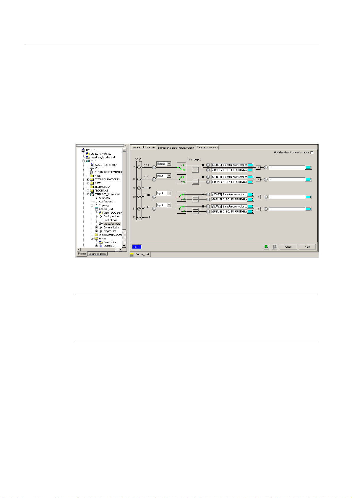
Commissioning (software)
4.6 Using drive-related I/Os by SIMOTION
Configuring DI/DO as input or output
When a DI/DO is to be used as digital input or digital output, interconnection screen forms
can be used for configuring.
Proceed as follows:
1. Double-click the "Inputs/outputs" entry below the SINAMICS_Integrated > Control Unit in
the Project Navigator.
2. Click the "Bidirectional digital inputs/outputs" tab.
3. In this tab, configure the required inputs or outputs.
Figure 4-21 Configuring DI/DOs as input or output
The configuration can also be set channel-granular on the p728 parameter using the expert
list of the control unit.
Note
When the 39x message frames are used, a HW Config must always be performed after
changes have been made to onboard I/O-relevant parameters. "Download to the target
system" must then be used to download the changed configuration data into the target
device. The matching is always made only for the associated selected control unit and not
project-global.
D410
90 Commissioning Manual, 08/2008 Edition
Page 91

Commissioning (software)
4.6 Using drive-related I/Os by SIMOTION
4.6.3 Free message frame configuring with P915/P916 (only TM15/TM17 High Feature)
The TM15 and TM17 High Feature terminal modules are connected to the control unit using
the DRIVE-CLiQ interface. This assigns the terminal modules to the SINAMICS. When a
TM15 or TM17 High Feature is added to SIMOTION SCOUT, an automatic interconnection
to a "free message frame with P915/P916" is made. Other interconnection possibilities exist.
Not for TM15 (but not TM15 DI/DO) and TM17 High Feature.
The structure and the length of the message frame depends on the configured properties of
the inputs and outputs. The I/O channels can be parameterized as digital input, digital
output, input for measuring input or output for output cam.
The automatic interconnection of the message frame means the functionality of the modules
can only be used by SIMOTION and is controlled from the SIMOTION user program using
input/output addresses or I/O variables. A drive-side configuring using BICO / DCC
SINAMICS is not possible.
Additional references
Additional information about this topic is available in the following documents:
● To configure TM15 and TM17 High Feature, refer to the
Commissioning Manual.
● To configure output cams and measuring inputs, refer to the
Output Cams and Measuring Inputs
● For the I/O processing with TM15 and TM17 High Feature (timing, classification in the
task system), refer to the
SIMOTION SCOUT Basic Functions
Function Manual.
TM15 and TM17 High Feature
SIMOTION Motion Control
Function Manual.
D410
Commissioning Manual, 08/2008 Edition
91
Page 92

Commissioning (software)
4.6 Using drive-related I/Os by SIMOTION
4.6.4 Configuring free message frames by means of BICO
Overview
For the "free message frame configuring using BICO", dedicated message frames for the
data transmission are assigned to the associated drive objects (e.g. terminal modules).
Message frame type: Free message frame configuring using BICO (only slaves)
To allow SIMOTION to access the SINAMICS drive signals, e.g. I/Os, they must be
interconnected to the SINAMICS using BICO to the message frame. The "free message
frame configuring using" is a preferred solution when I/Os are to be divided channel-granular
between SIMOTION and SINAMICS and a module view is preferred.
Table 4-4 Drive object: Maximum number of PSDs
Drive object
TM15 DI/DO 5 5
TM31 5 5
TM41 19 16
Control Unit (CU) 15 5
Maximum number of PSDs for the configuring of the PROFIBUS
message frames
Input data
(from the SIMOTION D
viewpoint)
Free message frame configuring using the TM31 as example
The example describes the interconnection of a signal to the TM31 connected to a
SIMOTION D410.
Steps in configuring user-specific message frames using BICO:
● Configure a user-specific message frame
● Interconnect the message frame for TM31
● Create I/O variables in SIMOTION SCOUT
Prerequisite
You have already created a project and configured a drive.
Output data
(from the SIMOTION D
viewpoint)
D410
92 Commissioning Manual, 08/2008 Edition
Page 93

Commissioning (software)
4.6 Using drive-related I/Os by SIMOTION
Configuring user-specific message frames
1. Double-click the "Insert I/O component" entry in "SINAMICS_Integrated" in the Project
Navigator and then select terminal module "TM31" from the "Operating type" field of the
dialog box shown.
2. Enter a name for the module to be inserted and confirm your entry with OK.
3. Double-click the "Configuration" entry at "SINAMICS Integrated" in the Project Navigator
to open the "PROFIBUS Message Frame" screen form.
"Free message frame configuration with BICO" (message frame 999) is set for the
inserted TM31. Insert the number of PSDs (Process Status Data) for I/O data. Observe
the maximum possible number of PSDs for the various drive objects (see previous table).
An TM31, for example, supports five PSDs in both the send and the receive direction.
4. Enter the value 5 in the "Length" column in the "Input data" or "Output data" fields.
Figure 4-22 Inserting a specific number of PSDs for the I/O data.
5. Click "Transfer to HW Config" in order to transfer the data to HW Config and to read the
address space of the I/O data.
D410
Commissioning Manual, 08/2008 Edition
93
Page 94
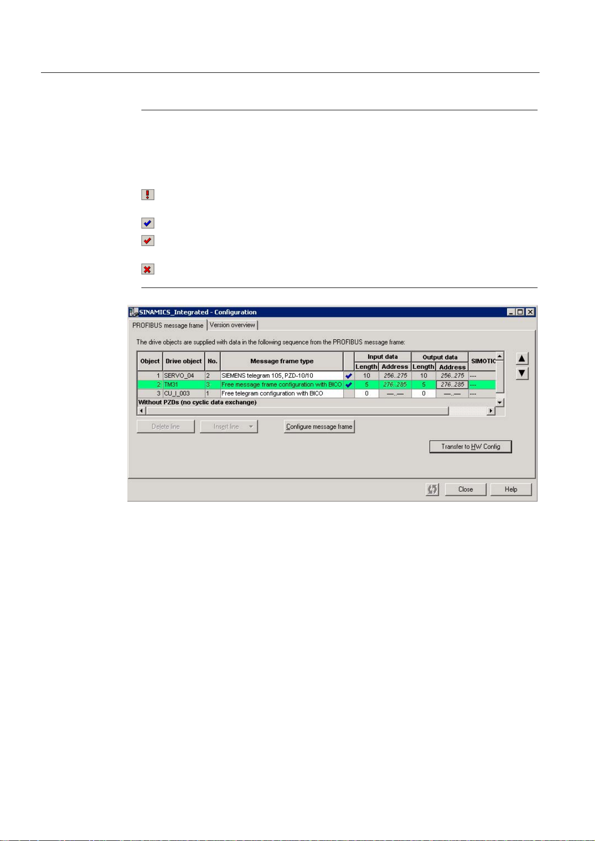
Commissioning (software)
4.6 Using drive-related I/Os by SIMOTION
Note
Before the matching, all drive objects without input/output addresses ("---..---") must be
moved behind the objects with valid input/output addresses or those still to be matched
("???..???").
The icons in the status column show the following information:
The message frame is configured differently in HW Config. You must match with HW
Config.
You use a predefined standard message frame or free BICO interconnection.
You use a changed standard message frame that you have extended with additional
data.
You use a message frame for which one of the two message frame lengths is too
long. The drive object cannot process this entry.
Figure 4-23 Reading the I/O address space
You can now transfer data from TM31 to SIMOTION (PROFIBUS send direction) or receive
data from there (PROFIBUS receive direction).
D410
94 Commissioning Manual, 08/2008 Edition
Page 95
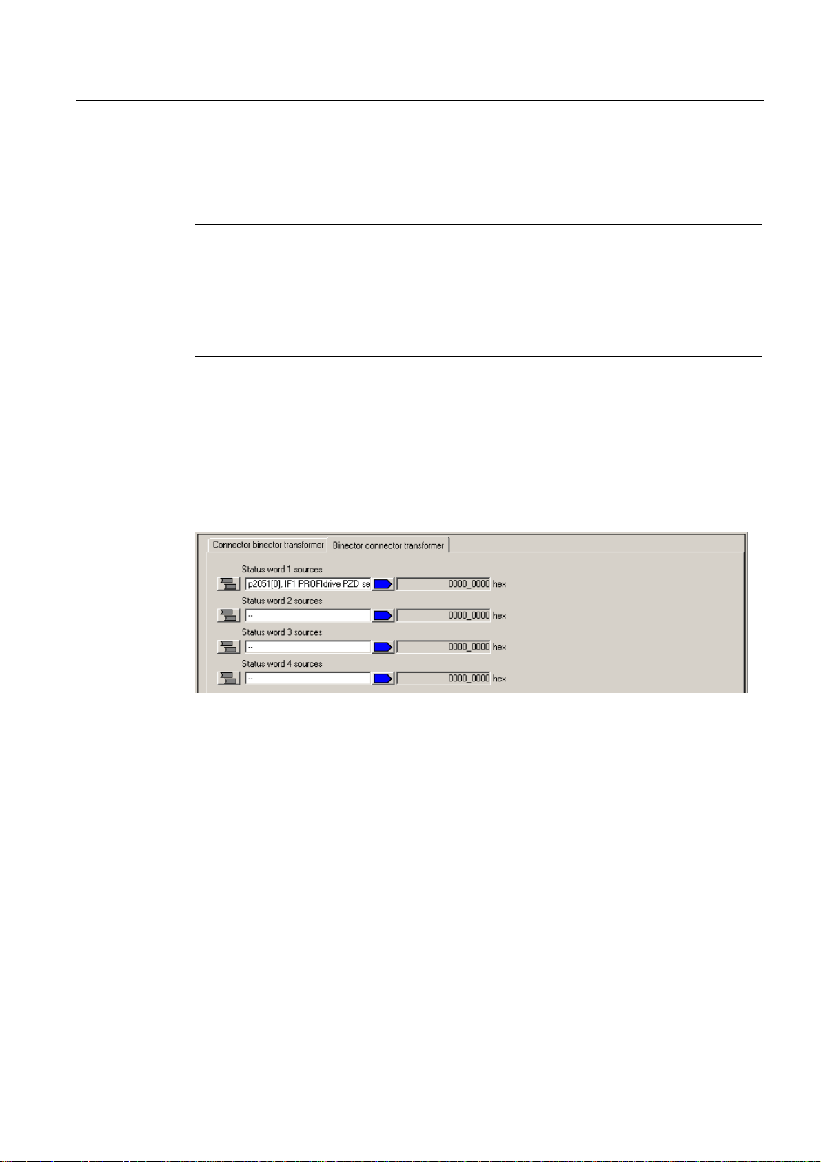
Commissioning (software)
4.6 Using drive-related I/Os by SIMOTION
Interconnecting the message frame for TM31
The next section describes how you can transfer signals from TM31 to SIMOTION
(PROFIBUS send direction).
Note
To perform interconnections in online mode, you must:
• Prior to the interconnection, download the message frame configuration into the target
device. Function: Download the CPU / drive device to the target unit.
• After the interconnection, download the settings from the target device into the
programming device / PC. Function: Download the CPU / drive unit to the programming
device.
1. Double-click the "PROFIBUS" entry in the "Communication" dialog of the TM31 you
created. The corresponding dialog box opens.
2. Click "Binector/connector converter" in the "PROFIBUS send direction" tab. The
"Binector/connector converter" tab opens
3. Select the source for status word 1 by clicking the "Source status word 1" field and then
select the corresponding PSD, in this example, TM31 -> p2051. . . Select PSD1.
Figure 4-24 Selecting the PSD
4. Click the button leading the "Source status word 1" field. The PSD bits are now displayed.
5. Click in a field and select the default signal, for example, bit 0.
This bit can be used, for example, to transmit the status at digital input DI 0 to
SIMOTION.
D410
Commissioning Manual, 08/2008 Edition
95
Page 96

Commissioning (software)
4.6 Using drive-related I/Os by SIMOTION
Figure 4-25 Selecting a signal
6. Interconnect all signals you need.
How to transfer a signal from SIMOTION to TM31 (PROFIBUS receive direction):
1. Double-click the "PROFIBUS" entry in the "Communication" dialog of the TM31 you
created. The corresponding dialog box opens.
2. Click "Binector/connector converter" in the "PROFIBUS receive direction" tab. The
"Connector/binector converter" tab opens
3. Interconnect all required signals. Proceed as defined in the description of the "PROFIBUS
send direction".
Creating an I/O variable in SIMOTION
Create the I/O variables in SIMOTION SCOUT in order to access the signals of TM31. You
require the input or output addresses for the TM31 message frame in the "PROFIBUS
Message Frame" dialog box. This allows you to assign the variable either as a complete
word, a byte or a single bit.
1. In the Project Navigator, double-click "I/O" below the created D410. The symbol browser
opens
2. Enter a name for the I/O variable.
3. Enter an I/O address, e.g.
PI277.0 - This accesses PSD1, bit 0 of the configured message frame.
PI276.0 - This accesses PSD1, bit 8 of the configured message frame.
SIMOTION can now access the signal.
The PROFIdrive profile specifies that the process status data (PSD) is defined as a 16-bit
value. Take into account when determining the I/O address that the least significant byte of
the SIMOTION I/O variable is assigned to the most significant PSD bits of the message
frame and vice versa:
I/O address Byte 276 Byte 277
Bytes represented in
bit format
PSD in bit
representation
7 6 5 4 3 2 1 0 7 6 5 4 3 2 1 0
15 14 13 12 11 10 9 8 7 6 5 4 3 2 1 0
D410
96 Commissioning Manual, 08/2008 Edition
Page 97

Commissioning (software)
4.6 Using drive-related I/Os by SIMOTION
4.6.5 Expanding a message frame
The message frame extension extends existing standard message frames (e.g. axis
message frames) with additional process status data (PSD). These additional PSDs are then
interconnected using BICO (e.g. to an actual speed value or to the status of a digital input).
A message frame extension is then the preferred variant when I/Os are to be distributed
between SIMOTION and SINAMICS and, for example, an axis view is preferred (driverelated I/O should be appended to each axis message frame).
Proceed as follows:
1. Insert a drive using the Drive Wizard and select PROFIBUS (drive), e.g. "standard
message frame 103", for process data exchange.
2. Double-click the "Configuration" entry below "SINAMICS Integrated" in the Project
Navigator in order to open the "PROFIBUS message frame" tab.
The tab contains the default length of I/O data for the drive you inserted. As the
addresses of I/O data have not yet been transferred to HW Config the default entry "???"
is set.
3. Select the row of the object of which you want to expand the message frame.
Figure 4-26 PROFIBUS message frame
4. Click "Add line" and select the "Message frame expansion" option in the menu shown.
A new line which contains the message frame expansion is inserted below the current
line.
5. Enter the "length" for the number of PSDs by which the message frame is to be extended
in the Input data and Output data columns.
D410
Commissioning Manual, 08/2008 Edition
97
Page 98

Commissioning (software)
4.6 Using drive-related I/Os by SIMOTION
Note
Before the matching, all drive objects without input/output addresses ("---..---") must be
moved behind the objects with valid input/output addresses or those still to be matched
("???..???").
The icons in the status column show the following information:
The message frame is configured differently in HW Config. You must match with HW
Config.
You use a predefined standard message frame or free BICO interconnection.
You use a changed standard message frame that you have extended with additional
data.
You use a message frame for which one of the two message frame lengths is too
long. The drive object cannot process this entry.
6. Click "Transfer to HW Config" in order to transfer the changes to HW Config.
The red check mark at the line indicates that a modified standard protocol is being used.
The I/O address data is entered after its transfer to HW Config.
7. Change to the configured drive and double-click the "PROFIBUS" entry in
"Communication".
8. Deactivate the "Hide inactive interconnections" option to display all PSDs of the message
frame.
The send and receive data (at least 16 entries) will be displayed. The first PSDs are
assigned the standard message frame by default and cannot be changed.
9. Interconnect the PSDs (at the end of the PSD list) that you have added with the required
signals by means of BICO.
D410
98 Commissioning Manual, 08/2008 Edition
Page 99

Commissioning (software)
4.6 Using drive-related I/Os by SIMOTION
Figure 4-27 Example: Interconnection of the onboard DI in the PROFIBUS send direction
Note
A warning message is not output if you interconnect more PSDs than were set in the
additional PSDs. Note that a SERVO drive object supports a maximum of 16 PSD
setpoints and 19 PSD actual values. Each VECTOR drive object supports a maximum of
32 PSD setpoints.
D410
Commissioning Manual, 08/2008 Edition
99
Page 100

Commissioning (software)
4.6 Using drive-related I/Os by SIMOTION
4.6.6 Using high-speed outputs for output cams on D410
Using high-speed outputs for output cams / DOs with D410
Output cams are defined as being the position-dependent output of switching signals. The
TO output cams and TO output cam track technology objects control the output of output
cams for SIMOTION.
The integrated digital outputs of the SIMOTION D can be used as cam output or as highspeed output with write access to the user program. In order to be able to use the highspeed outputs, one of the 39x message frames must be created.
Note
If I/O data is transferred using bus message frames, the update of the I/O data is subject to
the set bus cycle. This means an I/O using a 39x message frame can change its status just
once in each bus cycle of the PROFIBUS Integrated.
For SIMOTION D onboard outputs, the outputs are controlled using direct write accesses to
the hardware (i.e. bypassing the message frame). This means:
• Write accesses to digital outputs act with a particularly short delay time because the write
access is independent of the bus cycle.
• A more accurate output of the cam output is possible
For fast write accesses from the user program, the resulting delay time has the following
form:
• User program delay time -> terminal register: max. 75 μs
• Load-dependent output delay time of the hardware for D410:
L -> H: max. 400 μs
H -> L: max. 100 μs
High-speed outputs of output cams
If you use the output as high-speed output of a cam output, for the configuration of the TO
output cams / TO output cam track, enter the logical hardware address and the bit number of
the used output in the configuration screen form of the TO.
For additional information, see the
Outputs
Function Manual.
SIMOTION Motion Control Output Cams and Measuring
High-speed digital outputs
If you use the output as high-speed digital output, create an I/O variable in SIMOTION
SCOUT. The same addresses should be used for the high-speed digital outputs as those
normally used for the digital outputs.
D410
100 Commissioning Manual, 08/2008 Edition
 Loading...