

Page 1
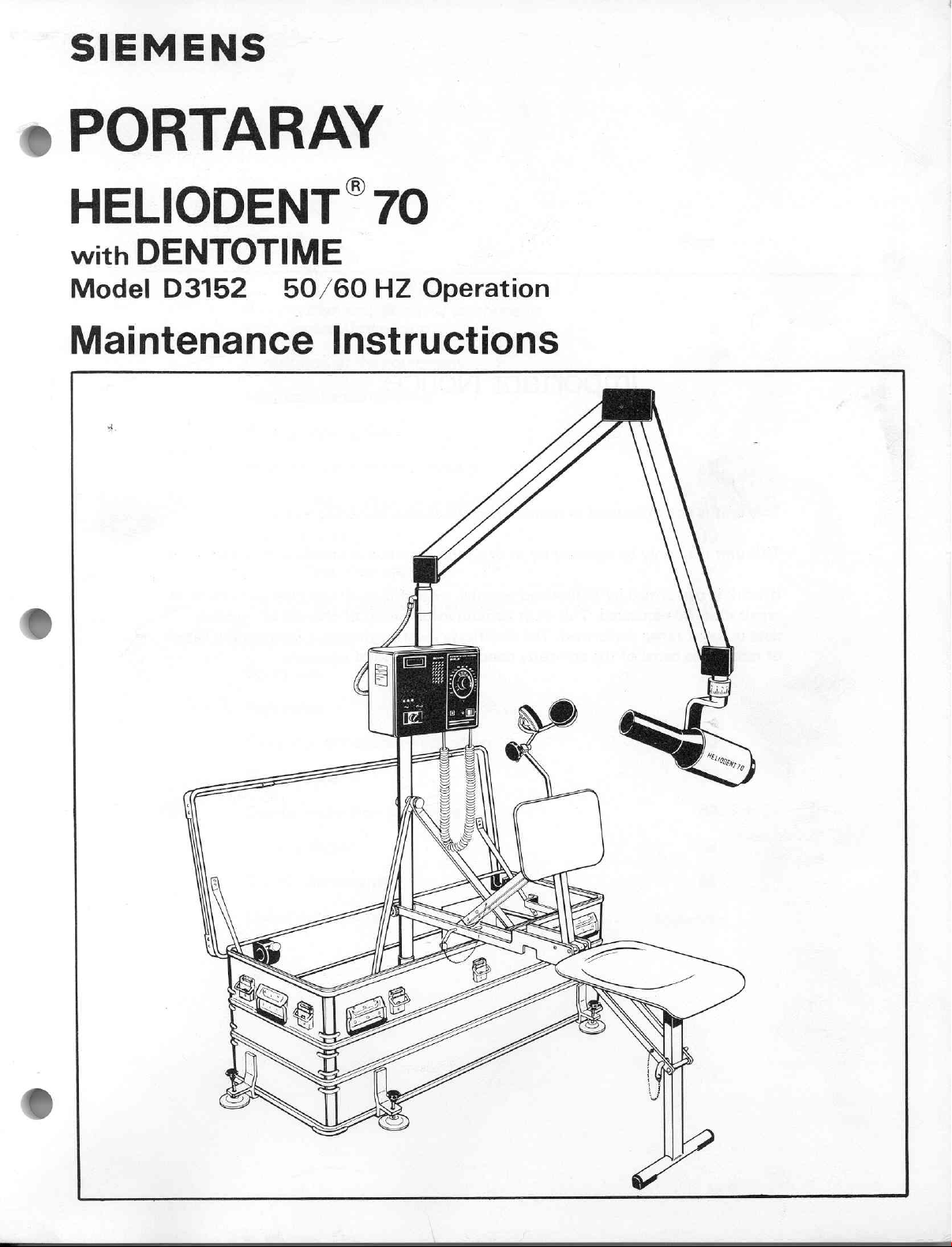
SIEMENS
PORTARAY
e
HELIODENT
with
Model
Maintenance
DENTOTIME
D3152
50/60
70
HZ
Instructions
Operation
Page 2

This
This
If
work
repair
data
of
repair,
unit
unit
must
or
is
not
may
is
performed
be
work
the
Important
to
be
used
only
be
repaired
by
authorized
reguested.
range
name
This
performed.
of
the
in
rooms
by
must
The
company
Notice
where
us
persons,
contain
certificate
concerned
an
or
a
representative
a
information
explosion
certificate
must
furthermore
and
a
valid
hazard
expressly
exists.
on the
of
changes
signature.
authorized
type
and
of
nominal
indicate
by
extent
the
date
us.
of
Page 3
Contents
X-ray
with
system
General
and
its
mayor
Description
components
Page
2
Description
Equipment
Physical
Assembly
Patient
Eguipment
of
the
equipment
specifications
description
instructions — Set-up
safety
and
care
other
Alerts / Troubleshooting
Accessories / Eguipment
Line
Adeguacy
Operation
Test
Repacking
Theory
Maintenance
Storage
or
principles
inspection
procedure
of
precautions
Warranty
operation
3
4
5
8
12
13
14
15
16
19
22
25
39
53
Cabling
diagram
DHHS - Statements
List
of
spare
parts
64
65
Appendix
Page 4
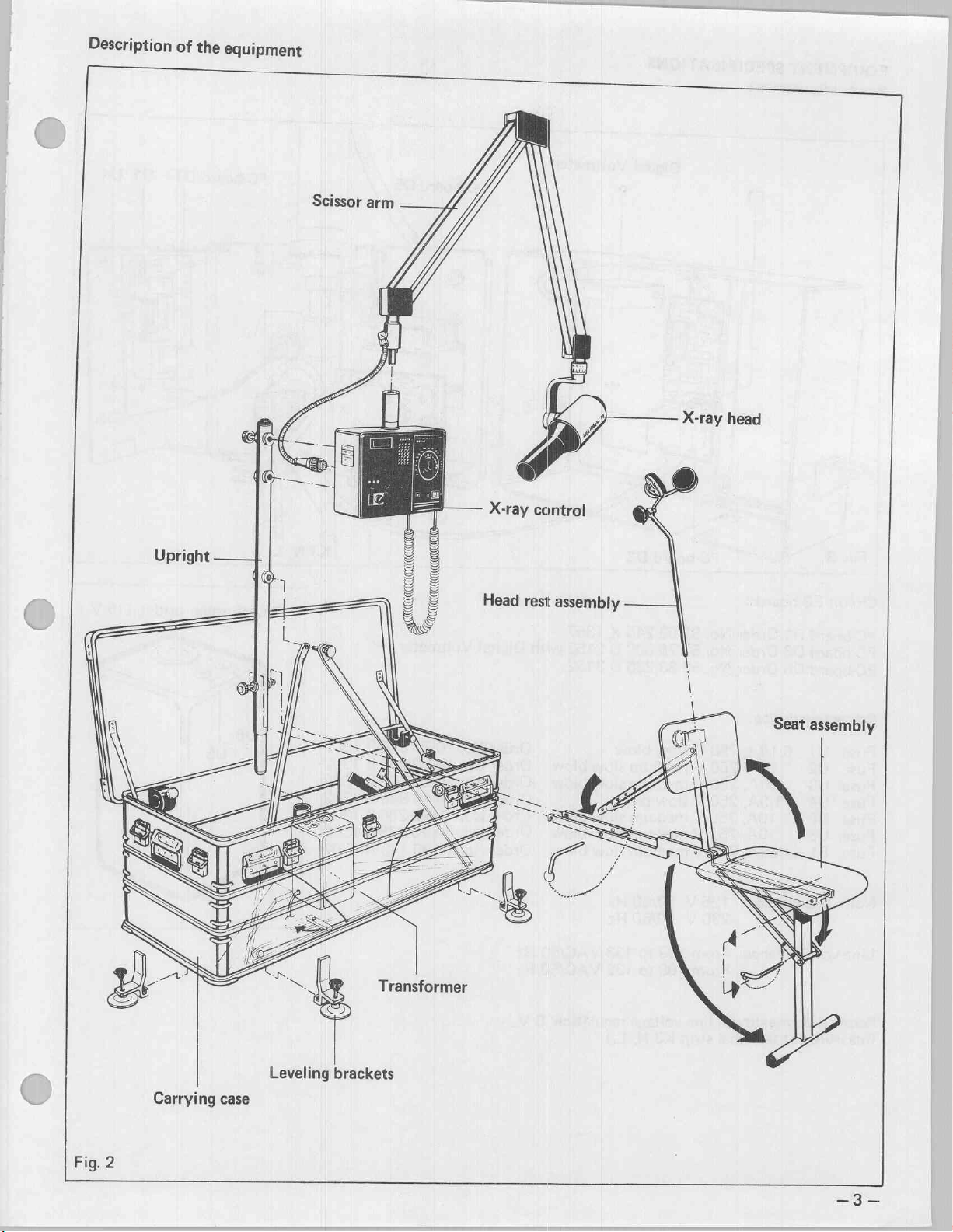
Description
=
of
the
equipment
X-ray
head
Seat
assembly
Carrying
Fig.
2
case
Leveling
Transformer
brackets
Page 5
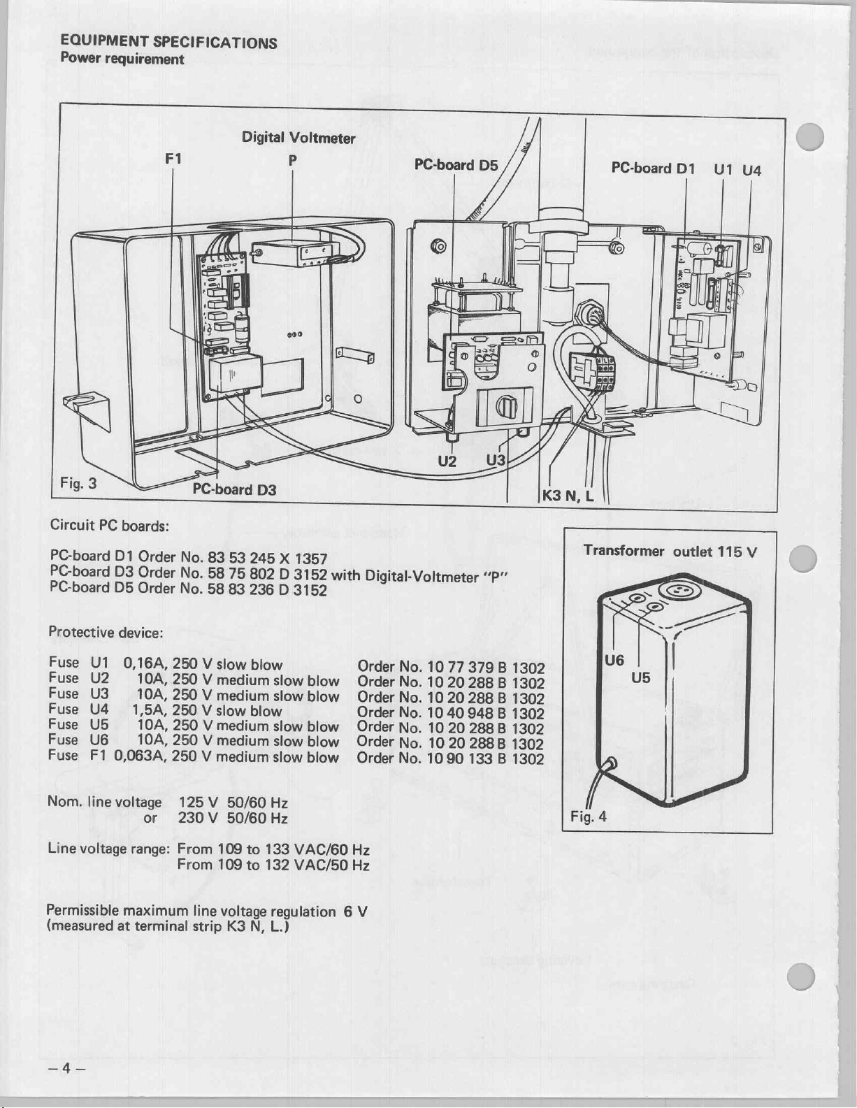
EQUIPMENT
Power
requirement
SPECIFICATIONS
Fig.
3
Circuit
PC
boards:
F1
Sig
X
PC-board
9
Digital
|
D3
Voltmeter
P
000
Ey
o
PC-board
D5
PC-board
D1
PC-board
PC-board
PC-board
Protective
Fuse
Fuse
Fuse
Fuse
Fuse
Fuse
Fuse
Nom.
Line
Permissible
(measured
D1
D3
D5
device:
U1
U2
U3
U4
|
U5
U6
F1
0,063A,
line
voltage
voltage
at
Order
Order
Order
0,16A,
10A,
10A,
1,5A,
10A,
10A,
or
range:
maximum
terminal
No.
83
53
No.
58
75
No.
58
83
250
V
slow
250
V
medium
250
V
medium
250
V
slow
250
V
medium
250
V
medium
250
V
medium
125 V 50/60
230V
From
From
109
109
line
strip
50/60
to
to
voltage
K3
245
X
1357
802
D
3152
236
D
3152
blow
slow
blow
slow
blow
blow
slow
blow
slow
blow
slow
blow
Hz
Hz
133
VAC/60
132
VAC/50
regulation 6 V
N,
L.)
with
Digital-Voltmeter
Order
No.
Order
No.
Order
No.
Order
©
Order
Order
Order
Hz
Hz
No.
No.
No.
No.
10
77
10
20
10
20
10
40
10
20
10
20
1090
“P”
379
288
288
948
288
288B
133
B
B
В
B
B
1302
B
1302
1302
1302
1302
1302
1302
Page 6
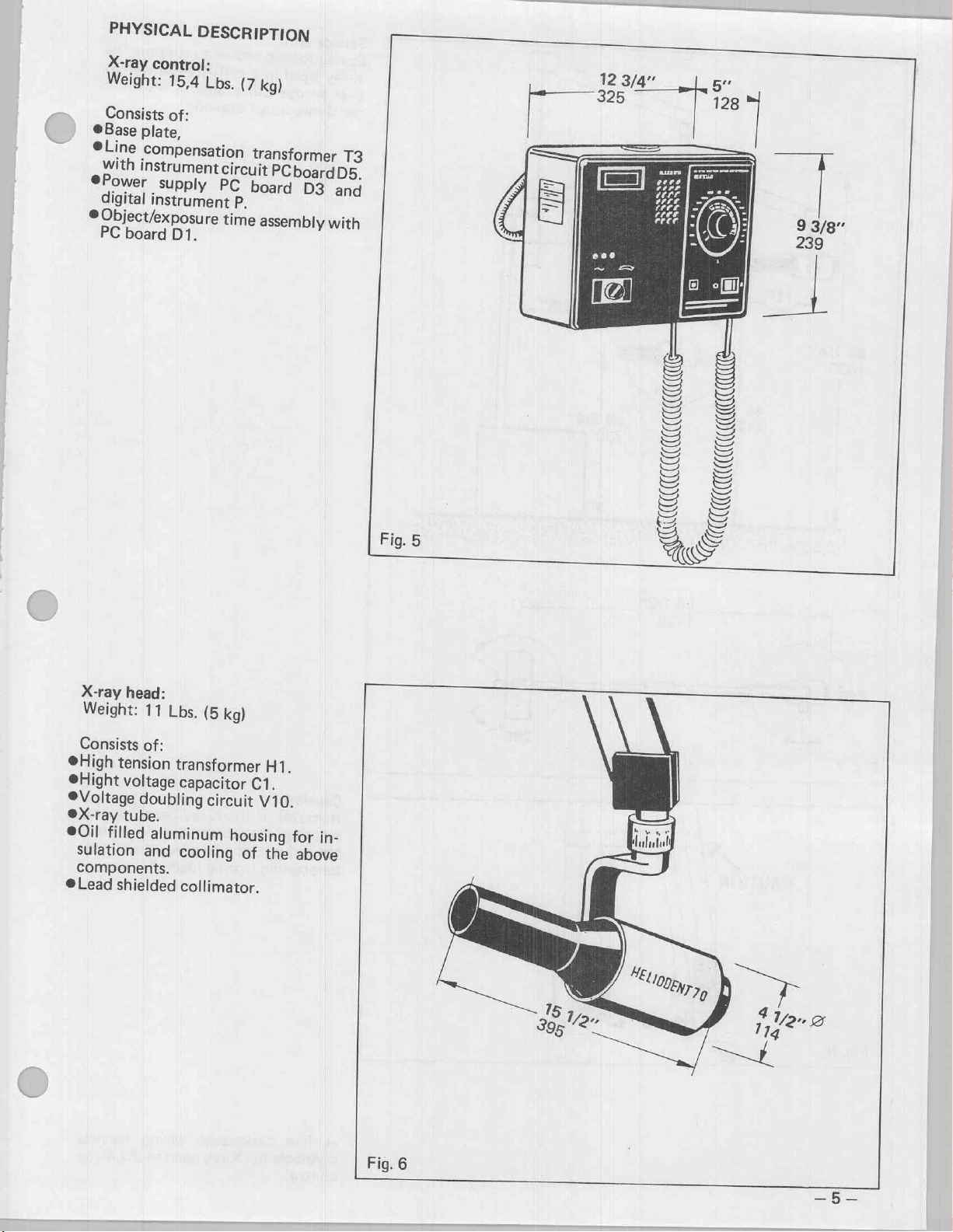
PHYSICAL
DESCRIPTION
Weight:
Consists
OBase
@Line
with
@Power
digital
©
Object/exposure
PC
15,4
of:
plate,
Compensation
instrument
supply
instrument
board
D1.
Lbs.
(7
circuit
PC
P.
time
kg)
transformer
PCboardD5.
board
D3
assembly
T3
and
with
Fig.
5
325
e
:
S
ミラ
E
SS
>
NSA
а
SE
S
Е
E
LÉ
128
>
に
ラ
RS
8
€
=
=
는
=
€
LS
=>
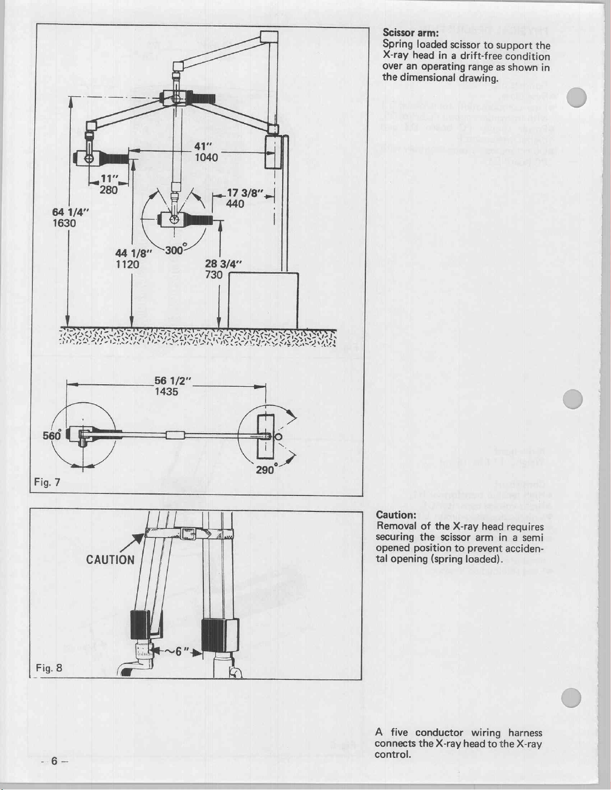
X-ray
head:
Weight:
Consists
@High
@Hight
Voltage
eX-ray
©0il
sulation
components.
@Lead
of:
tension
voltage
doubling
tube.
filled
and
shielded
11
Lbs.
transformer
capacitor
aluminum
cooling
collimator.
(5
kg)
C1.
circuit
housing
of
H1.
V10.
the
|
for
in-
above
Fig.
6
Page 7
Scissor
Spring
X-ray
over
the
head
an
dimensional
arm:
loaded
scissor
in
a
operating
to
support
drift-free
range
as
drawing.
the
condition
shown
in
56
1/2”
1435
STW
AIREY
-
の ン
IS
ささ
ペスト の いん
UN
ベン
2
Caution:
Removal
securing
opened
tal
opening
of
the
the
scissor
position
(spring
X-ray
arm
to
prevent
loaded).
head
in a semi
requires
acciden-
A
five
connects
control.
conductor
the
X-ray
wiring
head
to
harness
the
X-ray
Page 8
Patient
Weight:
Metal
treated
constructions
seat
seat
assembly;
30,8
and
Lbs.
(14
backrest.
kg)
with
pressure
41
1/4”
1050
Carrying
Weight
Support
Aluminum
tic
sistant
6
secured
The
with
with
structure:
polyurethane,
paint,
carrying
with
case
an
overpressure
case:
mounting
case
finished
color
handles.
10
is
waterproof
92,5
chemical
forest
The
lockable
valve.
devices
Lbs.
(42
with
alipha-
agent
green,
with
case
lid
latches.
and
fitted
and
kg)
re-
is
19
3/4”
500
47
1/4”
1200
Fig.
10
Page 9
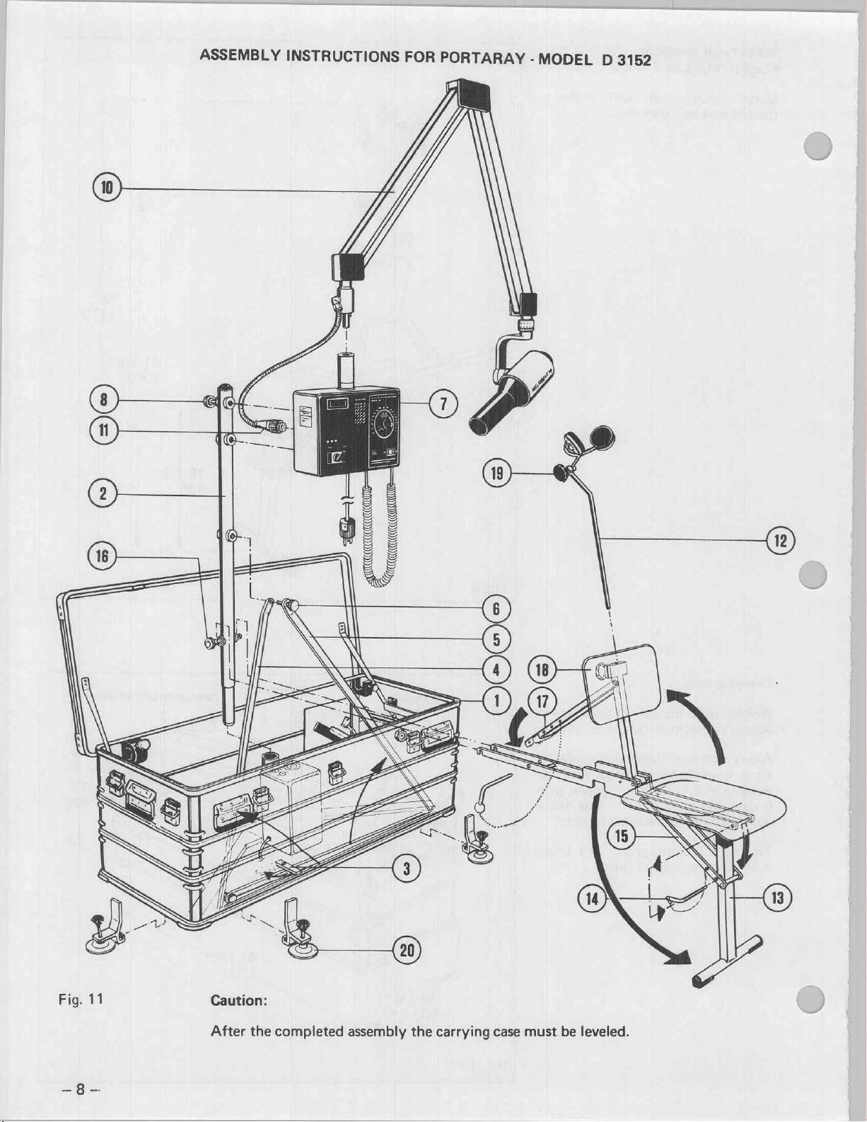
Fig.
11
Caution:
After
the
completed
assembly
the
carrying
case
must
be
leveled.
Page 10
_)
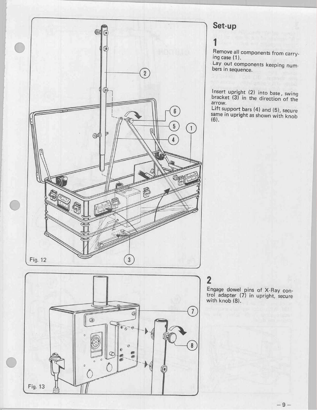
Set-up
1
Remove
ing
Lay
bers
all
(1).
case
out
components
in
sequence.
components
from
keeping
carry-
num-
Insert
bracket
arrow.
Lift
a
6).
upright
support
in
(3)
in
bars
upright
(2)
into
the
direction
(4)
and
as
shown
base,
(5),
with
swing
of
the
secure
knob
2
Engage
trol
with
dowel
adapter
knob
(8).
pins
(7)
of
in
upright,
X-Ray
con-
secure
Page 11

3
Loosen
a
6”
opening
before
pling
CAUTION!
opening
scissor
arm
safety
arm
Connect
with
engaging
as
damage.
strap
is
fully
lock
safety
of
shown.
To
of
arm,
completely,
engaged
multi
ring
strap
the
scissor
the
arm
prevent
the
spring
causing
DO
NOT
pin
plug
in
direction
(9)
to
in
accidental
injury
REMOVE
unless
in
the
(11)
permit
arm
(10)
the
cou-
loaded
and
the
coupling.
secure
of
arrow.
CAUTION
ine
^ ン 5
1
”
4
Loosen
assembly
Remove
stool
leg
(15).
With
secure
shown
see
knob
(12)
safety
(13)
stool
same
detail.
(18),
from
pin
and
leg
with
remove
storage
retainer
fully
headrest
position.
(14).
extended
safety
Unfold
bracket
pin
as
Page 12

eb
Engage
cure
rest
Position
brace
with
Insert
cure
height
stool
with
in
direction
(17)
safety
headrest
with
adjustment).
Support
knob
backrest
(3
Positions)
pin
(14a).
assembly
knob
(16).
of
arrow.
(18)
in
Raise
with
upright,
and
se-
back-
backrest
secure
(12),
(headrest
se-
TRANSFORMER
OUTLET
115
Adjust
with
headrest
knob
(19).
cradle
position
v
When
the
Connect
into
When
Connect
former's
the
the
230
In
case
diesel
rator
technical
Power
Volts:
Max.permissible
VAC
253
Max.
line
voltage
%
1.5
power
the
the
115
V
the
power
the
power
115
transformer's
V
wall
of
driven
must
rating:
230
permissible
at
meet
characteristics:
5
V
nominal,
during
VAC.
230
supply
power
wall
V
outlet.
a
portable
generator
kVA,
cord
outlet.
supply
cord
outlet
power
the
deviation:
fluctuation
standby:
is
115
directly
is
230
at
the
and
connect
cord
gasoline-
this
following
single
207
V:
V:
trans-
into
gene-
phase
to
of
6
Level
with
the
(20).
The
leveling
lower
carrying
carrying
aid
brackets
case
of
3-leveling
case
frame.
and
hook
upright
brackets
to
the
==
Page 13
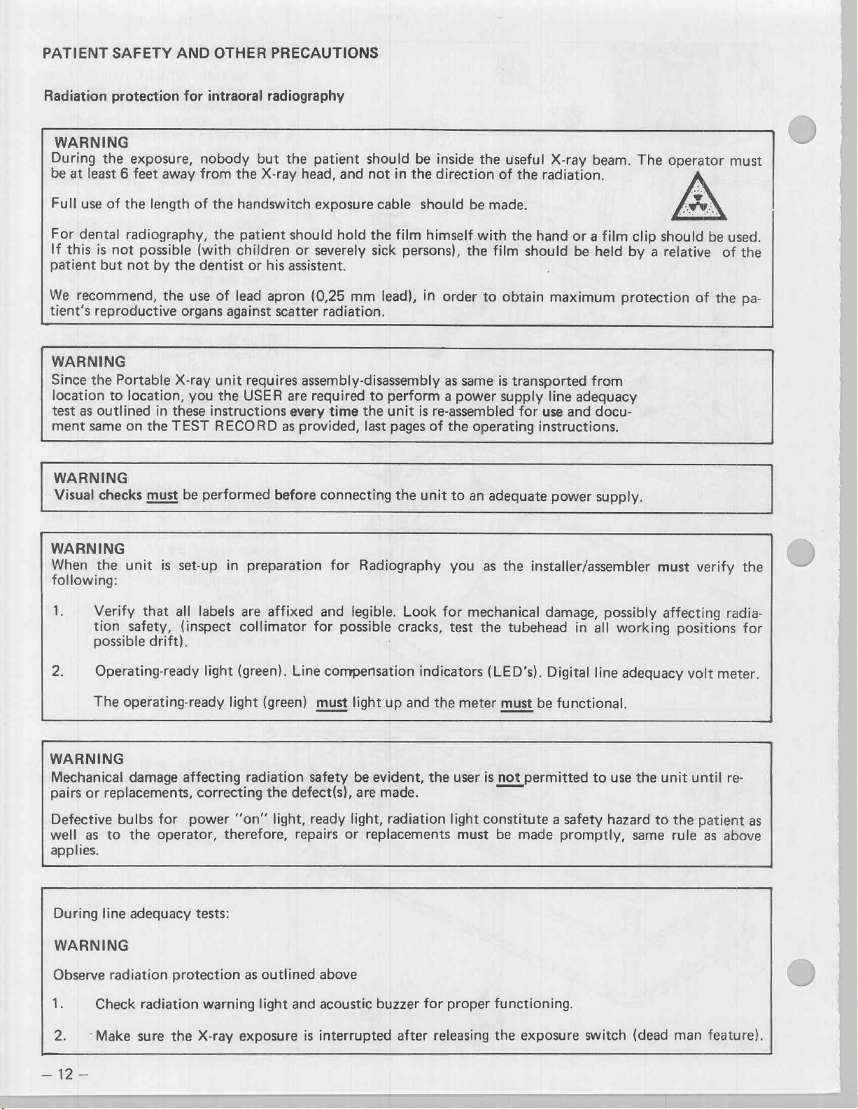
PATIENT
SAFETY
AND
OTHER
PRECAUTIONS
Radiation
WARNING
During
be
at
least 6 feet
Full
use
For
dental
If
this
patient
We
recommend,
tient's
WARNING
Since
the
location
test
as
ment
same
WARNING
Visual
WARNING
When
following:
protection
the
exposure,
away
of
the
length
radiography,
is
not
possible
but
not
reproductive
Portable
to
location,
outlined
on
checks
the
unit
by
the
in
the
must
is
the
these
TEST
for
intraoral
nobody
from
of
the
the
(with
dentist
use
of
organs
X-ray
unit
you
the
instructions
RECORD
be
performed
set-up
radiography
but
the
X-ray
handswitch
patient
children
his
or
lead
apron
against
in
scatter
requires
USER
before
preparation
the
patient
head,
exposure
should
or
severely
assistent.
(0,25
radiation.
assembly-disassembly
are
required
every
as
provided,
connecting
should
and
not
hold
the
sick
mm
to
time
the
last
for
Radiography
cable
lead),
be
inside
in
the
direction
should
film
himself
persons),
in
perform a power
unit
is
re-assembled
pages
of
the
unit
the
order
as
same
the
to
an
you
be
the
with
to
operating
as
useful
of
the
made.
the
hand
film
should
obtain
is
transported
supply
for
instructions.
adequate
the
installer/assembler
X-ray
beam.
radiation.
or
a film
be
held
maximum
from
line
adequacy
use
and
docu-
power
supply.
The
operator
clip
should
by
a
relative
protection
must
must
be
used.
of
of
the
verify
the
pa-
the
ir
Verify
tion
possible
2.
WARNING
Mechanical
pairs
Defective
well
applies.
Operating-ready
The
or
as
During
WARNING
Observe
k
Check
that
all
safety,
drift).
operating-ready
damage
replacements,
bulbs
for
to
the
operator,
line
adequacy
radiation
protection
radiation
labels
(inspect
affecting radiation
correcting
power
tests:
are
collimator
light
(green).
light
“on”
therefore,
as
warning
affixed and
Line
(green)
the
defect(s),
light,
repairs
outlined
light
and
legible.
for
possible
compensation
must
light
safety
ready
be
are
light,
or
replacements
above
acoustic
evident,
Look
cracks,
|
indicators
up
and
made.
radiation
buzzer
the
the
for
for
mechanical
test
the
tubehead
(LED’s).
meter
must
user
is
not
light
constitute a safety
must
be
made
proper
functioning.
damage,
in
Digital
be
functional.
permitted
promptly,
possibly
all
working
line
adequacy
to
use
hazard
the
to
same
affecting
positions
volt
unit
until
the
patient
rule
as
radia-
for
meter.
re-
as
above
2.
Make
=D
sure
the
X-ray
exposure
is
interrupted
after
releasing
the
exposure
switch
(dead
man
feature).
Page 14
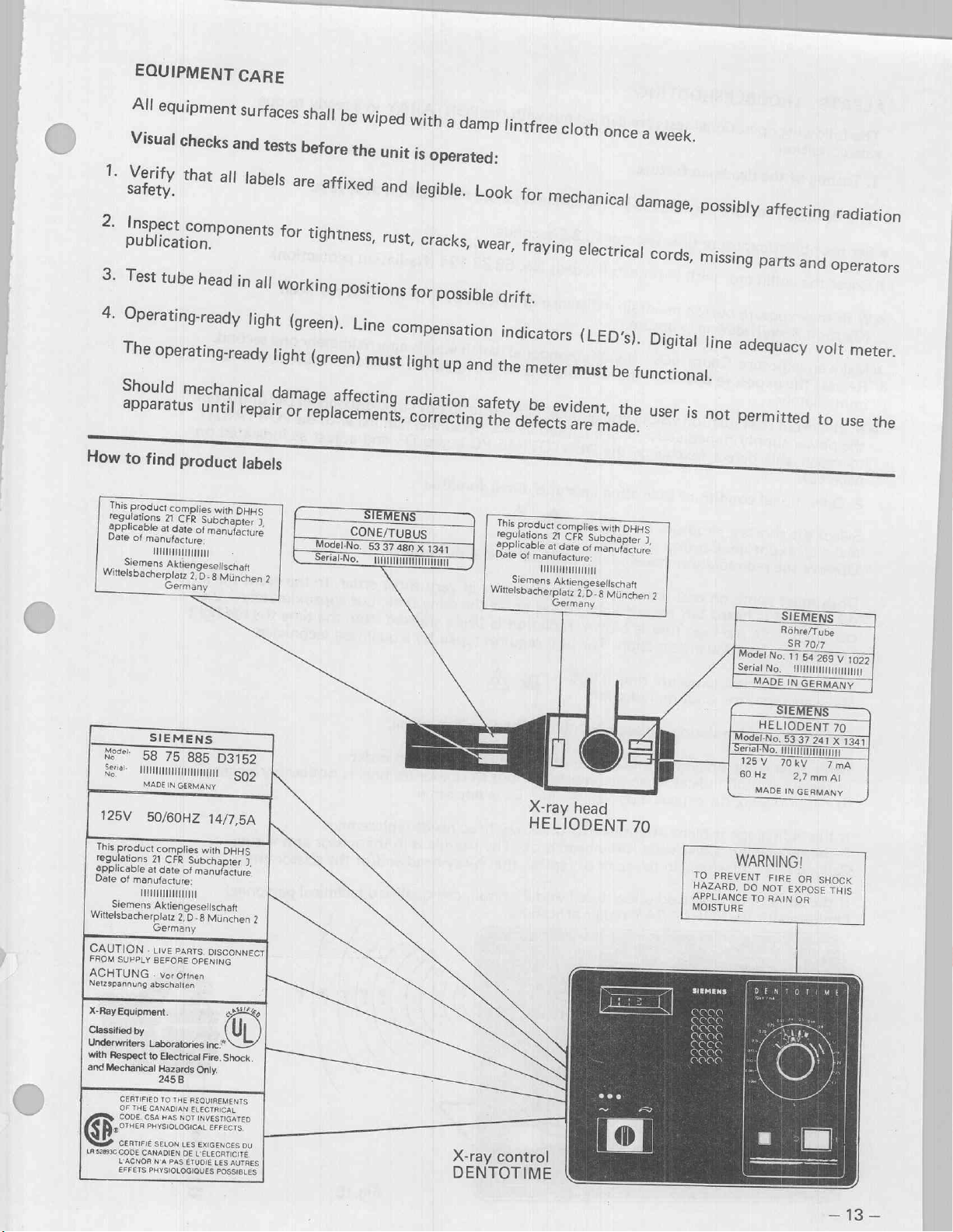
EQUIPMENT
All
equipment
Visual
2.
Inspect
E
li
3
Test
4.
Operating-ready
The
Operating-ready
Should
How
to
Wittelsbacherplatz
find
This
product
regulations
applicable
Date
of
manufacture
Siemens
НИИ
checks
Components
È
ion.
tube
head
mechanical
product
complies
CFR
date
with
Subchapter
of
manufacture
2.D-8
München
21
at
Aktiengesellschaft
Germany
CARE
surfaces
and
tests
in
all
Working
light
light
damage
labels
DHHS
J,
2
shall
before
or
tightness
(green).
(green)
Model-No.
Serial-No,
be
wiped
the
positions
Line
with
unit
is
Operated:
rust,
7
cracks,
r
or
Compensation
must
light
a
damp
7
possible
up
and
affecting radiation
5337
TI
480
X
1341
wea
lintfree
„
drift.
aying
Tr
Ying
cloth
indicators
the
meter
safety
be
evident,
This
product
regulations
applicable
Date
Witelsbacherplatz
complies
21
CFR
at
date
of
manufacture:
11111
Siemens
Aktiengesellschaft
Germany
once
el
ectrical
rica
(LED).
must
be
the
with
Subchapter
of
manufacture
2,D-8
München
a
week.
co
r
ds,
Digital
functional.
user
is
DHHS
)
2
missin
!
line
not
Ing
part:
arts
ar
adeguacy
permitted
d
ope
volt
to
r
ators
meter.
use
the
r
SIEMENS
Nec
58
Sere
MO
Wittelsbacherplatz
CAUTION
FROM
ACHTUNG
Netzspannung
X-Ray
Classified
Underwriters
with
and
G
LA
MADE
125V
50/60HZ
This
product
regulations
applicable
Date
pame
528936
21
at
of
manufacture:
Hi
Siemens
Germany
-
SUPPLY
.
abschalten
Equipment
by
Laboratories
Respect
to
Mechanical
CERTIFIED
OF
THE
CANADIAN
CODE.
CSA
PHYSIOLOGICAL
CERTIFIÉ
CODE
CANADIEN
L'ACNOR
N'A
EFFETS
PHYSIOLOGIOUES
LIVE
BEFORE
vor
75
885
D3152
IN
GERMANY
complies
CFR
date
of
Aktiengesellschaft
2,D-8
PARTS.
ottnen
Electrical
Hazards
245B
TO
THE
HAS
NOT
SELON
LES
DE
PAS
ÉTUDIE
S02
14/7,5A
with
DHHS
Subchapter
manufacture
OPENING
Only.
REQUIREMENTS:
ELECTRICAL
INVESTIGATED
EXIGENCES
L'ÉLECRTICITÉ
J,
Munchen
DISCONNECT|
LG
inc.”
Fire.
Shock.
EFFECTS,
OÙ
LES
AUTRES
POSSIBLES.
2
X-ray
DENTOTIME
X-ray
HELIODENT
control
head
T
7
70
TO
PREVENT
HAZARD,
APPLIANCE
Nd
Model
No.
Serial
No.
MADE
HELIODENT
Model-No.
erial-No.
TRN
125V 70kV
60
Hz
MADE
WARNING!
FIRE
DO
NOT
TO
RAIN
:
SR
70/7
11
54
HUTT
IN
GERMANY
53
37
2,7
mm
IN
GERMANY
OR
EXPOSE
GR
269
V
1022
70
241
X
1341
7
mA
AI
SHOCK
THIS
Page 15

ALERTS / TROUBLESHOOTING
The
following
rate
condition.
1.
Testing
The
deadman
e
Set the
e
Cover
®
With
(Caution
©
Make
Release
immediately,
e
In
the
to
page
2.
object/exposure
the
the
an
the
the
event
power
repair
43).
Operational
operational
of
the
deadman
feature
collimator
exposure
X-ray!)
exposure.
supply
this
during
exposure
the
radiation
immediately
defect
conditions
permits
time
with
button
exposure.
Count
button
(exchange
tests
are
carried
feature
the
premature
selector
cover
cap
(leaded)
maintain
5001
—
visible
indicating
a
(fivethousandone)
the
audible
and
audible
—
call
qualified
the
DENTOTIME
improper
out
to
3.2
seconds.
distance
and
with
the
immediate
No.
58
83
of
at
least
which
visible
indicators
service
timer
personnel
PC
function
PORTARAY
termination
194
(Radiation
6FT
from
equals
radiation
do
board
approximately
not
stop,
familiar
D1
in a ready
of
X-rays.
protection).
the
X-ray
indicators
disconnect
with
and
adjust
head
must
the
the
as
to
ope-
one
second.
terminate
unit
PORTARAY
indicated
from
on
Select
Make
the
an
Observe
Both
must
dible
signal
cond
later
comes
Select
Make
Observe
Both
In
(0.7
If
If
Call
If
familiar
on
the
an
must
the
event
to
the
radiograph
the
radiograph
a
qualified
the
conditions
shortest
exposure.
the
red
come
is
heard
the
—
insufficient
shortest
exposure.
the
red
come
both
1.0
second),
the
with
exposure
Caution
radiation
on
and
but
pre-heat
exposure
Caution
radiation
on
and
indicators
expose a periapical
is
blank
is
black
technician
described
PORTARAY
SIEMENS
time
radiation.
emission
terminate
no
fuse
emission.
time
radiation.
emission
terminate
come
(transparent)
the
to
under
0.066. > A
light
simultaneously
red
light
comes
is
blown,
X-ray
repair
repair
radiation
The
unit
0.066.
light(visualland
simultaneously
on
together
the
head
or
replace
test
1
and
procedure.
ΡΕΝΤΟΤΙΝΜΕ
!
(visual)
film.
is
and
on
requires
p
but
Develope
X-ray
ok.
The
the
2
prevail,
audible
in
at
the
is
being
repair
audible
in
very
the
head
trouble
X-ray
call
signal.
very
short
same
time,
emitted
by
a
signal.
short
exposure
same.
needs
replacement.
is
in
head
and/or
qualified
order.
but
approximately
from
the
qualified
order.
time
is
noticeably
the
scissor
the
technical
\
In
the
event
time
the
technician.
longer
arm
wiring.
scissor
arm.
personnel
the
1/2
red
au-
se-
light
Fig.18
-
=
=
Page 16
è
esi
Fig.19
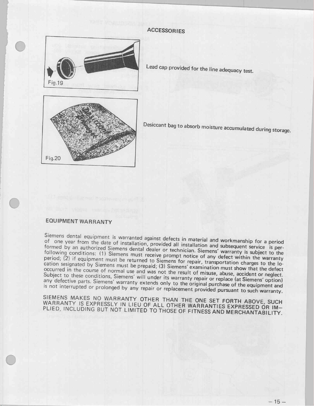
ACCESSORIES
Lead
cap
provided
for
the
line
adequacy
test.
EQUIPMENT
Siemens
of
formed
following
period;
cation
Occurred
Subject
any
is
not
SIEMENS
WARRANTY
PLIED,
dental
one
year
b
y
conditions:
(2)
sesignated
in
to
these
defective
interrupted
MAKES
INCLUDING
WARRANTY
equipment
from
an
authorized
if
equipment
by
the
course
conditions,
parts.
IS
EXPRESSLY
the
date
(1)
Siemens
of
Siemens’
or
prolonged
NO
BUT
is
warranted
of
installation,
Siemens
Siemens
must
be
must
normal
Siemens’
warranty
by
WARRANTY
IN
NOT
LIMITED
Desiccant
bag
dental
must
returned
be
prepaid;
use
and
will
extends
any
repair
OTHER
LIEU
OF
against
dealer
receive
was
under
defects
provided
or
prompt
to
Siemens
(3)
Siemens’
not
its
only
or
replacement
THAN
ALL
TO
OTHER
THOSE
all
technician.
the
warranty
to
to
absorb
in
installation
notice
for
result
the
THE
OF
moisture
material
Siemens’
of
repair,
examination
of
misuse,
repair
original
provided
ONE
WARRANTIES
FITNESS
accumulated
and
workmanship
and
subsequent
warranty
any
defect
transportation
abuse,
or
replace
purchase
pursuant
SET
AND
within
must
show
accident
(at
of
the
FORTH
EXPRESSED
MERCHANTABILITY.
during
for
service
is
subject
the
charges
that
Siemens’
equipment
to
such
warranty.
ABOVE,
storage.
a
period
is
per-
to
warranty
to
the
the
defect
or
neglect.
option)
and
SUCH
OR
IM—
the
lo-
io
Page 17
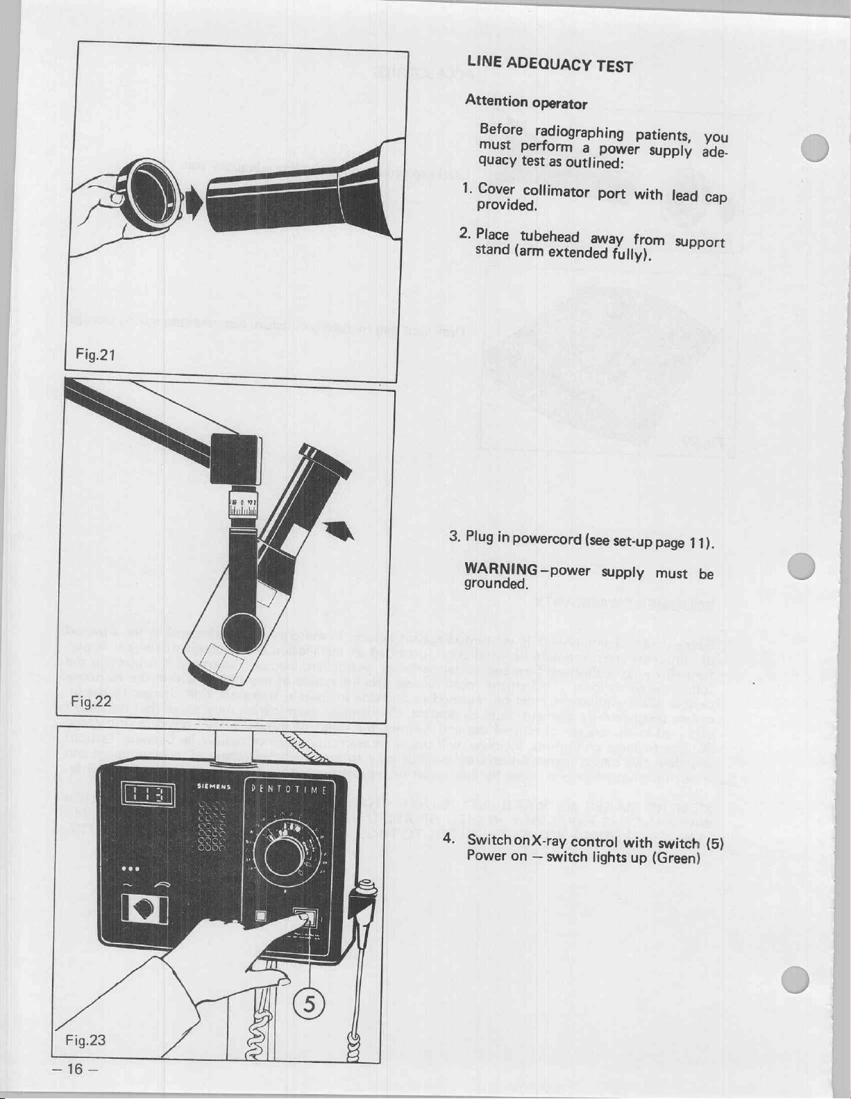
LINE
ADEQUACY
TEST
Fig.21
Attention
1.
2.
stand
Operator
Before
must
quacy
Cover
provided.
Place
perform
test
collimator
tubehead
(arm
radiographing
a
as
extended
power
outlined:
port
away
fully).
patients,
Supply
with
lead
from
support
you
ade-
cap
À
SÅ
Fig.22
3.
Plug
in
WARNING
grounded.
4.
SwitchonX-ray
Power
powercord
—power
on
—
switch
(see
set-up
supply
control
lights
with
up
page
must
switch
(Green)
11).
be
(5)
—
Page 18

109
-
133
V
(60
109
-
132
V
Fig.24
(50
Hz)
Hz)
5.
The
digital
read
between:
min
109,0
min
109,0
After
5
instrument,
rating
Instructions,
pow
v
V
minutes
on
er
supply
note
value
test
record
appendix).
test
133,0
132,0
displayed
(test
instrument
V
max.
at
V
max.
at
on
records
60
50
the
see
must
HZ
HZ
test
Ope-
6.
Verify
Yellow
(too
Corrections
Yellow
Red
CAUTION
call
Operate
(See
-
Select
turning
line)
Do
symbols.
that
low)
are
=
Turn
=
Turn
—
medical
Maintenance
with
not
If
maintenance
apparatus.
an
exposure
knob
3.2
on
depress
the
Green
(O.K)
made
switch
switch
green
(9)
to
scale.
knob
green
page
light
with
clockwise
counterclockwise
light
41).
time
align
when
(too
switch
will
Personnel
of
adult
aligning
diode
Red
High)
(7)
not
come
—
3.2
seconds
symbol
adult/child
(8)
is
on,
DO
NOT
(orange
lit:
by
17
—
Page 19
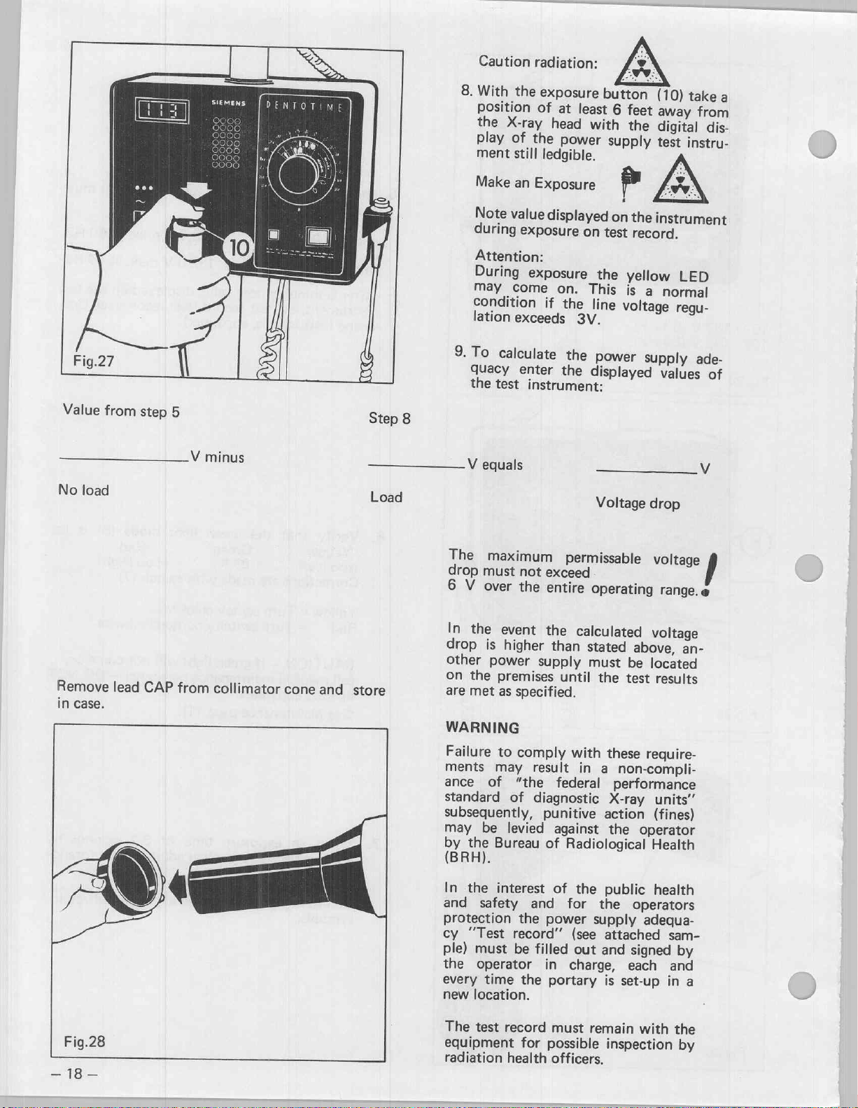
Caution
radiation:
8.
With
the
position
the
play
ment
Make
Note
during
Attention:
During
may
condition
lation
of
X-ray
of
the
still
an
Exposure
value
exposure
exposure
come
exceeds
exposure
at
head
power
ledgible.
displayed
on.
if
the
3V.
button
least
with
supply
on
test
the
This
line
6
feet
the
p
on
the
record.
yellow
is
a
voltage
(10)
take
away
from
digital
test
instrument
normal
dis-
instru-
LED
regu-
a
ré
È
Fig.27
Value
No
Remove
in
load
case.
©
from
lead
ia
step
CAP
4
5
V
from
minus
collimator
cone
and
Step
Load
store
8
9.To
The
drop
6
In
drop
other
on
are
WARNING
Failure
ments
ance
standard
subseguently,
may
by
(BRH).
In
and
protection
cy
ple)
the
every
new
calculate
quacy
the
test
V
equals
maximum
must
V
over
the
event
is
higher
power
the
premises
met
as
specified.
to
may
of
of
be
levied
Bureau
the
the
interest
safety
“Test
record”
must
be
operator
time
location.
enter
not
the
comply
“the
the
the
the
the
instrument:
exceed
entire
the
supply
result
diagnostic
punitive
of
and
power
filled
in
portary
displayed
permissable
operating
calculated
than
stated
must
until
with
in
federal
against
Radiological
of
the
for
(see
out
charge,
power
Voltage
above,
be
the
test
these
a
non-compli-
performance
X-ray
action
the
operator
public
the
operators
supply
attached
and
signed
each
is
set-up
supply
values
drop
voltage
range.
voltage
an-
located
results
reguire-
units“
(fines)
Health
health
adequa-
sam-
by
and
in
a
ade-
of
e
)
>
Fig.28
2
—
18
—
The
eguipment
radiation
test
record
for
health
must
remain
possible
officers.
inspection
with
the
by
Page 20
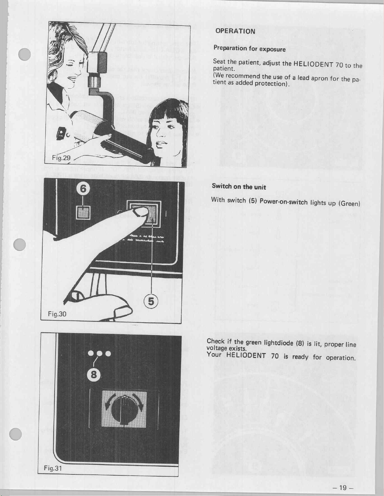
OPERATION
Preparation
Seat
the
patient,
patient.
(We
recommend
tient
as
added
Switch
With
on
switch
for
exposure
adjust
the
protection).
the
unit
(5)
Power-on-switch
use
the
HELIODENT
of
a
lead
apron
lights
70
for
up
to
the
the
pa-
(Green)
Fig.31
Check
voltage
Your
HELIODENT
if
the
exists.
green
lightdiode
70
is
(8)
ready
is
lit,
proper
for
operation.
—
line
19
—
Page 21
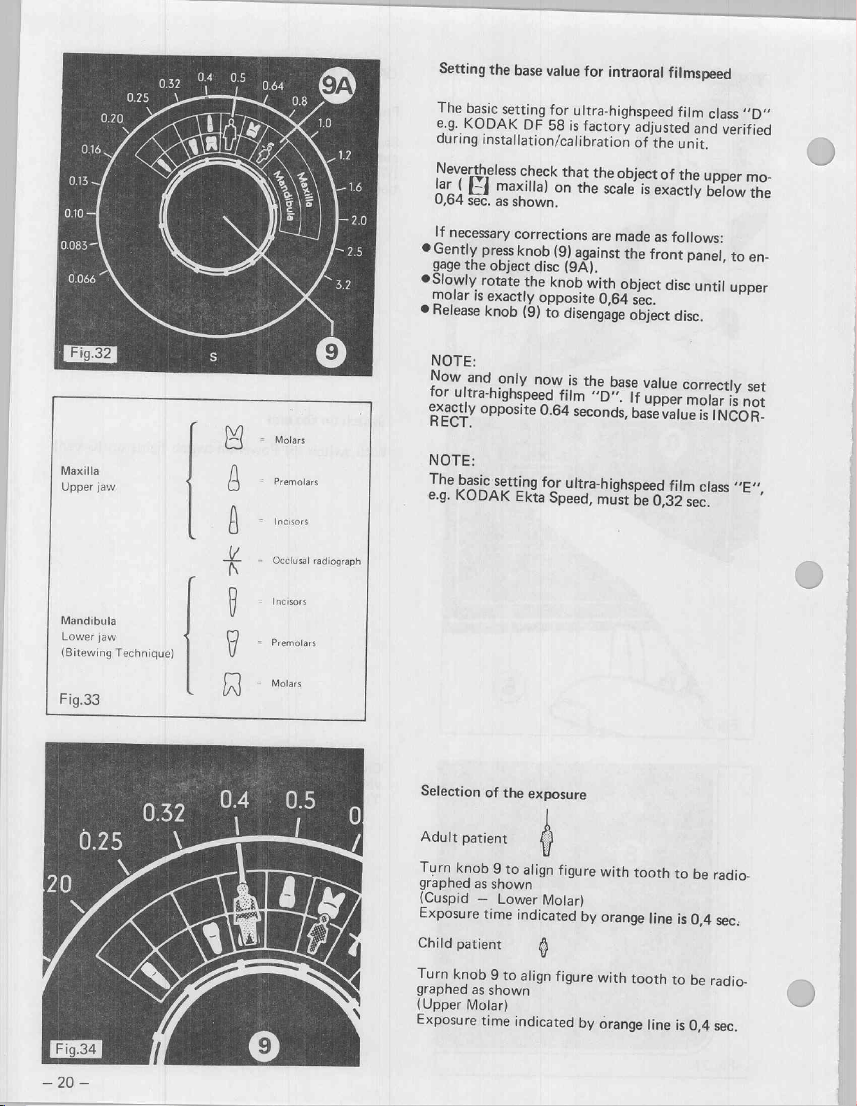
Setting
The
basic
e.g.
KODAK
during
the
base
value
for
intraoral
setting
installation/calibration
DF
for
ultra-highspeed
58
is
factory
adjusted
of
filmspeed
film
and
the
unit.
class
verified
“D“
Maxilla
Upper
jaw
fe
f=
c=
ラド
=
Molars
-
Premolars
=
Incisers
Occlusal
radiograph
Nevertheless
lar
(
E
0,64
sec.
If
necessary
©
Gently
gage
©
Slowly
molar
©
Release
NOTE:
Now
for
exactly
RECT.
NOTE:
The
e.g.
press
the
rotate
is
knob
and
ultra-highspeed
opposite
basic
KODAK
check
maxilla)
as
shown.
corrections
knob
object
exactly
disc
the
(9)
only
setting
Ekta
that
the
on
the
scale
are
(9)
against
(9A).
knob
with
opposite
to
now
0.64
for
Speed,
0,64
disengage
is
the
film
“D”.
seconds,
ultra-highspeed
must
object
made
the
object
sec.
object
base
If
base
be
of
is
exactly
as
follows:
front
disc
value
upper
value
film
0,32
the
upper
below
panel,
until
disc.
correctly
molar
is
INCOR-
class
sec.
mo-
the
to
en-
upper
set
is
not
SEM,
Mandibula
Lower
jaw
(Bitewing
Fig.33
Technique)
4
ニコ
|
の
ご
2
=
Incisors
Premolars
Molars
Selection
Adult
Turn
graphed
(Cuspid
Exposure
Child
Turn
graphed
(Upper
Exposure
of
patient
knob
as
—
time
patient
knob
9
as
shown
Molar)
time
the
9
to
align
shown
Lower
indicated
to
align
indicated
exposure
0
figure
Molar)
@
figure
by
by
with
orange
with
tooth
orange
tooth
line
line
to
is
to
is
be
0,4
be
0,4
radio-
sec.
radio-
sec.
Page 22
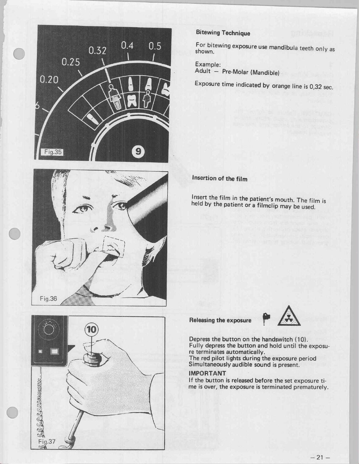
Bitewing
For
bitew
Example:
Adult
—
Technique
ng
exposure
Pre-Molar
use
mar
dibula
(Mandible)
teeth
onl
as
y
Exposure
Insertion
Insert
the
held
by
the
time
of
the
film
patient
indicated
film
in
i
the
patient's
or
a
by
orange
mouth.
filmclip
may
line
:
The
be
used.
is
film
0,32
mi
sec.
i
°
Sit
Depress
Fully
re
terminates
The
Simultaneously
IMPORTANT
If
the
me
is
cca
the
button
depress
red
pilot
button
over,
the
the
button
automatically.
lights
audible
is
released
exposure
on
the
and
during
sound
before
is
handswitch
hold
until
the
exposure
is
present.
the
set
terminated
(10).
the
exposu-
period
exposure
prematurely.
ti-
20
Page 23
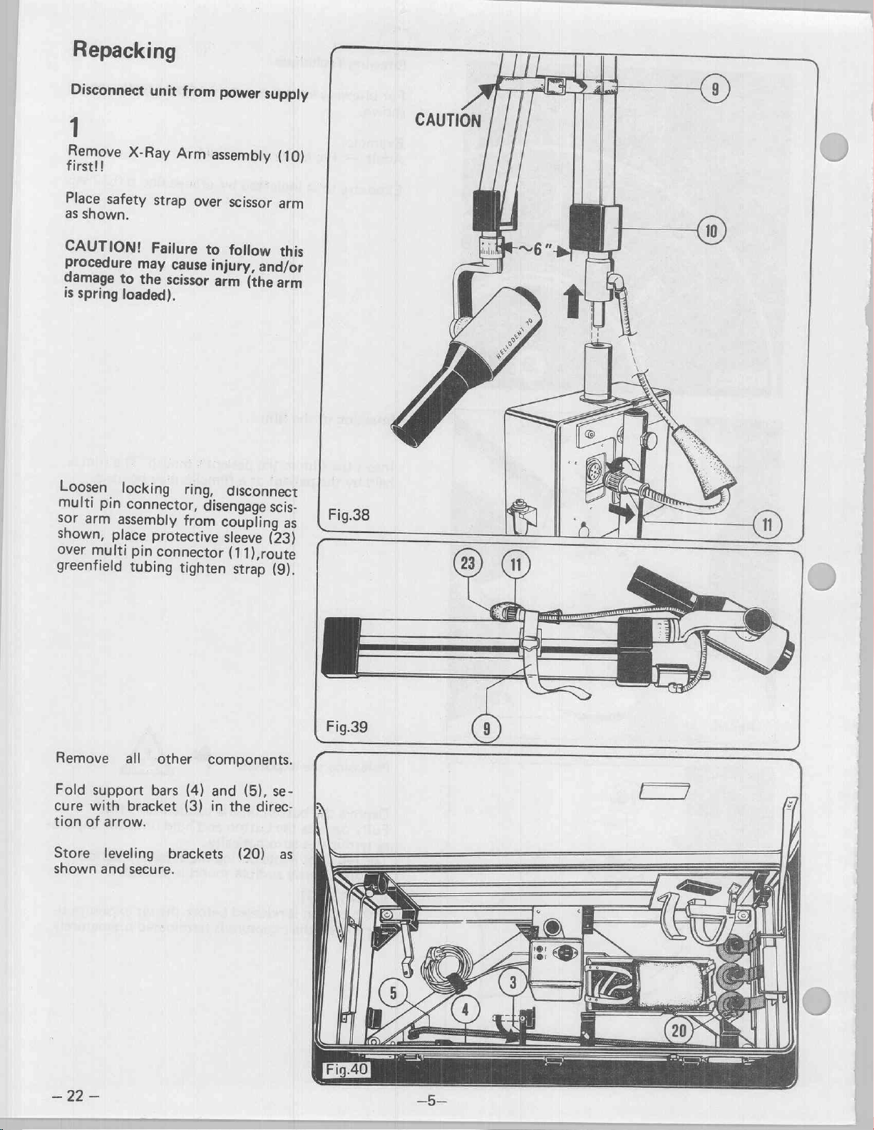
Repacking
Disconnect
1
Remove
first!!
X-Ray
unit
from
Arm
power
assembly
supply
CAUTION
(10)
Place
safety
as
shown.
CAUTION!
Procedure
damage
is
Loosen
multi
Sor
shown,
Over
greenfield
spring
pin
arm
place
multi
to
loaded).
locking
assembly
strap
over
Failure
may
cause
the
scissor
connector,
pin
tubing
ring,
from
protective
connector
tighten
scissor
to
follow
injury,
arm
disengage
and/or
(the
disconnect
coupling
sleeve
(11),route
strap
arm
this
arm
scis-
as
(23)
(9).
=
li
NEW
23
i
10
Remove
Fold
cure
tion
of
Store
shown
all
support
with
bracket
arrow.
leveling
and
secure.
other
bars
(4)
(3)
brackets
components.
and
(5),
se-
in
the
direc-
(20)
as
一
22
一
Page 24
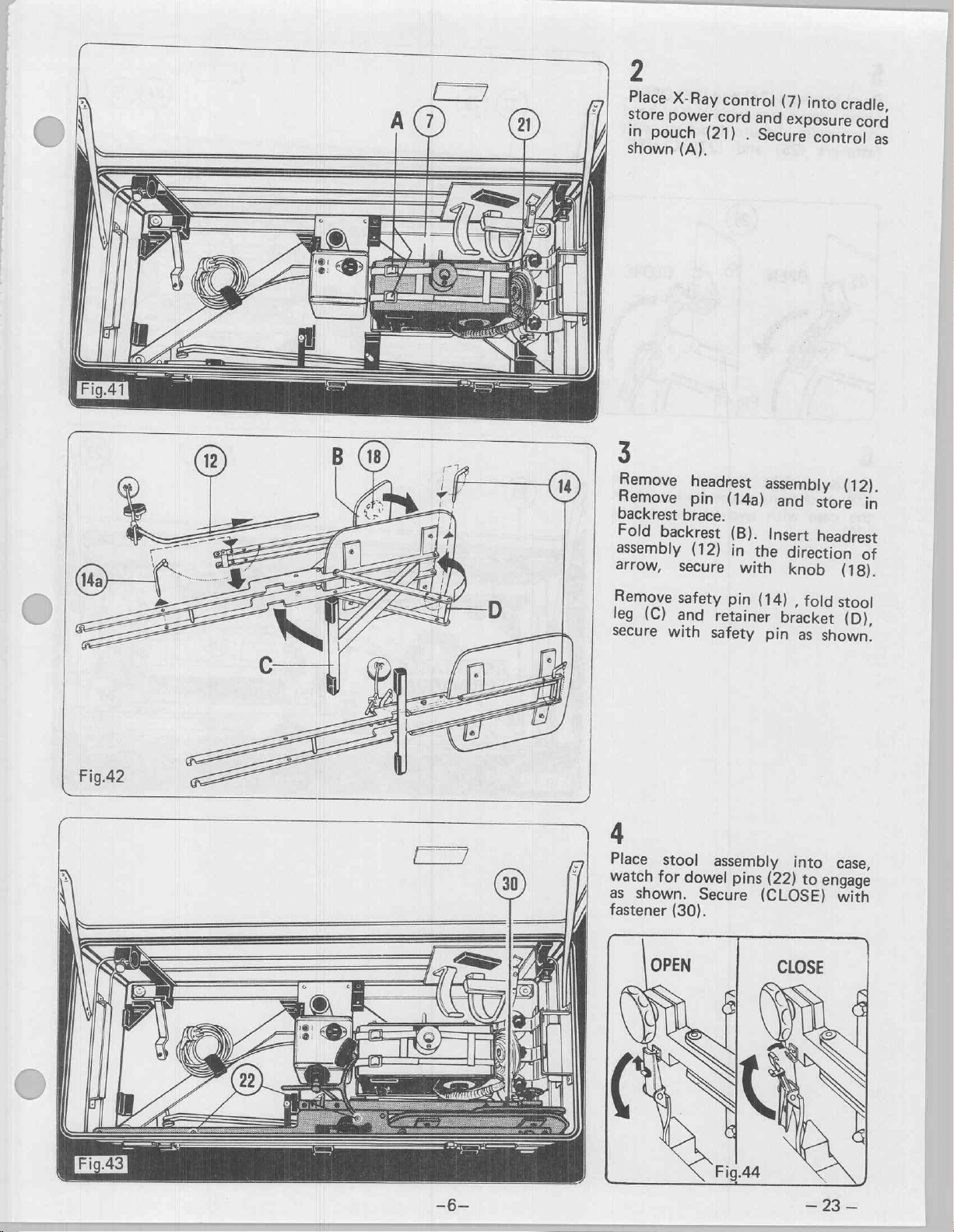
21
Place
store
in
pouch
shown
X-Ray
power
(A).
control
cord
(21)
and
.
Secure
(7)
into
exposure
control
cradle,
cord
as
3
Remove
Remove
backrest
Fold
assembly
arrow,
Remove
leg
secure
brace.
backrest
secure
safety
(C)
and
with
headrest
pin
(14a)
(B).
(12)
in
with
pin
retainer
safety
assembly
and
Insert
the
direction
knob
(14)
,
bracket
pin
as
4
Place
watch
as
fastener
stool
for
shown.
(30).
assembly
dowel
Secure
pins
into
(22)
(CLOSE)
(12).
store
headrest
(18).
fold
stool
(D),
shown.
case,
to
engage
with
in
of
Page 25
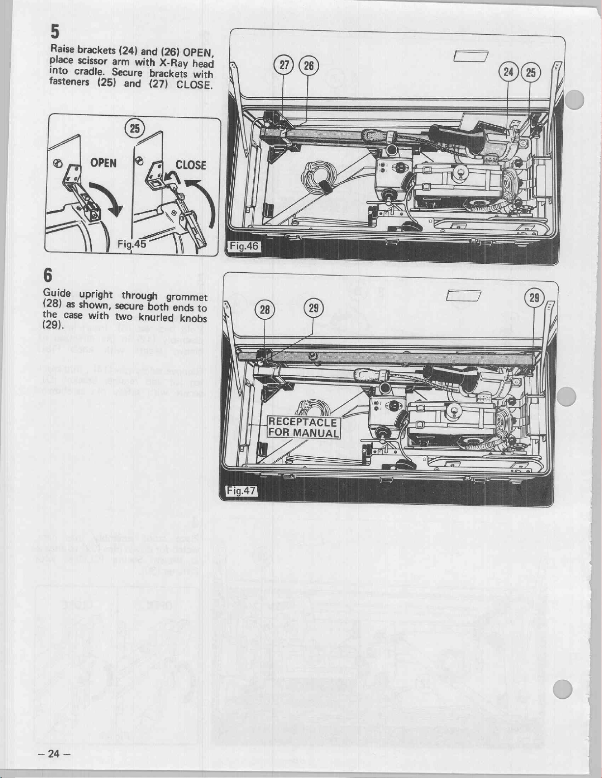
Raise
brackets
place
scissor
into
cradle.
fasteners
arm
Secure
(25)
(24)
with
and
and
(26)
X-Ray
brackets
(27)
OPEN,
head
with
CLOSE.
|
À
26
ES
VO
Guide
(28)
29).
upright
as
shown,
©
with
through
secure
two
knurled
grommet
both
ends
knobs
to
Fig.46
αλ
RECEPTACLE
FOR
MANUAL,
—
94
—
Page 26
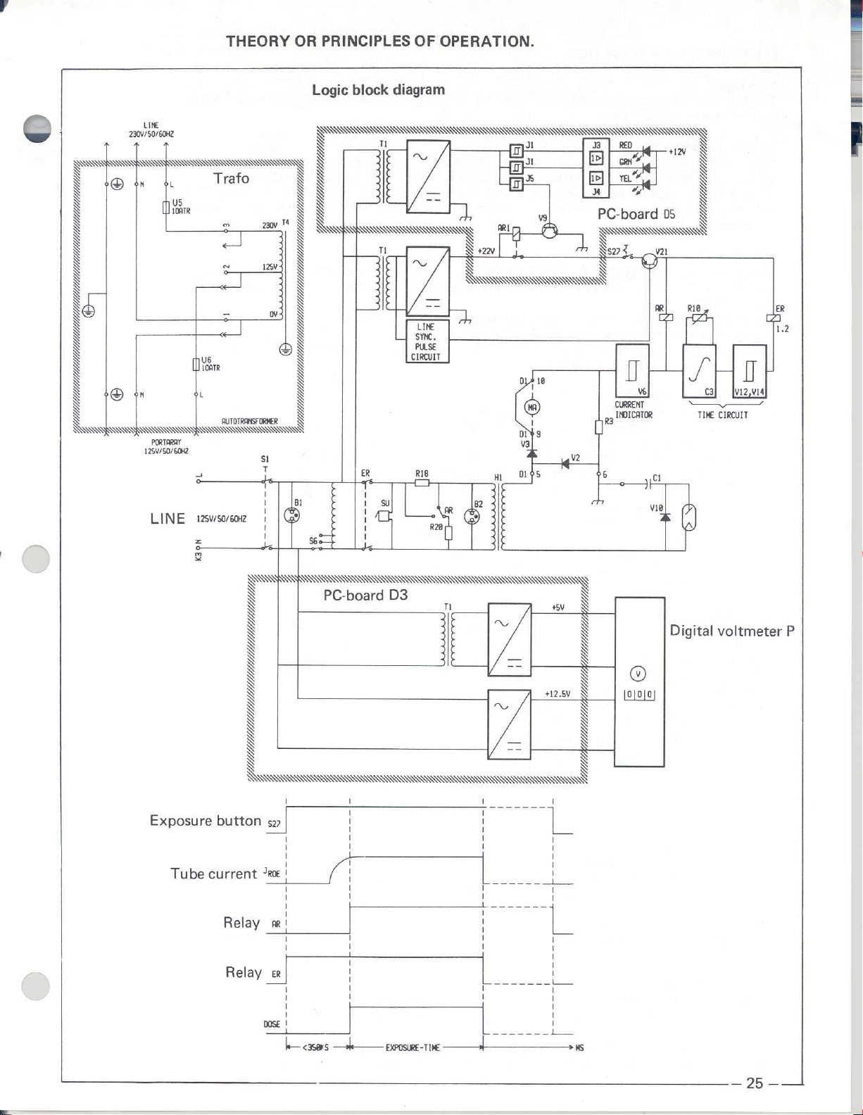
THEORY
OR
PRINCIPLES
OF
OPERATION.
VV
~
~
Y
sli
ae
1
|
©
di
©
è
PORTARAY
125V/50/60H2
LINE
SÌ
Trafo
—
vé
(Dicer
L
AUTOTRANSF
2
125v/50/6022
を
2
Logic
block
diagram
КА
А
T
5
N
NIN
NaN
T
SS
NS
XX
290.
À
KR
き
\
\
T
き
X
\
N
]
NW
S
き
À
N
き À
À き
き
き
N
À
à
N
き
き
S
À
T
N
SQ
S
き
à
き
き
à
À
N
N
\
ORMER
N
NS
S1
+
L
1
1
|
BI
|
1 1
1 1
Js
S6
PC-board
e
TE
Je
NN
1
1
1
1
n
ΤΙ
SU
ING
て
LINE
SYNC.
PULSE
CIRCUIT
me
=
—>
D3
ーー
À À
NE
/|
—
--
E
き
Ümmi
m
B2
R20
TI
Ty ' ee 7 °°
ma
Tm
了
ARI
a
NN
ο
區
~
АА
3
별
+12.5
+5V
<
А
3
|
mm
M
cil
πι
A
a
PC-board05
RSR
sor
Ÿ
S
\
À
X
N
并
JU
き
Li
~
V21
©
O)
ojojo
ii
S
\
À
V
き
き
Y
i
Mİ
RIS
ta
TH
o
τον
Digital
cs]
TIME
CIRCUIT
voltmeter
ER
Tİ
[avis
!
||
SS
1.2
P
—
ll
casas 一 和
|
一 一 fxp0suRE-Tike
жж
一
25 一 一
|
Page 27
DESCRIPTION
Line
input
The
line
if
input
the
switch
lights
OF
FUNCTION
is
protected
S
1
is
on.
with
the
fuses
U
2
and
U
3.
The
readiness
indicating
B
1
lamp
Control
The
control
voltage
Start
of
Depressing
cronized
energizes.
relay
The
relay
oltage
radiation
voltage
Since
base
the
The
drop
ing
exceeds
via
the
current
relays
emitter
in
it.
of
V
the
transformer
transformer
of
125
V
Exposure
exposure
to
the
power
contacts
through
the
indicator
dividers
capacitor
through
ER
1
and
current
It
is
12/V
thus
14,
value
the
of
in
the
line
button
supply.
ensures
place
the
voltage
B
2
are
R
31,
R
C
3
is
not
the
resistor
ER
2
energize.
of
V
14
possible
transistor
0.7
V
+
voltage
S
27
primary
divider
caused
32
controls
yet
flows
to
adjust
V
on
R
that
the
range
the.relays
The
schmitt
winding
R
18/R
to
operate
V
charged,
R
12/R
through
the
12
can
13.
Heliodent
of
109
ER
trigger
of
20.
At
and
20
and
the
transistor
14,
and
the
potentiometer
threshold
be
controlled
70
is
V
to
1
and
ER
(V
the
high-voltage
the
same
indicate
V
21
as
is
then
voltage
through
always
133
V
at
2
are
12,
V
14)
time
the
long
as
V
12
is
switched
R
of
the
only
operated
60
HZ,
controlled
switches
transformer
the
buzzer
duration
S
27
is
depressed.
blocked.
through.
13
and
once
causes
trigger
its
Schmitt
with
109
via
of
V
As
base
a
primary
V
to
V
21
and
the
H
1
SU
and
the
14
obtains
a
a
voltage
consist-
voltage
132
V
syn-
ER
under
the
X-ray
result,
Switching
As
У
through.
V
voltage
The
V
C
The
Converter
R
End
As
transistor
transistor
reduced;
V
Temperature
The
10°
Forced
In
switching
on.
If
over
—
26
—
soon
as
(У
4)
=
Then,
7
allows
of
collector
6,
and
keeps
2
serve
for
transistor
10
and
of
exposure
soon
as
on
12
is
controlled
R
11
to
70°
exposure
case
of
system.
no
tube
R
16
relay
AR
the
tube
2,4
Учи
the
the
AR
125
without
current
V
6
interference
V
7
and
provides
C
3.
The
C
3
is
V
12
switches
V
12
short
the
other
through
compensation
hot
wire
C
range.
a
defect
The
current
after
approximately
current
(V5)
transistor
relay
to
damping.
of
V
7
in
the
overmodulated
suppression.
also
controls
a
supply
exposure
charged
through.
circuits
hand,
even
compensates
where
no
capacitor
pulse
triggers
allows
=
0.7
V
7
draw.
flows,
the
voltage
times
to
the
the
base
the
faster.
tube
C
the
0,7
a
voltage
V
+
U
also
at
the
relay
(V
controlled
same
is
This
state
transistor
stabilized
of
0.066
threshold
This
initiates
section
voltage
drop
Thus,
the
temperature
current
7
is
charged
Dentotime,
to
1
sec.
drop
6)
places
time
(flip-flop
V
17.
to
3.2
voltage,
a
of
on
the
1
signal
through
and
the
on
the
=
0.7
V,
through
the
Heliodent
through
This
by
V
18
sec.
are
which
flip-flop
V
14,
so
R
13
ER
relays
resistor
the
function).
transistor
set
decreases,
R
3
which
transistor
R
9.
The
70
transformer
V
8,
R
8,
The
serves
to
the
integrator,
in
18
steps
a
| | i
is
adjusted
process.
that
the
On
current
so
drop.
V
6
collector
R
capacitor
as
with
the
that
-
response
- : -
triggers
the
the
resistor
of
the
entire
Dentotime
R
there
16
-
the
transistor
timer
V
circuit
6
is
controlled
is
actuated.
is
greater
is
controlled
current
5
to
the
an
impedance
consisting
R
10.
with
R
one
hand,
through
the
transistor
ele
circuit
is
a
after
switching
than
of
under
base
of
C
7
and
of
13,
the
the
ER
is
in
the
forced
through
a
Page 28

HZ
50/60
®
V
125
LINE
18A
MTR
®
je
1
1
|
|
1
1
i
i
181
1
1
|
1
1
1
ㅣ
|
i
|
ㅣ
I
da
B31
PN
È
と
109.44
|
oo
>
>
112.5V
LE
115.6V
È
>
118.8
121.9V
125.9
128.1V)€
jal
53.
e
31)
&
г
ga
2
N
<
一
Y
n
=
8
24
à
&
O
=
125v—
=
E
2160.16
V6,12,14,17,19,20..
V5,8,10,22,23.......
W,21
ТВ
VI
人
、B8eCise9
Фр
.BCYS8
e
siol]
©
k
KA
va
2.4V
R4
470
i
+
RI6
5.5
s
ai
anse
05.2.
(Page
_
05.1
_
DS.3
05.4
„BA
35)
(Раде
35}
(Page
35)
(Раде
35)
tube
e
current
jumper)
points
Measuring
for
(remove
|
Diva
3
오스
3
3
iow
01
i
cit
πιό
UG
|
QI
bri
16K
15916
527
a
р
И
ne
Di
ax
‘E
ul
©
I,
?
vz
|
Rol
las
ig
E
|
L
W
Re
*İC
IK
Ti
RI4
2.2K
RIS
2K
VIA
cs}
zer
Ra
Lie
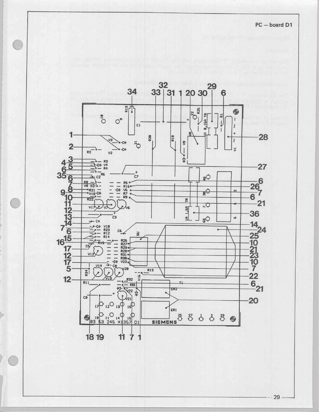
Page 29
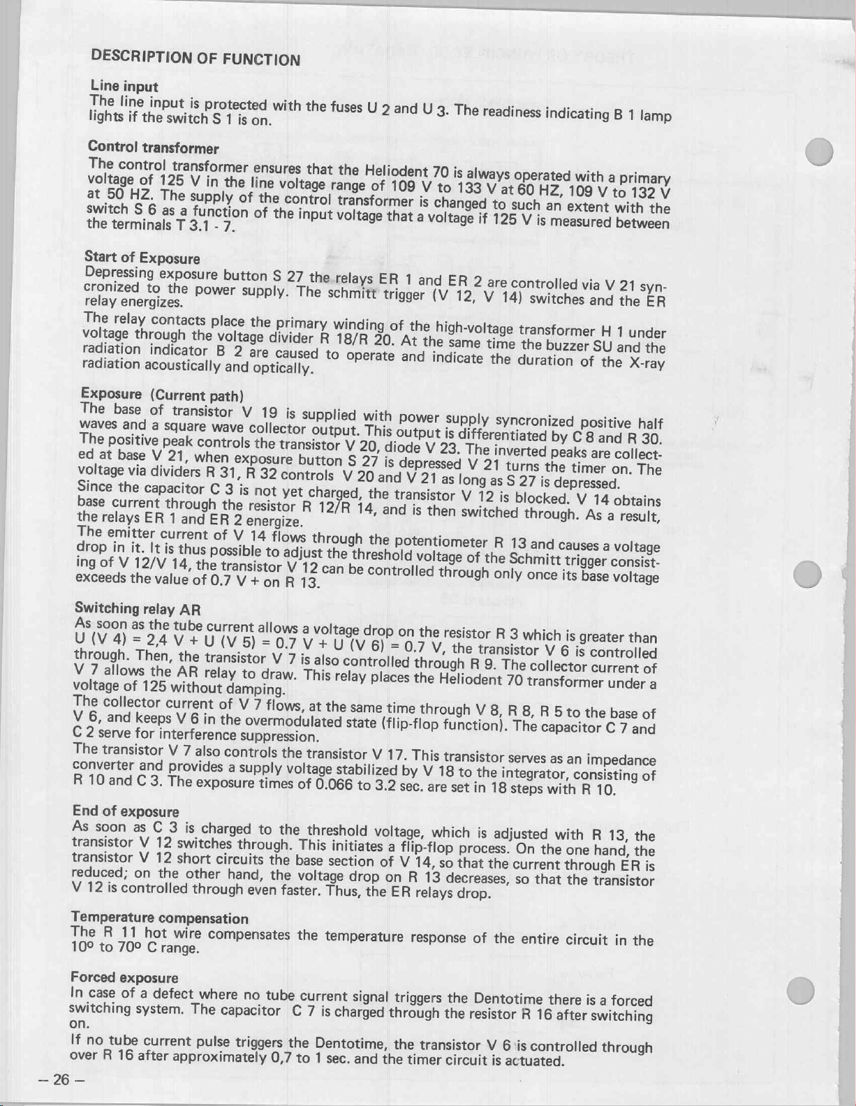
PC
—
board
>
SI-Diode
2
Zinkoxid
3
Metal
film
4
SI-Z-Diode
5
Metal
film
6
Carbon
7
SI-Planar-Diode
8
Metal
film
SI-Z-Diode
9
10
Metal
film
11
SI-PNP-Transistor
12
SI-NPN-Transistor
13
Capacitor
14
Ceramic
15
Metal
16
Metal
17
Ceramic
18
Measuring
19
Capacitor
20
Relay
21
Metal
22
Metal
23
Metal
24
Transformer
25
Relay
26
Resistor
27
Capacitor
28
SI-Rectifier
29
Fuse
30
Metal
31
Wire
32
Elko/Capacitor
33
Wire
34
Resistor
35
Ceramic
Fuse
36
Capacitor
film
film
Capacitor
N
film
film
film
N
film
wound
wound
spindel
Capacitor
D1
EGB
varistor
resistor
EGB
resistor
resistor
resistor
EGB
resistor
resistor
resistor
resistor
resistor
resistor
resistor
set
EGB
resistor
resistor
resistor
Adj.
EGB
EGB
EGB
V2, V3, V9,
R2
R3
Va
R4,
R34
R1,
R5,
V5,
V8,
R21
V18
R22,
R27,
V7,
V21
V6,V12,V14,V17,V19,V20
C3
C4,
C6
R12,
R14
R15,
R26
C5,
C8
R11
C9
AR,
ER1,
R9,
R28,
R19
R31
T1
SU
R16
C7
v1
U1
R25
R18
C1
R20
R13
C2
U4
R6,
V10
R30
ER2
R29,
V16
R7,
R33
R8
1000
V
1A
14
V
0,05W
510
Ohm
0,25W
BZX
97
C2V4
470
Ohm
0,25W
10k
0,25W
50
V
200
mA
390
Ohm
0,25W
ZPD12
100k
BCY78
BCY59
22MF
100NF
2,2k
22k
22NF
12
0,25W
IX
IX
TO-18
16
V-
100
0,25W
0,25W
100
V
1
2k5%0,1W
2,2MF
12
5,6k
5,6k
1k
125/17,
60
5,6M
4,7MF
B
0,16A
12k
6,8
1MF
82
100
330NF
1,5A
35
1U
V-
0,25W
0,5W
0,25W
5
1U
V-
0,25W
35
1A
V
80
250
0,5W
Ohm
V-
40
10W
Ohm
Ohm
100
V
250
V-
V23016
1
1%
V
V23016
V-
V
%
1
10W
+50
0,75W
V
slow
DO-41
1N
4007
069-X3011
1
%
Gr.
2,4
V
0,4W
1
%
Gr.
5
%
Gr.
0207
DO-35
V0,4W
1
%
TO-18
20%
V
10
1
%
%
Gr.
10
1
%
5
Gr.
32
45
0513
%
МБВ
Gr.
0207
0207
%
W5R
BAW
Gr.
%
DO-35
0207
V
200
V
200
7x5x4-2M
K11
20%
0408
0207
Gr.
1%
0309
Gr.
%
0207
Gr.
42
Typ
3VA
LO
0207
Gr.
%
1
Dry
0513
%
20
5x20
blow
slow
0309
Gr.
1045
Gr.
%
5
Gr.
%
-10
1045
Gr.
%
5
10
%
8x8x4-2M
WSR
%
10
1/4x1
blow
0207
5
%
DO-35
0207
76
0207
mA
mA
8x8x4-2M
mm
17x31
1/4”
κ
<
—
28
Page 30
17
一
2
asia
ЗбАЕ
[в
==
πα
E°
7
6
o
Bj
2
TO
12
>
=
_
一
一
ve
R2
VE
KFè-
а"
8
vz
——
一
—
/
一
Re
—
Ri6e—
и
ορ
Hf
ex
|
ーー
ca
ath
ua
?
120
0
poi
=
pe
13
=
1
1
=
2
1
©
一
a
È
y
a
Ng
4
al
Га
sasue
e
τι
ERZ
>
ERI
25
27
の
ららら
る
O
—
—e_R1
る
PC — board
Tel
vi
28
27
6
26
в’
a
dire
\
る
@|
264
ER
全
a
ri
21
|
'
00
D1
19
18
171
mogi
=]
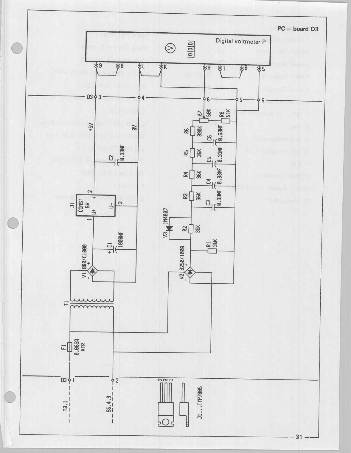
Page 31

Digital
Principle
The
Voltmeter
digital
portional
of
the
transformer
Line
voltage
The
transformer
voltage
the
respective
In
case
relay
of
AR
instrument
to
a
compensation
is
supplied
LED'S
an
over
1
energizes
“P”
PC
125
V
T
1
(D
T
1
(D
to
the
Red
voltage
interrupting
board D3
"P"
receives
line
voltage
3)
and
with
5)
supplies
Schmitt
(RT),
condition
input.
a
5
over
trigger
Green
the
a
rectified
The
VDC
circuit.
voltage
a
line
exposure
voltage
which
(GN),
the
Schmitt
exposure
filtered
power
in
Yellow
trigger
circuit.
12.5
V
supply
to
blocking
proportional
turn
controls
(GE).
J
5
output
measuring
the
instrument
voltage.
via
drives
This
gates
transistor
voltage,
consists
stabilized
J
3
and
pro-
J
VQ,
J
4
Page 32
19409
IC
o—
2
AS+
ζ
+
AS
+1
T
99917988|
ES
PC — board
Digital
]
MEE'6
I
=
€
-n
A
o
m
9
>
>
a
に
出
«9θύΝΙ
E
su
P
>
ace
|
№
|
ж
|
же
EI
99
30
#3
a
5;
066"
=
daa
voltmeter
P
D3
гар
440081
|
ТЕЛ
999!/9ZalZA
E
ЖЕ
十
%-
IA
I
4590°0
=>
πι
dlN
=
8
-
VEL
=
=
εν9ς
εεττ
E
O
=
=
SBBZdAL"
al"
"IC
—31——İ
Page 33

PC — board
1
Resistor
2
Metal
3
Metal
4
MKT-Capacitor
5
Metal
6
SI-Diode
7
SI-Full
8
Fuse
9
Ceramic
10
Volt.
11
Elko
12
Metal
13
SI-Full
14
Transformer
D3
spindel
film
resistor
film
resistor
film
resistor
EGB
wave
rectifier
Capacitor
Regulator
film
resistor
wave
rectifier
Adj.
EGB
EGB
EGB
R6
C3,
R2,
V3
v2
EF
C2
C1
R1
V1
T1
R7
R8
C4,
R3,
C5,
R4,
C6
R5
50k
51k
390k
0,33
36k
1000
B
250
0,063A
330NF
Typ
1000
36k
0,5W
80V
B
2x
115
0,75W
0,25W
0,5W
uF
250
0,25W
V
1A
V
0,7A
250
100
7805
uF
40
1A
V/2x
10%
1
%
1
%
V
-20
1%
DO-41
V
med.
V
10%
TO-220
V
+50
1
%
Gr.
6
V
Gr.
Gr.
Gr.
1N4007
5V/1A
-10%
0309
4VA
0207
0309
%
0207
sl.
W5R
18x15x9-6M
bl.
S10
5x10
8x8x4-2M
Gr.
17x31
TFB
468
mm
Page 34

Digital
na
©
voltmeter
P
58
6
25
©
K
ME
802
4
03152
3
03
cz
PC — board
>
D3
GB
GB
GB
B
M
334
Page 35

Linevoltage
The
15
switch
the
The
C
At
Via
(yellow)
As
controlled
The
the
As
J
The
diode
At
of
5.7
J
board
Schmitt
zener
4
smoothen
a
lower
the
the
control
light
light
the
control
1.1
controlled
output
V
a
control
J
5.1
from
inverter
diode
7
controlled
indication
V
stabilizer
D
1.
The
triggers
diodes
control voltage
lights
by
diode
of
(Green)
voltage,
to
L
V
the
signal
J
3
up.
voltage
R
11.
The
V
6
V
7
(Green)
voltage
via
R
J
3.12
is
deenergized
via
H.
J
and
and
over
voltage
J
2
receives
transformer
1
and
J
5.
3
and
V
4
increase
input
to
Schmitt,
the
Schmitt
the
AND
increases
output
is
deenergized
increases
10,
switches
changes
the
signal
lights
up
from
further
from
and
corresponding
R
12,
switches
exposure
its
input
T
1
trigger
gate
J
4,
output
of
the
J
3.12
(Nominal
H
L
to
light
diode
to
a
line
from
voltage
(D
5)
that
value
trigger
output
inverter
signal
inverter
in
turn
unit
(over
voltage
to
L.
H
and
V
voltage
H
to
interruption
from
the
supplies
J
of
via
the
R
1.2,
J
1.6
J
1.1
J
3.10
Schmitt
J
3.10
switches
-
changes
operating
condition)
J
3.15
changes
5
(Red)
lights
of
approx.
L,
thus
changing
PC
board
power
rectifier
C
circuit
and
J
and
J
signals
trigger
to
output
supply
V
R
5.2.
1.7
L,
the
J
from
D5
(signals)
1.7
from
condition).
the
output
from
H
up.
130
V,
the
the
output
of
1
the
8,
C
light
changes
L
to
to
output
the
voltage
3
and
are
diode
H.
H
to
signal
L.
The
signal
timing
for
R
5,
at
H.
V
6
to
L,
L
and
of
light
signal
of
Transistor
made.
be
can
V
9
conducts,
AR
1
energizes
thereby
interrupts
the
exposure.
No
exposure
Page 36

stě
#110
a
2
IE
MI
-—-
了
|
ay
91518
Lara
[Pet
4:
e
89°
GS
10
<
sa
deso
ze
DE
w
|
č
ЕЕ
E
O
|
|
=
ΖΙθέαλ!
*
"ес
|
|
|
=
|
|
91
—
yo
ASI+
|
|
|
E
E
€
刁
區
|
|
η
a
|
|
о
SET:
deren
=
er
8
A8
|
|
5°
5
8
a
ιο
4
8
618
29Z8
er’
218
이모
mb
AT
Ham]
301
|!
<
Sr
A
z
|»
ЗЕЕ"
€
n
NB
To
nez
NB
0!
=
ta
iF
2
*
15409
T
AZI
Mi
λθΙ
gly
「
「
1001
nez
z
L
LU
Ζ
ae
fai}
I
IC
」
A
ε
94
23008
3
a
y
E
ve
3
/
Ic
EC
3
“İş
—dsi}
El
<
a
3008
Г}
の
vi
ces
È
IA
MI
u
B
_
CEL
Vel
ΕΛ
So
YA
=.
2
sh
aa
e
+
sof
İmer
[eco
~
SA
==
Si
ea"
vat
44
MOI
na
Y
B
9
180bd4L"
m
"С
1
=
區
=
—
À
+
|
|
E
8
é
já
—
35
—
Page 37

PC — board
=
SI-Z-Diode
Carbon
Wu
W
Sl-npn-transistor
A
Double-OP-Amplifier
0
Capacitor
0D
Metal
3
SI-Diode
D5
resistor
film
EGB
SI-Z-Diode
O ©
Ga-As-P-Diode
=
o
Carbon
>
>
Ga-P-Diode
—
N
Capacitor
w
Ga-As-P-Diode
ER
B
Metal
Bk
一
q
Voltage
=
©
Resistor
=
M
Metal
>
©
Capacitor
=
©
Power
N
o
Capacitor
N
i
SI-Rectifier
resistor
film
resistor
regulator
spindel
film
resistor
inverter
EGB
resistor
EGB
EGB
EGB
EGB
Adj.
EGB
set
EGB
EGB
v8
R6,
R7,
vg
11,15
C3
R5,
R14,
v2
V3,
V4
V5
R8
V7
C2
V6
R1,
R2,
R3
12
R10, R11,
R4
C1
13
C4
VI
R13
R15,
R12
R18,
R19
ZPD5,6
820k
BCY
Typ
4,7
10k
50
V
ZPD8,2
5
mm
100
5
mm
22
uF
5
mm
470
7812
10k
100k
0,33
CMOS
2,2
uF
B80V
0,4W
59
1458
uF
35
0,5W
200
8,2
RM
Ohm
RM
25
yellow
Ohm
UC
0,75W
0,5W
uF
63
4049
40
1A
5,6
V
0,4W
5
%
VIII
TO-18
DIP
8pol.
V
20
1
%
Gr.
mA
DO-35
V
0,4W
2,5
red
0,2W
5
2,5
green
V
-20%
Typ
0,5W
1
TO-220
10%
1
%
Gr.
V
-20
B
DIP
V-
7x5x10
Gr.
%
7x5x10
0309
HLMP
%
0614
3400
%
Gr.
12
Lin
0309
%
Gr.
0309
5
Gr.
Typ
16
5
%
DO-35
45
V
200
(2x741c)
BAW
76
%
DO-35
0240
0204
3502
NASS
0309
V,
1A
liegend
06x19
mA
S
—
N
N
Flat
transformer
N
ω
AND-Gate
N
A
Relay
N
q
Ceramic-Capacitor
N
ο
Metal
film
N
N
Metal
film
36
—
4x2
EGB
resistor
resistor
TI
14
AR1
C5
R17
R16
127
C
MOS
12
V
0.33
120
4,7k
V/9,5
4081
-2U
uF
100
Ohm
0,5W
V
AU
V
0,5W
1%
1,8VA
B
DIP
LO
Monost.
10
1
%
Gr.
14
%
W5R
Gr.
0309
BV34
8x8x4-2M
0309
Page 38

PC — board
D5
Lar
Page 39

PORTARAY
Heliodent
70
Dentotime
Description
The
X-ray
voltage
temperature
Current
energizes,
relay
Accordingly,
As
soon
trigger
The
AR
The
tube
alternating
capacitor
with
D
1.9/D
are
exceeds
shorts
the
relay
the
diodes
1.10.
tube
switched
and
as
timer
current
current
charging
of
function
of
of
the
a
the
the
resistor
the
Heliodent
the
capacitor
drops
V
the
Heliodent
on
at
filament
given
timer
circuit,
circuit
only
as
cannot
flows
current
2
and
Hi
the
same
is
value,
R
18
is
then
C
3
shuts
the
be
measured
there
has
V
3.
70
is
time.
reached
the
Schmitt
consisting
and
separates
operated
is
charged
the
ER
trigger
been
(tube
short
The
switch
current
tube
JU
Tİ
Ci
indirectly
Thus,
tube
(after
150
trigger
of
C
the
from
to
the
relays
is
released.
directly
plus
circuited
current
Avi
heated,
current
to
250
(V
3/R
10,
resistor
the
line
threshold
down,
between
capacitor-charging
in
may
msec).
6)
V
without
and
the
be
i.
e.,
flows
As
switches
12,
V
R
20
voltage
the
the
points
tube
current
measured
A
the
heater
only
once
soon
over,
14
is
triggered.
from
the
damping.
set
exposure
X
current).
measuring
between
and
the
as
the
peak
the
power
on
the
is
terminated.
and
Y
Thus,
the
the
high
emission
tube
AR
relay
The
AR
source.
Schmitt
since
an
the
circuit
points
Heliodent
The
iM
V
10,
H
Tube
diode
70
1).
Trans-
Former.
voltage
Capacitor
voltage
voltage
voltage
circuit
Gi
<0
of
kV
the
os
—
Å
201 一 一 一 一
Heliodent
ZN
一
70
consists
if
a
voltage-doubling
,
DS
circuit
(C
1,
The
half
transformer
Page
negative
wave
of
half
the
transformer
peak
voltage
wave
of
the
is
measured
transformer
voltage
is
on
voltage
added
the
tube.
to
charges
the
capacitor
the
capacitor
voltage,
C
so
1.The
that
twice
t
positive
the
Page 40
MAINTENANCE
To
stay
in
It
is
the
respo
recommended
The
actual
viceman.
Instruments
maintenance
Neither
compliance
nsibility
maintenance
the
required:
with
the
of
the
user
schedule
inspection
inspection
DHHS
to
and
nor
requirements
insure
to
insure
that
consequent
service
is
the
the
equipment
compliance
service
part
of
the
PORTARAY
is
with
must
maintained
the
be
equipment
must
be
maintained
with
Federal
Performance
accomplished
warranty.
annually.
the
manufacturer's
Standard.
by
a
trained
ser-
Digital
Multimeter
equivalent.
Accuracy:
AC
DC
DC
voltage
voltage
current
+
+
+
0.5
0.1
0.3
Electromechanical
MODEL-
KESSLER
equivalent.
Regulating
Check
1.
Verify
Look
cracks,
2.
Operating
adequacy
Corrective
Defaced
Order
in
writing
transformer
as
follows:
that
for
test
Action:
labels
same
from
stating:
all
mechanical
the
LED
voltmeter
must
MODEL
%
of
reading
%
of
reading
%
of
reading
pulse
ELLIS
labels
tubehead
light
(yellow,
must
be
replaced.
SIEMENS
—
FLUKE
plus
plus
plus
counter
KT
(stepless)
are
affixed
damage,
90
possibly
in
all
working
green,
be
Operational.
MEDICAL
8000
1
digit
2
digits
1
digit
203
+
1
—
150
and
legible (labels
affecting
positions
red)
for
SYSTEMS,
A,
pulse,
VAC,
50
line
or
or
VA
see
page
radiation
for
possible
compensation
INC.
13)
safety,
Dental
(inspect
drift).
must
X-Ray
collimator
light
up
Division
for
Digital
line
(address
possible
see
rear)
Should
unit
mechanical
until
Defective
tion
LED.s,
as
to
the
above
applies.
WARNING!
CAUTION:
symbol
this
by
To
reduce
-ray
tube
be
just
Observe
3.
Check
4.
Make
sure
Customer
Customer
All
Model
legible
repairs
bulbs
operator,
or
for
Digital
Radiation
Radiation
personal
head,
long
the
enough
radiation
radiation
the
X-ray
Name
Address
Numbers
on
the
unit
damage
affecting radiation
replacements
power
line
therefore,
“on”
adeguacy
Safety
will
be
exposure
individual
to
permit
protection
warning
light
exposure
with
for
identification
correcting
light,
voltmeter
repairs
or
indicated
and
not
exposure
meter
as
outlined
and
acoustic
is
interrupted
Serial
Numbers
the
radiation
constitute
replacements
ДА
damage
times
readings.
in
on
buzzer
after
still
purposes.
safety
be
defect
indicating
must
the
shall
page
12.
for
releasing
evident,
are
made.
light,
a
safety
be
proper
the
user
inoperative
hazard
made
to
promtly,
functioning,
the
exposure
is
not
the
patients
same
switch
permitted
line
compensa-
rule
(dead
well
as
man
to
use the
featu
re).
39
一
一
Page 41

Electrical
Measurement
/
Calibration
Checking
(Power
Remove
Set
8.0).
N,L.
Turn
value.
The
A.C.,
*
Line
the
supply)
cover
the
multimeter
Connect
on
the
measured
and
may
voltage
line
voltage
.CAUTION
the
power
line
not
range
to
test
supply,
voltage
exceed
at
50
WIRES!
a.c.
leads
must
133
HZ
voltage
to
the
note
be
V,
a.c.
ONLY
(range:
terminals
the
measured
at
least
132
V
150V,
K3
109V,
Remove
remove
screws
housing
to
cover
Loosen
remove
Fig.48
screws
cover
to
Digital
minus
Plug
Turn
(warm-up-time).
Compare
the
indicatea
curacy
WARNING:
Electric
For
to
line
1
power
in
on
digital
tolerance.
reasons
the
various
adequacy
digit
the
X-Ray
the
line
must
shock
of
accuracy).
supply.
indicated
hazard!
test
test
control,
adequacy
be
within
safety,
points
instrument
value
test
your
always
during
“P”
wait
5
min
on
the
multimeter
instrument.
multimeters
disconnect
the
calibration.
(plus,
The
stated
the
powercord
with
values
ac-
SIEMENS
109 - 133%
Fig.49
while
the
Housing
cover
measu
ring
leads
are
connected
—
40
—
Page 42

Verification
Determine
indicated
on
of
that
the
the
line
the
power
digital
voltage
supply
panel
voltmeter
compensation
is
within
the
VEE
light
specified
ine
diodes
range
voltage
(LED)
of
range
function.
109
VAC
at
50
HZ
to
133
ONLY
VAC
132
max.
y
Dependent
Corresponding
On
Digitalinstrument
hand
109
nov
111V
112V
113V
114V
115
y
116
У
17V
118V
119V
120V
121V
122
V
123
y
124
y
125V
126
У
127
V
128
V
129
V
130
V
131V
132V
133 V sk
of
V
on
Chart
o
m
o
m
o
m
©
m
o
m
o
m
o
m
o
m
o
m
ιο]
[πι]
[πι
[πι
[πι
[πι
[πι
[πι
ΣΙ
the
line
LED's
A
compare:
Switch
3
GE
GE
GE
GN
GN/RT|
GN
GN
GN/RT | RT
RT
RT
RT
voltage
Yellow,
S6
3
GE
GE
GE
GN
GN
GN
RT
RT
POSITION
4
GE
GE
GE
GN
GN
GN
RT
RT
RT
indicated
Green
5
or
sis
O:
1
Red
8
6
and
position
light
6
7
7
GE
GE
GE/GN
GN/|
GN
RT
GN
RT
GN/RT
RT
RT
RT
RT
RT
RT
RT
RT
RT
RT
RT
RT
RT
RT
RT
RT
RT
RT
RT
RT
RT
RT
RT
up.
8
GN
GN
of
line
Compensation
Legend
GE = yellow
N = green
RT = red
Chart
S6
Positions
A
switch
S6,
the
Note:
A
the
one
position
actual
iti
line
shift
i i
of
voltage
the
lies
LED
in
between
display
the
in
in
re
relation
voltage
to
values
the
switch
shown
position
the
on
S6
chart.
can
occur
if
die
Page 43

Example:
Indicated
Instrument
Verify
With
(see
linecompensation
Verify
measuring
P
(see
load).
(no
Set the
button.
on
the
Make
line
voltage
“P”
一
power
the
figure
figure
object/time
an
supply
multimeter
48).
that
the
instrument
49).
exposure
To
3,2
s
exposure
—
position
4
3
2
1
8
adequacy
connected
AC
input,
adjusted,green
voltage
coincides
Note
time
indicated
selector.
p
indicated
the
by
rotating
by
unit
with
value
of
S6
5
6
7
to
turned
LED
instrument
the
the
orange
—
LED
lit
K3
N,L
lit.
on,
on
your
indicated
object
line
1to3
4
5
10
6
7
Yellow
Green
Green
Red
or
Red
G
Y
οοο
R
Observe
To
calculate
voltage.
NO
LOAD
The
maximum
In
the
event,
Tube
current
Remove
the
the
voltage
the
power
VOLTAGE
permissible
that
the
9—10
iumper
reading
supply
power
from
(under
VOLTAGE
is
load)
adequacy,
VOLTAGE
insufficient
Circuit
enter
DROP
an
Board
below
UNDER
must
adeguate
D
1.
the
LOAD
not
power
measured
exceed
6,0
supply
values,
VOLTAGE
Vin
the
must
be
starting
DROP
exposure
found.
with
the
range
no
given.
load
—42—
Page 44

Me
TT
Connect
Select
Set
Make
The
Note
The
+1,0
The
released
Disconnect
Reinstall
DCmA
2,0
an
buzzer
the
reading
ОСтА
exposure
(deadman
the
the
multimeter
range
sec.
on
the
exposure.
must
mA
value
should
—2,5
must
the
instrument.
jumper
(10
time
è
sound
and
on
the
be
7
DCmA
ОСтА
be
terminated
feature).
9
-
10
to
D
1.9
DCmA).
selector
the
red
instrument.
(tolerance
50
HZ)
at
on
circuit
-
10
Li
(m
し
Fig.53
radiation
+
1,2
once
if
the
board
D1.
light
on
DCMA
exposure
the
front
—
2
button
panel
DCMA
10
must
60
HZ
is
prematurely
light
/
up.
Exposure
The
The
time
exposure
counter
time
must
is
connected
be
checked
as
described
with
below.
a
mechanical
counter
D14
D1.21
Test
or
eguivalent.
point
|
OJO
Pulse
counter
aş
Page 45

Set
the
exposure
time
as
shown
in
the
table
below.
Make
an
Note
the
Caution:
Observe
Relative
For
the
power
example,
exposure
pulses
cooling
duration:
3,2
sec.
on
Exposure
0.066
3,2
è
the
time
between
exposure
A
pulse
1
:
60
time
sec.
sec.
counter
exposures.
/
min.
time
—
used.
cooling
a
pause
Pulses
_|50HZ!60HZ|
|
Susi
160
period
of
3
1/2
|
|
20
min.
4
192
sec.
Tolerance
+
-
|
+
-
1
2
10
20
pulse
Bons:
pulses
pulses
If
the
measured
the
data
Make
an
With
potentiometer
is
obtained,
©
=
Increase
©
=
Decrease
pulse
as
indicated,
exposure.
the
the
count
adjust
p
R13
on
exposure
exposure
does
as
the
time
time
not
agree
follows:
circuit
board
with
D1,
adjust
the
value
until
the
proper
pulse
count
Page 46

Mechanical
1.
Spring
Adjustment
The
spring
after
installation
The
two
is
in
a
is
accessible
increases
adjustments
adjustment
Possibility
counter
spring
vertical
with
the
spring
poise
at
the
adjustment
position
a
medium
tension.
and
(if
required)
of
the
spring
is
set
at
the
customer’s
screws
after
removal
size
screwdriver
Finally
counter
factory.
facilities.
(c,d)
are
of
tighten
poise.
However,
Loosen
accessible
the
held
screws
caps
in
vertical
(a)
screws
(b).
again.
at
it is
the
possible
(a)
by
double
One
of
position.
to
turning
joint
the
screws
Clockwise
make
readjustments
(1
1/2
when
heads
turns
the
folded
is
lower
movement
max.).
arm
but
Fig.58
2.
Friction
The
adjustment
of
arm
to
the
X-ray
scissor
shall
When
45°)
by
is
remain
the
itself
made
arm.
lowering
X-ray
with
pad
sequence
be
adjusted
head
in a 450angle
The
stationary
the
head
when
screw
released.
(d).
arm
X-ray
must
is:
(1
1/2
with
at a 45°
head
return
Spring
loosen
turns).
to
the
the
X-ray
angle
(to
to
screw
as
459
adjustment
(a)
Position
vertical
head
shown.
less
than
angle
Fig.59
When
450)
itself
made
raising
the
X-ray
when
with
screw
the
X-ray
head
released.
(c).
head
must
Spring
(to
more
return
adjustment
than
again
by
is
Page 47

Tube
head
rotational
stop
Test
540°
the
(1
tube
1/2
head
turns).
rotation
from
stop
to
sto
for
i
Fig.61
To
inspect,
Safety
remove
Secure
with
tape
strap
Countersunk
|
540°
X-ray
head
screw
from
\
be,
scissor
Secure
with
|
O
a
—
arm
tape
as
follows:
Rotational
To
facilitate
Scissor
as
arm
shown.
parts
the
must
may
reguire
removal
be
secured
replacement.
of
the
X-ray
with
the
head,
safety
the
strap
U-channel
sul
ey
Remove
Disconnect
CAUTION:
The
X-ray
Scissor
Remove
Remove
Hold
(22).
cap
wires
tube
arm
cover
countersunk
X-ray
Remove
and
cover.
wires
in
must
be
assembly
wires
(23).
head
X-ray
the
U-channel
marked
wires | 3 | 4 | 5 | 6
at
as
| 3 | 4 | 5 |
screw
the
yoke
head.
and
follows:
from
and
bracket
remove
ground
wire
O,
6
(22).
bracket
DAT
—
Page 48
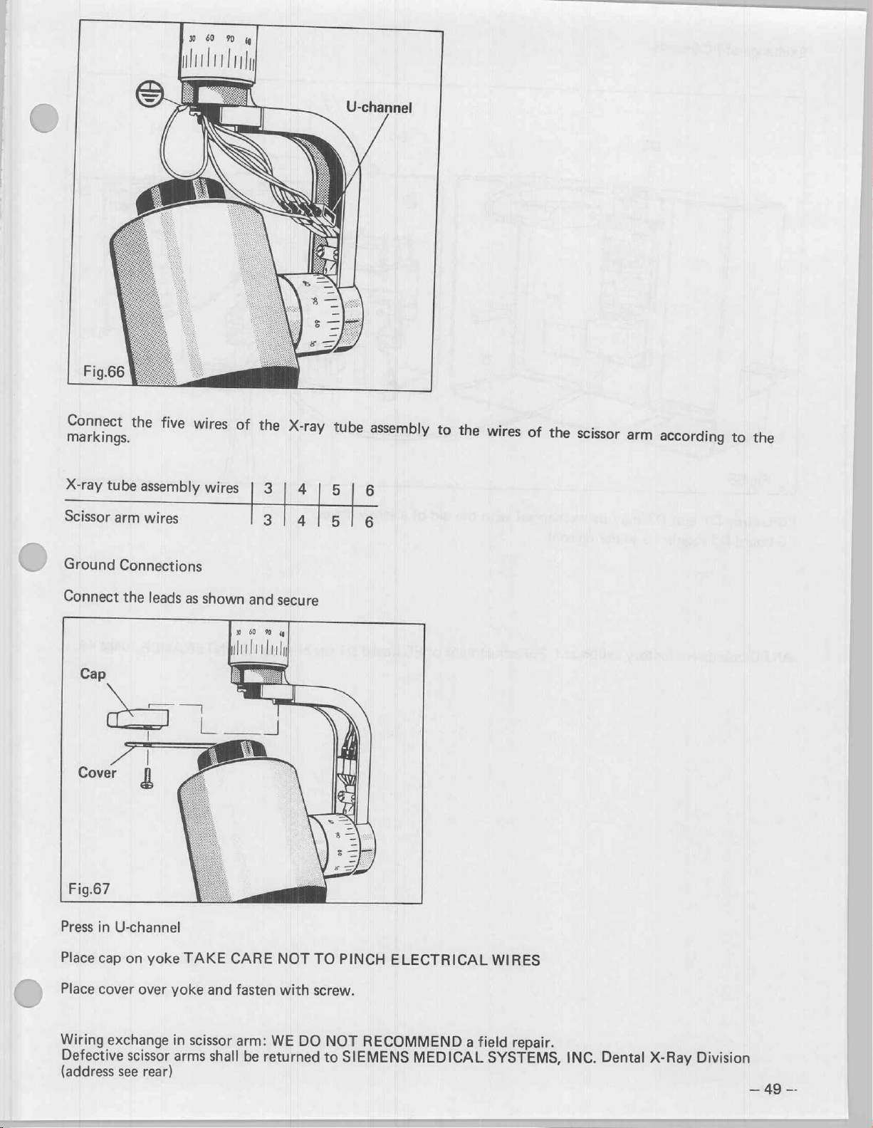
Connect
markings.
X-ray
Scissor
the
tube
arm
five
wires
assembly
wires
wires
of
|
|
the
e
3
3
X-
X-ray
|
4
|
|
4
|
U-channel
tube
assembly
5
|
6
5
|
6
to
. . 5
the
wires
of
the
scissor
arm
according
to
the
Ground
Connect
Connections
Press
in
U-channel
Place
cap
the
on
leads
yoke
as
shown
TAKE
and
CARE
secure
NOT
TO
PINCH
ELECTRICAL
WIRES
Place
cover
Wiring
Defective
(address
exchange
see
over
yoke
scissor
rear)
in
scissor
arms
and
fasten
arm:
shall
WE
returned
be
with
DO
screw.
NOT
SIEMENS
to
RECOMMEND
MEDICAL
a
field
repair.
SYSTEMS,
INC.
Dental
X-Ray
=
Division
49
Page 49

Connect
markings.
X-ray
Scissor
the
tube
arm
five
wires
assembly
wires
wires | 3 | 4 | 5
of
the
X-ray
| 3 | 4 | 5 |
U-channel
tube
assembly
|
6
6
to
the
wires
of
the
scissor
arm
according
to
the
Ground
Connect
Connections
the
Press
in
U-channel
Place
cap
on
leads
yoke
as
shown
TAKE
and
CARE
secure
NOT
TO
PINCH
ELECTRICAL
WIRES
Place
cover
Wiring
Defective
(address
over
exchange
scissor
see
rear)
yoke
in
scissor
arms
and
fasten
arm:
shall be
with
screw.
WE
DO
returned
NOT
to
SIEMENS
RECOMMEND
MEDICAL
a
field
repair.
SYSTEMS,
INC.
Dental
X-Ray
Division
=49/
一
Page 50
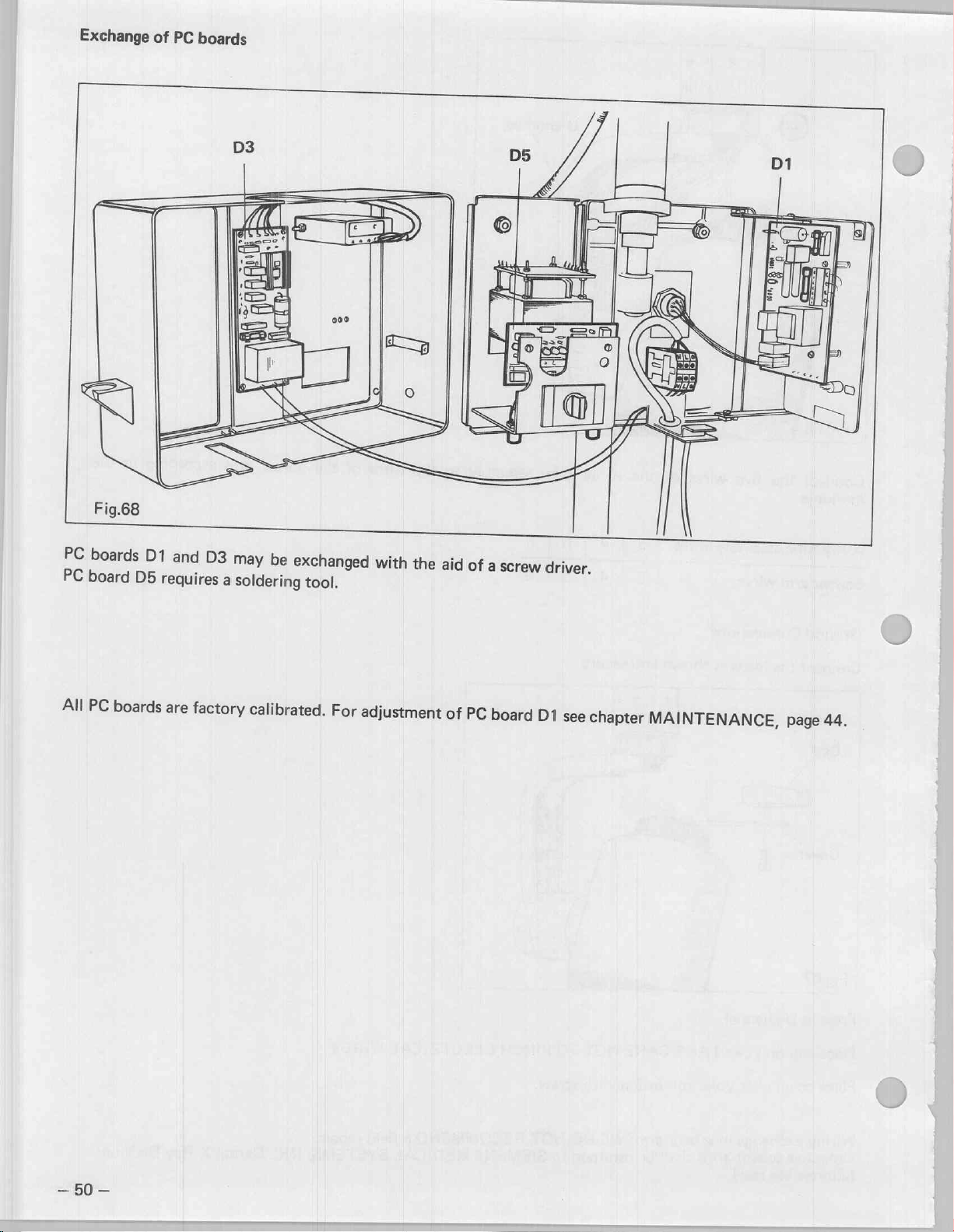
Exchange
of
PC
boards
B
IL
|
Fig.68
PC
PC
All
boards
board
PC
D1
D5
boards
requires
are
and
D3
factory
ah
may
be
a
soldering
calibrated.
exchanged
tool.
For
/
with
the
aid
adjustment
of
of
PC
a
screw
board
driver.
D1
see
chapter
MAINTENANCE,
page
44.
=50—
Page 51

No
X-ray
Г
X-rays
output
emitted
can
from
be
checked
tube head
with
—
blank
a
fluorescent
radiographs
screen,
if
available.
=)
Fluorescent
screen
Place
table
Place
order
Set
Make
During
will
screen.
At
indication
must
dible
y
the
counter
or
a
coat
to
dim
exposure
an
exposure
=P
the
be
visible
the
same
lamp
light
sound
fluorescent
as
top
over
the
the
surrounding
1,0
time
OL
”
exposure
on
the
time,
the
at
theDENTOTIME
up,
simultaneously
is
present.
screen
shown.
X-ray
sec.
head
the
radiation
fluorescent
red
radiation
on
a
in
area.
au-
η
し
Fig.70
If
no
as
follows.
X-rays
are
present
but
all
visual
and
audible
indicators
are
functional,
N
'
make
를
「
=>
レコ
レコ
electrical
measurement
See
Page 52

Electrical
Remove
Connect
(X-ray
U
and
Select
Make
cover
multimeter
head
V).
range
an
exposure
=“
ww
measurement
and
aluminum
at
terminals
150
VAC.
EN
disc.
leadsSand
are
marked
4.
If
a
voltage
of
approx.
120
Range
V
is
Present,
150
VAC
the
X-ray
head
is
defective
)
and
must
be
exchanged.
—
52
—
Page 53

STORAGE
INSPECTION
PROCEDURE
SERIAL
First
inspection:
Further
UNIT's
Date
of
Month
inspections:
SERIAL
inspection
Day
18
NO.
months
every
Year
after
12
months
date
of
manufacture
thereafter
Inspectors
name
Signature
NO.
10
ra
Page 54

ASSEMBLY
INSTRUCTIONS
FOR
PORTARAY
-
MODEL
D
3152
After
the
completed
assembly
the
carrying
case
must
be
leveled.
Page 55

Set-up
1
Remove
ing
Lay
bers
all
(1).
case
out
components
sequence.
in
components
from
carry-
keeping
num-
Insert
bracket
arrow.
Lift
a
upright
support
in
6).
(3)
in
bars
upright
(2)
into
the
direction
(4)
and
as
shown
base,
(5),
with
swing
of
the
secure
knob
2
Engage
trol
adapter
with
knob
dowel
(8).
pins
(7)
of
in
upright,
X-Ray
—55—
con-
secure
Page 56

3
Loosen
a6”
opening
before
as
pling
safety
of
engaging
shown.
strap
the
scissor
the
arm
(9)
to
in
arm
the
permit
(10)
cou-
CAUTION!
Opening
Scissor
arm
damage.
safety
arm
Connect
with
strap
is
fully
lock
To
of
arm,
DO
completely,
engaged
multi
ring
in
prevent
the
spring
causing
NOT
in
pin
plug
direction
accidental
loaded
injury
REMOVE
unless
the
coupling.
(11)
secure
of
arrow.
and
the
CAUTION
ΠΠ
"eb
”
4
Loosen
assembly
Remove
stool
leg
(15).
With
secure
shown
see
knob
(12)
safety
(13)
stool
same
detail.
(18),
from
pin
and
leg
with
remove
storage
(14).
retainer
fully
extended
safety
headrest
position.
Unfold
bracket
pin
as
Page 57

] 5
Engage
cure
rest
Position
brace
with
Insert
cure
height
Adjust
with
When
Connect
into
When
Connect
former's
the
the
stool
support
with
knob
in
direction
backrest
(17)
(3
safety
knob
the
transformer’s
230 V wall
pin
headrest
with
the
the
knob
adjustment).
headrest
(19).
power
the
115 V wall
power
the
power
115 V outlet
in
upright,
(16).
Raise
of
arrow.
with
positions)
(14a).
assémbly
supply
power
supply
cord
power
outlet.
and
(18)
cradle
is
cord
outlet.
is
at
and
se-
back-
backrest
secure
(12),
se-
(headrest
position
115
V:
directly
230
V:
the
trans-
connect
cord
into
TRANSFORMER
OUTLET
115V
In
case
diesel
rator
technical
Power
Volts:
Max.permissible
253
VAC
Max.
line
voltage
1.5 % at
of
driven
must
rating: 5 kVA,
230 V nominal,
permissible
meet
characteristics:
during
230
VAC.
6
Level
ča,
The
lower
the
0).
leveling
carrying
carrying
aid
of
devices
case
aportable
generator
the
deviation:
fluctuation
standby:
case
and
3-leveling
hook
frame.
gasoline-
this
following
single
207
upright
devices
to
gene-
phase
to
of
the
—
57
—
Page 58
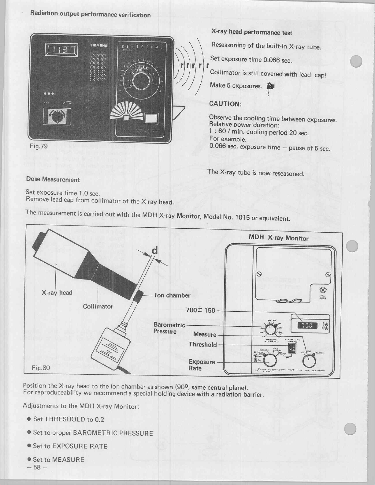
E
Radiation
1
Fig.79
Dose
output
Measurement
performance
2200
999
eee
verification
=
eee
ret
X-ray
\
Reseasoning
Set
Collimator
Make
CAUTION:
Observe
Relative
1
:
60
For
0.066
The
head
exposure
.
5
/
example,
sec.
X-ray
performance
of
the
time
is
still
exposures.
the
cooling
power
min.
duration:
cooling
exposure
tube
is
built-in
0.066
covered
p
time
period
time
now
reseasoned.
test
X-ray
sec.
with
lead
between
20
sec.
一
pause
tube.
cap!
exposures.
of
5
sec.
y
E
Set
exposure
Remove
The
Fig.80
Position
For
lead
measurement
X-ray
the
reproduceability
time
cap
head
X-ray
1.0
sec.
from
collimator
is
carried
Collimator
head
to
we
recommend
of
the
X-ray
head.
out
with
the
MDH
X-ray
Monitor,
lon
chamber
700+
Threshold
Exposure
nee
(90°,
device
Measure
same
with
the
ion
chamber
a
special
Barometric
Pressure
as
shown
holding
Model
150
central
a
radiation
No.
1015
MDH
plane).
barrier.
or
equivalent.
X-ray
-
Monitor
Adjustments
@
Set
THRESHOLD
©
Set
to
proper
©
Set
to
EXPOSURE
©
Set
to
—
58
MEASURE
一
to
the
BAROMETRIC
MDH
to
0.2
RATE
X-ray
Monitor:
PRESSURE
|
-=
Page 59

Make
an
exposure
The
measured
For
reproduceability
In
the
event
dose
the
should
dose
be
note
the
levels
700
distance
are
lower
mR
plus
than
WARNING:
RADIATION!
minus
,
where
specified
150
the
mR.
measured
above,
the
dose
X-ray
value
head
is
obtained.
needs
to
Distance
be
replaced.
d:
Note
the
values:
1.
Di
É
ses
ο...
Total
If
the
average
pulses
pulses
pulse
and
pulse
=
la
divide
count
by
4 =
average
is
not
=
pulse
within:
count.
1
to
2
to
4
pulses
5
pulses
Checking
Pulse
203
Connect
Set
Make
CAUTION:
posures.
Relative
1
:
60
For
0.066
3.2
sec.
the
counter
+
1
pulse.
pulse
exposure
four
exposures
power
/
min.,
example:
sec.
exposure
exposure
exposure
Model
counter
time
Observe
duration:
cooling
ATTENTION!
Measurements
recorded
at
50
Hz
at
60
Hz
followed
on
the
see
MAINTENANCE,
time
-
KESSLER
as
0.066
shown.
sec.
ELLIS
KT
>
the
time
time
cooling
period
—
—
pause
20
sec.
pause
of
time
of
5
3
1/2
between
sec.
min.
Installer/Assembler
by
this
OA
(nata
ler
symbol
Check-
page
must
44.
ex-
be
list!
Set
exposure
Make
Note
1.
2:
3.
4
Total
If
the
four
exposures
the
values:
LL
ae
average
pi
time
pulses
usas
pulses
ulses
and
pulse
3.2
sec.
δν
divide
count
um
by
4
average
is
not
=
pulse
within:
count.
140
to
172
to
ATTENTION!
Measurements
recorded
170
pulses
202
pulses
at
50 Hz
at60
on
Installer/Assembler
followed
the
OA
Hz
see
by
this
Installer
MAINTENANCE,
symbol
Check-
page
must
44.
be
list!
—
59
—
Page 60

Inspection
№
а
mechanical
etc.)
is
visible,
changed.
Remove
gasket
remove
to
Apply
turers
(Adhesive
Install
old
retainer
new
instruction.
new
of
the
the
gasket
groove
adhesive.
old
adhesive
part
no.29
gasket.
gasket
defect
gasket
and
with
78
(cuts,
must
clean
per
manufac-
195
frayed
be
a
scraper
D
3152).
ex-
the
Fig.83
60
—
Desiccant
(Branogel).
The
changed
The
packaging
color
color
bag
desiccant
every
desiccant
has a color
blue
means
pink
means
bag
year.
bag
“good”,
“not
must
in
indicator:
the
good”.
be
storage
ex-
Page 61

Repacking
Disconnect
unit
1
Remove
first!!
Place
as
shown.
X-Ray
safety
strap
from
Arm
over
power
assembly
scissor
supply
(10)
arm
CAUTION
CAUTION!
Procedure
damage
is
Loosen
multi
sor
shown,
over
greenfield
spring
pin
arm
multi
to
loaded).
locking
connector,
assembly
place
tubing
Failure
may
cause
the
scissor
ring,
from
protective
pin
connector
tighten
to
follow
injury,
arm
(the
disconnect
disengage
coupling
sleeve
(11),route
strap
this
and/or
arm
scis-
as
(23)
(9).
し
Fig.84
Remove
Fold
cure
with
tion
of
Store
shown
all
support
bracket
arrow.
leveling
and
secure.
other
bars
(4)
(3)
brackets
components.
and
(5),
se-
in
the
direc-
(20)
as
Page 62
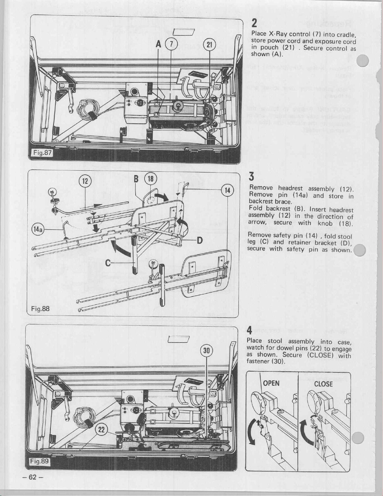
7
21
2
Place
store
in
pouch
shown
X-Ray
power
(A).
control
cord
(21)
and
.
Secure
(7)
into
exposure
control
cradle,
cord
as
3
Remove
Remove
backrest
Fold
backrest
assembly
arrow,
Remove
leg
(C)
secure
4
Place
watch
as
fastener
stool
for
shown.
headrest
pin
brace.
(12)
secure
safety
and
with
dowel
Secure
(30).
assembly
(14a)
(B).
in
the
with
pin
(14)
retainer
safety
assembly
pin
pins
(CLOSE)
and
Insert
direction
knob
,
fold
bracket
as
into
(22)
to
(12).
store
headrest
in
of
(18).
stool
(D),
shown.
case,
engage
with
Page 63
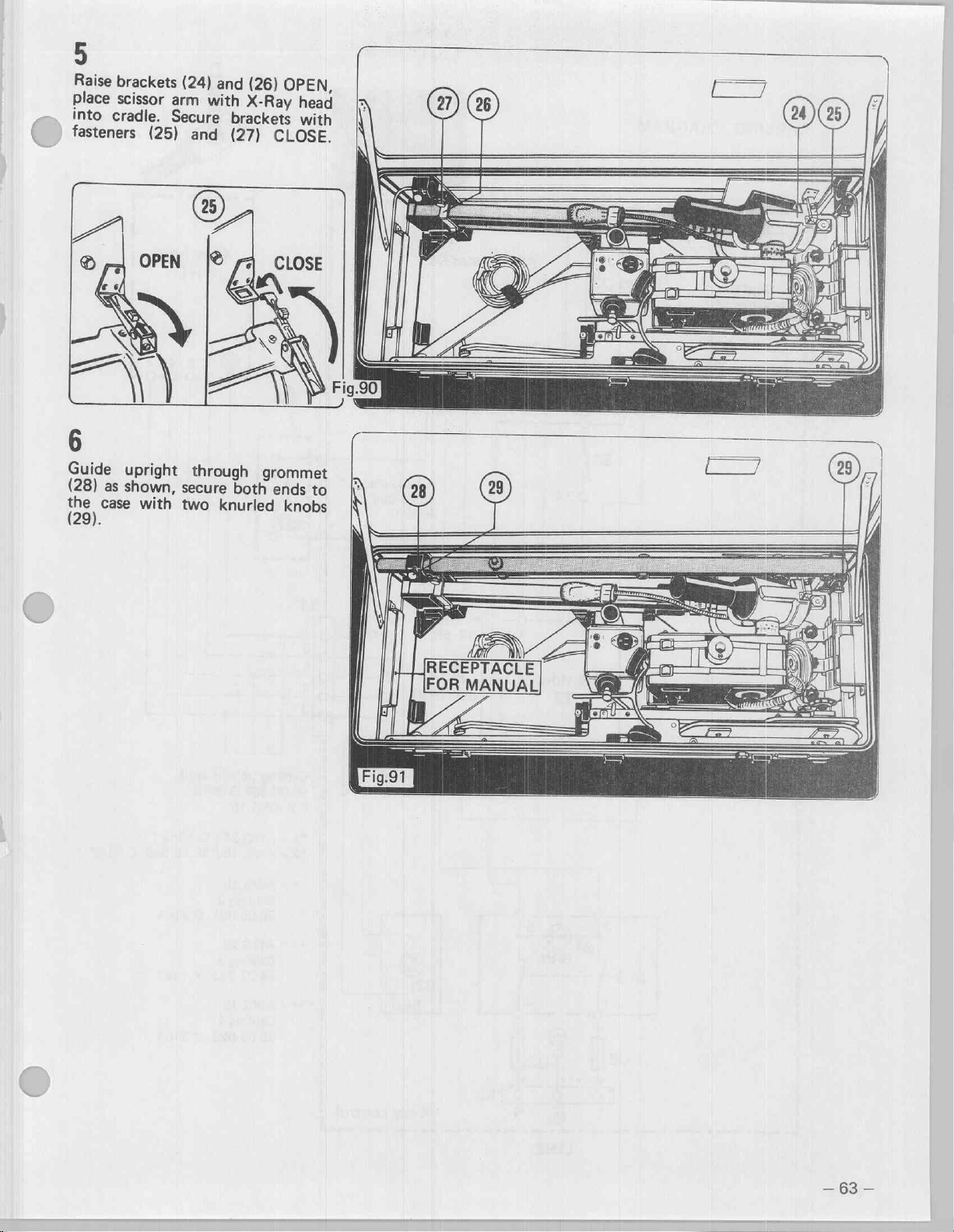
5
Raise
brackets
place
scissor
into
cradle.
fasteners
arm
Secure
(25)
(24)
and
with
brackets
and
(27)
(26)
OPEN,
X-Ray
CLOSE.
head
with
y
ト
©
(r,
Guide
(28)
the
case
(29).
upright
as
shown,
with
through
secure
two
knurled
grommet
both
ends
knobs
to
|
Fig.91
RECEPTACLE]
FOR
TA
MANUAL
ㅣ
(을
“o
|
©
2
A
E
OFT
SA
29
ts
0
EN
N
a
|
|
-
63
—
Page 64
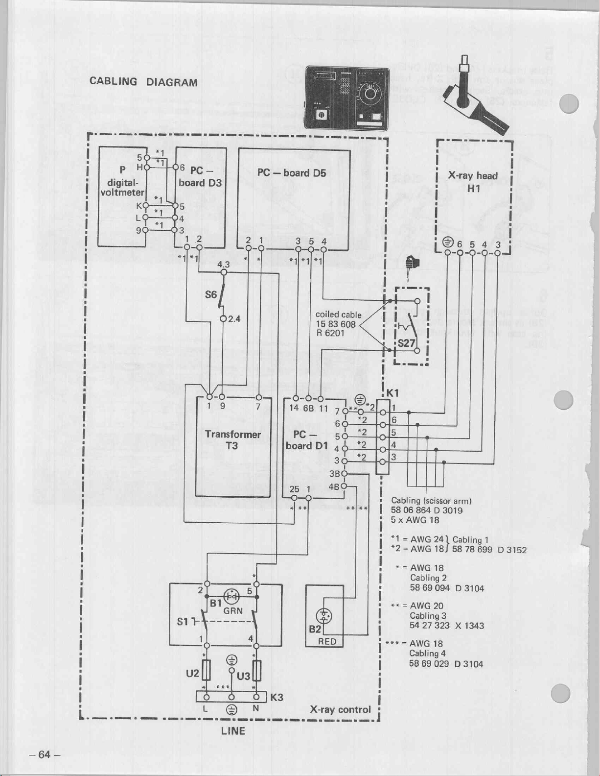
CABLING
DIAGRAM
г
I
I
i
digital-
!
lvoltmeter
|
i
|
|
|
i
|
|
i
I
i
P
ne
πι
As
PC
board
—
D3
PC
—
board
3
5
ή]
D5
4
o
coiled
15
R
cable
83
608
6201
ЕТ
I
|
2
I
|
:
I
|
|
|
,
5
RT
!
|
X-ray
65
head
H1
ἵ
403
7
7
5
I
|
!
eae
Lo-9-3-6-9-1
>
|
:
|
s
I
:
ㆍ
|
i
!
1
|
|
i
re
T3
-0-0
14
6B
PC
一
board
25
1
*|
**
B2
11
12
6o
50
D1
¿>
=]
48
—
RED
LB
一
人
=
2
**|**|
i
=
[Cle
To
|
|
*
|
i
i
İ
i
z
I
i
1
***
I
I
K1
4
3
Cabling
5806
5
x
AWG
*1
=
*2=
AWG
*
=
x*
=
=
AWG
Cabling
58
+
(scissor
864
D
3019
18
AWG
18)
AWG
18
Cabling
58
AWG
Cabling
54
69
27
69
2
094
20
3
323
18
4
029
arm)
Cabling
58
X
D
78
D
3104
1343
3104
1
699
D
3152
-
a
i
|
I
!
I
'
|
;
Transformer
i
|
i
|
|
:
|
|
I
i
u
|
I
—
64
—
|
i
i
L
©
LINE
N
X-ray
control
|
i
i
-
Page 65

DHHS — STATEMENTS
and
INFORMATION
according
to
21
CFR
Sub
Chapter
J
HELIODENT
=
1020.30
Instructions
of
the
1020.30
After a period
with
See:
Note:
It
is
with
Failure
this
70
(h)
(1)
for
OPERATING
(h)
(1)
of
the
DHHS
MAINTENANCE
the
responsibility
manufacturer’s
the
of
the
user
matter.
single-tank
(i)
the
use
of
the
INSTRUCTIONS:
(ii)
12
months
Performance
INSTRUCTIONS
of
the
recommended
to
do
so
relieves
dental
the
x-ray
HELIODENT
X-ray
Standard.
user
to
insure
the
generator
70
and
control
Maintenance
manufacturer
must
and/or
that
STORAGE
the
precautionary
be
serviced
to
INSPECTION
eguipment
Schedule.
or
his
is
agents,
statements
keep
it
in
PROCEDURE
maintained
from
all
are
part
compliance
in
compliance
responsibility
in
1020.30
Rated
leakage
(0,12
rated
7
Minimum
maximum
mA
continuous
mA
with a duty
1020.30
Cooling
Anode
1020.30
The
tube
Nominal
Nominal
Duty
cycle
(h)
(2)
technique
is
the
filtration
(h) (2)
curve
for
cooling
(h) (2)
is
designed
tube
current
peak
tube
(i)
peak tube
factors
equivalent
tube
cycle 1 :
in
potential
maximum
current
60)
useful
for
beam
(ii)
the
tube
housing
characteristic
(iii)
for
self-rectifying
(fixed)
potential
(fixed)
mode
of
operation
with
the
HELIODENT
70
kV
70
kV/0,12
2,7
mm
page
page
7
DCmA
70
kV
1:
60
Al
27
29
only.
in
DCmA
at
70
seconds
kV
—
65
—
Page 66
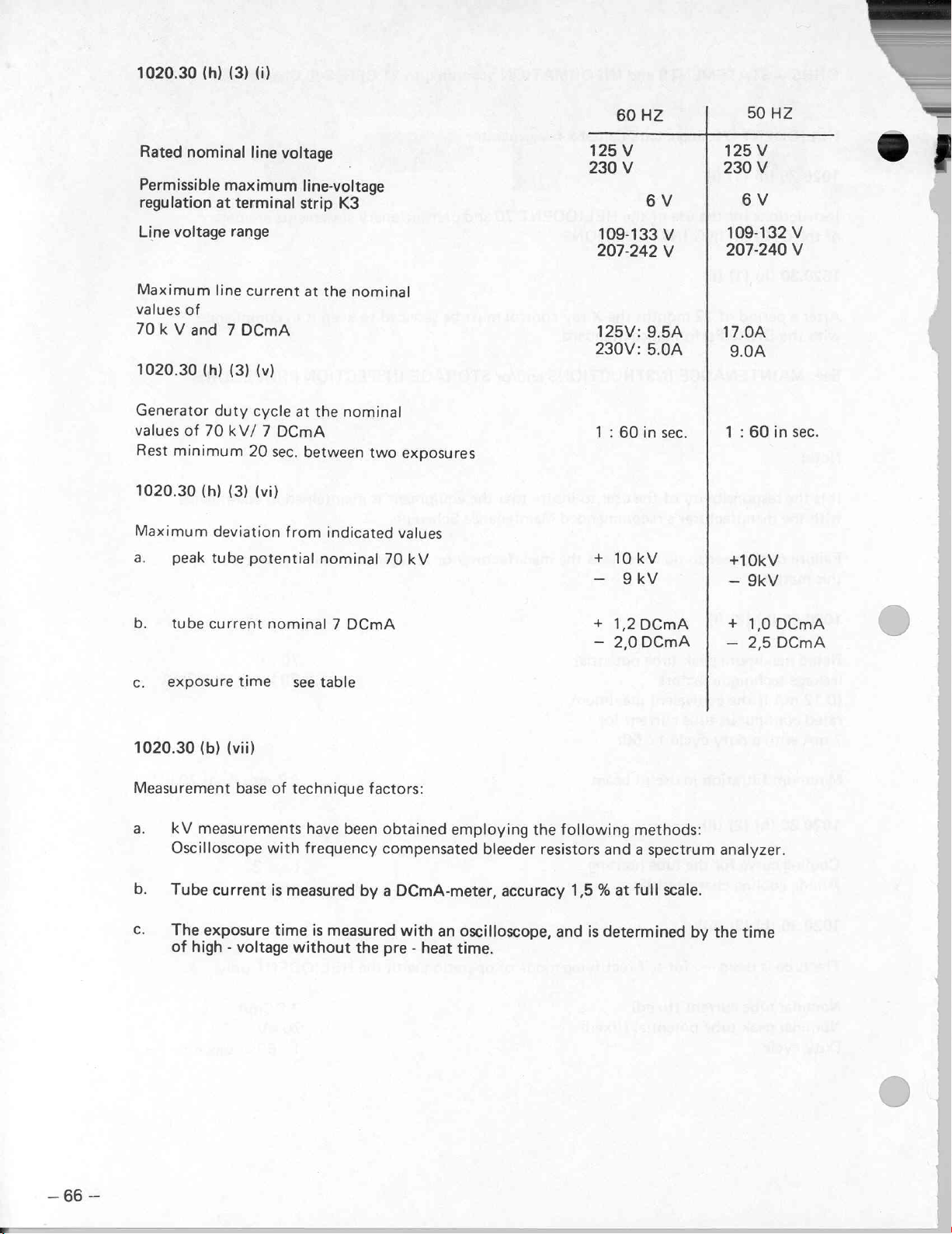
1020.30
Rated
Permissible
regulation
Line
(h)
nominal
at
voltage
(3)
(i)
line
maximum
terminal
range
voltage
line-voltage
strip
K3
60
125
V
230
V
109-133
207-242
HZ
6
V
V
V
50
125
V
230V
6V
109-132
207-240
HZ
=
o;
V
V
Maximum
values
70k
1020.30
Generator
values
Rest
1020.30
Maximum
a.
b.
c.
of
Vand
of
minimum
peak
tube
exposuretime
line
current
7DCmA
(h)
(3)
duty
70
kV/ 7 DCmA
20
(h)
(3)
deviation
tube
potential
current
at
the
(v)
cycle
at
the
sec.
between
(vi)
from
indicated
nominal
nominal 7 DCmA
see
table
nominal
nominal
two
70
exposures
values
kV
125V:
230V:
1:
60
+
10kV
Z:
+
1.2
2.0
9.5A
5.0A
in
sec.
DCmA
DCmA
17.0A
9.0A
1 : 60
—
+10kV
ー
9kV
+
1.0
2,5
in
sec.
DCmA
DCmA
1020.30
Measurement
a.
b.
c.
—
66
—
(b)
(vii)
base
kV
measurements
Oscilloscope
Tube
current
The
exposure
of
high - voltage
of
technique
with
is
measured
time
without
factors:
have
been
frequency
by a DCmA-meter,
is
measured
the pre - heat
obtained
compensated
with
employing
an
oscilloscope,
time.
bleeder
accuracy
the
following
resistors
1,5 % at
and
is
methods:
and a spectrum
full
scale.
determined
by
analyzer.
the
time
Page 67
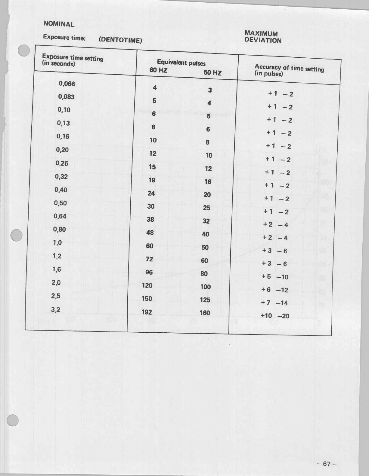
NOMINAL
Exposure
Exposure
(in
time:
time
seconds)
0,066
0,083
0,10
0,13
0,16
0,20
0,25
0,32
0,40
0.50
0,64
0,80
1,0
12
16
2,0
25
32
(DENTOTIME)
setting
60
4
5
6
8
10
12
15
19
24
30
38
48
60
72
96
120
150
192
Equivalent
HZ
pulses
50
16
20
25
32
40
50
60
80
100
125
160
3
4
5
6
8
10
12
HZ
MAXIMUM
DEVIATION
Accuracy
(in
pulses)
+1
+1
+1
+1
+1
+1
+1
ath
+1
+1
+2
+2
+3
一
+3
一
+5
+6
+7
+10
of
-2
一
-2
一
-2
一
一
—2
—4
一
4
6
6
一
10
一
12
一
14
一
20
time
一
2
2
2
2
sø
2
setting
—
67
—
Page 68

HELIODENT
70
70
kV, 7 DCmA
HU
«103
100
901
80
70
60
40
30
Cooling
curve
for
the
tube
housing
20
10
60
90
1
t
[min]
一
68
一
Page 69
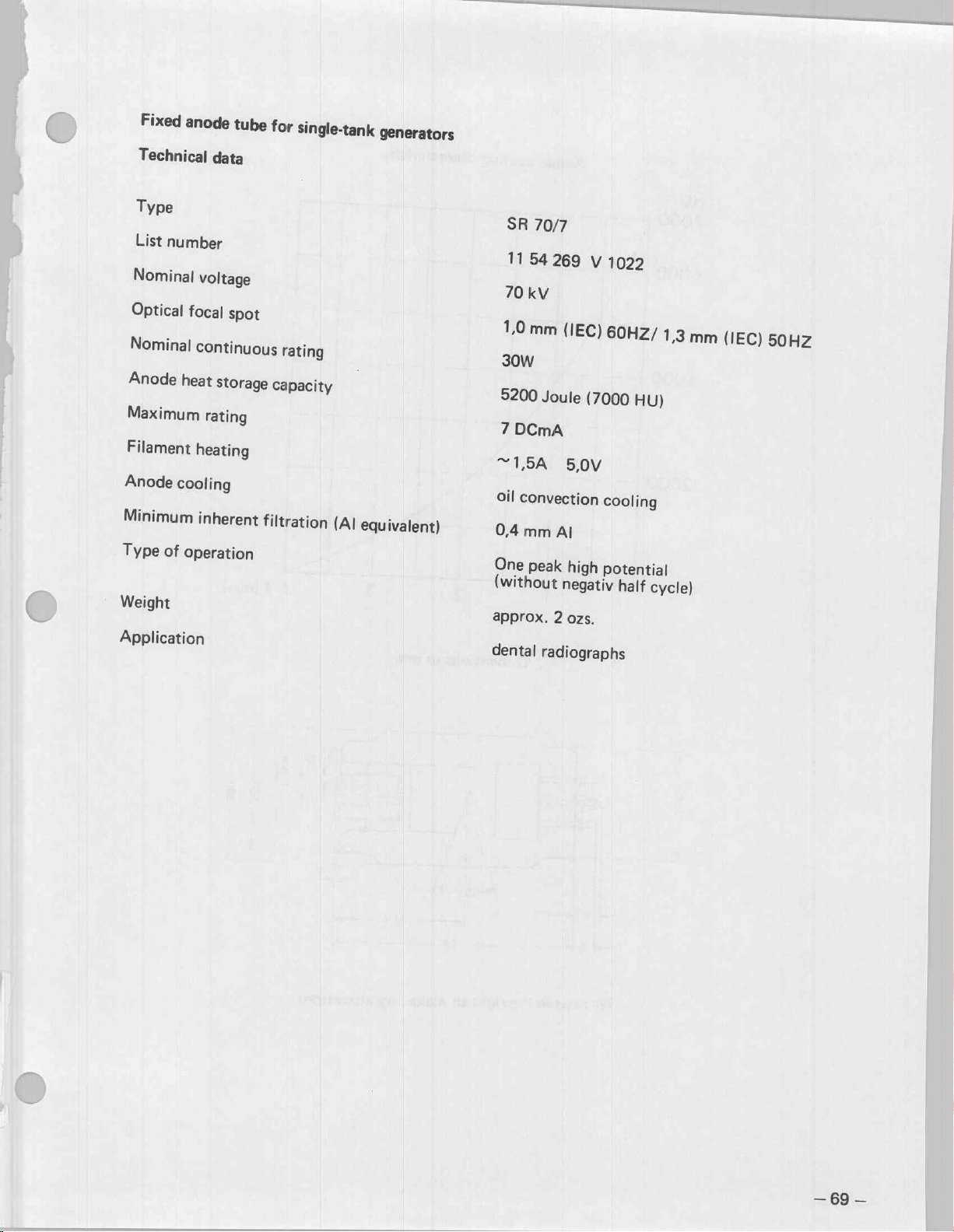
Fixed
anode
Technical
Type
List
number
Nominal
Optical
Nominal
Anode
Maximum
Filament
Anode
Minimum
Type
Weight
Application
voltage
focal
continuous
heat
heating
cooling
inherent
of
operation
tube
data
spot
storage
rating
for
single-tank
rating
capacity
filtration
(Al
generators
equivalent)
SR
70/7
11
54
70
kV
1,0
mm
30W
5200
Joule
7
DCmA
“ISA
oil
convection
0,4
mm
One
peak
(without
approx.
dental
radiographs
269
(IEC)
(7000
5,0V
AI
high
negativ
2
ozs.
V
1022
60Hz/
HU)
cooling
potential
half
1,3
mm
cycle)
(IEC)
50HZ
—
69
—
Page 70

enn
me
«ans
HU
7000
6000
4000
2000
Anode
cooling
characteristic
4
t(min)
me
Dimensions
in
mm
We
reserve
the
right
to
make
any
alterations
Page 71
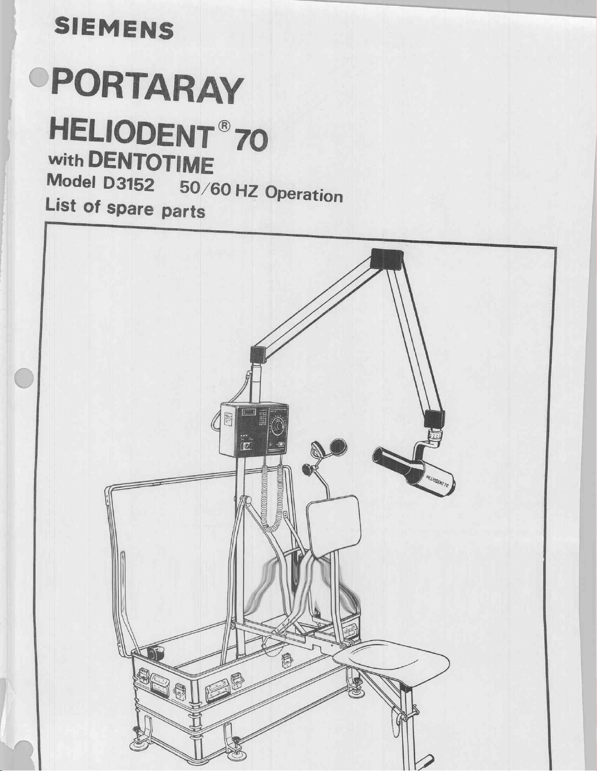
SIEMENS
SPORTARAY
„L
шез
Sáš
EŞ
ше
ン
@
に
35
List
of
spare
ミ
8
ES
parts
ω
nun
8
Z
Operation
Page 72

For
information
All
the
components
find
the
article
Unit
parts
number
shown,
shown
whose
(=
item
in
an
order
numbers
assembly
number)
are
drawing,
as
well
as
indicated
which
are
the
designation
in a circle,
available
as
spare
of
the
article
are a combination
parts,
have
in
the
of
two
an
item
opposite
or
several
number.
piece
single
Under
liste.
parts,
this
item
number,
you
a
will
NU
"ES
Copying
tity.
Offenders
model
or
of
this
document,
are
design,
and
liable
to
the
Scissor
giving
it
payment
arm
to
others
of
damages.
and
the
All
user
or
rights
are
communication
reserved
in
the
X-ray
DENTOTIME
of
the
event
control
contents
of
the
grant
thereof,
are
of a patent
forbidden
or
the
registration
without
express
autho-
of a utility
Carrying
with
devices,
structure
transformer
case
mounting
support
and
E
Seat
green
upright
assembly,
field
tubing,
HELIODENT
Seat
assembly,
green
field
70
tubing,
upright
Page 73

Pos.
1
58
1.1 | 2964
2
3
3.1 | 2964
4
5
6
7
7.1 | 2964633
7.2 | 2964641
7.3 |
7.4 | 2964666
7.5 | 2964674
7.6 | 2964682
7.7 | 29
7.8 | 2964
7.9 | 2964716
8
8.1 | 2964732
8.2 | 29
8.3 | 2964
8.4 | 29
9
9.1 | 29
9.2 | 2964
9.3 | 2964807
9.4 | 2964815
10.3 | 2964
10.4 | 58
10.5 | 58 89
11
11.1 | 2964
14.2 | 2964906
11.3 | 5889472
11.4 | 2978211
11.5 | 2978
11.6
|
196 | 3128
197 | 31
240
|
241 | 2978237
242
|
243 | 2978229
244 | 8612426
245 | 5859555
89
29
64
58
89
29
64
29
64
29
64617 D 3152
29
64625 D 3152
2964658
64
29
64
64
64
29
64
64 781 D 3152
89456 D 3152
29
64
29
78
28
2978
10
20
431 D 3152
559 D 3152
567 D 3152
449 D 3152
583 D 3152
591 D 3152
609 D 3152
D
3152
D
3152
D
3152
D
3152
D
3152
D
3152
690 D 3152
708 D 3152
D
3152
724 D 3152
D
3152
740 D 3152
757 D 3152
765 D 3152
773 D 3152
799 D 3152
D
3152
D
3152
856 D 3152
464 D 3152
880 D 3152
898 D 3152
D3152
D3152
D
3152
203 D 3152
195
D
3152
154 B 1303
162 B 1303
245
D
3152
D
3152
288
B
1302
D
3152
X
1807
D3152
Art.-Nr.
Case
Pressure
Leveling
Subframe
Upright
Support
Support
Stud
Bracket
Threaded
Screw
Rail
Bracket
Receptacle
Base
Support
Support
Locking
Bracket
Retainer
Retainer
Bracket
Retainer
Receptacle
Receptacle
Receptacle
Retainer
Receptacle
Pouch
Strap
Strap
Bracket
Receptacle
Screw
Receptacle
Desiccant
Gasket
Adhesive
Fuse
Bayonet
Transformer
Socket
Fuse
Cable
Transformer
Screw
relief
bracket
compl.
support
left
right
with
knurled
left
bushing
plate
compl.
bracket
bracket
device
left
for
for
right
for
bracket
bag
(for
holder
catch
125V
10A
230V
for
for
for
for
for
valve
compl.
bracket
knop
(X-Ray
(chairsupport)
chairsupport,
chair
(chairsupport)
chairsupport,
230/125V
250V
arm)
scissor
PROCOMAT
PROCOMAT
PROCOMAT
PROCOMAT
Branogel
gasket)
arm
left
for
right
for
medium
X-Ray
X-Ray
left
right_
(ten
complete
slow
head
head
bags)
blow
Designation
with
16
DIN
1/4
locking
55473/B
x
1
1/4”
device
4101-8-66-1
TA294-10-10-R
4101-1-55
4101-1-50
4101-2-50
4101-3-55
4101-3-54
4101-3-58
4101-8-71
4101-8-78
4101-8-76
4101-8-73
4101-8-72
4101-8-87
4101-8-105
4101-8-106
4101-8-117
51L1-1X-5AA
4101-8-90
4101-8-94
4101-8-113
4101-8-90
4101-8-91
4101-8-99
4101-8-96
4101-8-97
4101-8-95
4101-8-114
4101-8-126
4101-8-127-1
4101-8-128-1
4101-8-81
4101-8-83
4101-8-82
4101-8-74-3
4101-9-00
4101-8-141
-4
2
06.86
PORTARAY
D
3152.081.02.04.02
Page 74
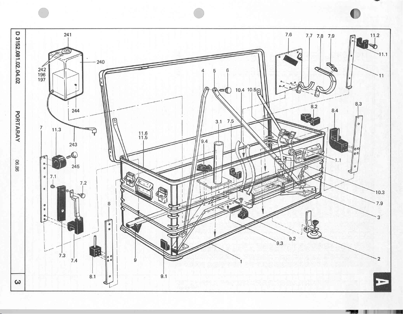
D
3152.081.02.04.02
PORTARAY
06.86
Page 75
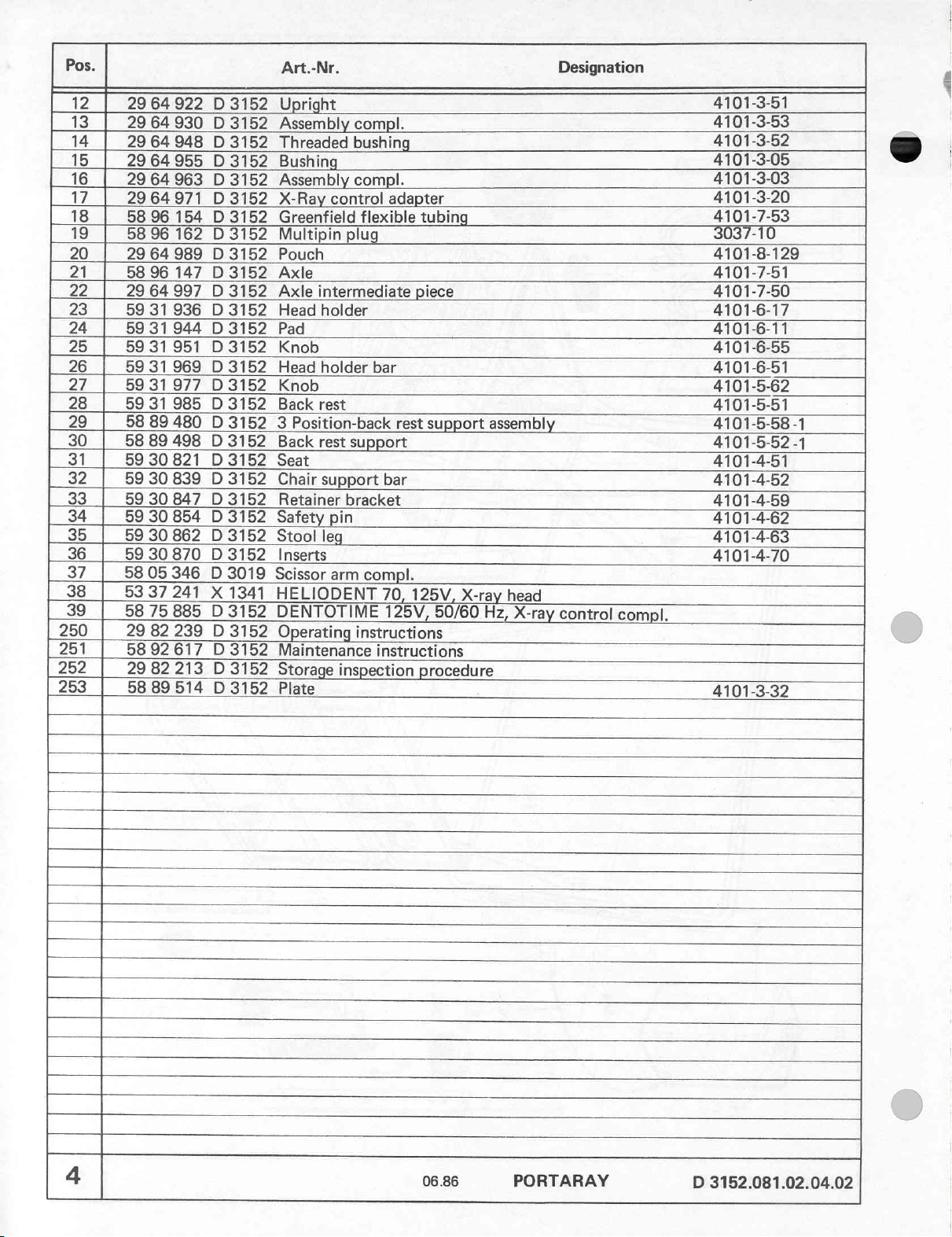
Pos.
12
13
14
15
16
17
18
19
20 29
21
22
23
24 59
25 59
26
27
28 59
29
30
31
32
33
34
35
36
37
38
39
250
251
252
253
4
2964922
29
64
29
64
29
64955 D 3152
29
64
2964971
58 96
58 96
64
58
96
29
64
59
31
31
31951 D 3152
59
31
59
31
31
58
89
58
89
59
30
59
30
59
30
59
30
59
30
59
30
58
05
53
37
58
75
29
82
58 92
29
82
58
89
D
3152
930 D 3152
948 D 3152
963 D 3152
D
3152
154 D 3152
162 D 3152
989 D 3152
147 D 3152
997 D 3152
936 D 3152
944 D 3152
969 D 3152
977 D 3152
985 D 3152
480 D 3152 3 Position-back
498 D 3152
821 D 3152
839 D 3152
847 D 3152
854 D 3152
862 D 3152
870 D 3152
346 D 3019
241
X
1341
885
D
3152
239 D 3152
617 D 3152
213 D 3152
514
D
3152
Art.-Nr.
Upright
Assembly
Threaded
Bushing
Assembly
X-Ray
Greenfield
Multipin
Pouch
Axle
Axle
intermediate
Head
holder
Pad
Knob
Head
holder
Knob
Back
rest
Back
rest
Seat
Chair
support
Retainer
Safety
Stool
leg
Inserts
Scissor
HELIODENT
DENTOTIME
Operating
Maintenance
Storage
Plate
compl.
bushing
compl.
control
pin
arm
inspection
adapter
flexible
plug
bar
rest
support
bar
bracket
compl.
70,
125V,
instructions
instructions
tubing
piece
support
125V,
X-ray
50/60
procedure
06.86
assembly
head
Hz,
X-ray
PORTARAY
Designation
control
compl.
4101-3-51
4101-3-53
4101-3-52
4101-3-05
4101-3-03
4101-3-20
4101-7-53
3037-10
4101-8-129
4101-7-51
4101-7-50
4101-6-17
4101-6-11
4101-6-55
4101-6-51
4101-5-62
4101-5-51
4101-5-58
4101-5-52
4101-4-51
4101-4-52
4101-4-59
4101-4-62
4101-4-63
4101-4-70
4101-3-32
D
3152.081.02.04.02
-1
-1
ati
Page 76

D
3152.081.02.04.02
PORTARAY
06.86
Page 77
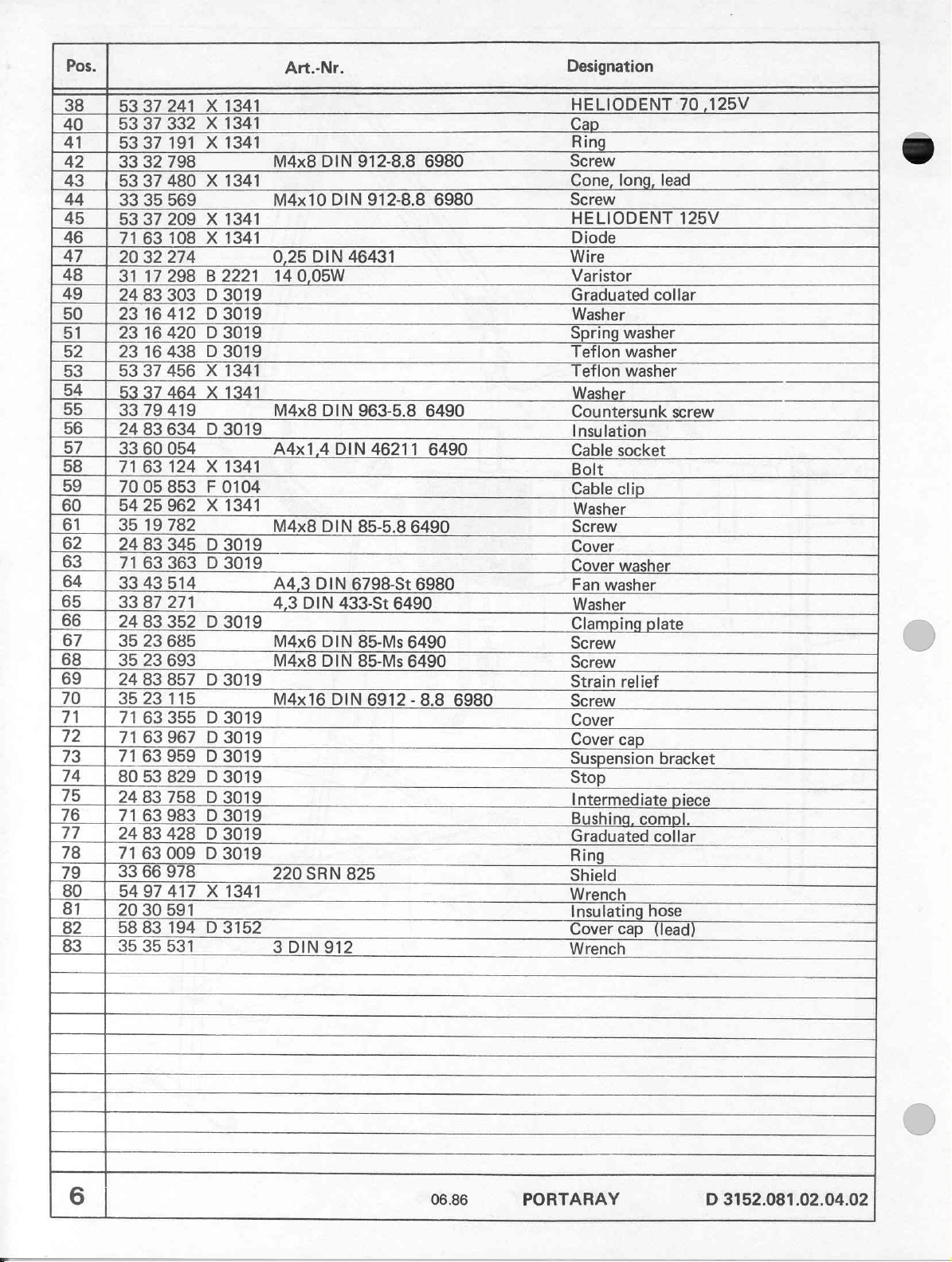
Pos.
38
40
41
42
43
44
45
46
47
48
49
50
51
52
53
54
55
56
57
58
59
60
61
62
63
64
65
66
67
68
69
70
71
72
73
74
75
76
77
78
79
80
81
82
83
241
37
53
332
37
53
191
37
53
798
32
33
480
37
53
569
35
33
209
37
53
108
63
71
274
32
20
298
17
31
303
83
24
412
16
23
420
16
23
438
16
23
456
37
53
464
37
53
419
79
33
2483634
054
60
33
7163124
853
05
70
54
25
962
782
19
35
345
83
24
71
63
363
514
43
33
271
87
33
352
83
24
685
23
35
693
23
35
83857
24
115
23
35
355
63
71
7163967
7163959
829
53
80
24
83
758
71
63983
24
83
428
009
63
71
978
66
33
54
97
417
591
30
20
194
83
58
531
35
35
X
X
X
X
X
X
2221
B
D
D
D
D
X
X
D
X
0104
F
X
D
D
D
D
D
D
D
D
D
D
D
D
X
D
1341
1341
1341
1341
1341
1341
3019
3019
3019
3019
1341
1341
3019
1341
1341
3019
3019
3019
3019
3019
3019
3019
3019
3019
3019
3019
3019
1341
3152
Art.-Nr.
14
DIN
DIN
DIN
DIN
0,05W
DIN
DIN
DIN
DIN
DIN
DIN
DIN
DIN
SRN
912
433-St
M4x8
M4x10
0,25
M4x8
A4x1,4
M4x8
A4,3
4,3
M4x6
M4x8
M4x16
220
3
912-8.8
912-8.8
46431
963-5.8
46211
85-5.8
6798-St
6490
85-Ms
85-Ms
6912
825
6980
6980
6490
6490
6490
6980
6490
6490
8.8
-
6980
Designation
HELIODENT
Cap
Ring
Screw
lead
Cone,
Screw
Wire
Varistor
Graduated
Spring
Teflon
Teflon
Countersunk
Cable
Cable
Cover
Cover
Clamping
Screw
Screw
Strain
Screw
Cover
Cover
Suspension
Stop
Bushing,
Graduated
Ring
Shield
Wrench
Insulating
Cover
Wrench
long,
HELIODENT
Diode
collar
Washer
washer
washer
washer
Washer
Insulation
socket
Bolt
clip
Washer
Screw
washer
washer
Fan
Washer
plate
relief
cap
bracket
Intermediate
compl.
collar
hose
(lead)
cap
,125V
70
125V
screw
piece
6
06.86
PORTARAY
3152.081.02.04.02
D
Page 78
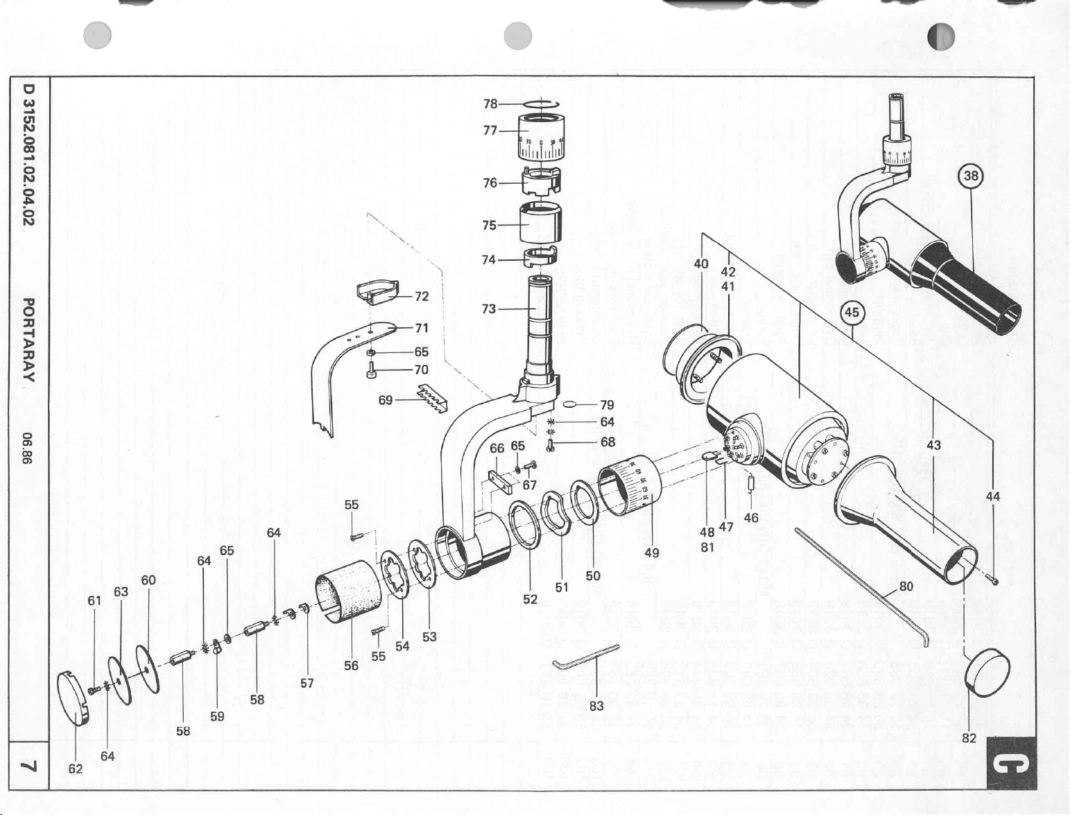
0
20'70'00'180'0916
AVHVLHOd
98'90
Page 79
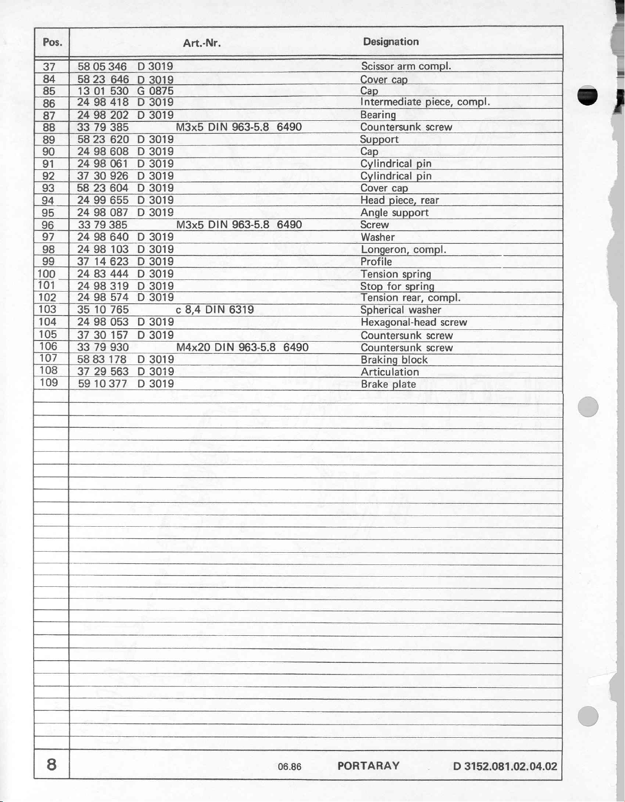
Pos.
37
84
85
86
87
88
89
90
91
92
93
94
95
96
97
98
99
|100
101
102
103
104
105
106
107
108
109
|
|
|
|
|
346
05
58
646
23
58
530
01
13
418
98
24
202
98
24
385
79
33
620
23
58
608
98
24
061
98
24
926
30
37
604
23
58
655
99
24
087
98
24
385
79
33
640
98
24
103
98
24
623
14
37
444
83
24
319
98
24
574
98
24
765
10
35
053
98
24
30157
37
930
79
33
5883178
29563
37
5810377
D
D
G
D
D
D
D
D
D
D
D
D
D
D
D
D
D
D
D
D
D
D
D
3019
3019
0875
3019
3019
3019
3019
3019
3019
3019
3019
3019
3019
3019
3019
3019
3019
3019
3019
3019
3019
3019
3019
Art.-Nr.
8,4
DIN
DIN
DIN
DIN
M3x5
M3x5
c
M4x20
963-5.8
963-5.8
6319
963-5.8
6490
6490
6490
Designation
compl.
Scissor
Cover
Cap
Intermediate
Bearing
Countersunk
Support
Cap
Cylindrical
Cylindrical
Cover
Head
Angle
Screw
Washer
Longeron,
Profile
Tension
Stop
Tension
Spherical
Hexagonal-head
Countersunk
Countersunk
Braking
Articulation
Brake
arm
cap
cap
piece,
support
compl.
spring
spring
for
rear,
washer
block
plate
piece,
screw
pin
pin
rear
compl.
screw
screw
ous
yp
compl.
ee
screw
8
06.86
PORTARAY
3152.081.02.04.02
D
Page 80

0
200'70'00'180'0916
AVHVLHOd
98'90
Gi
Page 81
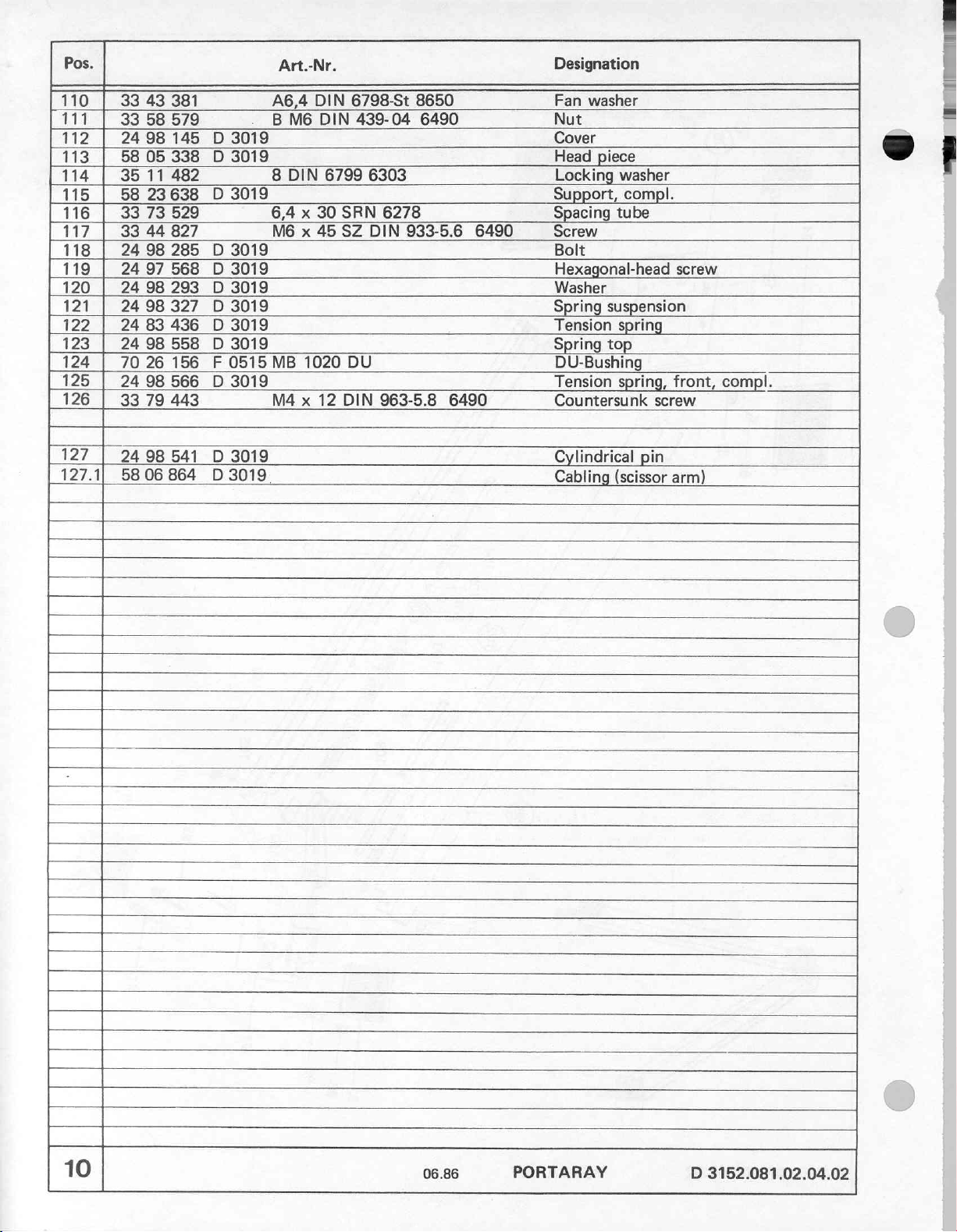
Pos.
110
111
112
113
114 | 35
115
116 | 33
117 | 33 44
118 | 24 98
119
120 | 24 98
121
122
123 | 24 98
124 | 70
125 | 24 98
126 | 33 79
127
127.1)
33
33
24 98
58
58
24
24
24 83
24
58
Art.-Nr.
43
381
58
579
145 D 3019
05
338 D 3019
11
482
23638
73
97
98
26
98
06864
D
529
827
285 D 3019
568 D 3019
293 D 3019 Washer
327 D 3019
436 D 3019
558 D 3019
156 F 0515
566 D 3019
443
541 D 3019
D
3019
3019
A6,4
DIN
B
M6
DIN
8
DIN
6799
6,4 x 30
M6 x 45
MB
1020
M4 x 12
6798-St
439-04
6303
SRN
6278
SZ
DIN
DU
DIN
963-5.8
8650
6490
933-5.6
6490
6490
Designation
Fan
washer
Nut
Cover
Head
piece
Locking
Support,
Spacing
Screw
Bolt
Hexagonal-head
Spring
Tension
Spring
DU-Bushing
Tension
Countersunk
Cylindrical
Cabling
washer
compl.
tube
suspension
spring
top
spring,
screw
pin
(scissor
screw
front,
arm)
OS
-ej
compl.
10
06.86
PORTARAY
D
3152.081.02.04.02
Page 82

D
3152.081.02.04.02
PORTARAY
06.86
11
Page 83
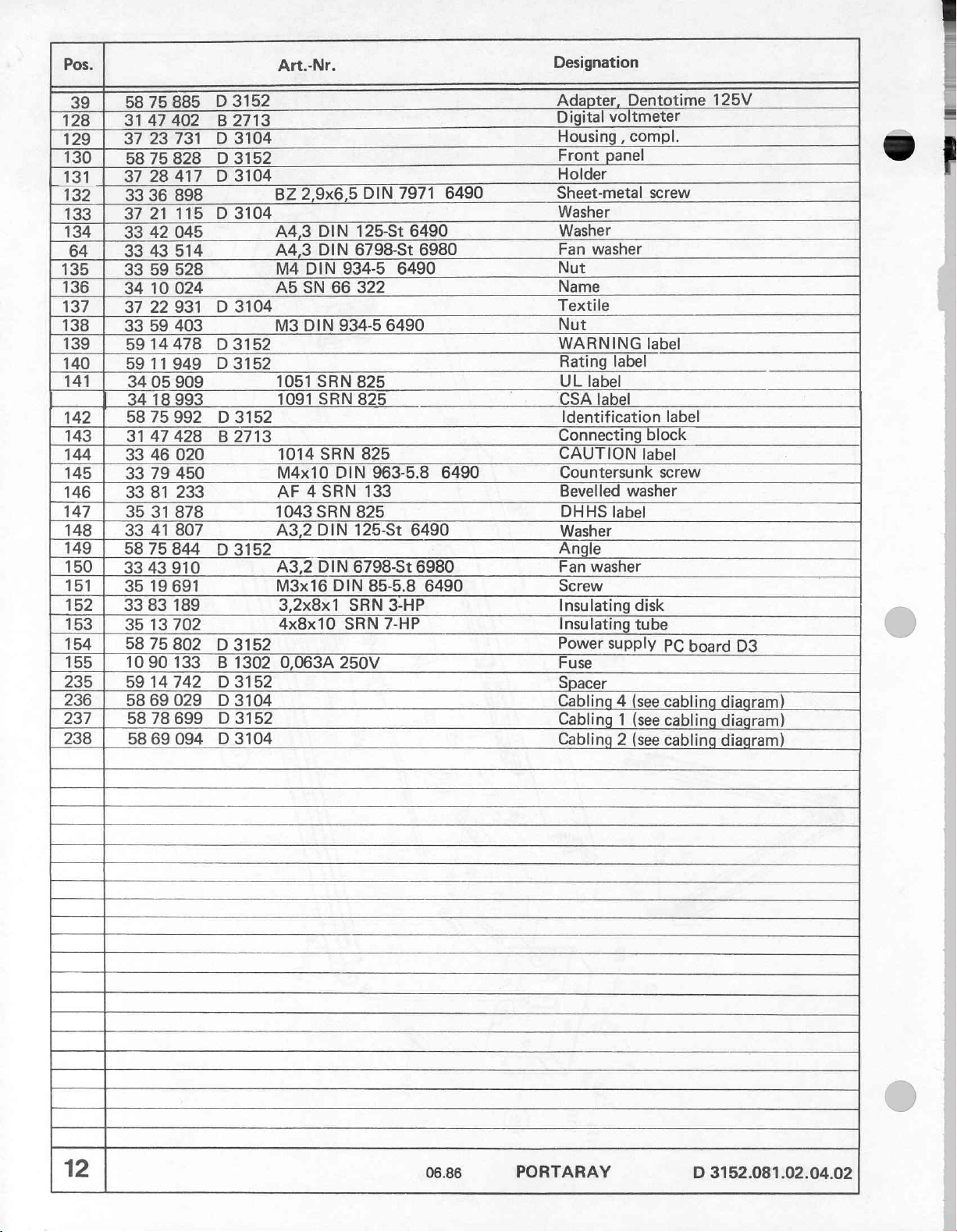
Pos.
75
39
128 | 3147402
129
130
131
132
133
134
64
135
136
137
138
139
140
141
142
143
144
145
146
147
148
149
150 | 3343
151
152 | 3383189
153
154
155
235
236
237
238
58
23731
37
75
58
28
37
33 36
37
21
33
42
33
43
33
59
34
10
37
22931
33
59
5914478
5911949
34
05
34
18
58
75992
3147
33
46
33
79
33
81
35
31
33
41
58
75
35
19
35
13
58 75
10
90
59
14742
5869029
5878699
58
69
3152
D
885
B2713
3104
D
3152
D
828
3104
D
417
898
115 D 3104
045
514
528
024
D
3104
403
D
3152
D
3152
909
993
D
3152
428 B 2713
020
450
233
878
807
844 D 3152
910
691
702
802 D 3152
133 B 1302
D
3152
D
3104
D
3152
094 D 3104
Art.-Nr.
BZ
2,9x6,5
A4,3
DIN
A4,3
DIN
M4
DIN
A5
SN
66
M3
DIN
1051
SRN
1091
SRN
1014
SRN
M4x10
AF 4 SRN
1043
SRN
A3,2
DIN
A3,2
DIN
M3x16
3,2x8x1
4x8x10
0,063A
DIN
125-St
6798-St
934-5
322
934-5
825
825
825
DIN
133
825
125-St
6798-St
DIN
SRN
SRN
250V
7971
6490
6980
6490
6490
963-5.8
6490
6980
85-5.8
3-HP
7-HP
6490
6490
6490
Designation
Adapter,
Digital
Housing
Front
Holder
Sheet-metal
Washer
Washer
Fan
Nut
Name
Textile
Nut
WARNING
Rating
UL
label
CSA
Identification
Connecting
CAUTION
Countersunk
Bevelled
DHHS
Washer
Angle
Fan
Screw
Insulating
Insulating
Power
Fuse
Spacer
Cabling 4 (see
Cabling 1 (see
Cabling 2 (see
Dentotime
voltmeter
compl.
,
panel
screw
washer
label
label
label
block
label
washer
label
washer
disk
tube
supply
screw
125V
label
PC
board
cabling
cabling
cabling
D3
diagram)
diagram)
diagram)
12
06.86
PORTARAY
D
3152.081.02.04.02
Page 84

D
3152.081.02.04.02
138
|
150
148
153
235
43
1
128
146
145
|
148,152,
о
D
=
>
고
>
<
Ἱ
06.86
k
155
=
©
142—
140
1474
141
144
„=
X
|
|
-」
の の の
Lad
P
da
a
io
ES
131
a
に
13
Page 85

Pos.
64
156
157
150 | 3343910
138 | 33
158 | 3540655
79 33 66
159
160
134
64
161
162
163
164
165
166
167
168
169
170
171
172
173
174
175
176
177
61
178 | 33
179
180
181
231
232 | 5914734
233
33 43
58
66
35 25
59
58 05
35 40
33
42
33 43
33
44
58
18992 D 3104
58
78616
70
17650 F 0112
58
75
2168
70
05
34
15
58
18950 D 3104
35
40
37
31
33
53
33
53
33 58
33
58
33
52
37
19788 D 3104
35
19
42
37
20091
33
59
58 32
59 14
35
19
514
686 D 3104
714
403
978
064 D 3104
309
045
514
850
D
3152
935 D 3104
243 Q 1212
887 F 0104
122
283
130 D 3104
356
364
843
926
796
782
094
D
3104
528
449 D 3104
718 D 3152
D
3152
840
Art.-Nr.
A4,3
DIN
M3x8
M4x8
220
A4,3
A4,3
SRN
M4x8
A4,3
M4
M4x16
A3,2
M3
DIN
SRN
M4x10
M4x8
M4x6
10
SRN
D10
SRN
SRN
SRN
E1
SRN
DIN
DIN
DIN
SZ
DIN
DIN
DIN
7175
DIN
7175
7175
DIN
DIN
6798-St
85-5.8
6798-St
934-5
DIN
825
DIN
85-5.8
125-St
6798-St
551
85-5.8
7174
7174
7174
85-5.8
125
934-5
DIN
85-5.8
6980
6490
6980
6490
933-Ms
6490
6490
6980
6490
6490
6490
Ms
6490
6490
6490
6490
Designation
Fan
washer
Fixing
Screw
Fan
Nut
Screw
Shield
Angle,
Screw
Washer
Fan
Threaded
Bracket
Holding
Grommet
Cable
Flange
Cable
L-Shield
Brake
Screw
Supporting
Clamp
Cover
Shield
N-Shield
Terminal
Wall
Screw
Washer
Fixing
Nut
Washer
Plate
Plate,compl.
Screw
angle
washer
compl.
washer
pin
plate
125V
socket
clip
rail
plate
clamp
adapter
angle
O
iy
a
14
06.86
PORTARAY
D
3152.081.02.04.02
Page 86

o
E
인
8
R
È
=
8
©
>
©
N
E
A
3
>
3
>
<
180,64
“|
169
|
[|
oj?
АН
==>
O
το
181
|
179
178
61
РЕ
CŘ
156
B!
170
“
170
—
171
ο
64
61
172
o
ο
2
À
οι
61,178,64,
167
—
|
|
157,150
,138
+
Page 87

Pos.
182 | 33
183
184
185 | 58
186 | 31
187 | 33 79
188 | 37
189 | 35
138 | 33
190
191
192 | 33
193 | 33
194 | 33
195 | 33
196 | 3128154
197 | 3128
198 | 1020288
199 | 58
|
58
15 16
33
37
32624
75927
83236 D 3152
18
31
21
59
86
31
43
42
80
59
75
D
095 R 8106
643 B 01051
856
627 D 3104
903
403
596
635 D 3104
530
144
912
593
B
162 B 1303
В
570 D 3152
Art.-Nr.
A1
3152
pol.
4,2x8x15
AM
M3
3,7x9x1,2
A5,1
A5,3
M5x12
M5
1303 5 x
6,3 x 32
1302
10A
SRN
3x32
DIN
DIN 6798-St
DIN
DIN
20
u. 6 x
250V
16
7859
SRN
DIN
934-5.
SRN
125-St
DIN
963-4.8
934-5
MM
medium
7-HP
85-5.8
6490
134-St
6490
6490
32
MM
FEK
6490
6490
6980
6490
FEU
031.1653
031.1662
slow
blow
06.86
Designation
Cable
Housing,
Transformer
PC
board
Control
Insulating
Insulating
Screw
Nut
Washer
Insulating
Fan
washer
Washer
Countersunk
Nut
Fuse
Bayonet
1/4 x 1
1/4”
Insulating
PORTARAY
binder
compl.
D5
switch
tube
bushing
ring
holder
catch
Fuse
plate
screw
D
3152.081.02.04.02
Page 88

Oi
EN
D
3152.081.02.04.02
PORTARAY
06.86
17
Page 89
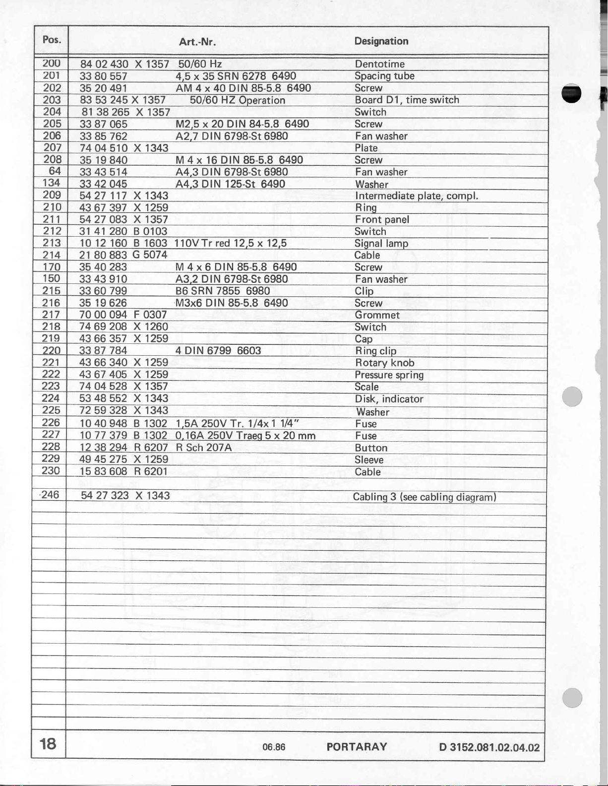
Pos.
200 | 8402430
201 | 3380557
202 | 35 20
203 | 83
204
| 8138265
205 | 33
206 | 33 85
207 | 7404510
208 | 35
64 | 3343514
134 | 3342
209 | 5427117
210 | 4367
211
212 | 3141280
213 | 1012
|
214
170 | 35
150 | 3343910
215 | 3360
216 | 35
217 | 7000094 F 0307
218
219 | 4366
220 | 3387
221
222 |
223 | 7404528
224 | 5348552
225 | 7259328
226 | 1040948
227 | 1077379
228 | 1238294
229 | 4945275
230 | 1583608
-246
18
53
87
19
54 27
21
80
40
19
74
69
43
66
4367405
5427323
X
491
245 X 1357
X
065
762
X
1343
840
045
X
1343
397 X 1259
083 X 1357
B
0103
160 B 1603
883 G 5074
283
799
626
208 X 1260
357 X 1259
784
340 X 1259
X
1259
X
1357
X
1343
X
1343
B
1302
B
1302
R
6207 R Sch
X
1259
R
6201
X
1357
1357
1343
Art.-Nr.
50/60
4,5 x 35
AM 4 x
50/60 HZ
M2,5 x 20
A2,7
DIN
M
4 x
16
A4,3
DIN
A4,3
DIN
110V
Tr
M 4 x 6 DIN
A3,2
DIN
B6
SRN
'M3x6
4
0,16A
DIN
1,5A
DIN
6799
250V
250V
207A
Hz
SRN
40
DIN
DIN
6798-St
DIN
6798-St
125-St
red
12,5 x 12,5
6798-St
7855
85-5.8
Tr.
Traeg
6278 6490
85-5.8
Operation
84-5.8
6980
85-5.8
85-5.8
6980
6603
1/4x
6490
6980
6490
6490
6980
6490
1 1/4"
5 x
06.86
6490
6490
20
mm
Designation
Dentotime
Spacing
Screw
Board
Switch
Screw
Fan
Plate
Screw
Fan
Washer
Intermediate
Ring
Front
Switch
Signal
Cable
Screw
Fan
Clip
Screw
Grommet
Switch
Cap
Ring
Rotary
Pressure
Scale
Disk,
Washer
Fuse
Fuse
Button
Sleeve
Cable
Cabling
PORTARAY
tube
D1,
time
washer
washer
panel
lamp
washer
clip
knob
spring
indicator
3
(see
switch
plate,
compl.
cabling
D
3152.081.02.04.02
diagram)
Page 90
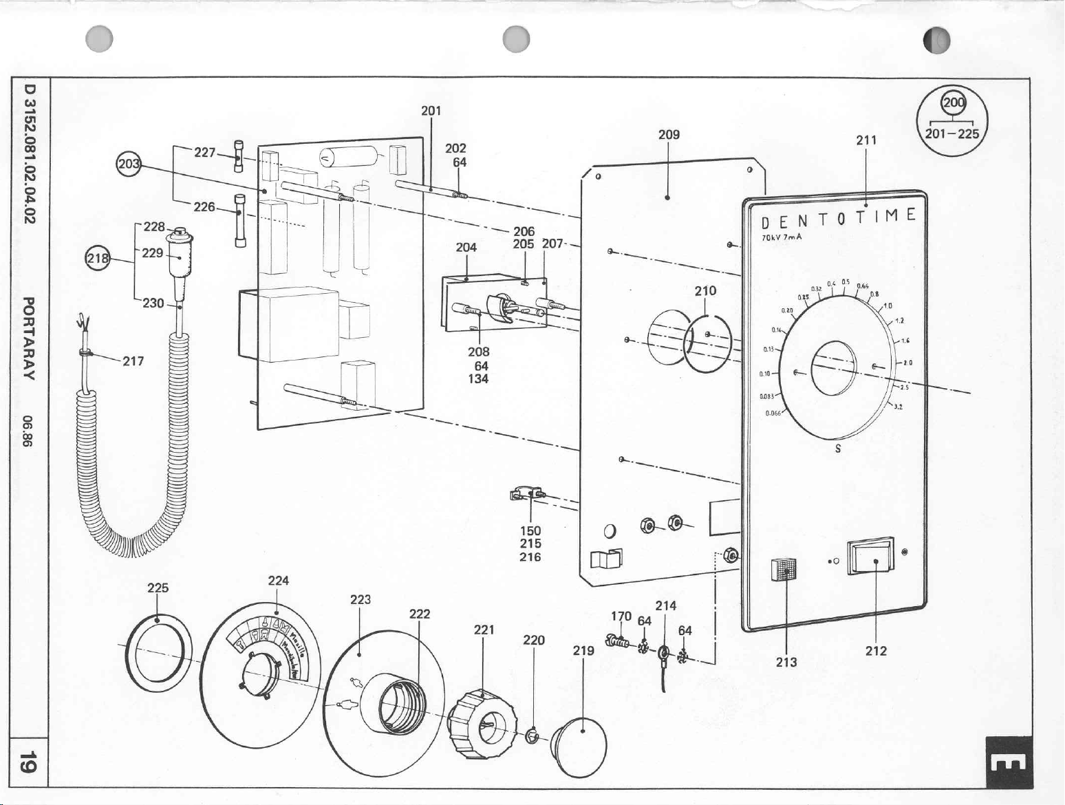
©
0
201
209
211
201—225
00'70'00'180'0916
AVUHVLHOd
98:90
—
204
-
u,
206
205
—
207-4
mz
-一
|
À
İDENTOTIME
70kV
7mA
6L
219
212
Page 91
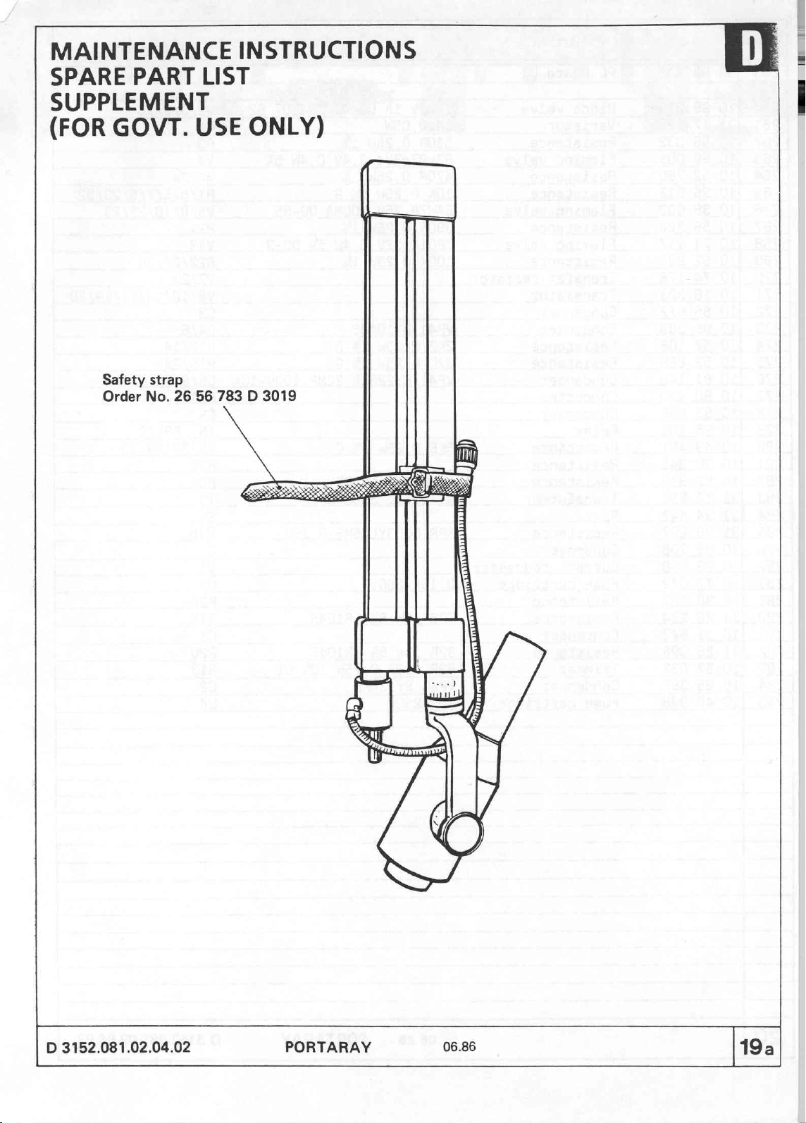
MAINTENANCE
WR
INSTRUCTIONS
SPARE
SUPPLEMENT
(FOR
PART
GOVT.
Safety
Order
strap
No. 26
LIST
USE
56
783 D 3019
ONLY)
VA
D
3152.081.02.04.02
PORTARAY
06.86
19a
Page 92

PC
Art.-Nr.
Board
Designation
D1
Diode
Varistor
Resistance
Fleming
Resistance
Resi
Flemin
Resistance
Ti
valve
i
ist
ndenser
valve
nce
n
1000V
14
510R
BZx97c2V4
470R
100K
1A
0,05W
0,25W
0,25W
7
25W
D0-41
2.4V
1N4007
0,4W
B2
V2/3/9/16
R2
R
V6/12/14/17/19/20
denser
i
Trimmer
Condenser
Fuse
cartridge
e
2R
10W
89P
100R
VP44
1,5A250V
BY334MB
06.86
5%
GR1045
0,75W
PORTARAY
10%
LI
D
3152.081.02.04.02.
Page 93
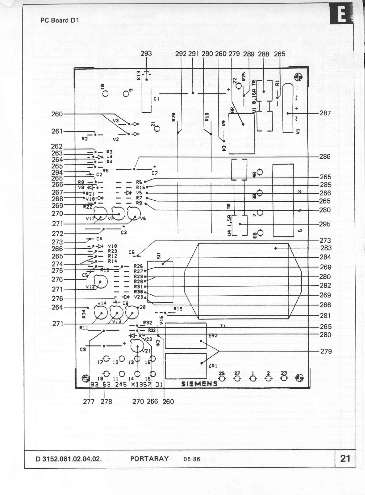
PC
Board
D1
=
=
一
261
262
263 二 十
DGA
265
20492
200
266
267—
268
269—+—
270 一 |
271—
572_ ニ ーー
273
26-95
265-
274——
275
276—
271
276————i
264—|
271
一
一
一
m
“一 * 一
1.
Vê
RUT
下
トー
ナー
イ
À
|
EE
cs
s
ο ο
=
_
E ?
R3
a
=-
+»
v16-
一
EH
vi
テラ
デー
ジー
Ad
8
0288
计
ゲ
<*
-
M
ca
==
-
—
28
v
823
2
12,
==
ー
Vid
EF.
N
ca
—
©
4+
—
_
0
m
=
3
>
Ribe—
%
R7
ce
de
Reed
Kep?
Ra
8
V23
zs
x
293
292
291
290
|
a
g に
я $
©
+
с?
6
Y
«|
20
a
a
a
23
Y
619
>
7
DE
“q
260
N
3
τπτ
o
|
=
279
|
boo
=
LA
同
s
=
5
289
LD
]
E
20
8
288
=
20
265
dE
」
&
Sai
|
3
+
5
A
OLE
be
\
7
/
È
7287
286
205
285
266
205
280
295
273
283
284
269
280
282
269
266
281
265
280
pa ig
al
li
D
3152.081.02.04.02.
da
245 x n
de
sa
PORTARAY
As
2.
E
Th
SIEMENS“
06.86
©
è
B
@
|
21
Page 94

PC
Art.-Nr.
Board
Designation
D3
Diode valve
urrent
Condenser
Condenser
Resistance
Resistance
Resistance
Condenser
Resi
Current
Fuse
Tension
Resistance
nsf
redresser
n
redresser
regulator
1000V
VP44
89p
213
B250
0,0
7805
TFB
1A
DO-41
BY334MB
R50K
CRV=1%
SMA
O
c1000/700
2
CU
4
1N4007
B1240
B2
PORTARAY
D
3152.081.02.04.02.
Page 95

PC
Board
D3
м
αι
Digital
31
300
301
302
voltmeter
47
402 B 2713
P
58
6
25
5.
802
5
03152
4
3
O
6
03
て
2
294
303
304
303
304
303
304
303
260
305
306
307
291
308
287
309
D
3152.081.02.04.02.
PORTARAY
06.86
23
Page 96

|
Art.-Nr.
Board
leming
urrent
Condenser
leming
Resistance
Transfer
Repeater
Condenser
Resistance
Fleming
Light
Resistance
Light
ndenser
Li
valve
redresser
valve
valve
emittin
emitting
emittin
D5
resistor
diode
1006
i
BAW76
VP44
ZPD
SBC
CA
G
r
SMA
green
75V
BY334MB
5,6
0309
145BE
0204
low
300MA
820K
TK100
Designation
DO-35
5%
ㅣ
+
SN
Resistance
06.86
PORTARAY
D
3152.081.02.04.02.
Page 97

PC
Board
D5
320
|
338
337
294
DANA
m
320
316
317
318
319
320
320
266
321
322
323
324
325
|
an
IN"
À
få
—
>
—
8D
ne
W
SsLLTTT1
+
==
(3+
e—
=
=
336
335
334
287
333
332
320
326
327
328
D
3152.081.02.04.02.
PORTARAY
329
06.86
318
25
 Loading...