

Page 1
Installation Instructions
Model D2300CPS
Multi Mode (850nm) Fiber Optic Interface
INTRODUCTION
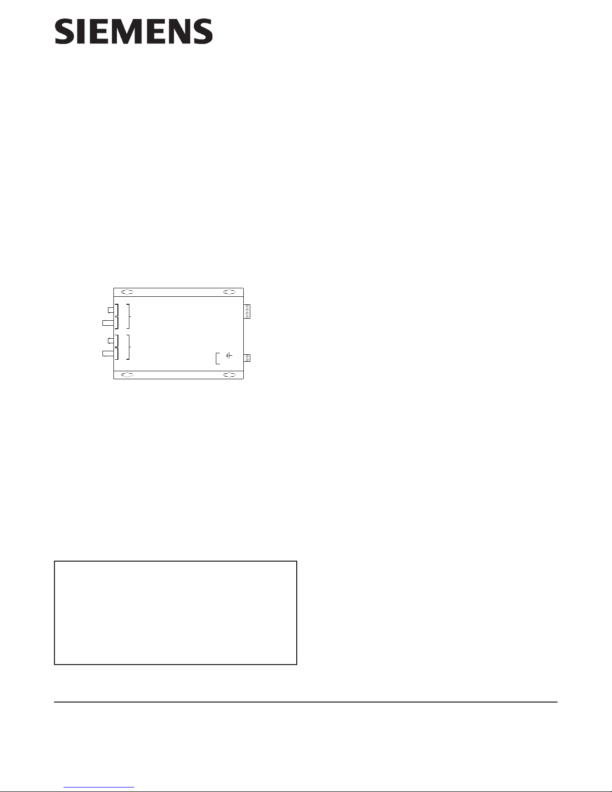
The Model D2300CPS from Siemens Industry, Inc. (See
Figure 1) is a Fiber Optic interface for the MXL’s RS-485
network (MNET or XNET), FireFinder XLS/Desigo Fire
Safety Modular/Cerberus PRO Modular network
(HNET or XNET) or HUB-4 FSI. It uses a two-fiber
(duplex) pair between each device. The D2300CPS can
function as either a repeater or an end point unit.
D2300CPS
A
B
RS485
POWER
DATA
REC
DATA
XTMR
DATA
REC
DATA
XTMR
WARNING: This module is NOT backwards
compatible with the original 5V D2300CP. This
unit uses +24VDC. Make sure to read the front of
the module and connect to the correct voltage.
Otherwise, serious damage to the unit will result.
Figure 1
D2300CPS Module
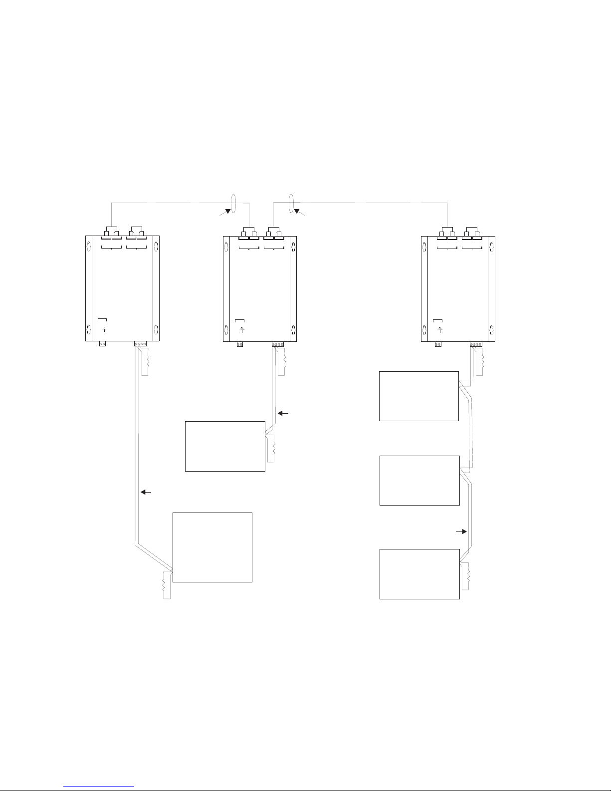
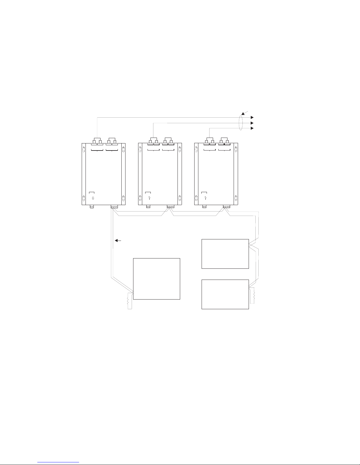
The D2300CPS can operate in either a daisy chain
(See Figure 2) or star configuration (See Figure 3).
This allows for network configurations that are not
possible with the RS-485 network alone.
WARNING:
The D2300CPS module is not listed for use by
Factory Mutual. Applications requiring fiber connectivity of voice modules/systems are therefore
not Factory Mutual listed.
WARNING:
Do not use the D2300CPS with CXL Systems.
POWER
(DO NOT USE) -4
(DO NOT USE) -3
-DATA-2
+DATA-1
+24 VDC
-2
-1
MOUNTING
The D2300CPS has four keyhole slots for #6 screws.
Mount the device in the locations listed below using
the four #6 screws provided.
A bracket (P/N 500-692880) is available for mounting
the D2300CPS in any MXL enclosure that will accept
a MOM-4 (See Figure 4). This bracket has the same
footprint as the MOM-4 and accommodates two
D2300CPS modules. An assembly kit is included with
the bracket that contains four nuts and eight screws.
Mount the bracket in the enclosure with the four nuts
at the positions labeled X (See Figure 4). Start four of
the 6-32 screws and slip the keyhole slots in the
D2300CPS
over them. Tighten the four screws.
System 3 style rails that mount on an MBR-2 or MME-3
backbox (P/N MSR-1) are also available and can be
used for mounting the D2300CPS with the System 3
MPFO Bracket. Up to three brackets can be installed on
a single rail.
A bracket, Model D2300-MP, is available for mounting
two D2300CPS modules in any FireFinder XLS/
Desigo Fire Safety Modular/Cerberus PRO Modular
CAB enclosure. The D2300-MP fits in the same
footprint as a CC-5 and mounts to the CAB-MP. A
hardware kit is provided for attaching the D2300-MP to
the CAB-MP and mounting two D2300CPS modules
onto the D2300-MP. Mount the D2300CPS modules
prior to installing the D2300-MP onto the CAB-MP.
Note that when using two D2300CPS modules, the
center two mounting holes on each D2300CPS share
the two center studs on the D2300-MP (See Figure 5).
ELECTRICAL CONNECTIONS
POWER INPUT
The D2300CPS uses filtered or unfiltered 24 VDC.
The D2300CPS can only be powered from the
sources listed in Table 1 on page 6.
Siemens Industry, Inc.
Building Technologies Division
Florham Park, NJ
P/N 315-050018-6
Siemens Canada, Ltd.
1577 North Service Road East
Oakville, Ontario
L6H 0H6 Canada
Page 2
MULTI MODE DUPLEX OPTICAL FIBER
POWER BUDGET - MAX LOSS
-8 dB 62.5/125 FIBER
-6 dB 50/125 FIBER
MULTI MODE DUPLEX OPTICAL FIBER
POWER BUDGET - MAX LOSS
-8 dB 62.5/125 FIBER
-6 dB 50/125 FIBER
CONNECTION
POWER
DATA
XTM
DATA
REC
B
D2300CPS
POWER
+24 VDC
-2
-1
NO
DATA
REC
DATA
XTMR
A
(DO NOT USE) -4
(DO NOT USE) -3
+DATA -1
-DATA-2
EOLR
120 OHMS, 1/4W
P/N 140-820150
RS-485
32 NODES MAX
SUPERVISED
SUPERVISED
PSR-1
POWER
DATA
XTMR
DATA
REC
B
D2300CPS
POWER
+24 VDC
-2
-1
DATA
XTMR
DATA
REC
A
(DO NOT USE) -4
(DO NOT USE) -3
+DATA-1
-DATA-2
EOLR
120 OHMS, 1/4W
P/N 140-820150
RS-485
32 NODES MAX
SUPERVISED
EOLR
120 OHMS, 1/4W
P/N 140-820150
SUPERVISED
RCC-1
RCC-1
CONNECTION
POWER
DATA
XTMR
DATA
REC
B
D2300CPS
POWER
+24 VDC
-2
-1
NO
DATA
XTMR
DATA
REC
A
(DO NOT USE) -4
(DO NOT USE) -3
+DATA-1
-DATA-2
EOLR
120 OHMS, 1/4W
P/N 140-820150
MMB
USE THE 120 ¼ W, 5%
EOL RESISTOR ASSEMBLY,
AS APPLICABLE:
P/N 140-820150 (MMB-1/-2)
OR P/N 140-049099 (MMB-3)
W,
Daisy Chain Configuration (MNET Shown)
Figure 2
2
32 NODES MAX
RS-485
SUPERVISED
PSR-1
EOLR
120 OHMS, 1/4W
P/N 140-820150
Page 3
CONNECTION
POWER
DATAPXTMR
DATAPREC
B
MULTI MODE DUPLEX OPTICAL FIBER
POWER BUDGET - MAX LOSS
-8 dB 62.5/125 FIBER
-6 dB 50/125 FIBER
NO
DATAPXTMR
DATAPREC
A
CONNECTION
DATA
XTMR
DATA
REC
B
NO
POWER
DATA
XTMR
DATA
REC
A
CONNECTION
POWER
DATA
XTMR
DATA
REC
B
SUPERVISED
TO ADDITIONAL
D2300CPS
NO
DATA
XTM
DATA
REC
A
MODULES
D2300CPS
POWER
+24 VDC
-2
-1
USE THE 120 ¼ W, 5%
EOL RESISTOR ASSEMBLY,
AS APPLICABLE:
P/N 140-820150 (MMB-1/-2)
OR P/N 140-049099 (MMB-3)
(DO NOT USE) -4
(DO NOT USE) -3
+DATA-1
-DATA-2
W,
D2300CPS
POWER
+24 VDC
-2
-1
RS-485
32 NODES MAX
SUPERVISED
MMB
D2300CPS
(DO NOT USE) -4
(DO NOT USE) -3
+DATA-1
-DATA-2
POWER
+24 VDC
-1
(DO NOT USE) -4
(DO NOT USE) -3
+DATA-1
-DATA-2
-2
PSR-1
EOLR
PSR-1
120 OHMS, 1/4W
P/N 140-820150
Figure 3
Star Configuration (MNET Shown)
3
Page 4

X
X
-1
-2
-DATA-2
+DATA-1
+24VDC
(DONOT USE) -4
(DONOT USE) -3
POWER
BRACKET
P/N 500-692880
D2300CPS
A
B
DATAPREC
DATAPREC
DATAPXTMR
POWER
-DATA-2
+DATA-1
(DONOT USE) -4
(DONOT USE) -3
DATAPXTMR
-1
-2
+24VDC
POWER
OMM-1
D2300CPS
A
B
DATAPREC
DATAPREC
DATAPXTMR
DATAPXTMR
POWER
WARNING
DISCONNECT POWER
PRIOR TO
REMOVING
TERMINAL
BLOCK PROTECTION
Figure 4
Mounting the D2300CPS in an MBR-2 or MME-3 Backbox
FIBER OPTIC CABLE
D2300-MP
POWER
DATA
XTMR
DATA
XTMR
DATA
REC
DATA
REC
B
A
POWER
DATA
XTMR
DATA
XTMR
DATA
REC
DATA
REC
B
A
D2300CPS D2300CPS
POWER
+24 VDC
-1
+DATA-1
-DATA-2
-2
POWER
(DO NOT USE) -4
(DO NOT USE) -3
+24 VDC
-2
-1
(DO NOT USE) -4
(DO NOT USE) -3
+DATA-1
-DATA-2
POWER LIMITED HNET/XNET
ROUTE AS SHOWN
Z
O
N
E
1
Z
O
N
E
2
DLC
RESET
POWER
CARDFAIL
HNETFAIL
GNDFAULT
ALARM
TROUBLE
ZONESSTATUS
CLASSA OPEN
CLASSA RETURN
SHORT
CLASSA OPEN
CLASSA RETURN
SHORT
HUNDREDS
TENS
ONES
HNET
NIC-C
RESET
POWER
CARDFAIL
CANFAIL
HNETFAIL
XNETFAIL
GNDFAULT
LOOPA FAIL
LOOPB FAIL
ACTIVENETWORKS
CAN
HNET
XNET
HNET/XNETSTYLE
STYLE7
STYLE4
GROUNDFAULT
ENABLED
DISABLED
NETWORK
PORT
HUNDREDS
TENS
ONES
HNET
P5
1
P4
34
12
PSC-12
RESET
POWER
MODULE FAIL
CAN FAIL
HNETFAIL
GND FAULT
24V 12AFAIL
24V 4AFAIL
HUNDREDS
TENS
ONES
HNET
P9
_
+
TB4
2
1
_
+
_
TB1
1
7
BATTERY
—
O
OFF
TB2
19
13
+
6
2
1
TB3
12
ON
P12
GND
24
N
H
18
CAB-1
Mounting the D2300CPS in a CAB-1 Backbox
Figure 5
4
Page 5

POWER BUDGET - MAX LOSS
SUPERVISED
-8 dB 62.5/125 FIBER
- 6 dB 50/125 FIBER
N.C.
N.C.
DATA
REC
DATA
XTMR
DATA
REC
DATA
XTMR
DATA
REC
DATA
XTMR
DATA
REC
DATA
XTMR
A
B
A
B
D2300CPS
D2300CPS
END POINT
FACP
RS-485 NETWORK
MNET/HNET/XNET
(SEE FIGURES 7, 8 & 9)
REPEATER
FACP
POWER BUDGET - MAX LOSS
SUPERVISED
-8 dB 62.5/125 FIBER
- 6 dB 50/125 FIBER
N.C.
N.C.
DATA
REC
DATA
XTMR
DATA
REC
DATA
XTMR
A
B
D2300CPS
END POINT
FACP
Figure 6
Wiring the D2300CPS as both a Repeater and End Point Unit
RS-485 RATINGS:
8V P-P
150mA MAX
80 OHMS MAX
18 AWG MIN
(DO NOT USE)
(DO NOT USE)
D2300CPS
(DO NOT USE)
(DO NOT USE)
D2300CPS
(DO NOT USE)
(DO NOT USE)
D2300CPS
-DATA
+DATA
-DATA
+DATA
-DATA
+DATA
120 OHMS, 1/4W
-4
-3
-2
-1
-4
-3
-2
-1
-4
-3
-2
-1
EOLR
P/N 140-820150
USE THE 120 ¼ W, 5%
EOL RESISTOR ASSEMBLY,
AS APPLICABLE:
P/N 140-820150 (MMB-1/-2)
OR P/N 140-049099 (MMB-3)
STYLE 4 MNET
SUPERVISED
SUPERVISED
1234
W,
EOLR
120 OHMS, 1/4W
P/N 140-820150
SUPERVISED
120 OHMS, 1/4W
P/N 140-820150
EOLR
TB1
(DO NOT USE)
4
(DO NOT USE)
3
2
1
REFER TO NET-7
INSTALLATIONINSTRUCTIONS
P/N 315-091914
MMB
RS-485 RATINGS:
8V P-P
150mA MAX
80 OHMS MAX
18 AWG MIN
TB1
STYLE 7 MNET
Wiring the RS-485 MNET Network in Style 4 and Style 7
NET-7
MOM-4
Figure 7
5
Page 6

METSYSECRUOSREWOP
LXM21-95BT;5-41BT:2-BMM
redniFeriF
ogiseD/SLX
riF
ytefaSe
-ebreC/raludoM
ORPsur
raludoM
1elbaT
For non-power limited wiring, the PLM-35 (Installation
21-95BT;-,+9BT:3-BMM
6-3;2-13BT:1-RSP
-,+4BT:21-CSP
-,+4BT:21-XSP
Instructions P/N 315-093495) must be used to comply
with NFPA 70 per NEC 760. All wiring must be in
accordance with Article 760 of NEC or local building
codes.
For additional information on the MXL/MXLV System,
refer to the MXL/MXLV Manual, P/N 315-092036.
ECRUOSREWOP
4-DAP/3-DAP-,+XUA
53-SP6-51BT
24 VDC CURRENT CALCULATION (MXL ONLY)
The 24 VDC output ratings for the MMB/SMB and PSR-1 are:
MMB-2/-3 6A at 24 VDC (MPS-6); 12A at 24 VDC (MPS-12)
SMB-2 6A at 24 VDC (MPS-6); 12A at 24 VDC (MPS-12)
PSR-1 6A at 24 VDC (MPS-6); 12A at 24 VDC (MPS-12)
The following modules all draw current from the 24 VDC supply. Add the value for each module that is installed in
the enclosure where the D2300CPS is to be installed. Be sure to include the D2300CPS in this calculation.
CDV42EVITCA
ELUDOM
1-MCAAm58
1-CSAAm14
2-CSAAm16
003-IMCAm0
4-MRCAm57
4-MSC
4-MZC
SPC0032DAm66
4-/2-BKMAm0
4-TENAm0
7-TENAm0
M7-TENAm0
7-IOMAm021
61-DOMxamAm058
61-DI
MxamAm23
1-MIPAm0
1-CTBAm44
1-MCRAm031
03-CAZW03taA3
1-CCOAm71
B8-1CZAm071
B8-2CZAm243
BA4-2CZAm761
BA4-3CZAm861
B8-TCZAm8
ELUDOM
TNERRUCYTITNAUQLATOT
xamA5.1+Am43
ti
ucricrep
Am027
mralanisenoz4
7
LATOT
6
Page 7

(DO NOT USE)
(DO NOT USE)
D2300CPS*
-DATA
+DATA
EOLR
-4
-3
-2
-1
*
120 OHMS, 1/4W
P/N 140-820150
SUPERVISED
RS-485 RATINGS:
8V P-P
150mA MAX
80 OHMS MAX
18 AWG MIN
*
(DO NOT USE)
(DO NOT USE)
D2300CPS
-4
-3
-DATA
-2
+DATA
-1
120 OHMS, 1/4W
P/N 140-820150
SUPERVISED
EOLR
Figure 8
Wiring the RS-485 XNET Network
in Style 4 and Style 7 (MXL)
RS-485 NETWORK
The RS-485 MNET, XNET and HNET networks connect
to the D2300CPS on the terminal block with the markings +DATA (1) and -DATA(2). Terminals 3 and 4 are
not used. For Style 4 networks one D2300CPS is
needed at each Fiber Optic drop. For Style 7 networks
two D2300CPS modules are needed at each drop.End
of line devices are required on each RS-485 pair in the
system. Install them at the extreme ends of each pair.
Refer to Figures 7 and 8 (MXL) Figure 9 (FireFinder
XLS/Desigo Fire Safety Modular/Cerberus PRO
Modular) and Figure 10 (HUB-4 FSI) for wiring instructions and ratings for both Style 4 and Style 7.
NOTE: Positive and negative ground fault detected
when terminals shorted to earth.
FIBER CONNECTIONS
The D2300CPS can function as both a repeater and an
end point unit. When used as an end point, connect
to the fiber connectors labeled A. Make no connection to the B connectors. In the repeater mode, use
both pairs of connectors, A and B.
Two Fiber Optic cables are required between each pair
of D2300CPS modules. Use a high quality duplex Fiber
Optic cable containing either 50/125 or 62.5/125 fiber.
Duplex fiber optic cable has two cables in a single
shield similar to electrical zip cord. Use ST style fiber
connectors. Please contact the fiber manufacturer
regarding instructions for terminating the fiber.
*
OMIT THIS EQUIPMENT FOR STYLE 4 XNET
EOLR
120 OHMS, 1/4W
P/N 140-820150
1234
REFER TO NIM-1R OR NIM-1W
INSTALLATION INSTRUCTIONS
P/N 315-092953 OR P/N 315-099165,
AS APPLICABLE
TB3
NIM-1R/-1W
MOM-4
When installing the fiber pairs, each fiber must
connect between the transmit data (DATA XTMR) on
one D2300CPS and the receive data line (DATA
REC) on the other D2300CPS.
The D2300CPS fiber connection is classified as Style
DCLB and Style DCLA per ULC-527.
INDICATORS
The D2300CPS has five LED indicators for Power
and Status.
The LEDs are located on the side of the module with
the Fiber Optic connectors. The Power LED is green
and lights whenever there is 24 VDC. Both channels A
and B have a yellow and green LED. The green LED
indicates that the D2300CPS is transmitting data on that
channel. The yellow LED lights when data is received.
ELECTRICAL RATINGS
tnerruCeludoMCDV42evitcAAm66
tnerruCeludoMCDV42ybdnatSAm66
Input Power 18-31 VDC, 66mA max
Battery Power 24 VDC, 66mA max
RS-485 8V (P-P), 150mA max
7
Page 8

(DO NOT USE)
(DO NOT USE)
-DATA
+DATA
EOLR
-4
-3
-2
-1
120 OHMS, 1/4W
P/N 140-820150
D2300CPS
RS-485 RATINGS:
8V P-P
150mA MAX
80 OHMS MAX
18 AWG MIN
NO EOLR REQUIRED AT THE NIC-C
STYLE 4 HNET/XNET
(DO NOT USE)
(DO NOT USE)
-DATA
+DATA
D2300CPS
-4
-3
-2
-1
SUPERVISED
DO NOT USE
12345678
910111213141516
DO NOT USE
NIC-C
ONE SLOT OF CC-5/CC-2
17 18 19 20 21 22 23 24
DO NOT USE
EOLR
120 OHMS, 1/4W
P/N 140-820150
(DO NOT USE)
(DO NOT USE)
D2300CPS
RS-485 RATINGS:
8V P-P
150mA MAX
80 OHMS MAX
18 AWG MIN
NO EOLR REQUIRED AT THE NIC-C
-DATA
+DATA
-4
-3
-2
-1
SUPERVISED
SUPERVISED
DO NOT USE
12345678
910111213141516
DO NOT USE
DO NOT USE
NIC-C
ONE SLOT OF CC-5/CC-2
STYLE 7 HNET/XNET
17 18 19 20 21 22 23 24
DO NOT USE
Figure 9
Wiring the RS-485 HNET or XNET Network in Style 4 and Style 7
(FireFinder XLS/Desigo Fire Safety Modular/Cerberus PRO Modular)
8
Page 9

D2300CPS
RS-485 RATINGS:
8V P-P
150mA MAX
80 OHMS MAX
18 AWG MIN
(DO NOT USE)
(DO NOT USE)
-DATA
+DATA
-4
-3
-2
-1
SUPERVISED
20 FT IN CONDUIT
STYLE 4 RS-485 HUB-4 FSI
EOLR
120 OHMS, 1/4W
P/N 140-820150
PORT 1
+
+B-B-
A
12345678
910111213141516
A
B
+
+
RS-485
INTERFACE
Port #3
A
A
B
-
-
x
HUB-4
+
A
A+B
RS-485
INTERFACE
x
Port #2
PORT 2
+B-B-
B-A
+
MODEM OR
RS-485
INTERFACE
Port #4
A
-
x
ONE SLOT OF CC-5/CC-2
17 18 19 20 21 22 23 24
(DO NOT USE)
(DO NOT USE)
-DATA
+DATA
-4
-3
-2
-1
D2300CPS
(DO NOT USE)
(DO NOT USE)
-DATA
+DATA
-4
-3
-2
-1
D2300CPS
EOLR
120 OHMS, 1/4W
RS-485 RATINGS:
8V P-P
150mA MAX
80 OHMS MAX
18 AWG MIN
P/N 140-820150
STYLE 7 RS-485 HUB-4 FSI
20 FT IN
CONDUIT
SUPERVISED
EOLR
120 OHMS, 1/4W
P/N 140-820150
SUPERVISED
RS-485
INTERFACE
x
Port #2
+
+B-B-
A
12345678
910111213141516
A+B
+
RS-485
INTERFACE
Port #3
B
-
x
+
A
A
A+B+B-A
A
-
HUB-4
+
B-B-A
MODEM OR
RS-485
INTERFACE
x
Port #4
-
ONE SLOT OF CC-5/CC-2
17 18 19 20 21 22 23 24
Wiring the RS-485 HNET or XNET Network in Style 4 and Style 7
(FireFinder-XLS/Desigo Fire Safety Modular/Cerberus PRO Modular)
Figure 10
9
Page 10

Cyber security disclaimer
Siemens products and solutions provide security functions to ensure the secure operation of building comfort, fire safety,
security management and physical security systems. The security functions on these products and solutions are important components of a comprehensive security concept.
It is, however, necessary to implement and maintain a comprehensive, state-of-the-art security concept that is customized to individual security needs. Such a security concept may result in additional site-specific preventive action to
ensure that the building comfort, fire safety, security management or physical security system for your site are operated
in a secure manner. These measures may include, but are not limited to, separating networks, physically protecting
system components, user awareness programs, defense in depth, etc.
For additional information on building technology security and our offerings, contact your Siemens sales or project
department. We strongly recommend customers to follow our security advisories, which provide information on the
latest security threats, patches and other mitigation measures.
http://www.siemens.com/cert/en/cert-security-advisories.htm
P/N 315-050018-6 Document ID A6V10244655
10
 Loading...