

Page 1
Additional Technical Manual
Introduction
This technical manual applies for the mainboard D1085. This system board is available in different
configuration levels. Depending on the hardware configuration of your device, it may be that you
cannot find several options in your version of the system board, even though they are described.
Further information e. g. the complete
for the BIOS Setup
look at chapter 3.
are provided on the
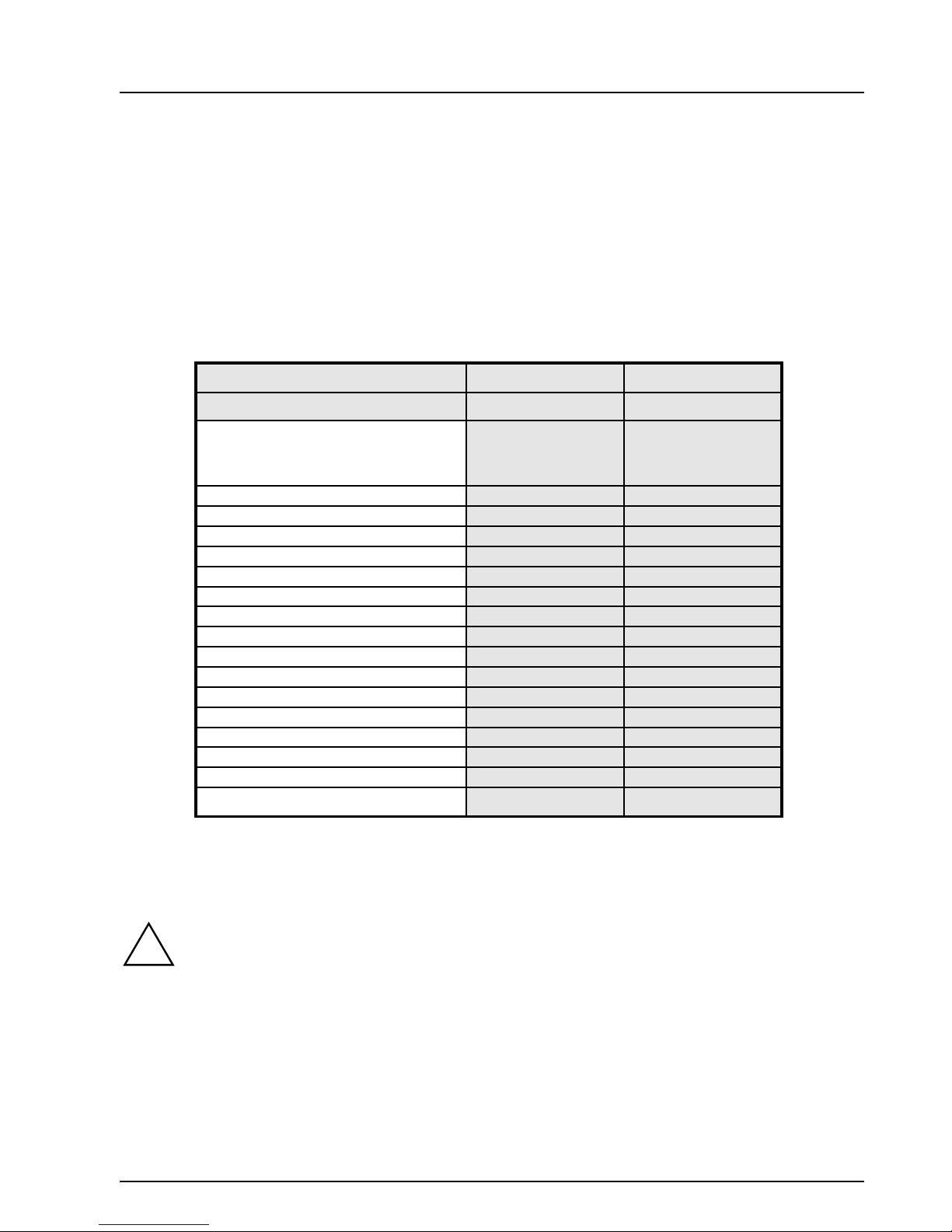
1 Features
Function Version Version
Processor Intel PentiumII,
Chipset Intel 440LX Intel 440EX
AGP connector X X
Wake on LAN (WOL) connector X USB X X
IrDA connector X Chipcard reader X Keyboard on X BIOS Fax - Quiet Boot X X
DMI X X
Systemmonitoring X DIMM 3 2
Memory ECC Support X FAX On - PCI Slots* 4 4
ISA Slots* 3 3
Technical Manual for the D1085
"Drivers & Utility" CD
D1085-A D1085-E
233 - 333 MHz
Intel Celeron
. For detailed information please
and the
Intel PentiumII,
233 - 333 MHz
Intel Celeron
Reference Manual
* = 1 PCI/ISA slot is shared
2 Mechanics
Computer mainboards and components contain very delicate IC chips. To protect
!
A26361-D1085-Z180-2-7619 Page 1
them against damage caused from electric static, you have to follow some
precautions:
•
Unplug your computer when you work inside.
•
Hold components by the edge, don’t touch their leads.
•
Use a grounded wrist strap.
Place the mainboard and the components on a grounded antistatic pad whenever
you work outside the computer.
Once you have installed the system board, you should remove the battery
protection (i.e. the thin plastic plate between battery and contact spring).
Page 2

Additional Technical Manual
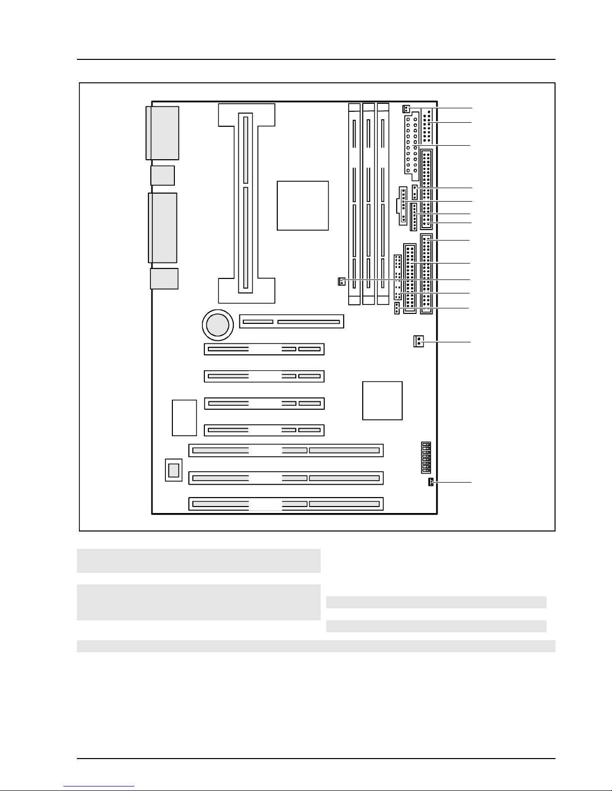
2.1 Layout
ATX 12’’ x 7,3’’ (305 mm x 185,4 mm)
Some of the following connectors are optional and may therefore not be included on your
mainboard.
3 2 1
1
2
1 = Serial port 2
2 = Serial port 1
3 = PS/2 mouse port
3
45 6
4 = PS/2 keyboard port
5 = Parallel port
6 = USB ports
PCI 4
PCI 3
PCI 2
PCI 1
ISA 3
ISA 2
ISA 1
Page 2 A26361-D1085-Z180-2-7619
Page 3
Additional Technical Manual
1
2
3
3 2 1
4
5
6
7
8
9
10
11
12
1 = System fan
2 = Chipcard reader
3 = Power supply
4 = Infrared receiver (IrDA)
5 = Cover detection
6 = Power supply monitor
7 = IDE drives 3 and 4 (secondary)
PCI 4
PCI 3
PCI 2
PCI 1
ISA 3
ISA 2
ISA 1
13
14
8 = IDE drives 1 and 2 (primary)
9 = Floppy disk drive
10 = Processor fan
11 = Control panel
12 = Intrusion plug
13 = Power On
14 = Wake-up on LAN
The connectors marked do not have to be present on the system board.
A26361-D1085-Z180-2-7619 Page 3
Page 4
Additional Technical Manual
2.2 Assembling Slot 1
Before inserting the CPU, you have to assembly the including stabilisators. Please be
i
carefully to avoid a damage of the mainboard.
2.3 Connectors, DIP-Switch, Jumpers
Some of the following connectors are optional!
!
2.3.1 Power supply ATX connector
Pin
11 + 3.3V 1 + 3.3V
12 - 12V 2 + 3.3V
13 GND 3 GND
14 PS on (low
15 GND 5 GND
16 GND 6 + 5V
17 GND 7 GND
18 - 5V 8 Powergood (high
19 + 5V 9 + 5V SB
20 + 5V 10 + 12V
Signal Pin Signal
4 + 5V
asserted)
asserted)
2.3.2 Power control connector
Pin Signal
1 Monitor on
2 SV FAN off request (low asserted)
3 SV FAN full on (low asserted)
4 SV FAN pulse
5 SMB CLK
6 SMB DATA
7 VCC EEPROM
8 GND
Pin 1Pin 11
Pin 1
Page 4 A26361-D1085-Z180-2-7619
Page 5
Additional Technical Manual
2.3.3 Power on switch connector
Pin Signal
1 GND
2 Power on pulse (low asserted)
2.3.4 Wake on LAN (WOL) connector
Pin Signal
1 + 5 V SB
2 GND
3 Wake pulse (high asserted)
2.3.5 CPU-FAN connector
Pin Signal
1 GND
2 FAN power supply
3 FAN sense
Pin 1
(stuffing option)
Pin 1
Pin 1
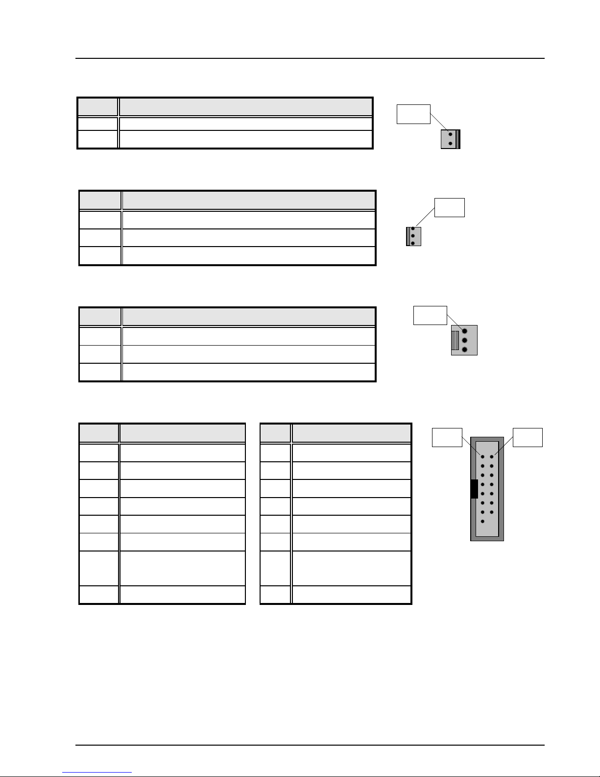
2.3.6 Internal serial port 1 for chip card reader
Pin Signal Pin Signal
1 DCD 2 (low asserted) 2 DSR 2 (low asserted)
3 SIN 2 (high asserted) 4 RTS 2 (low asserted)
5 SOUT 2 (high asserted) 6 CTS 2 (low asserted)
7 DTR 2 (low asserted) 8 PC_ON_Strobe
9 GND 10 VCC SB
11 12 VCC
13 RESETDRV
(high asserted)
15 GND 16 Key
14 GND
Pin 1 Pin 2
A26361-D1085-Z180-2-7619 Page 5
Page 6

2.2.7 Internal infrared (IrDA) connector
Additional Technical Manual
Pin Signal
1 VCCHELP
2 Key
3 IRDA_RX
4 GND
5 IRDA_TX
2.2.8 Internal speaker connector
Pin Signal
1 VCC
2 GND
3 Key
4 Speaker output
2.3.9 System management SM-BUS
Pin 1
Pin 1
Pin Signal
1 VCC
2 SM Clock
3
4 GND
SM Data
Pin 1
Page 6 A26361-D1085-Z180-2-7619
Page 7

Additional Technical Manual
2.3.10Front panel connector 1
Pin Signal Pin Signal
1 Boot Lock
2 Speaker
(high asserted)
3 Stand By LED
4 Key
(high asserted)
5 Key 6 GND
7 Power On LED
8 VCC
(high asserted)
9 Speaker 10 Key Pin
11 Power On &
12 Key
Stand By LED
(low asserted)
13 Message LED
14 Key
(high asserted)
15 Message LED
16 Key Pin
(low asserted)
17 Key 18 Key
19 VCC 20 Key
21 HD LED
22 Key
(low asserted)
23 Sleep Button
24 Not connected
(low asserted)
25 Power Button
(low asserted)
27 Sleep Button
(low asserted)
29 Reset Button
26 SCSI LED
(low asserted)
28 SCSI LED
(low asserted)
30 Not connected
(low asserted)
Pin 1 Pin 2
A26361-D1085-Z180-2-7619 Page 7
Page 8

2.3.11PCI-IDE Connector
Pin Signal Pin Signal
1 Reset Drive 2 GND
3 Data 7 4 Data 8
5 Data 6 6 Data 9
7 Data 5 8 Data 10
9 Data 4 10 Data 11
11 Data 3 12 Data 12
13 Data 2 14 Data 13
15 Data 1 16 Data 14
17 Data 0 18 Data 15
19 GND 20 Key
21 DRQ 22 GND
23 I/O Write 24 GND
Additional Technical Manual
25 I/O Read 26 GND
27 IORDY 28 N.C.
29 DACK 30 GND
31 IRQ 32 N.C.
33 ADR 1 34 N.C.
35 ADR 0 36 ADR 2
37 Chip Select 1 38 Chip Select 3
39 IDE-LED 40 GND
2.3.12AUX Audio IN Connector (e. g. MPEG, TV-Cards)
Pin Signal
1 GND
2 MPEG Audio In LEFT
3 GND
4 MPEG Audio In RIGHT
Pin 1
Pin 1
Page 8 A26361-D1085-Z180-2-7619
Page 9

Additional Technical Manual
2.3.13Infrared Connector
Pin Signal
1 VCC
2 key
3 IRDA_RX
4 GND
5 IRDA_TX
2.3.14Front Panel Connector 1
Pin Signal
1 Boot Lock
2 + Standby LED
3 Key
4 + Power LED
5 Key
6 - Standby/ Power LED
7 Keylock
Pin 1
Pin 1
8 GND
9 Key
10 + HD LED
11 HD LED
12 HD LED
A26361-D1085-Z180-2-7619 Page 9
Page 10

Additional Technical Manual
2.3.15Configuration SWITCH-Block (DIP-Switch)
For Frequency selection, Reserved, Password clear, Recovery and Floppy write.
Function SW1
SKP
Password Skip On x x x x x x x
Off Off x x x x x x x
Recovery BIOS x On x x x x x x
Off x Off x x x x x x
Floppy Write Protect x x On x x x x x
Off x x Off x x x x x
Reserved x x x On x x x x
Reserved x x x Off x x x x
Recovering System BIOS - switch 2
Switch 2 enables recovery of the old system BIOS after an attempt to update has failed. To restore
the old system BIOS you need a Flash BIOS Diskette (call customer service).
on
off
The System BIOS executes from floppy drive A: and restores the System BIOS on
the system board.
The System BIOS is started from the system board (default setting).
SW2
RCV
SW3
FWP
SW4
RES
SW5
CF1
SW6
CF2
SW7
CF3
SW8
CF4
Write protection for floppy disks - switch 3
Switch 3 is used to define whether floppy disks can be written or deleted in the floppy disk drive. To
write and delete floppy disks, the write -protection in
the field
on
off
Diskette Write
The floppy disk drive is write-protected.
Read, write and delete floppy disks is possible (default setting).
must be set to
Enabled
).
BIOS setup
must be disabled (in menu
Security
,
Page 10 A26361-D1085-Z180-2-7619
Page 11

Additional Technical Manual
Clock speed - switch 5, 6, 7 and 8
The switches may only be set as specified in the table below for the particular Pentium II
!
Pentium II with 66 MHz host bus frequency
Processor switch 5 switch 6 switch 7 switch 8
233 MHz off off on on
266 MHz on on off on
300 MHz off on off on
333 MHz on off off on
used.
This system board you may use with processors with a host bus frequency of 66 MHz
only.
Don't use processors with a host bus frequency of 100 MHz.
2.3.16PCI-SLOT Configuration and Placement
PCI-Slot IDSEL Device number
PCI-Slot 1 ADR 23 12 h
PCI-Slot 2 ADR 24 13 h
PCI-Slot 3 ADR 25 14 h
PCI-Slot 4 ADR 26 15 h
2.4 Power Requirements (Power Supply)
Source Voltage Max. Variation Max. Current
SV + 5.0 V +/- 5 % 15A
SV - 5 V +/- 5 % 100mA
SV + 12 V +/- 10 % 300mA
SV - 12 V +/- 10 % 100mA
SV + 3,3 V +/- 5 % 4 A
SV + 5.0 V (aux) +/- 5 % 500mA
−
ATX-capable
A26361-D1085-Z180-2-7619 Page 11
Page 12

Additional Technical Manual
3 Installing drivers and utilities; documentation
Insert the "Drivers & Utilities" CD.
When the
Select the language in which you want to operate the user interface.
Select
Here you will find the required drivers, utilities and the additional documentation.
For the following components, install the software offered to you in the HTML interface:
You will find the description for the Mainboard D1085 under “Documentation” > Technical
Manual (You may have to install the Acrobat Reader - Software on the CD-ROM (path:
utls/acrobat) before reading!)
For more details please read the according readme.txt files
DeskStart
Scenic Pro
−
Harddisk-Controller: PIIX4-Support
−
Updates: USB-Support
window appears, select
and then select e. g.
Explore the CD via HTML
Windows 95
.
.
4 Upgrades
4.1 Main Memory
Further information is given in the main technical manual.
For correct functionality of this mainboard we recommend the usage of the following DIMM-
Modules.
For upgrades of the following list, please ask your local dealer.
16MB DIMM SDRAM, 2Mx64
Producer Part.-No
Samsung KMM366S203BTN-G0 und -G2
32MB DIMM SDRAM, 4Mx64
Producer Part.-No
NEC MC-454AD644F-A67
Samsung KMM366S403BTN-G0 und -G2
HYUNDAI HYM7V64400TFG-10
Page 12 A26361-D1085-Z180-2-7619
Page 13

Additional Technical Manual
32MB DIMM SDRAM, 4Mx72
Producer Part.-No
Goldstar GMM2734233BLTG-10K
Hyundai HYM7V72A400TFG-10
Samsung KMM374S4030BTN-G2
64MB DIMM SDRAM, 8Mx64
Producer Part.-No
NEC MC-458CB644F-A10
Samsung KMM366S823BTL-G0
64MB DIMM SDRAM, 8Mx72
Producer Part.-No
NEC MC458CA724F-A10
Samsung KMM374S823BTL-G0
128MB DIMM SDRAM, 16Mx64
Producer Part.-No
NEC MC-4516CD644F-A10
128MB DIMM SDRAM, 16Mx72
Producer Part.-No
NEC MC-4516CC724F-A10
A26361-D1085-Z180-2-7619 Page 13
Page 14

Additional Technical Manual
Contents
Introduction.......................................................................................................................................1
1 Features.........................................................................................................................................1
2 Mechanics......................................................................................................................................1
2.1 Layout.........................................................................................................................................2
2.2 Assembling Slot 1........................................................................................................................4
2.3 Connectors, DIP-Switch, Jumpers...............................................................................................4
2.3.1 Power supply ATX connector............................................................................................4
2.3.2 Power control connector...................................................................................................4
2.3.3 Power on switch connector...............................................................................................5
2.3.4 Wake on LAN (WOL) connector (stuffing option)..............................................................5
2.3.5 CPU-FAN connector.........................................................................................................5
2.3.6 Internal serial port 1 for chip card reader..........................................................................5
2.2.7 Internal infrared (IrDA) connector......................................................................................6
2.2.8 Internal speaker connector...............................................................................................6
2.3.9 System management SM-BUS.........................................................................................6
2.3.10 Front panel connector 1..................................................................................................7
2.3.11 PCI-IDE Connector.........................................................................................................8
2.3.12 AUX Audio IN Connector (e. g. MPEG, TV-Cards).........................................................8
2.3.13 Infrared Connector..........................................................................................................9
2.3.14 Front Panel Connector 1.................................................................................................9
2.3.15 Configuration SWITCH-Block (DIP-Switch)...................................................................10
2.3.16 PCI-SLOT Configuration and Placement......................................................................11
2.4 Power Requirements (Power Supply)........................................................................................11
3 Installing drivers and utilities; documentation................................................................................12
4 Upgrades......................................................................................................................................12
4.1 Main Memory.............................................................................................................................12
A26361-D1085-Z180-2-7619
Page 15

Additional Technical Manual
A26361-D1085-Z180-2-7619
System board D1085
Additional Technical Manual
October 1998 edition
Copyright Siemens AG September 1998.
A26361-D1085-Z180-2-7619
 Loading...