

Siemens SIMATIC S7-300 Series, CPU 314 IFM, CPU 315, CPU 315-2 DP, CPU 316-2 DP Reference Manual
...Page 1
DATASHEET
6ES7314-5AE03-0AB0
SIEMENS
OTHER SYMBOLS:
RGB ELEKTRONIKA AGACIAK CIACIEK
SPÓŁKA JAWNA
Jana Dlugosza 2-6 Street
51-162 Wrocław
Poland
biuro@rgbelektronika.pl
+48 71 325 15 05
www.rgbautomatyka.pl
www.rgbelektronika.pl
www.rgbelektronika.pl
www.rgbautomatyka.pl
Page 2
YOUR
PARTNER IN
MAINTENANCE
Repair this product with RGB ELEKTRONIKA
LINEAR
ENCODERS
ENCODERS
SERVO AMPLIFIERS
CNC
MACHINES
OUR SERVICES
PLC
SYSTEMS
CNC
CONTROLS
ORDER A DIAGNOSIS
INDUSTRIAL
COMPUTERS
POWER
SUPPLIERS
∠
MOTORS
SERVO
DRIVERS
At our premises in Wrocław, we have a fully equipped servicing facility. Here we perform all the repair
works and test each later sold unit. Our trained employees, equipped with a wide variety of tools and
having several testing stands at their disposal, are a guarantee of the highest quality service.
Buy this product at RGB AUTOMATYKA
OPERATOR
PANELS
BUY
∠
Page 3
Preface, Contents
SIMATIC
PLC S7-300,
CPU Specifications CPU 312 IFM
to CPU 318-2 DP
Reference Manual
CPUs
CPU 31x-2 as DP Master/DP
Slave and Direct Communication
Cycle and Reaction times
CPU Function, depending on
CPU and STEP 7 Version
Tips and Tricks
Appendix
Standards, Certificates and
Approvals
Dimensioned Drawings
List of Abbreviations
1
2
3
4
5
A
B
C
This manual is part of the documentation
package with the order number
6ES7398-8FA10-8BA0
Edition 10/2001
A5E00111190-01
This documentation can no longer be ordered under
the given number!
Glossary, Index
Page 4
Safety Guidelines
This manual contains notices intended to ensure personal safety, as well as to protect the products and
connected equipment against damage. These notices are highlighted by the symbols shown below and
graded according to severity by the following texts:
Danger
!
indicates that death, severe personal injury or substantial property damage will result if proper precautions
are not taken.
Warning
!
indicates that death, severe personal injury or substantial property damage can result if proper
precautions are not taken.
Caution
!
indicates that minor personal injury can result if proper precautions are not taken.
Caution
indicates that property damage can result if proper precautions are not taken.
Notice
draws your attention to particularly important information on the product, handling the product, or to a
particular part of the documentation.
Qualified Personnel
Only qualified personnel should be allowed to install and work on this equipment. Qualified persons are
defined as persons who are authorized to commission, to ground and to tag circuits, equipment, and
systems in accordance with established safety practices and standards.
Correct Usage
Note the following:
Warning
!
Trademarks
The reproduction, transmission or use of this document or its
contents is not permitted without express written authority.
Offenders will be liable for damages. All rights, including rights
created by patent grant or registration of a utility model or
design, are reserved.
Siemens AG
Bereich Automatisierungs- und Antriebstechnik
Geschaeftsgebiet Industrie-Automatisierungssysteme
Postfach 4848, D- 90327 Nuernberg
Index-2
Siemens Aktiengesellschaft A5E00111190
This device and its components may only be used for the applications described in the catalog or the
technical description, and only in connection with devices or components from other manufacturers which
have been approved or recommended by Siemens.
This product can only function correctly and safely if it is transported, stored, set up, and installed
correctly, and operated and maintained as recommended.
SIMATIC, SIMA TIC HMI and SIMATIC NET are registered trademarks of SIEMENS AG.
Third parties using for their own purposes any other names in this document which refer to trademarks
might infringe upon the rights of the trademark owners.
Disclaim of LiabilityCopyright W Siemens AG 2001 All rights reserved
We have checked the contents of this manual for agreement
with the hardware and software described. Since deviations
cannot be precluded entirely, we cannot guarantee full
agreement. However, the data in this manual are reviewed
regularly and any necessary corrections included in
subsequent editions. Suggestions for improvement are
welcomed.
Siemens AG 2001
Technical data subject to change.
PLC S7-300, CPU Specifications CPU 312 IFM to CPU 318-2 DP
A5E00111190-01
Page 5
Preface
Purpose of the Manual
This manual gives you a brief overview of 312 IFM to 318-2 CPUS in an S7-300.
You can look up information on how to operate the system, its functions and
technical data of the CPUs.
Essential know-how
General knowledge of automation technology is required for comprehension of this
Manual. You should also be acquainted with basic STEP 7 software as described
in your Programming with STEP 7 V 5.1 Manual.
PLC S7-300, CPU Specifications CPU 312 IFM to CPU 318-2 DP
A5E00111190-01
iii
Page 6
Preface
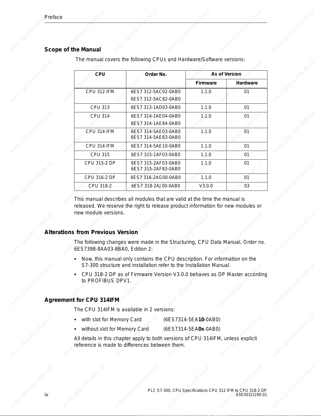
Scope of the Manual
The manual covers the following CPUs and Hardware/Software versions:
CPU Order No.
CPU 312 IFM 6ES7 312-5AC02-0AB0
6ES7 312-5AC82-0AB0
CPU 313 6ES7 313-1AD03-0AB0 1.1.0 01
CPU 314 6ES7 314-1AE04-0AB0
6ES7 314-1AE84-0AB0
CPU 314 IFM 6ES7 314-5AE03-0AB0
6ES7 314-5AE83-0AB0
CPU 314 IFM 6ES7 314-5AE10-0AB0 1.1.0 01
CPU 315 6ES7 315-1AF03-0AB0 1.1.0 01
CPU 315-2 DP 6ES7 315-2AF03-0AB0
6ES7 315-2AF83-0AB0
CPU 316-2 DP 6ES7 316-2AG00-0AB0 1.1.0 01
CPU 318-2 6ES7 318-2AJ00-0AB0 V3.0.0 03
As of Version
Firmware Hardware
1.1.0 01
1.1.0 01
1.1.0 01
1.1.0 01
This manual describes all modules that are valid at the time the manual is
released. We reserve the right to release product information for new modules or
new module versions.
Alterations from Previous Version
The following changes were made in the Structuring, CPU Data Manual, Order no.
6ES7398-8AA03-8BA0, Edition 2:
Now, this manual only contains the CPU description. For information on the
S7-300 structure and installation refer to the Installation Manual.
CPU 318-2 DP as of Firmware Version V3.0.0 behaves as DP Master according
to PROFIBUS DPV1.
Agreement for CPU 314IFM
The CPU 314IFM is available in 2 versions:
with slot for Memory Card (6ES7314-5EA10-0AB0)
without slot for Memory Card (6ES7314-5EA0x-0AB0)
All details in this chapter apply to both versions of CPU 314IFM, unless explicit
reference is made to differences between them.
iv
PLC S7-300, CPU Specifications CPU 312 IFM to CPU 318-2 DP
A5E00111190-01
Page 7
Approbation, Standards and Approvals
The SIMATIC S7-300 series conforms to:
Requirements and criteria to IEC 61131, Part 2
CE labeling
– EC Guideline 73/23/EEC on Low Voltages
– EC Guideline 89/336/EEC on electromagnetic compatibility (EMC)
Canadian Standards Association: CSA C22.2 Number 142, tested (Process
Control Equipment)
Underwriters Laboratories, Inc.: UL 508 registered (Industrial Control
Equipment)
Underwriters Laboratories, Inc.: UL 508 (Industrial Control Equipment)
Factory Mutual Research: Approval Standard Class Number 3611
C-Tick Australia
Preface
PLC S7-300, CPU Specifications CPU 312 IFM to CPU 318-2 DP
A5E00111190-01
v
Page 8
Preface
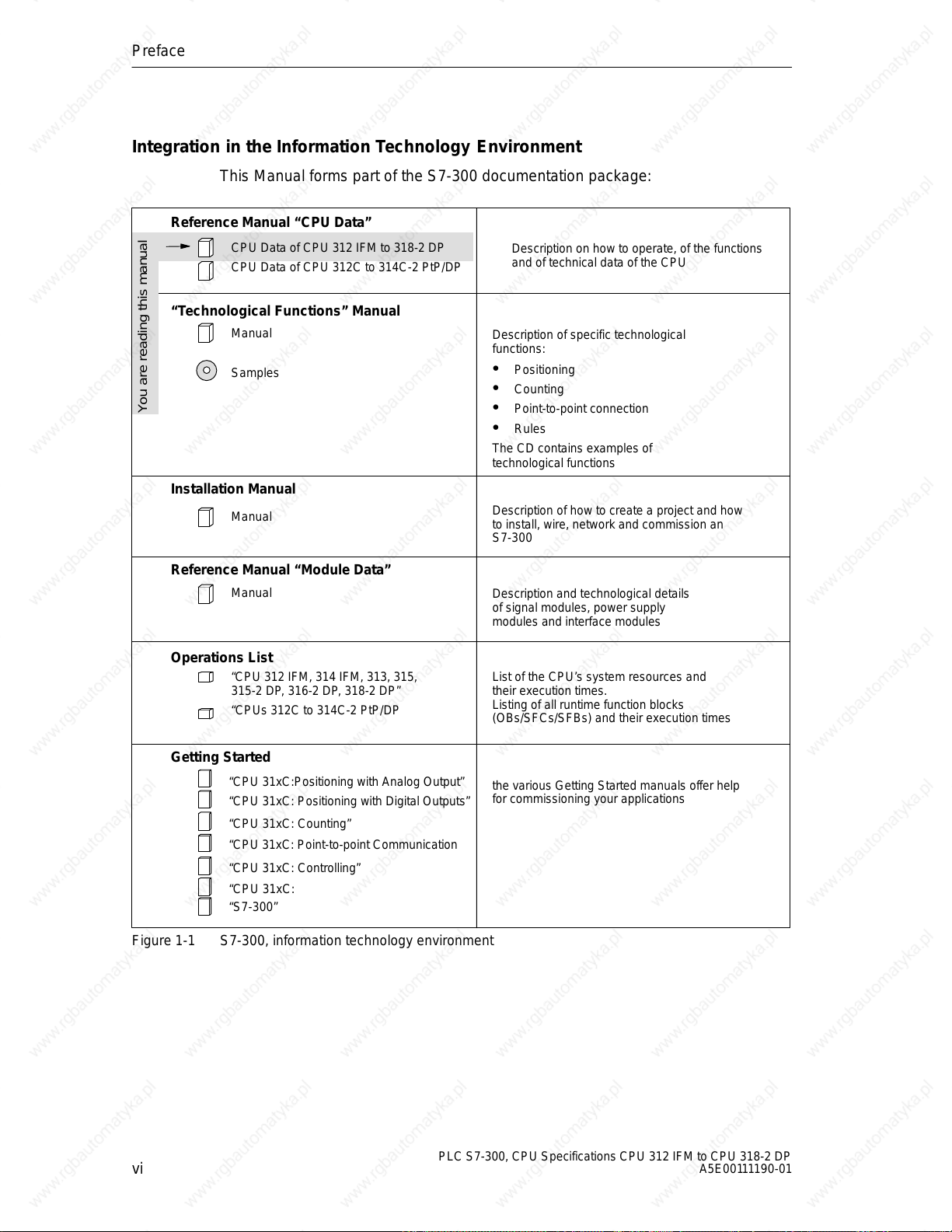
Integration in the Information Technology Environment
This Manual forms part of the S7-300 documentation package:
Reference Manual “CPU Data”
CPU Data of CPU 312 IFM to 318-2 DP
CPU Data of CPU 312C to 314C-2 PtP/DP
“Technological Functions” Manual
Manual
Samples
Description on how to operate, of the functions
and of technical data of the CPU
Description of specific technological
functions:
Positioning
Counting
You are reading this manual
Point-to-point connection
Rules
The CD contains examples of
technological functions
Installation Manual
Manual
Description of how to create a project and how
to install, wire, network and commission an
S7-300
Reference Manual “Module Data”
Manual
Operations List
“CPU 312 IFM, 314 IFM, 313, 315,
315-2 DP, 316-2 DP, 318-2 DP”
“CPUs 312C to 314C-2 PtP/DP
Getting Started
“CPU 31xC:Positioning with Analog Output”
“CPU 31xC: Positioning with Digital Outputs”
“CPU 31xC: Counting”
“CPU 31xC: Point-to-point Communication
“CPU 31xC: Controlling”
“CPU 31xC:
“S7-300”
Figure 1-1 S7-300, information technology environment
Description and technological details
of signal modules, power supply
modules and interface modules
List of the CPU’s system resources and
their execution times.
Listing of all runtime function blocks
(OBs/SFCs/SFBs) and their execution times
the various Getting Started manuals offer help
for commissioning your applications
vi
PLC S7-300, CPU Specifications CPU 312 IFM to CPU 318-2 DP
A5E00111190-01
Page 9
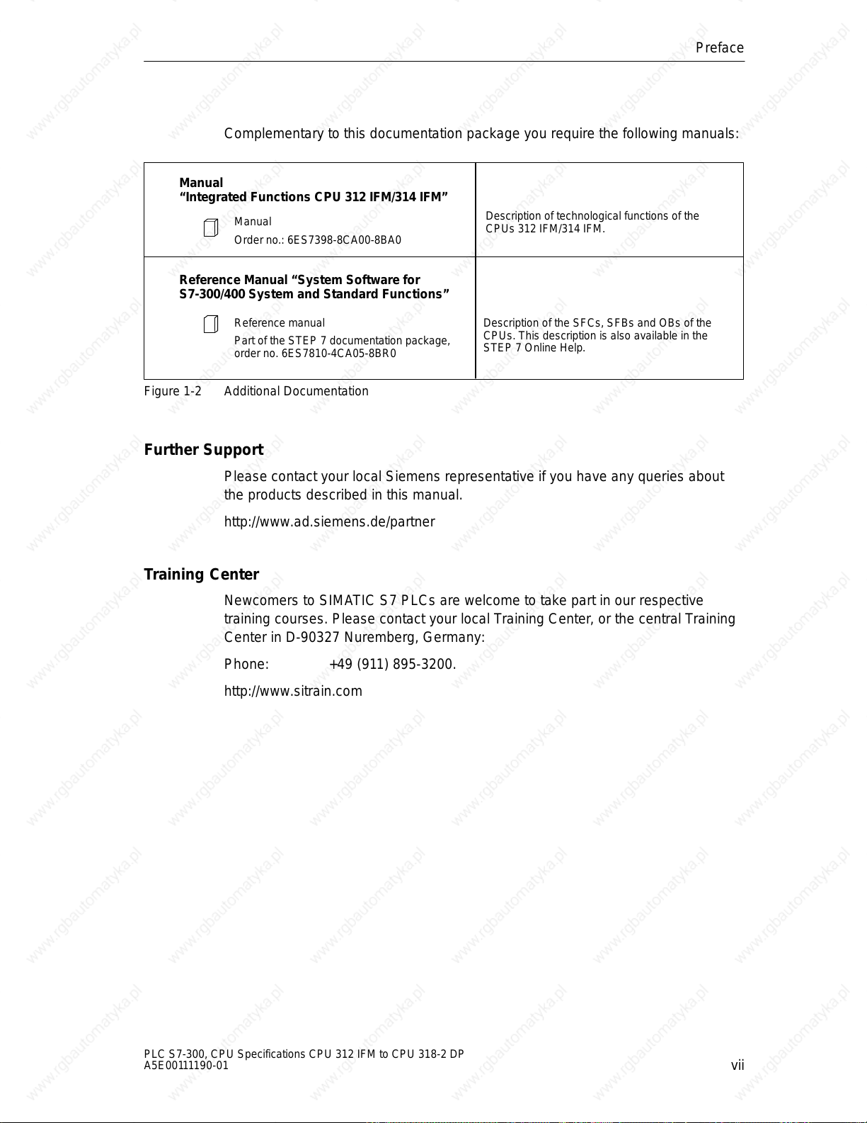
Complementary to this documentation package you require the following manuals:
Manual
“Integrated Functions CPU 312 IFM/314 IFM”
Manual
Order no.: 6ES7398-8CA00-8BA0
Reference Manual “System Software for
S7-300/400 System and Standard Functions”
Preface
Description of technological functions of the
CPUs 312 IFM/314 IFM.
Reference manual
Part of the STEP 7 documentation package,
order no. 6ES7810-4CA05-8BR0
Figure 1-2 Additional Documentation
Further Support
Please contact your local Siemens representative if you have any queries about
the products described in this manual.
http://www.ad.siemens.de/partner
Training Center
Newcomers to SIMATIC S7 PLCs are welcome to take part in our respective
training courses. Please contact your local Training Center, or the central Training
Center in D-90327 Nuremberg, Germany:
Phone: +49 (911) 895-3200.
http://www.sitrain.com
Description of the SFCs, SFBs and OBs of the
CPUs. This description is also available in the
STEP 7 Online Help.
PLC S7-300, CPU Specifications CPU 312 IFM to CPU 318-2 DP
A5E00111190-01
vii
Page 10
Preface
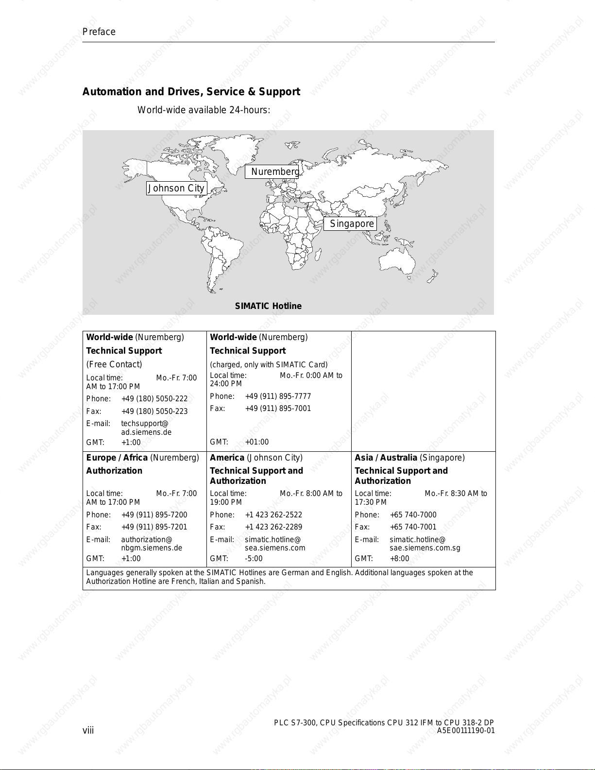
Automation and Drives, Service & Support
World-wide available 24-hours:
Nuremberg
Johnson City
SIMATIC Hotline
Singapore
World-wide (Nuremberg)
T echnical Support
(Free Contact)
Local time: Mo.-Fr. 7:00
AM to 17:00 PM
Phone: +49 (180) 5050-222
Fax: +49 (180) 5050-223
E-mail: techsupport@
ad.siemens.de
GMT: +1:00
Europe / Africa (Nuremberg)
Authorization
Local time: Mo.-Fr. 7:00
AM to 17:00 PM
Phone: +49 (911) 895-7200
Fax: +49 (911) 895-7201
E-mail: authorization@
nbgm.siemens.de
GMT: +1:00
Languages generally spoken at the SIMATIC Hotlines are German and English. Additional languages spoken at the
Authorization Hotline are French, Italian and Spanish.
World-wide (Nuremberg)
T echnical Support
(charged, only with SIMATIC Card)
Local time: Mo.-Fr. 0:00 AM to
24:00 PM
Phone: +49 (911) 895-7777
Fax: +49 (911) 895-7001
GMT: +01:00
America (Johnson City)
Technical Support and
Authorization
Local time: Mo.-Fr. 8:00 AM to
19:00 PM
Phone: +1 423 262-2522
Fax: +1 423 262-2289
E-mail: simatic.hotline@
sea.siemens.com
GMT: -5:00
Asia / Australia (Singapore)
Technical Support and
Authorization
Local time: Mo.-Fr. 8:30 AM to
17:30 PM
Phone: +65 740-7000
Fax: +65 740-7001
E-mail: simatic.hotline@
sae.siemens.com.sg
GMT: +8:00
viii
PLC S7-300, CPU Specifications CPU 312 IFM to CPU 318-2 DP
A5E00111190-01
Page 11
SIMATIC Documentation on the Internet
Documentation is available free of charge on the Internet under:
http://www.ad.siemens.de/support
Please use the Knowledge Manager offered at these locations for quick location of
your required documentation. Our Internet Forum offers a “Documentation”
conferencing room for your questions and solution proposals.
http://www.ad.siemens.de/support
Service & Support on the Internet
As a supplement to our provided documentation we offer our complete know-how
base on the Internet.
http://www.ad.siemens.de/support
There you will find:
Up-to-date product information (News), FAQs (Frequently Asked Questions),
Downloads, Tips and Tricks.
Preface
Our Newsletter always offers you the most up-to-date information on your
products.
The Knowledge Manager finds the right documents for you.
Users and specialists across the globe share their experiences in our Forum.
Your local service partner for Automation & Drives is found in our Service
Partner Database.
Information relating to on–site Service, repairs, spare parts and lots more is
available to you under the topic “Service”.
PLC S7-300, CPU Specifications CPU 312 IFM to CPU 318-2 DP
A5E00111190-01
ix
Page 12

Preface
x
PLC S7-300, CPU Specifications CPU 312 IFM to CPU 318-2 DP
A5E00111190-01
Page 13
Contents
1 CPUs
1.1 Control and Display Elements 1-2 . . . . . . . . . . . . . . . . . . . . . . . . . . . . . . . . . . . . .
1.1.1 Status and Fault Displays 1-3 . . . . . . . . . . . . . . . . . . . . . . . . . . . . . . . . . . . . . . . .
1.1.2 Mode Selector Switch 1-4 . . . . . . . . . . . . . . . . . . . . . . . . . . . . . . . . . . . . . . . . . . . .
1.1.3 Backup battery/accumulator 1-5 . . . . . . . . . . . . . . . . . . . . . . . . . . . . . . . . . . . . . .
1.1.4 Memory card 1-6 . . . . . . . . . . . . . . . . . . . . . . . . . . . . . . . . . . . . . . . . . . . . . . . . . . .
1.1.5 MPI and PROFIBUS-DP Interface 1-7 . . . . . . . . . . . . . . . . . . . . . . . . . . . . . . . . .
1.1.6 Clock and Runtime Meter 1-10 . . . . . . . . . . . . . . . . . . . . . . . . . . . . . . . . . . . . . . . . .
1.2 Communication Options of the CPU 1-11 . . . . . . . . . . . . . . . . . . . . . . . . . . . . . . .
1.3 Test Functions and Diagnostics 1-19 . . . . . . . . . . . . . . . . . . . . . . . . . . . . . . . . . . .
1.3.1 Testing Functions 1-19 . . . . . . . . . . . . . . . . . . . . . . . . . . . . . . . . . . . . . . . . . . . . . . .
1.3.2 Diagnostics with LED Display 1-22 . . . . . . . . . . . . . . . . . . . . . . . . . . . . . . . . . . . . .
1.3.3 Diagnostics with STEP 7 1-22 . . . . . . . . . . . . . . . . . . . . . . . . . . . . . . . . . . . . . . . . .
1.4 CPUs - Technical Specifications 1-24 . . . . . . . . . . . . . . . . . . . . . . . . . . . . . . . . . . .
1.4.1 CPU 312 IFM 1-25 . . . . . . . . . . . . . . . . . . . . . . . . . . . . . . . . . . . . . . . . . . . . . . . . . . .
1.4.2 CPU 313 1-37 . . . . . . . . . . . . . . . . . . . . . . . . . . . . . . . . . . . . . . . . . . . . . . . . . . . . . . .
1.4.3 CPU 314 1-40 . . . . . . . . . . . . . . . . . . . . . . . . . . . . . . . . . . . . . . . . . . . . . . . . . . . . . . .
1.4.4 CPU 314IFM 1-43 . . . . . . . . . . . . . . . . . . . . . . . . . . . . . . . . . . . . . . . . . . . . . . . . . . .
1.4.5 CPU 315 1-60 . . . . . . . . . . . . . . . . . . . . . . . . . . . . . . . . . . . . . . . . . . . . . . . . . . . . . . .
1.4.6 CPU 315-2 DP 1-63 . . . . . . . . . . . . . . . . . . . . . . . . . . . . . . . . . . . . . . . . . . . . . . . . . .
1.4.7 CPU 316-2 DP 1-66 . . . . . . . . . . . . . . . . . . . . . . . . . . . . . . . . . . . . . . . . . . . . . . . . . .
1.4.8 CPU 318-2 1-69 . . . . . . . . . . . . . . . . . . . . . . . . . . . . . . . . . . . . . . . . . . . . . . . . . . . . .
2 CPU 31x-2 as DP Master/DP Slave and Direct Communication
2.1 Information on DPV1 Functionality 2-2 . . . . . . . . . . . . . . . . . . . . . . . . . . . . . . . . .
2.2 DP Address Areas of the CPUs 31x-2 2-4 . . . . . . . . . . . . . . . . . . . . . . . . . . . . . .
2.3 CPU 31x-2 as DP Master 2-5 . . . . . . . . . . . . . . . . . . . . . . . . . . . . . . . . . . . . . . . . .
2.4 Diagnostics of the CPU 31x-2 as DP Master 2-6 . . . . . . . . . . . . . . . . . . . . . . . .
2.5 CPU 31x-2 as DP-Slave 2-13 . . . . . . . . . . . . . . . . . . . . . . . . . . . . . . . . . . . . . . . . . .
PLC S7-300, CPU Specifications CPU 312 IFM to CPU 318-2 DP
A5E00111190-01
xi
Page 14
Contents
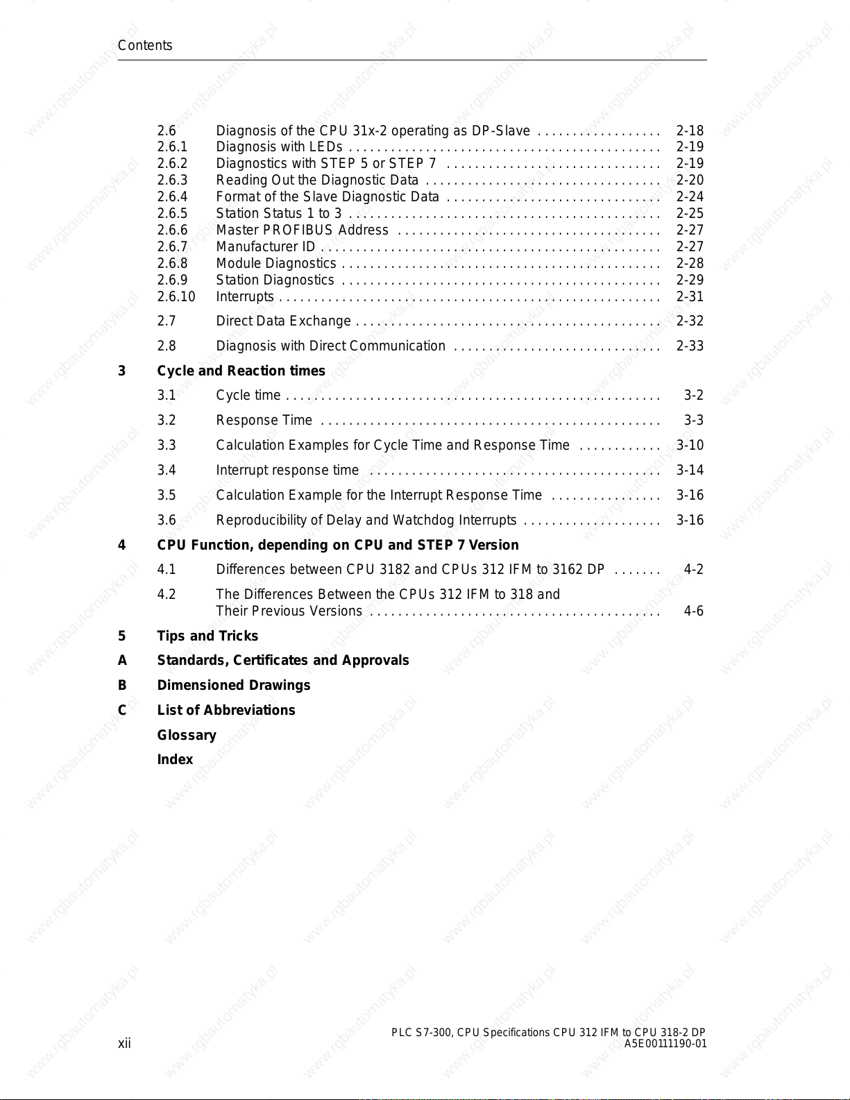
2.6 Diagnosis of the CPU 31x-2 operating as DP-Slave 2-18 . . . . . . . . . . . . . . . . . .
2.6.1 Diagnosis with LEDs 2-19 . . . . . . . . . . . . . . . . . . . . . . . . . . . . . . . . . . . . . . . . . . . . .
2.6.2 Diagnostics with STEP 5 or STEP 7 2-19 . . . . . . . . . . . . . . . . . . . . . . . . . . . . . . .
2.6.3 Reading Out the Diagnostic Data 2-20 . . . . . . . . . . . . . . . . . . . . . . . . . . . . . . . . . .
2.6.4 Format of the Slave Diagnostic Data 2-24 . . . . . . . . . . . . . . . . . . . . . . . . . . . . . . .
2.6.5 Station Status 1 to 3 2-25 . . . . . . . . . . . . . . . . . . . . . . . . . . . . . . . . . . . . . . . . . . . . .
2.6.6 Master PROFIBUS Address 2-27 . . . . . . . . . . . . . . . . . . . . . . . . . . . . . . . . . . . . . .
2.6.7 Manufacturer ID 2-27 . . . . . . . . . . . . . . . . . . . . . . . . . . . . . . . . . . . . . . . . . . . . . . . . .
2.6.8 Module Diagnostics 2-28 . . . . . . . . . . . . . . . . . . . . . . . . . . . . . . . . . . . . . . . . . . . . . .
2.6.9 Station Diagnostics 2-29 . . . . . . . . . . . . . . . . . . . . . . . . . . . . . . . . . . . . . . . . . . . . . .
2.6.10 Interrupts 2-31 . . . . . . . . . . . . . . . . . . . . . . . . . . . . . . . . . . . . . . . . . . . . . . . . . . . . . . .
2.7 Direct Data Exchange 2-32 . . . . . . . . . . . . . . . . . . . . . . . . . . . . . . . . . . . . . . . . . . . .
2.8 Diagnosis with Direct Communication 2-33 . . . . . . . . . . . . . . . . . . . . . . . . . . . . . .
3 Cycle and Reaction times
3.1 Cycle time 3-2 . . . . . . . . . . . . . . . . . . . . . . . . . . . . . . . . . . . . . . . . . . . . . . . . . . . . . .
3.2 Response Time 3-3 . . . . . . . . . . . . . . . . . . . . . . . . . . . . . . . . . . . . . . . . . . . . . . . . .
3.3 Calculation Examples for Cycle Time and Response Time 3-10 . . . . . . . . . . . .
3.4 Interrupt response time 3-14 . . . . . . . . . . . . . . . . . . . . . . . . . . . . . . . . . . . . . . . . . .
3.5 Calculation Example for the Interrupt Response Time 3-16 . . . . . . . . . . . . . . . .
3.6 Reproducibility of Delay and Watchdog Interrupts 3-16 . . . . . . . . . . . . . . . . . . . .
4 CPU Function, depending on CPU and STEP 7 Version
4.1 Differences between CPU 3182 and CPUs 312 IFM to 3162 DP 4-2 . . . . . . .
4.2 The Differences Between the CPUs 312 IFM to 318 and
Their Previous Versions 4-6 . . . . . . . . . . . . . . . . . . . . . . . . . . . . . . . . . . . . . . . . . .
5 Tips and Tricks
A Standards, Certificates and Approvals
B Dimensioned Drawings
C List of Abbreviations
Glossary
Index
xii
PLC S7-300, CPU Specifications CPU 312 IFM to CPU 318-2 DP
A5E00111190-01
Page 15
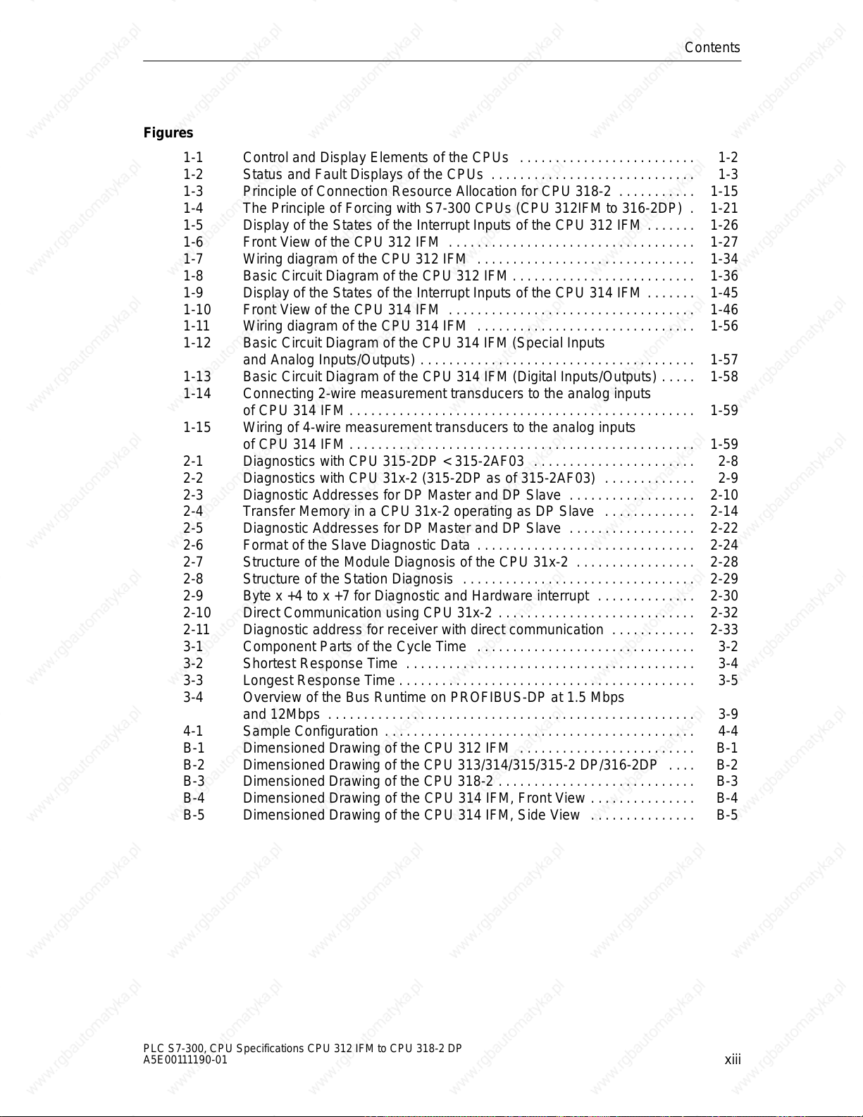
Figures
1-1 Control and Display Elements of the CPUs 1-2 . . . . . . . . . . . . . . . . . . . . . . . . .
1-2 Status and Fault Displays of the CPUs 1-3 . . . . . . . . . . . . . . . . . . . . . . . . . . . . .
1-3 Principle of Connection Resource Allocation for CPU 318-2 1-15 . . . . . . . . . . .
1-4 The Principle of Forcing with S7-300 CPUs (CPU 312IFM to 316-2DP) 1-21 .
1-5 Display of the States of the Interrupt Inputs of the CPU 312 IFM 1-26 . . . . . . .
1-6 Front View of the CPU 312 IFM 1-27 . . . . . . . . . . . . . . . . . . . . . . . . . . . . . . . . . . .
1-7 Wiring diagram of the CPU 312 IFM 1-34 . . . . . . . . . . . . . . . . . . . . . . . . . . . . . . .
1-8 Basic Circuit Diagram of the CPU 312 IFM 1-36 . . . . . . . . . . . . . . . . . . . . . . . . . .
1-9 Display of the States of the Interrupt Inputs of the CPU 314 IFM 1-45 . . . . . . .
1-10 Front View of the CPU 314 IFM 1-46 . . . . . . . . . . . . . . . . . . . . . . . . . . . . . . . . . . .
1-11 Wiring diagram of the CPU 314 IFM 1-56 . . . . . . . . . . . . . . . . . . . . . . . . . . . . . . .
1-12 Basic Circuit Diagram of the CPU 314 IFM (Special Inputs
and Analog Inputs/Outputs) 1-57 . . . . . . . . . . . . . . . . . . . . . . . . . . . . . . . . . . . . . . .
1-13 Basic Circuit Diagram of the CPU 314 IFM (Digital Inputs/Outputs) 1-58 . . . . .
1-14 Connecting 2-wire measurement transducers to the analog inputs
of CPU 314 IFM 1-59 . . . . . . . . . . . . . . . . . . . . . . . . . . . . . . . . . . . . . . . . . . . . . . . . .
1-15 Wiring of 4-wire measurement transducers to the analog inputs
of CPU 314 IFM 1-59 . . . . . . . . . . . . . . . . . . . . . . . . . . . . . . . . . . . . . . . . . . . . . . . . .
2-1 Diagnostics with CPU 315-2DP < 315-2AF03 2-8 . . . . . . . . . . . . . . . . . . . . . . .
2-2 Diagnostics with CPU 31x-2 (315-2DP as of 315-2AF03) 2-9 . . . . . . . . . . . . .
2-3 Diagnostic Addresses for DP Master and DP Slave 2-10 . . . . . . . . . . . . . . . . . .
2-4 Transfer Memory in a CPU 31x-2 operating as DP Slave 2-14 . . . . . . . . . . . . .
2-5 Diagnostic Addresses for DP Master and DP Slave 2-22 . . . . . . . . . . . . . . . . . .
2-6 Format of the Slave Diagnostic Data 2-24 . . . . . . . . . . . . . . . . . . . . . . . . . . . . . . .
2-7 Structure of the Module Diagnosis of the CPU 31x-2 2-28 . . . . . . . . . . . . . . . . .
2-8 Structure of the Station Diagnosis 2-29 . . . . . . . . . . . . . . . . . . . . . . . . . . . . . . . . .
2-9 Byte x +4 to x +7 for Diagnostic and Hardware interrupt 2-30 . . . . . . . . . . . . . .
2-10 Direct Communication using CPU 31x-2 2-32 . . . . . . . . . . . . . . . . . . . . . . . . . . . .
2-11 Diagnostic address for receiver with direct communication 2-33 . . . . . . . . . . . .
3-1 Component Parts of the Cycle Time 3-2 . . . . . . . . . . . . . . . . . . . . . . . . . . . . . . .
3-2 Shortest Response Time 3-4 . . . . . . . . . . . . . . . . . . . . . . . . . . . . . . . . . . . . . . . . .
3-3 Longest Response Time 3-5 . . . . . . . . . . . . . . . . . . . . . . . . . . . . . . . . . . . . . . . . . .
3-4 Overview of the Bus Runtime on PROFIBUS-DP at 1.5 Mbps
and 12Mbps 3-9 . . . . . . . . . . . . . . . . . . . . . . . . . . . . . . . . . . . . . . . . . . . . . . . . . . . .
4-1 Sample Configuration 4-4 . . . . . . . . . . . . . . . . . . . . . . . . . . . . . . . . . . . . . . . . . . . .
B-1 Dimensioned Drawing of the CPU 312 IFM B-1 . . . . . . . . . . . . . . . . . . . . . . . . .
B-2 Dimensioned Drawing of the CPU 313/314/315/315-2 DP/316-2DP B-2 . . . .
B-3 Dimensioned Drawing of the CPU 318-2 B-3 . . . . . . . . . . . . . . . . . . . . . . . . . . . .
B-4 Dimensioned Drawing of the CPU 314 IFM, Front View B-4 . . . . . . . . . . . . . . .
B-5 Dimensioned Drawing of the CPU 314 IFM, Side View B-5 . . . . . . . . . . . . . . .
Contents
PLC S7-300, CPU Specifications CPU 312 IFM to CPU 318-2 DP
A5E00111190-01
xiii
Page 16
Contents
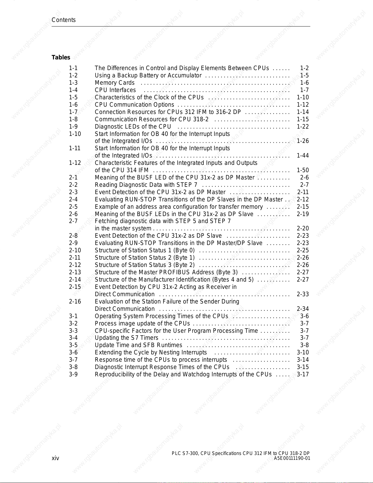
Tables
1-1 The Differences in Control and Display Elements Between CPUs 1-2 . . . . . .
1-2 Using a Backup Battery or Accumulator 1-5 . . . . . . . . . . . . . . . . . . . . . . . . . . . .
1-3 Memory Cards 1-6 . . . . . . . . . . . . . . . . . . . . . . . . . . . . . . . . . . . . . . . . . . . . . . . . .
1-4 CPU Interfaces 1-7 . . . . . . . . . . . . . . . . . . . . . . . . . . . . . . . . . . . . . . . . . . . . . . . .
1-5 Characteristics of the Clock of the CPUs 1-10 . . . . . . . . . . . . . . . . . . . . . . . . . . .
1-6 CPU Communication Options 1-12 . . . . . . . . . . . . . . . . . . . . . . . . . . . . . . . . . . . . .
1-7 Connection Resources for CPUs 312 IFM to 316-2 DP 1-14 . . . . . . . . . . . . . . .
1-8 Communication Resources for CPU 318-2 1-15 . . . . . . . . . . . . . . . . . . . . . . . . .
1-9 Diagnostic LEDs of the CPU 1-22 . . . . . . . . . . . . . . . . . . . . . . . . . . . . . . . . . . . . .
1-10 Start Information for OB 40 for the Interrupt Inputs
of the Integrated I/Os 1-26 . . . . . . . . . . . . . . . . . . . . . . . . . . . . . . . . . . . . . . . . . . . .
1-11 Start Information for OB 40 for the Interrupt Inputs
of the Integrated I/Os 1-44 . . . . . . . . . . . . . . . . . . . . . . . . . . . . . . . . . . . . . . . . . . . .
1-12 Characteristic Features of the Integrated Inputs and Outputs
of the CPU 314 IFM 1-50 . . . . . . . . . . . . . . . . . . . . . . . . . . . . . . . . . . . . . . . . . . . . .
2-1 Meaning of the BUSF LED of the CPU 31x-2 as DP Master 2-6 . . . . . . . . . . .
2-2 Reading Diagnostic Data with STEP 7 2-7 . . . . . . . . . . . . . . . . . . . . . . . . . . . . .
2-3 Event Detection of the CPU 31x-2 as DP Master 2-11 . . . . . . . . . . . . . . . . . . . .
2-4 Evaluating RUN-STOP Transitions of the DP Slaves in the DP Master 2-12 . .
2-5 Example of an address area configuration for transfer memory 2-15 . . . . . . . .
2-6 Meaning of the BUSF LEDs in the CPU 31x-2 as DP Slave 2-19 . . . . . . . . . . .
2-7 Fetching diagnostic data with STEP 5 and STEP 7
in the master system 2-20 . . . . . . . . . . . . . . . . . . . . . . . . . . . . . . . . . . . . . . . . . . . . .
2-8 Event Detection of the CPU 31x-2 as DP Slave 2-23 . . . . . . . . . . . . . . . . . . . . .
2-9 Evaluating RUN-STOP Transitions in the DP Master/DP Slave 2-23 . . . . . . . .
2-10 Structure of Station Status 1 (Byte 0) 2-25 . . . . . . . . . . . . . . . . . . . . . . . . . . . . . .
2-11 Structure of Station Status 2 (Byte 1) 2-26 . . . . . . . . . . . . . . . . . . . . . . . . . . . . . .
2-12 Structure of Station Status 3 (Byte 2) 2-26 . . . . . . . . . . . . . . . . . . . . . . . . . . . . . .
2-13 Structure of the Master PROFIBUS Address (Byte 3) 2-27 . . . . . . . . . . . . . . . .
2-14 Structure of the Manufacturer Identification (Bytes 4 and 5) 2-27 . . . . . . . . . . .
2-15 Event Detection by CPU 31x-2 Acting as Receiver in
Direct Communication 2-33 . . . . . . . . . . . . . . . . . . . . . . . . . . . . . . . . . . . . . . . . . . .
2-16 Evaluation of the Station Failure of the Sender During
Direct Communication 2-34 . . . . . . . . . . . . . . . . . . . . . . . . . . . . . . . . . . . . . . . . . . .
3-1 Operating System Processing Times of the CPUs 3-6 . . . . . . . . . . . . . . . . . . .
3-2 Process image update of the CPUs 3-7 . . . . . . . . . . . . . . . . . . . . . . . . . . . . . . . .
3-3 CPU-specific Factors for the User Program Processing Time 3-7 . . . . . . . . . .
3-4 Updating the S7 Timers 3-7 . . . . . . . . . . . . . . . . . . . . . . . . . . . . . . . . . . . . . . . . . .
3-5 Update Time and SFB Runtimes 3-8 . . . . . . . . . . . . . . . . . . . . . . . . . . . . . . . . . .
3-6 Extending the Cycle by Nesting Interrupts 3-10 . . . . . . . . . . . . . . . . . . . . . . . . .
3-7 Response time of the CPUs to process interrupts 3-14 . . . . . . . . . . . . . . . . . . .
3-8 Diagnostic Interrupt Response Times of the CPUs 3-15 . . . . . . . . . . . . . . . . . .
3-9 Reproducibility of the Delay and Watchdog Interrupts of the CPUs 3-17 . . . . .
xiv
PLC S7-300, CPU Specifications CPU 312 IFM to CPU 318-2 DP
A5E00111190-01
Page 17
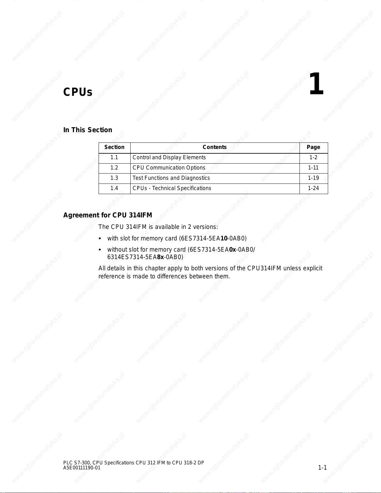
CPUs
In This Section
Section Contents Page
1.1 Control and Display Elements 1-2
1.2 CPU Communication Options 1-11
1.3 Test Functions and Diagnostics 1-19
1.4 CPUs - Technical Specifications 1-24
Agreement for CPU 314IFM
The CPU 314IFM is available in 2 versions:
with slot for memory card (6ES7314-5EA10-0AB0)
without slot for memory card (6ES7314-5EA0x-0AB0/
6314ES7314-5EA8x-0AB0)
All details in this chapter apply to both versions of the CPU314IFM unless explicit
reference is made to differences between them.
1
PLC S7-300, CPU Specifications CPU 312 IFM to CPU 318-2 DP
A5E00111190-01
1-1
Page 18
CPUs
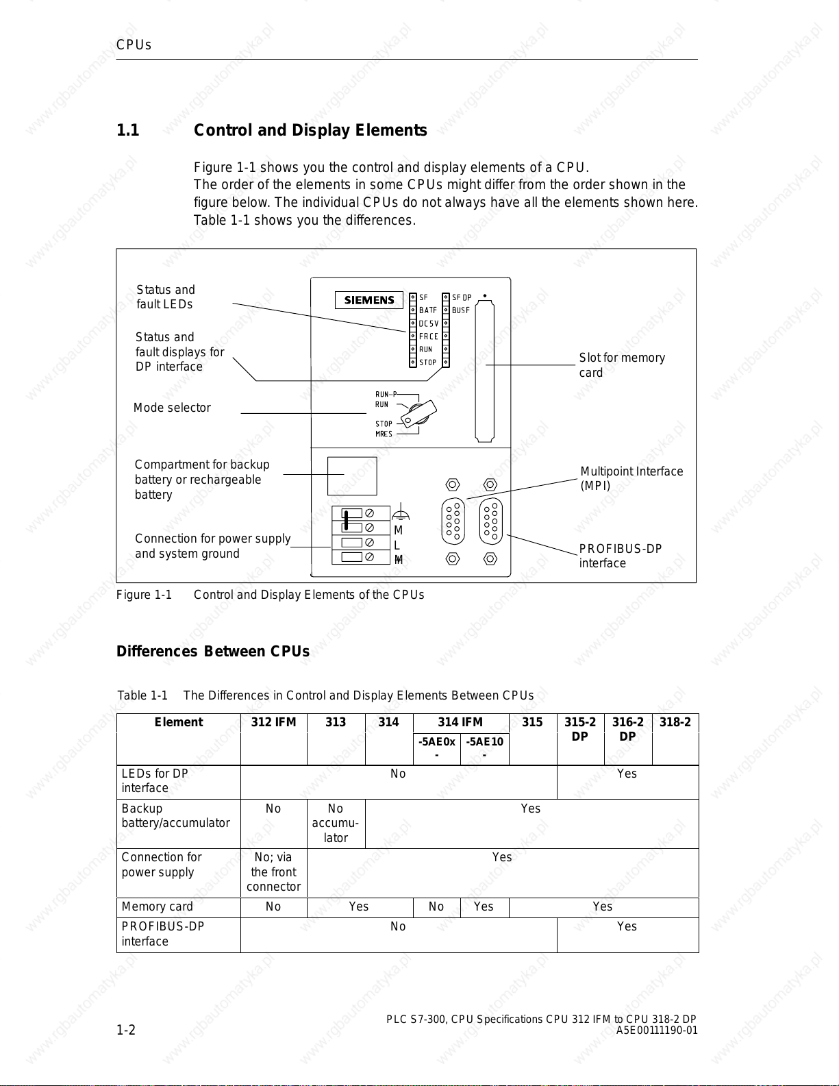
1.1 Control and Display Elements
Figure 1-1 shows you the control and display elements of a CPU.
The order of the elements in some CPUs might differ from the order shown in the
figure below. The individual CPUs do not always have all the elements shown here.
Table 1-1 shows you the differences.
Status and
fault LEDs
Status and
fault displays for
DP interface
Mode selector
Slot for memory
card
Compartment for backup
battery or rechargeable
battery
Connection for power supply
and system ground
Figure 1-1 Control and Display Elements of the CPUs
M
L
+M
Multipoint Interface
(MPI)
PROFIBUS-DP
interface
Differences Between CPUs
Table 1-1 The Differences in Control and Display Elements Between CPUs
Element 312 IFM 313 314
LEDs for DP
interface
Backup
battery/accumulator
Connection for
power supply
Memory card No Yes No Yes Yes
PROFIBUS-DP
interface
No No
accumu-
lator
No; via
the front
connector
No Yes
No Yes
314 IFM
-5AE0x--5AE10
315 315-2 316-2 318-2
DP DP
-
Yes
Yes
1-2
PLC S7-300, CPU Specifications CPU 312 IFM to CPU 318-2 DP
A5E00111190-01
Page 19
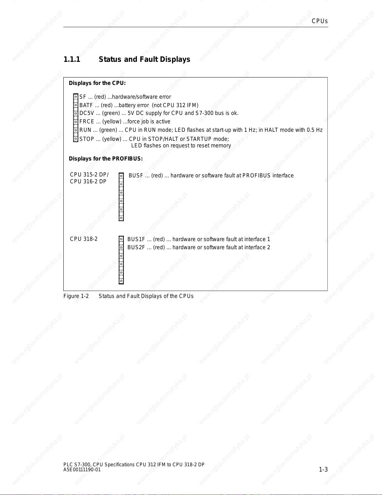
1.1.1 Status and Fault Displays
Displays for the CPU:
SF ... (red) ...hardware/software error
BATF ... (red) ...battery error (not CPU 312 IFM)
DC5V ... (green) ... 5V DC supply for CPU and S7-300 bus is ok.
FRCE ... (yellow) ...force job is active
RUN ... (green) ... CPU in RUN mode; LED flashes at start-up with 1 Hz; in HALT mode with 0.5 Hz
STOP ... (yellow) ... CPU in STOP/HALT or STARTUP mode;
LED flashes on request to reset memory
Displays for the PROFIBUS:
CPUs
CPU 315-2 DP/
CPU 316-2 DP
CPU 318-2
Figure 1-2 Status and Fault Displays of the CPUs
BUSF ... (red) ... hardware or software fault at PROFIBUS interface
BUS1F ... (red) ... hardware or software fault at interface 1
BUS2F ... (red) ... hardware or software fault at interface 2
PLC S7-300, CPU Specifications CPU 312 IFM to CPU 318-2 DP
A5E00111190-01
1-3
Page 20
CPUs
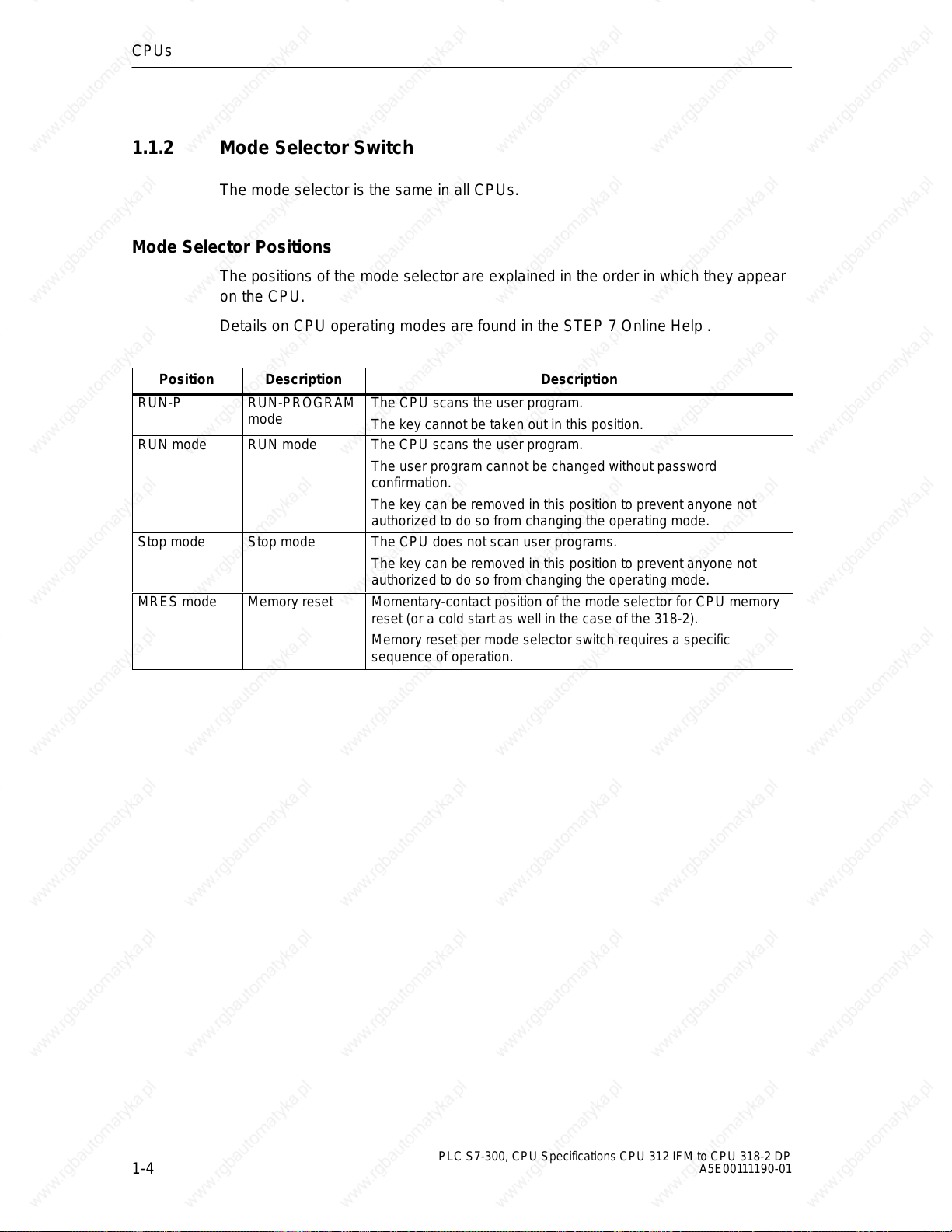
1.1.2 Mode Selector Switch
The mode selector is the same in all CPUs.
Mode Selector Positions
The positions of the mode selector are explained in the order in which they appear
on the CPU.
Details on CPU operating modes are found in the STEP 7 Online Help .
Position Description Description
RUN-P RUN-PROGRAM
mode
RUN mode RUN mode The CPU scans the user program.
Stop mode Stop mode The CPU does not scan user programs.
MRES mode Memory reset Momentary-contact position of the mode selector for CPU memory
The CPU scans the user program.
The key cannot be taken out in this position.
The user program cannot be changed without password
confirmation.
The key can be removed in this position to prevent anyone not
authorized to do so from changing the operating mode.
The key can be removed in this position to prevent anyone not
authorized to do so from changing the operating mode.
reset (or a cold start as well in the case of the 318-2).
Memory reset per mode selector switch requires a specific
sequence of operation.
1-4
PLC S7-300, CPU Specifications CPU 312 IFM to CPU 318-2 DP
A5E00111190-01
Page 21
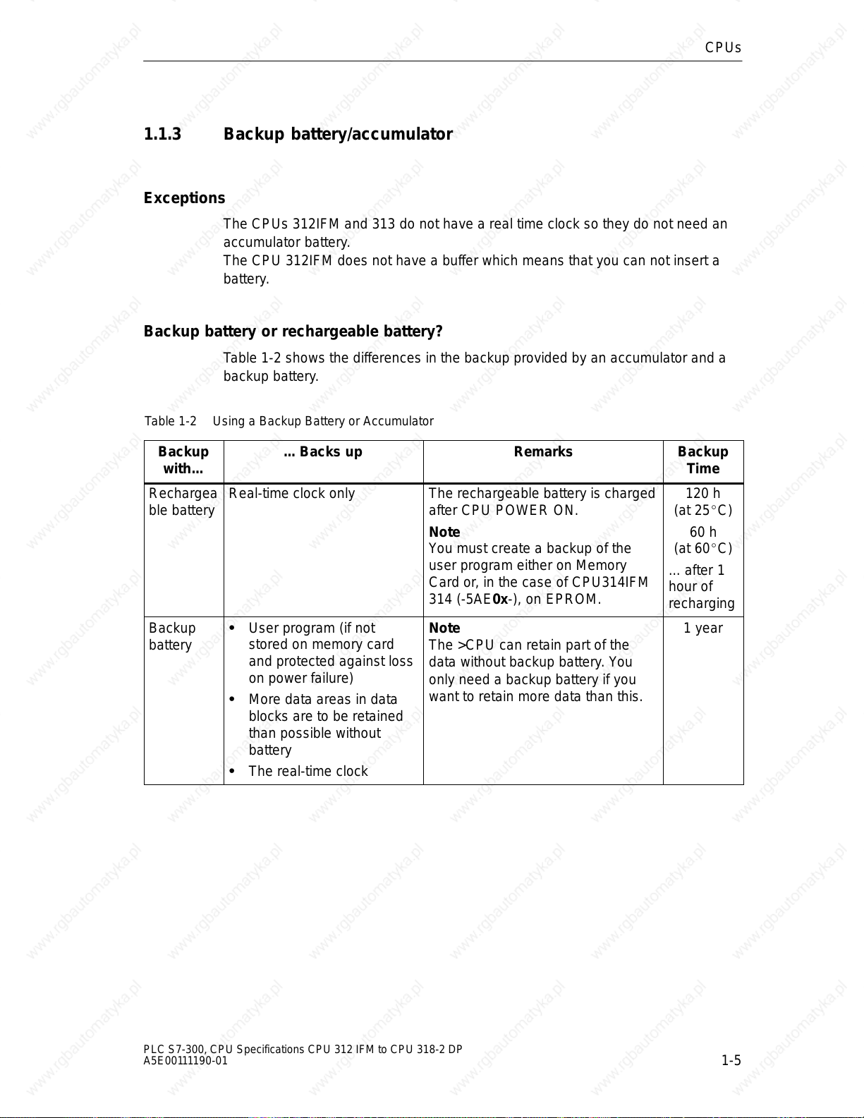
1.1.3 Backup battery/accumulator
Exceptions
The CPUs 312IFM and 313 do not have a real time clock so they do not need an
accumulator battery.
The CPU 312IFM does not have a buffer which means that you can not insert a
battery.
Backup battery or rechargeable battery?
Table 1-2 shows the differences in the backup provided by an accumulator and a
backup battery.
Table 1-2 Using a Backup Battery or Accumulator
CPUs
Backup
with...
Rechargea
ble battery
Backup
battery
... Backs up Remarks Backup
Real-time clock only The rechargeable battery is charged
after CPU POWER ON.
Note
You must create a backup of the
user program either on Memory
Card or, in the case of CPU314IFM
314 (-5AE0x-), on EPROM.
User program (if not
stored on memory card
and protected against loss
on power failure)
More data areas in data
blocks are to be retained
than possible without
battery
Note
The >CPU can retain part of the
data without backup battery. You
only need a backup battery if you
want to retain more data than this.
The real-time clock
Time
120 h
(at 25C)
60 h
(at 60C)
... after 1
hour of
recharging
1 year
PLC S7-300, CPU Specifications CPU 312 IFM to CPU 318-2 DP
A5E00111190-01
1-5
Page 22
CPUs
then uploaded from the memory card to
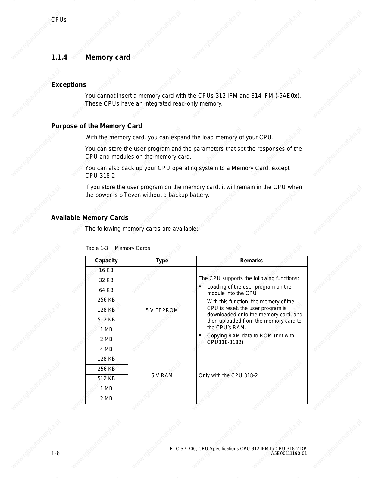
1.1.4 Memory card
Exceptions
You cannot insert a memory card with the CPUs 312 IFM and 314 IFM (-5AE0x).
These CPUs have an integrated read-only memory.
Purpose of the Memory Card
With the memory card, you can expand the load memory of your CPU.
You can store the user program and the parameters that set the responses of the
CPU and modules on the memory card.
You can also back up your CPU operating system to a Memory Card. except
CPU 318-2.
If you store the user program on the memory card, it will remain in the CPU when
the power is off even without a backup battery.
Available Memory Cards
The following memory cards are available:
Table 1-3 Memory Cards
Capacity
16 KB
32 KB
64 KB
256 KB
128 KB
512 KB
1 MB
2 MB
4 MB
128 KB
256 KB
512 KB
1 MB
2 MB
Type Remarks
The CPU supports the following functions:
Loading of the user program on the
module into the CPU
module into the CPU
With this function, the memory of the
With this function, the memory of the
5 V FEPROM
CPU is reset, the user program is
downloaded onto the memory card, and
then uploaded from the memory card to
the CPU’s RAM.
Copying RAM data to ROM (not with
CPU318-3182)
CPU318-3182)
5 V RAM Only with the CPU 318-2
1-6
PLC S7-300, CPU Specifications CPU 312 IFM to CPU 318-2 DP
A5E00111190-01
Page 23
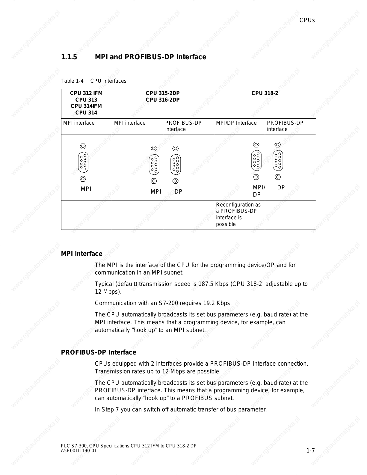
1.1.5 MPI and PROFIBUS-DP Interface
Table 1-4 CPU Interfaces
CPUs
CPU 312 IFM
CPU 313
CPU 314IFM
CPU 314
MPI interface MPI interface PROFIBUS-DP
MPI
- - - Reconfiguration as
CPU 315-2DP
CPU 316-2DP
MPI/DP Interface PROFIBUS-DP
interface
MPI DP
a PROFIBUS-DP
interface is
possible
CPU 318-2
MPI interface
The MPI is the interface of the CPU for the programming device/OP and for
communication in an MPI subnet.
MPI/
DP
interface
DP
-
Typical (default) transmission speed is 187.5 Kbps (CPU 318-2: adjustable up to
12 Mbps).
Communication with an S7-200 requires 19.2 Kbps.
The CPU automatically broadcasts its set bus parameters (e.g. baud rate) at the
MPI interface. This means that a programming device, for example, can
automatically ”hook up” to an MPI subnet.
PROFIBUS-DP Interface
CPUs equipped with 2 interfaces provide a PROFIBUS-DP interface connection.
Transmission rates up to 12 Mbps are possible.
The CPU automatically broadcasts its set bus parameters (e.g. baud rate) at the
PROFIBUS-DP interface. This means that a programming device, for example,
can automatically ”hook up” to a PROFIBUS subnet.
In Step 7 you can switch off automatic transfer of bus parameter.
PLC S7-300, CPU Specifications CPU 312 IFM to CPU 318-2 DP
A5E00111190-01
1-7
Page 24
CPUs
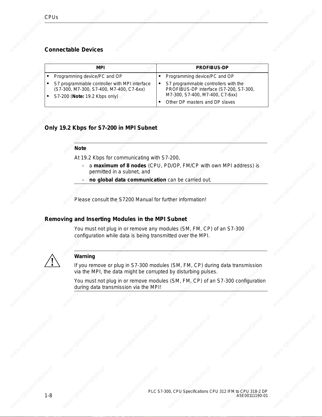
Connectable Devices
MPI PROFIBUS-DP
Programming device/PC and OP
S7 programmable controller with MPI interface
(S7-300, M7-300, S7-400, M7-400, C7-6xx)
S7-200 (Note: 19.2 Kbps only)
Only 19.2 Kbps for S7-200 in MPI Subnet
Note
At 19.2 Kbps for communicating with S7-200,
– a maximum of 8 nodes (CPU, PD/OP, FM/CP with own MPI address) is
permitted in a subnet, and
– no global data communication can be carried out.
Programming device/PC and OP
S7 programmable controllers with the
PROFIBUS-DP interface (S7-200, S7-300,
M7-300, S7-400, M7-400, C7-6xx)
Other DP masters and DP slaves
Please consult the S7200 Manual for further information!
Removing and Inserting Modules in the MPI Subnet
You must not plug in or remove any modules (SM, FM, CP) of an S7-300
configuration while data is being transmitted over the MPI.
Warning
!
If you remove or plug in S7-300 modules (SM, FM, CP) during data transmission
via the MPI, the data might be corrupted by disturbing pulses.
You must not plug in or remove modules (SM, FM, CP) of an S7-300 configuration
during data transmission via the MPI!
1-8
PLC S7-300, CPU Specifications CPU 312 IFM to CPU 318-2 DP
A5E00111190-01
Page 25

Loss of GD packets Following Change in the MPI Subnet During Operation
Warning
!
Loss of data packets in the MPI subnet:
Connecting an additional CPU to the MPI subnet during operation can lead to loss
of GD packets and to an increase in cycle time.
Remedy:
1. Disconnect the node to be connected from the supply.
2. Connect the node to the MPI subnet.
3. Switch the node on.
CPUs
PLC S7-300, CPU Specifications CPU 312 IFM to CPU 318-2 DP
A5E00111190-01
1-9
Page 26
CPUs
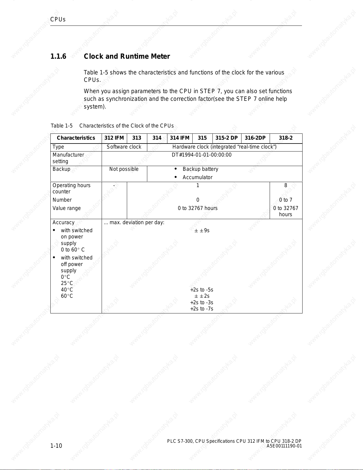
1.1.6 Clock and Runtime Meter
Table 1-5 shows the characteristics and functions of the clock for the various
CPUs.
When you assign parameters to the CPU in STEP 7, you can also set functions
such as synchronization and the correction factor(see the STEP 7 online help
system).
Table 1-5 Characteristics of the Clock of the CPUs
Characteristics
Type Software clock Hardware clock (integrated “real-time clock”)
Manufacturer
setting
Backup Not possible Backup battery
312 IFM 313 314 314 IFM 315 315-2 DP 316-2DP 318-2
DT#1994-01-01-00:00:00
Accumulator
Operating hours
counter
Number
Value range
Accuracy
with switched
on power
supply
0 to 60 C
with switched
off power
supply
0C
25C
40C
60C
- 1
0
0 to 32767 hours
... max. deviation per day:
9s
+2s to -5s
2s
+2s to -3s
+2s to -7s
8
0 to 7
0 to 32767
hours
1-10
PLC S7-300, CPU Specifications CPU 312 IFM to CPU 318-2 DP
A5E00111190-01
Page 27
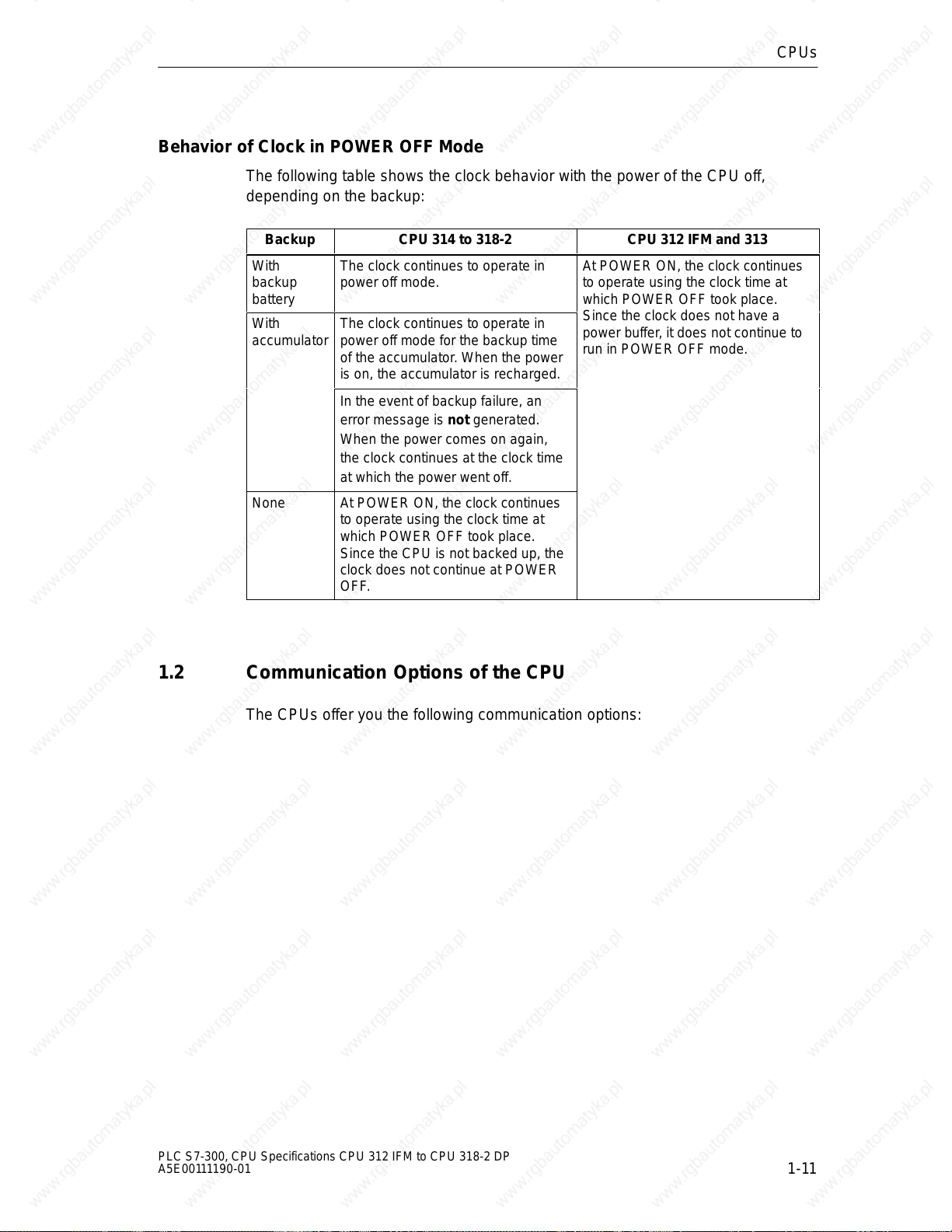
Behavior of Clock in POWER OFF Mode
The following table shows the clock behavior with the power of the CPU off,
depending on the backup:
Backup CPU 314 to 318-2 CPU 312 IFM and 313
With
backup
battery
With
accumulator
None At POWER ON, the clock continues
The clock continues to operate in
power off mode.
The clock continues to operate in
power off mode for the backup time
of the accumulator. When the power
is on, the accumulator is recharged.
In the event of backup failure, an
error message is not generated.
When the power comes on again,
the clock continues at the clock time
at which the power went off.
to operate using the clock time at
which POWER OFF took place.
Since the CPU is not backed up, the
clock does not continue at POWER
OFF.
CPUs
At POWER ON, the clock continues
to operate using the clock time at
which POWER OFF took place.
Since the clock does not have a
power buffer, it does not continue to
run in POWER OFF mode.
1.2 Communication Options of the CPU
The CPUs offer you the following communication options:
PLC S7-300, CPU Specifications CPU 312 IFM to CPU 318-2 DP
A5E00111190-01
1-11
Page 28
CPUs
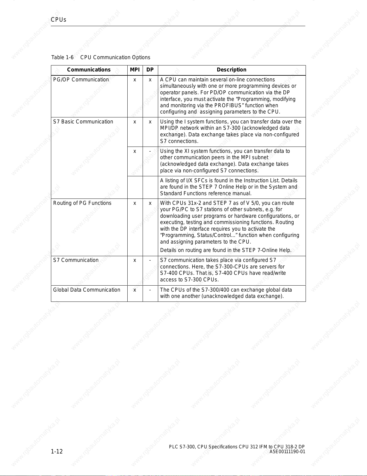
Table 1-6 CPU Communication Options
Communications
PG/OP Communication x x A CPU can maintain several on-line connections
S7 Basic Communication x x Using the I system functions, you can transfer data over the
Routing of PG Functions x x With CPUs 31x-2 and STEP 7 as of V 5/0, you can route
S7 Communication x - S7 communication takes place via configured S7
Global Data Communication x - The CPUs of the S7-300/400 can exchange global data
MPI DP Description
simultaneously with one or more programming devices or
operator panels. For PD/OP communication via the DP
interface, you must activate the “Programming, modifying
and monitoring via the PROFIBUS” function when
configuring and assigning parameters to the CPU.
MPI/DP network within an S7-300 (acknowledged data
exchange). Data exchange takes place via non-configured
S7 connections.
x - Using the XI system functions, you can transfer data to
other communication peers in the MPI subnet
(acknowledged data exchange). Data exchange takes
place via non-configured S7 connections.
A listing of I/X SFCs is found in the Instruction List. Details
are found in the STEP 7 Online Help or in the System and
Standard Functions reference manual.
your PG/PC to S7 stations of other subnets, e.g. for
downloading user programs or hardware configurations, or
executing, testing and commissioning functions. Routing
with the DP interface requires you to activate the
“Programming, Status/Control...” function when configuring
and assigning parameters to the CPU.
Details on routing are found in the STEP 7-Online Help.
connections. Here, the S7-300-CPUs are servers for
S7-400 CPUs. That is, S7-400 CPUs have read/write
access to S7-300 CPUs.
with one another (unacknowledged data exchange).
1-12
PLC S7-300, CPU Specifications CPU 312 IFM to CPU 318-2 DP
A5E00111190-01
Page 29
Connection Resources
Every communication connection requires a communication resource on the
S7 CPU as a management unit for the duration of the communication. Every
S7 CPU has a certain number of connection resources available to it according to
its technical specifications which can be assigned to various communication
services (PD/OP communication, S7 communication or S7 basic communication).
The distribution of connection resources differs between CPUs 312 IFM to 316-2
DP (see the table 3-6) and the CPU 318-2 (see Table 1-8):
CPUs
PLC S7-300, CPU Specifications CPU 312 IFM to CPU 318-2 DP
A5E00111190-01
1-13
Page 30
CPUs
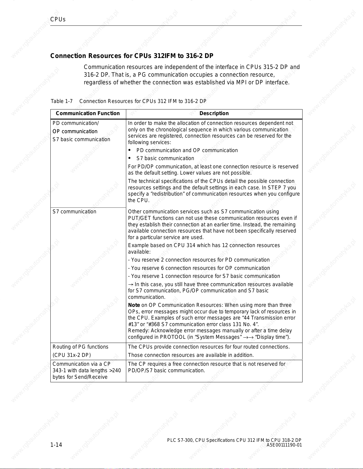
Connection Resources for CPUs 312IFM to 316-2 DP
Communication resources are independent of the interface in CPUs 315-2 DP and
316-2 DP. That is, a PG communication occupies a connection resource,
regardless of whether the connection was established via MPI or DP interface.
Table 1-7 Connection Resources for CPUs 312 IFM to 316-2 DP
Communication Function
PD communication/
OP communication
OP communication
S7 basic communication
In order to make the allocation of connection resources dependent not
only on the chronological sequence in which various communication
services are registered, connection resources can be reserved for the
following services:
Description
PD communication and OP communication
S7 basic communication
For PD/OP communication, at least one connection resource is reserved
as the default setting. Lower values are not possible.
The technical specifications of the CPUs detail the possible connection
resources settings and the default settings in each case. In STEP 7 you
specify a ”redistribution” of communication resources when you configure
the CPU.
S7 communication Other communication services such as S7 communication using
PUT/GET functions can not use these communication resources even if
they establish their connection at an earlier time. Instead, the remaining
available connection resources that have not been specifically reserved
for a particular service are used.
Example based on CPU 314 which has 12 connection resources
available:
- You reserve 2 connection resources for PD communication
- You reserve 6 connection resources for OP communication
- You reserve 1 connection resource for S7 basic communication
In this case, you still have three communication resources available
for S7 communication, PG/OP communication and S7 basic
communication.
Note on OP Communication Resources: When using more than three
OPs, error messages might occur due to temporary lack of resources in
the CPU. Examples of such error messages are “44 Transmission error
#13” or “#368 S7 communication error class 131 No. 4”.
Remedy: Acknowledge error messages manually or after a time delay
configured in PROTOOL (in “System Messages” →→ “Display time”).
Routing of PG functions The CPUs provide connection resources for four routed connections.
(CPU 31x-2 DP) Those connection resources are available in addition.
Communication via a CP
343-1 with data lengths >240
bytes for Send/Receive
The CP requires a free connection resource that is not reserved for
PD/OP/S7 basic communication.
1-14
PLC S7-300, CPU Specifications CPU 312 IFM to CPU 318-2 DP
A5E00111190-01
Page 31

Connection Resources for CPU 318-2
Table 1-8 Communication Resources for CPU 318-2
CPUs
Communication Function
PD/OP communication The CPU 318-2 provides a total of 32 connection resources (with CPU
as connection terminal point) for these communication functions. Those
32 connection resources can be freely allocated to the various
communication functions.
S7 basic communication
When allocating connection resources, you should observe the following
points:
Description
The number of connection resources differs for each interface as
follows:
– MPI/DP Interface 32 communication resources
Routing of PD functions
– DP-SS: 16 communication resources
In the case of connections that do not have the CPU as their terminal
point (e.g. an FM or in the case of routing) you must deduct 2
connection resources from the total resources and 1 connection
S7 communication
resource per interface.
Figure 1-3 shows the principle of allocation of connection resources.
An example of how connection resources are dimensioned is found in
Chapter LEERER MERKER.
Principle of Connection Resource Allocation for CPU 318-2
CPU 318-2
32 connection resources for
connections via the MPI/DP
interface
Figure 1-3 Principle of Connection Resource Allocation for CPU 318-2
PLC S7-300, CPU Specifications CPU 312 IFM to CPU 318-2 DP
A5E00111190-01
A total of 32 connection
resources for connections via
the MPI/DP and/or DP
interface
MPI/DP
DP
16 connection resources for
connections via the DP
interface
1-15
Page 32

CPUs
Interface Resources for CPU 318-2 - Example Calculation
1. Two network transitions by routing on the CPU
Resources used:
- 2 connection resources of the MPI/DP interface are used;
- 2 connection resources of the DP interface are used;
- all 4 connection resources available to both interfaces
are used;
2. 4 connections for S7 basic communication and PG/OP communication with the
CPU as connection terminal point via MPI/DP interface
Resources used:
- 4 connection resources of the MPI/DP interface are used;
- all 4 connection resources available to both interfaces
are used;
Resources still availabe:
- 26 connection resources of the MPI/DP interface;
- 14 connection resources of the DP interface;
- 24 of the connection resources available to both interfaces
Data Consistency for Communication
An essential aspect of the transmission of data between devices is its consistency.
The data that is transmitted together should all originate from the same processing
cycle and should thus belong together, i.e. be consistent.
If there is a programmed communication function such as X-SEND/ X-RCV which
accesses shared data, then access to that data area can be co-ordinated by
means of the parameter “BUSY” itself.
However, with S7 communication functions not requiring a block in the user
program of the 31x CPU (as server), e.g. PUT/GET or read/write operations via
OP communication, the dimension of data consistency must be taken into account
during programming. The following differences between CPUs 312IFM to 316-2 DP
and CPU 318-2 must be taken into account:
1-16
PLC S7-300, CPU Specifications CPU 312 IFM to CPU 318-2 DP
A5E00111190-01
Page 33
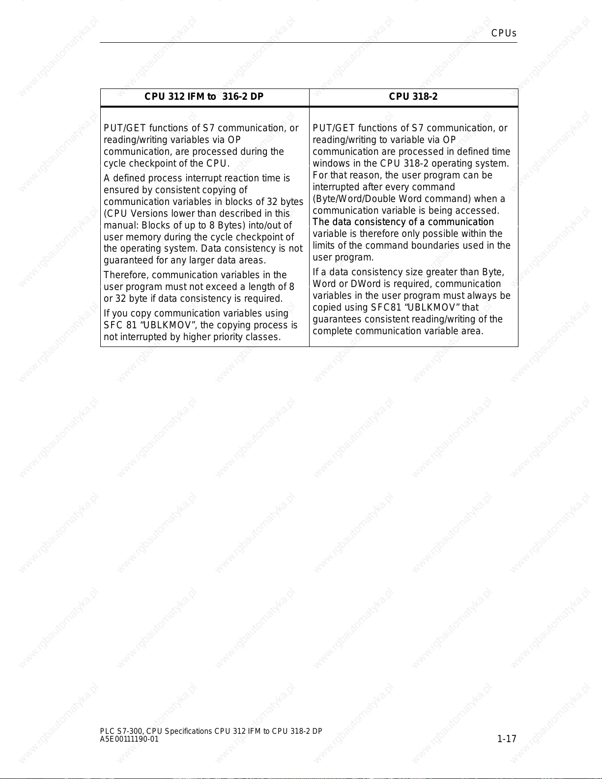
CPU 312 IFM to 316-2 DP CPU 318-2
CPUs
PUT/GET functions of S7 communication, or
reading/writing variables via OP
communication, are processed during the
cycle checkpoint of the CPU.
A defined process interrupt reaction time is
ensured by consistent copying of
communication variables in blocks of 32 bytes
(CPU Versions lower than described in this
manual: Blocks of up to 8 Bytes) into/out of
user memory during the cycle checkpoint of
the operating system. Data consistency is not
guaranteed for any larger data areas.
Therefore, communication variables in the
user program must not exceed a length of 8
or 32 byte if data consistency is required.
If you copy communication variables using
SFC 81 “UBLKMOV”, the copying process is
not interrupted by higher priority classes.
PUT/GET functions of S7 communication, or
reading/writing to variable via OP
communication are processed in defined time
windows in the CPU 318-2 operating system.
For that reason, the user program can be
interrupted after every command
(Byte/Word/Double Word command) when a
communication variable is being accessed.
The data consistency of a communication
The data consistency of a communication
variable is therefore only possible within the
limits of the command boundaries used in the
user program.
If a data consistency size greater than Byte,
Word or DWord is required, communication
variables in the user program must always be
copied using SFC81 “UBLKMOV” that
guarantees consistent reading/writing of the
complete communication variable area.
PLC S7-300, CPU Specifications CPU 312 IFM to CPU 318-2 DP
A5E00111190-01
1-17
Page 34

CPUs
Details
... on the communication topic are found in the STEP 7 Online Help and in the
manual Communication with SIMATIC.
... on communications SFCs/SFBs are found in the STEP 7 Online Help and in the
Standard and System functions reference manual.
Global Data Communication with S7-300 CPUs
Below you will find important features of global data communication in the S7-300.
Send/Receive Conditions
For the communication via GD circuits, you should observe the following
conditions:
Required for the GD packet transmitter is:
Reduction
ratio Transmitter
Required for the GD packet receiver is:
Reduction
time Transmitter
ratio Receiver
Non-observance of these conditions can lead to the loss of a GD packet. The
reasons for this are:
Cycle
Cycle
time Transmitter
timer eceiver
60 ms (CPU 318-2: 10 ms
Reduction
ratio Transmitter
Cycle
The performance capability of the smallest CPU in the GD circuit
Sending and receiving of global data is carried out asynchronously by the
sender and receiver.
Loss of global data is displayed in the status field of a GD circuit if you have
configured this with STEP 7.
Note
Note when communicating via global data: sent global data is not acknowledged
by the receiving partner!
The sender therefore receives no information on whether a receiver and which
receiver has received the sent global data.
Send Cycles for Global Data
In STEP 7 (as of Version 3.0), the following situation can arise if you set “Send
after every CPU cycle” with a short CPU cycle time (< 60 ms): the operating
system overwrites GD packets the CPU has not yet transmitted. Tip: Loss of
global data is displayed in the status field of a GD circuit if you have configured this
with STEP 7.
1-18
PLC S7-300, CPU Specifications CPU 312 IFM to CPU 318-2 DP
A5E00111190-01
Page 35

1.3 Test Functions and Diagnostics
The CPUs provide you with:
Testing functions for commissioning
Diagnostics via LEDs and STEP 7.
1.3.1 Testing Functions
The CPUs offer you the following testing functions:
Monitor Variables
Modify Variables
Forcing (note the differences between CPUs)
Monitor block
CPUs
Set Breakpoint
Details on the testing functions are found in the STEP 7 Online Help.
Important for the Status FB!
The STEP 7 function “Status FB” increases CPU cycle time!
In STEP 7 you can specify a maximum permissible increase in cycle time (not
CPU 318-2). In this case, in STEP 7 you must specify process mode for the CPU
parameters.
PLC S7-300, CPU Specifications CPU 312 IFM to CPU 318-2 DP
A5E00111190-01
1-19
Page 36

CPUs
Different Features of Forcing S7-300
Please note the different features of forcing in the different CPUs:
CPU 318-2 CPU 312IFM to 316-2DP
The variables of a user program with
fixed preset values (force values)
cannot be changed or overwritten by
the user program.
It is not permissible to force peripheral
or process image areas lying in the
range of consistent user data.
The following can be variables:
Inputs/outputs
Peripheral I/Os
Memory markers
You can force up to 256 variables.
The variables of a user program with
fixed preset values (force values) can
be changed or overwritten in the user
program.
(See Figure 1-4 on page 1-21)
The following can be variables:
Inputs/Outputs
You can force up to 10 variables.
1-20
PLC S7-300, CPU Specifications CPU 312 IFM to CPU 318-2 DP
A5E00111190-01
Page 37

Forcing with the CPU 312 IFM to 316-2 DP:
Caution
!
With S7-300 CPUs, forcing is the same as “cyclical modify”
Forced values in the input process image can be overwritten by write instructions
(e.g. T EB x, = E x.y, copying with SFC etc.) and peripheral read instructions (e.g.
L PEW x) in the user program, as well as by write instructions of PG/OP opera-
tions!
Outputs initialized with forced values only return the forced value if the user pro-
gram does not execute any write accesses to the outputs using peripheral write
commands (e.g. TPQB x ) and if no PG/OP functions write to these outputs!
Always note that forced values in the I/O process image cannot be overwritten by
the user program or PG/OP functions!
Execute force
job for inputs
CPUs
Execute force
job for inputs
PIO
transfer
Execute force
job for outputs
OS .... Operating system execution
Figure 1-4 The Principle of Forcing with S7-300 CPUs (CPU 312IFM to 316-2DP)
OS
PII
transfer
Forced
value
User program
Forced value
overwritten by T
PQW!
T PQW
PIO
transfer
Execute force
job for outputs
OS
Forced
value
PII
transfer
PLC S7-300, CPU Specifications CPU 312 IFM to CPU 318-2 DP
A5E00111190-01
1-21
Page 38

CPUs
1.3.2 Diagnostics with LED Display
In Table 1-9, only the LEDs relevant to the diagnosis of the CPU and S7-300 are
listed. You will find the significance of the PROFIBUS-DP interface LEDs explained
in Chapter 2.
Table 1-9 Diagnostic LEDs of the CPU
LED
SF Comes on in
the event of
BATF Comes on
when
Stop Comes on
when
Flashes when
Hardware faults
Programming errors
Parameter assignment errors
Calculation errors
Timing errors
Faulty memory card
Battery fault or no backup at power on
I/O fault/error (external I/O only)
Communication error
The backup battery is missing, faulty or not charged.
Note Also lit if a rechargeable battery is installed. Reason:
The user program is not backed up the rechargeable battery.
The CPU is not processing a user program
The CPU requests a memory reset
1.3.3 Diagnostics with STEP 7
Description
1-22
Note
Please note that this is not a fail-safe or redundant system, regardless of its exi-
sting extensive monitoring and error reaction functions.
If an error occurs, the CPU enters the cause of the error in the diagnostic buffer.
You can read the diagnostic buffer using the programming device.
The CPU switches to STOP if an error or interrupt event occurs, or your user
program reacts accordingly with error or interrupt OBs. Details on STEP 7
diagnostic functions are found in the STEP 7 Online Help.
In the Instruction list you can find an overview
of the OBs you can use to react to respective error or interrupt events, as well
as of the OBs you can program in the respective CPU
PLC S7-300, CPU Specifications CPU 312 IFM to CPU 318-2 DP
A5E00111190-01
Page 39

CPU Reaction on Missing Error OB
If you have not programmed an error OB, the CPU reacts as follows:
CPU goes into STOP on missing ... CPU Remains in RUN with Missing ...
OB 80 (Runtime error)
OB 85 (Program cycle error)
OB 86 (Station failure in the PROFIBUS-
DP subnet)
OB 87 (Communication error)
OB 121 (Programming error)
OB 122 (Peripheral direct access
error)
CPU Behavior When There Is No Interrupt OB
If you have not programmed an interrupt OB, the CPU reacts as follows:
CPUs
OB 81 (Power break)
CPU goes into STOP on missing ... CPU Remains in RUN with Missing ...
OB 10/11 (TOD interrupt)
OB 20/21 (Delay interrupt)
OB 40/41 (Process interrupt)
OB 55 (TOD interrupt)
OB 56 (Delay interrupt)
OB 57 (for manufacturer-specific
interrupts)
OB 82 (Diagnostic interrupt)
OB 83 (Insertion/Removal interrupt)
Tip on OB35 (CPU 318-2: also OB32)
For the watchdog interrupt OB 35/32, you can specify times starting from 1 ms.
Note: The smaller the selected watchdog interrupt period, the more likely
watchdog interrupt errors will occur. You must take into account the operating
system times of the CPU in question, the runtime of the user program and the
extension of the cycle by active programming device functions, for example.
OB 32/35 (Watchdog interrupt)
PLC S7-300, CPU Specifications CPU 312 IFM to CPU 318-2 DP
A5E00111190-01
1-23
Page 40

CPUs
1.4 CPUs - Technical Specifications
In This Section
You will find the technical specifications of the CPU.
You will find the technical specifications of the integrated inputs/outputs of the
CPU 312 IFM and 314 IFM.
You will not find the features of the CPU 31x-2 DP as a DP master/DP slave.
Refer to Chapter 2.
Section Contents Page
1.4.1 CPU 312 IFM 1-25
1.4.2 CPU 313 1-37
1.4.3 CPU 314 1-40
1.4.4 CPU 314 IFM 1-43
1.4.5 CPU 315 1-60
1.4.6 CPU 315-2 DP 1-63
1.4.7 CPU 316-2 DP 1-66
1.4.8 CPU 318-2 1-69
1-24
PLC S7-300, CPU Specifications CPU 312 IFM to CPU 318-2 DP
A5E00111190-01
Page 41

1.4.1 CPU 312 IFM
Special Features
Integrated I/Os (Wiring via 20-pole front connector)
No backup battery and therefore maintenance-free
An S7-300 with CPU 312 IFM can be mounted only on one rack
Integrated Functions of the CPU 312 IFM
Integrated Functions Description
Process interrupt Interrupt input means: inputs configured with this function trigger a process
interrupt at the corresponding signal edge.
Interrupt input options for the digital inputs 124.6 to 125.1 must be programmed
in STEP 7.
Counter The CPU 312 IFM offers these special functions as an alternative at the digital
inputs 124.6 to 125.1.
Frequency meter
For a description of the special functions “Counter” and “Frequency meter”,
please refer to the Integrated Functions Manual.
CPUs
“Interrupt Inputs” of the CPU 312 IFM
If you wish to use the digital inputs 124.6 to 125.1 as interrupt inputs, you must
program these in STEP 7 in the CPU parameters.
Note the following points:
These digital inputs have a very low signal delay. At this interrupt input, the
module recognizes pulses with a length as of approx. 10 to 50 s. Always use
shielded cable to connect active interrupt inputs in order to avoid interrupts
triggered by line interference.
Note The minimum pulse width of an interrupt trigger pulse is 50 s.
The input status associated with an interrupt in the input process image or with
LPIB always changes with ”normal” input delay of approx.3 ms.
PLC S7-300, CPU Specifications CPU 312 IFM to CPU 318-2 DP
A5E00111190-01
1-25
Page 42

CPUs
Start information for OB40
Table 1-10 shows the temporary (TEMP) variables of OB40 relevant for the
“Interrupt inputs” of the CPU 312 IFM. Refer to theSystem and Standard functions
reference manual for details on the process interrupt OB.
Table 1-10 Start Information for OB 40 for the Interrupt Inputs of the Integrated I/Os
Byte
6/7 OB40_MDL_ADDR WORD B#16#7C Address of the interrupt triggering
8 on OB40_POINT_ADDR DWORD See Figure 1-5 Signaling of the interrupt triggering
Variable Data Type Description
module (in this case, the CPU)
integrated inputs
Display of the Interrupt Inputs
In variable OB40_POINT_ADDR, you can view the interrupt inputs which have
triggered a process interrupt. Figure 1-5 shows the allocation of the interrupt inputs
to the bits of the double word.
Note: Several bits can be set if interrupts are triggered by several inputs within
short intervals (< 100 s). That is, the OB is started once only, even if several
interrupts are pending.
31 30
54 13
Reserved
2
0 Bit No.
PRIN from I124.6
PRIN from I 124.7
PRIN from I125.0
PRIN from I 125.1
1-26
PRIN: Process interrupt
Figure 1-5 Display of the States of the Interrupt Inputs of the CPU 312 IFM
PLC S7-300, CPU Specifications CPU 312 IFM to CPU 318-2 DP
A5E00111190-01
Page 43

Front View
CPUs
Status and
fault LEDs
Mode selector
Multipoint Interface
(MPI)
Figure 1-6 Front View of the CPU 312 IFM
I124.0
I1
I2
I3
I4
I5
I6
I7
I125.0
I1
Q124.0
Q1
Q2
Q3
Q4
Q5
Front connector,
used to connect
the integrated
I/O, power
supply and
system ground.
PLC S7-300, CPU Specifications CPU 312 IFM to CPU 318-2 DP
A5E00111190-01
1-27
Page 44

CPUs
Technical Specifications of the CPU 312 IFM
CPU and Product Version
MLFB
Hardware version
6ES7 312-5AC02-0AB0
01
Firmware version V 1.1.0
Matching programming
package
Memory
Work memory
STEP 7 V 5.0;
Service Pack 03
integral 6 KB
Expandable no
Load memory
integral 20 KB RAM
20 KB EEPROM
Expandable FEPROM no
Expandable RAM no
Backup Yes
With battery no
Without battery 72 bytes retentive
Configurable
(data, flags, timers)
Processing times
Processing times for
Bit instructions 0.6 s minimum
W ord instructions 2 s minimum
Double integer math 3 s minimum
Floating-point math
instructions
Timers/Counters and their retentive characteristics
S7 counters 32
60 s minimum
Data areas and their retentive characteristics
Retentive data area as a
whole (inc. flags, timers,
counters)
Bit memories 1024
Adjustable retentivity MB 0 to MB 71
Preset MB 0 to MB 15
Clock memories 8 (1 memory byte)
Data blocks max. 63 (DB 0 reserved)
Size max. 6 KB
Adjustable retentivity max. 1 DB, 72 bytes
Preset No retentivity
Local data (non-alterable) max. 512 bytes
Per priority class 256 bytes
Blocks
OBs See Instruction List
Size max. 6 KB
Nesting depth
Per priority class 8
additional levels within
FBs max. 32;
Size max. 6 KB
FCs max. 32;
Size max. 6 KB
Address areas (I/O)
Peripheral address area
Digital
Adjustable retentivity from C 0 to C 31
Preset from C 0 to C 7
Counting range 1 to 999
IEC Counters Yes
Type SFBs
S7 timers 64
Adjustable retentivity No
Analog 256 to 383/256 to 383
Process image (cannot be
customized)
Digital channels 256+10 integrated/256+6
Analog channels 64/32
Timing range 10 ms to 9990 s
IEC Timers Yes
Type
SFBs
an error OB
– integrated
max. 1 DB, 72 data bytes
None
0 to 31/0 to 31
124,125 E/124 A
32 bytes+4 bytes
integrated/ 32 bytes+4
bytes integrated
integrated
1-28
PLC S7-300, CPU Specifications CPU 312 IFM to CPU 318-2 DP
A5E00111190-01
Page 45

CPUs
Configuration
Rack 1
Modules per module rack max. 8
DP Master
integral None
via CP Yes
S7 message functions
Simultaneously active
Alarm-S blocks
Time
Real-time clock Yes
None
Backed-up No
Accuracy See Section 1.1.6
Operating hours counter No
Clock synchronisation Yes
On PLC Master
On MPI Master/Slave
Testing and commissioning functions
Status/Modify Variables Yes
Variable Inputs, outputs, flags, DBs,
timers, counters
Number
– Monitor Variables
– Modify Variables
Force Yes
max. 30
max. 14
Variable Inputs, outputs
Number max. 10
Monitor block Yes
Single sequence
Breakpoint
Diagnostic buffer Yes
Number of entries
(non-alterable)
Yes
2
100
Communication functions
PD/OP communication Yes
Global data communication Yes
Number of GD packets
– Sender 1
– Receiver 1
Size of GD packets max. 22 bytes
– Number of which
consistent
S7 basic communication Yes
8 bytes
User data per job max. 76 bytes
– Number of which
consistent
S7 communication Yes (server)
32 bytes for X/I_PUT/_GET;
76 bytes for
X_SEND/_RCV
User data per job max. 160 bytes
– Number of which
consistent
S7-compatible
communication
Standard communication No
Number of connection
resources
32 bytes
No
6 for PD/OP/S7 basic/S7
communication
Reservation for
– PD communication
User-definable
Default
– OP communication
User-definable
Default
– S7 basic
communication
User-definable
Default
Interfaces
1. Interface
Functionality
max. 5
from 1 to 5
1
max. 5
from 1 to 5
1
max. 2
from 0 to 2
2
MPI Yes
DP Master No
DP Slave No
Galvanically isolated No
PLC S7-300, CPU Specifications CPU 312 IFM to CPU 318-2 DP
A5E00111190-01
1-29
Page 46

CPUs
MPI
Services
– PD/OP
communication
– Global data
communication
– S7 basic
communication
– S7 communication Yes (server)
Yes
Yes
Yes
T ransmission rates 19.2; 187.5 Kbps
Dimensions
Assembly dimension
BHT (mm)
Weight Approx. 0.45 kg
Programming
Programming language STEP 7
Stored instructions See Instruction List
Nesting levels 8
System functions (SFCs) See Instruction List
System function blocks
(SFBs)
User program security Password protection
80125130
See Instruction List
Voltages, Currents
Power supply 24V DC
Permissible range 20.4 to 28.8 V
Current consumption (idle) typical 0.7 A
Inrush current typical 8A
l 2 t 0.4 A2s
External fusing for supply
lines (recommendation)
PG supply on MPI (15 to
30V DC)
Power losses typical 9 W
Battery No
Accumulator No
Integrated inputs/outputs
Addresses of integral
Circuit breaker; 10 A,
Type B or C
max. 200 mA
Digital inputs E 124.0 to E 127.7
Digital outputs A 124.0 to A 124.7
Integrated Functions
Counter 1 (see Integrated
Frequency meter up to 10 kHz max.
Functions)
manual
(see Integrated Functions)
manual
1-30
PLC S7-300, CPU Specifications CPU 312 IFM to CPU 318-2 DP
A5E00111190-01
Page 47

Technical Specifications of the Special Inputs of the CPU 312IFM
CPUs
Module-Specific Data
Number of inputs 4
I 124.6 to 125.1
Cable length
Shielded max. 100 m (109yd.)
V oltages, Currents, Potentials
Number of inputs that can
be triggered simultaneously
4
(horizontal
configuration)
up to 60°C
(vertical configuration)
up to 40°C
Status, Interrupts; Diagnostics
Status display 1 green LED per
Interrupts
4
4
channel
Process interrupt Configurable
Diagnostic functions None
Sensor Selection Data
Input voltage
Rated value
For “1” signal
I 125.0 and I 125.1
I 124.6 and I 124.7
For “0” signal
Input current
For “1” signal
I 125.0 and I 125.1
I 124.6 and I 124.7
Input delay time
For “0” to “1”
For “1” to “0”
Input characteristic
E 125.0 and E 125.1
E 124.6 and 124.7
Connection of 2-wire
BEROs
Permissible idle current
I 125.0 and I 125.1
I 124.6 and I 124.7
Time, Frequency
24V DC
15 to 30 V
15 to 30 V
-3 to 5 V
min. 2 mA
min. 6.5 mA
max. 50 s
max. 50 s
to IEC 1131, Type 1
to IEC 1131, Type 1
no
max. 0.5 mA
max. 2 mA
Internal conditioning time
for
Interrupt processing
Input frequency 10 kHz
PLC S7-300, CPU Specifications CPU 312 IFM to CPU 318-2 DP
A5E00111190-01
max. 1.5 ms
1-31
Page 48

CPUs
Technical Specifications of the Digital Inputs of the CPU 312IFM
Note
Alternatively, you can configure the inputs I 124.6 and I 124.7 as special inputs, in
which case the technical specifications listed for the special inputs apply to the
inputs I 124.6 and I 124.7.
Module-Specific Data
Number of inputs 8
Cable length
Unshielded
Shielded
V oltages, Currents, Potentials
Number of inputs that can
be triggered simultaneously
max. 600 m
max. 1000 m
8
(horizontal
configuration)
up to 60°C
(vertical configuration)
up to 40°C
Galvanic isolation No
8
8
Status, Interrupts; Diagnostics
Status display 1 green LED per
channel
Interrupts None
Diagnostic functions None
Sensor Selection Data
Input voltage
Rated value
For “1” signal
For “0” signal
Input current
24V DC
11 to 30 V
-3 to 5 V
For “1” signal typical 7 mA
Input delay time
For “0” to “1”
For “1” to “0”
Input characteristic to IEC 1131, Type 2
Connection of 2-wire
BEROs
Permissible quiescent
current
1.2 to 4.8 ms
1.2 to 4.8 ms
Possible
max. 2 mA
1-32
PLC S7-300, CPU Specifications CPU 312 IFM to CPU 318-2 DP
A5E00111190-01
Page 49

Technical Specifications of the Digital Outputs of the CPU 312IFM
CPUs
Module-Specific Data
Number of outputs 6
Cable length
Unshielded
Shielded
V oltages, Currents, Potentials
Total current of outputs (per
group)
max. 600 m
max. 1000 m
(horizontal
configuration)
up to 40°C
up to 60°C
(vertical configuration)
up to 40°C
Galvanic isolation No
Status, Interrupts; Diagnostics
Status display 1 green LED per
Interrupts None
Diagnostic functions None
max. 3 A
max. 3 A
max. 3 A
channel
Actuator Selection Data
Output voltage
For “1” signal min. L+ (-0.8 V)
Output current
For “1” signal
Rated value
Permissible range
0.5 A
5 mA to 0.6 A
For “0” signal
Residual current
Load impedance range 48 to 4 k
Lamp load max. 5 W
Parallel connection of 2
outputs
For dual-channel
triggering of a load
For performance
increase
Triggering of a digital input Possible
Switching frequency
For resistive load
For inductive load to
IEC947-5-1, DC 13
For lamp load
Inductive breaking voltage
limited internally to
max. 0.5 mA
Possible
Not possible
max. 100 Hz
max. 0.5 Hz
max. 100 Hz
typical V 30
Short-circuit protection of
the output
Response threshold
PLC S7-300, CPU Specifications CPU 312 IFM to CPU 318-2 DP
A5E00111190-01
yes, electronically
timed
typical 1 A
1-33
Page 50

CPUs
Wiring diagram of the CPU 312 IFM
Figure 1-7 shows the wiring diagram of the CPU 312 IFM. Use a 20-pole front
connector to wire the CPU’s integrated I/O.
Caution
!
The CPU 312 IFM has no reverse polarity protection. Polarity reversal destroys
the integrated outputs. Nonetheless, in this case the CPU does not switch to
STOP and the status displays are lit. In other words, the fault is not indicated.
I124.0
I1
I2
I3
I4
I5
I6
I7
I125.0
Figure 1-7 Wiring diagram of the CPU 312 IFM
Grounded Configuration Only
You can use the CPU 312 IFM in a grounded configuration only. In the CPU 312
IGFM, system ground is connected internally to chassis ground (M) (see
Figure 1-8, page 1-36).
I1
Q124.0
Q1
Q2
Q3
Q4
Q5
1-34
PLC S7-300, CPU Specifications CPU 312 IFM to CPU 318-2 DP
A5E00111190-01
Page 51

Power Supply Connections
The
CPU 312 IFM and
the integrated I/Os
are connected to power at the terminals 18 and 19 (see Figure 1-7).
Short-circuit reaction
On short-circuit at one of the integrated outputs of CPU 312 IFM, proceed as
follows:
1. Switch the CPU 312 IFM to STOP or switch off the power supply.
2. Eliminate the cause of the short-circuit.
3. Switch the CPU 312 IFM back to RUN or switch the power supply back on.
CPUs
PLC S7-300, CPU Specifications CPU 312 IFM to CPU 318-2 DP
A5E00111190-01
1-35
Page 52

CPUs
Basic Circuit Diagram of the CPU 312 IFM
Figure 1-8 shows the block diagram of CPU 312 IFM.
CPU
CPU power
supply
Figure 1-8 Basic Circuit Diagram of the CPU 312 IFM
L +
M
M
1-36
PLC S7-300, CPU Specifications CPU 312 IFM to CPU 318-2 DP
A5E00111190-01
Page 53

1.4.2 CPU 313
Technical Specifications of the CPU 313
CPU and Product Version
MLFB
Hardware version
Firmware version V 1.1.0
Matching programming
package
Memory
Work memory
integral 12 KB
Expandable no
Load memory
integral 20 KB RAM
Expandable FEPROM Up to 4 MB
Expandable RAM no
Backup Yes
With battery All data
Without battery 72 bytes retentive
Processing times
Processing times for
Bit instructions 0.6 s minimum
W ord instructions 2 s minimum
Double integer math 2 s minimum
Floating-point math
instructions
Timers/Counters and their retentive characteristics
S7 counters 64
Adjustable retentivity from C 0 to C 63
Preset from C 0 to C 7
Counting range 1 to 999
IEC Counters Yes
Type SFB
S7 timers 128
Adjustable retentivity from T 0 to T 31
Preset No retentive times
Timing range 10 ms to 9990 s
IEC Timers Yes
Type
6ES7 313-1AD03-0AB0
01
STEP 7 V 5.0;
Service Pack 03
Configurable
(data, flags, timers)
60 s minimum
SFB
CPUs
Data areas and their retentive characteristics
Retentive data area as a
whole (inc. flags, timers,
counters)
Bit memories 2048
max. 1 DB, 72 data bytes
Adjustable retentivity MB 0 to MB 71
Preset MB 0 to MB 15
Clock memories 8 (1 memory byte)
Data blocks max. 127 (DB 0 reserved)
Size max. 8 KB
Adjustable retentivity 1 DB, 72 bytes
Preset No retentivity
Local data (non-alterable) max. 1536 bytes
Per priority class 256 bytes
Blocks
OBs See Instruction List
Size max. 8 KB
Nesting depth
Per priority class 8
additional levels within
an error OB
FBs 128
4
Size max. 8 KB
FCs 128
Size max. 8 KB
Address areas (I/O)
Peripheral address area
Digital 0 to 31/0 to 31
Analog 256 to 383/256 to 383
Process image (cannot be
customized)
Digital channels max. 256/256
Analog channels max. 64/32
32 bytes/32 bytes
PLC S7-300, CPU Specifications CPU 312 IFM to CPU 318-2 DP
A5E00111190-01
1-37
Page 54

CPUs
Configuration
Rack 1
Modules per module rack max. 8
Number of DP masters
integral No
via CP 1
S7 message functions
Simultaneously active
Alarm-S blocks
Time
Real-time clock Yes
None
Backed-up No
Accuracy See Section 1.1.6
Operating hours counter 1
Number 0
Value range 0 to 32767 hours
Selectivity 1 hour
Retentive Yes
Clock synchronisation Yes
On PLC Master
On MPI Master/Slave
Testing and commissioning functions
Status/Modify Variables Yes
Variable Inputs, outputs, flags, DBs,
timers, counters
Number
– Monitor Variables
– Modify Variables
Force Yes
max. 30
max. 14
Variable Inputs, outputs
Number max. 10
Monitor block Yes
Single sequence
Breakpoint
Diagnostic buffer Yes
Number of entries
(non-alterable)
Yes
2
100
Communication functions
PD/OP communication Yes
Global data communication Yes
Number of GD packets
– Sender 1
– Receiver 1
Size of GD packets max. 22 bytes
– Number of which
consistent
S7 basic communication Yes
8 bytes
User data per job max. 76 bytes
– Number of which
consistent
S7 communication Yes (server)
32 bytes for X/I_PUT/_GET;
76 bytes for
X_SEND/_RCV
User data per job max. 160 bytes
– Number of which
consistent
S7-compatible
communication
Standard communication No
Number of connection
resources
32 bytes
No
8 for PD/OP/S7 basic/S7
communication
Reservation for
– PD communication
User-definable
Default
– OP communication
User-definable
Default
– S7 basic
communication
User-definable
Default
Interfaces
1. Interface
Functionality
max. 7
from 1 to 7
1
max. 7
from 1 to 7
1
max. 4
from 0 to 4
4
MPI Yes
DP Master No
DP Slave No
Galvanically isolated No
1-38
PLC S7-300, CPU Specifications CPU 312 IFM to CPU 318-2 DP
A5E00111190-01
Page 55

CPUs
MPI
Services
– PD/OP
communication
– Global data
communication
– S7 basic
communication
– S7 communication Yes (server)
Yes
Yes
Yes
T ransmission rates 19.2; 187.5 Kbps
Dimensions
Assembly dimension
BHT (mm)
Weight Approx. 0.53 kg
Programming
Programming language STEP 7
Stored instructions See Instruction List
Nesting levels 8
System functions (SFCs) See Instruction List
System function blocks
(SFBs)
User program security Password protection
80125130
See Instruction List
Voltages, Currents
Power supply 24V DC
Permissible range 20.4 to 28.8
Current consumption (idle) typical 0.7 A
Inrush current typical 8A
l 2 t 0.4 A2s
External fusing for supply
lines (recommendation)
PD supply at MPI (15 to
30V DC)
Power losses typical 8 W
Battery
Backup margin at 25
C and continuous CPU
buffering
Battery shelf life at
25C
Accumulator No
Circuit breaker; 2 A
Type B or C
max. 200 mA
min. 1 year
approx. 5 years
PLC S7-300, CPU Specifications CPU 312 IFM to CPU 318-2 DP
A5E00111190-01
1-39
Page 56

CPUs
1.4.3 CPU 314
Technical Specifications of the CPU 314
CPU and Product Version
MLFB
Hardware version
Firmware version V 1.1.0
Matching programming
package
Memory
Work memory
integral 24 KB
Expandable no
Load memory
integral 40 KB RAM
Expandable FEPROM Up to 4 MB
Expandable RAM no
Backup Yes
With battery All data
Without battery 4736 bytes, configurable,
Processing times
Processing times for
Bit instructions 0.3 s minimum
W ord instructions 1 s minimum
Double integer math 2 s minimum
Floating-point math
instructions
Timers/Counters and their retentive characteristics
S7 counters 64
Adjustable retentivity from C 0 to C 63
Preset from C 0 to C 7
Counting range 0 to 999
IEC Counters Yes
Type SFB
S7 timers 128
Adjustable retentivity from T 0 to T 127
Preset No retentive times
Timing range 10 ms to 9990 s
IEC Timers Yes
Type
6ES7 314-1AE04-0AB0
01
STEP 7 V 5.0;
Service Pack 03
(data, flags, timers)
50 s minimum
SFB
Data areas and their retentive characteristics
Retentive data area as a
whole (inc. flags, timers,
counters)
Bit memories 2048
4736 bytes
Adjustable retentivity MB 0 to MB 255
Preset MB 0 to MB 15
Clock memories 8 (1 memory byte)
Data blocks max. 127 (DB 0 reserved)
Size max. 8 KB
Adjustable retentivity max. 8 DB, 4096 data bytes
in all
Preset No retentivity
Local data (non-alterable) max. 1536 bytes
Per priority class 256 bytes
Blocks
OBs See Instruction List
Size max. 8 KB
Nesting depth
Per priority class 8
additional levels within
an error OB
FBs max. 128
4
Size max. 8 KB
FCs max. 128
Size max. 8 KB
Address areas (I/O)
Peripheral address area
Digital 0 to 127/0 to 127
Analog 256 to 767/256 to 767
Process image (cannot be
customized)
Digital channels max. 1024/1024
Analog channels max. 256/128
128 bytes/128 bytes
1-40
PLC S7-300, CPU Specifications CPU 312 IFM to CPU 318-2 DP
A5E00111190-01
Page 57

CPUs
Configuration
Rack max. 4
Modules per module rack max. 8
Number of DP masters
integral None
via CP 1
S7 message functions
Simultaneously active
Alarm-S blocks
Time
Real-time clock Yes
max. 40
Backed-up Yes
Accuracy See Section 1.1.6
Operating hours counter 1
Number 0
Value range 0 to 32767 hours
Selectivity 1 hour
Retentive Yes
Clock synchronisation Yes
On PLC Master
On MPI Master/Slave
Testing and commissioning functions
Status/Modify Variables Yes
Variable Inputs, outputs, flags, DBs,
timers, counters
Number
– Monitor Variables
– Modify Variables
Force Yes
max. 30
max. 14
Variable Inputs, outputs
Number max. 10
Monitor block Yes
Single sequence
Breakpoint
Diagnostic buffer Yes
Number of entries
(non-alterable)
Yes
2
100
Communication functions
PD/OP communication Yes
Global data communication Yes
Number of GD packets
– Sender 1
– Receiver 1
Size of GD packets max. 22 bytes
– Number of which
consistent
S7 basic communication Yes
8 bytes
User data per job max. 76 bytes
– Number of which
consistent
S7 communication Yes (server)
32 bytes for X/I_PUT/_GET;
76 bytes for
X_SEND/_RCV
User data per job max. 160 bytes
– Number of which
consistent
S7-compatible
communication
32 bytes
Y es (via CP and loadable
FC)
User data per job Dependent on CP
– Number of which
consistent
Standard communication Y es (via CP and loadable
Dependent on CP
FC)
User data per job Dependent on CP
– Number of which
consistent
Number of connection
resources
Dependent on CP
12 for PD/OP/S7 basic/S7
communication
Reservation for
– PD communication
User-definable
Default
– OP communication
User-definable
Default
– S7 basic
communication
User-definable
Default
Interfaces
1. Interface
Functionality
max. 11
from 1 to 11
1
max. 11
from 1 to 11
1
max. 8
from 0 to 8
8
MPI Yes
DP Master No
DP Slave No
Galvanically isolated No
PLC S7-300, CPU Specifications CPU 312 IFM to CPU 318-2 DP
A5E00111190-01
1-41
Page 58

CPUs
MPI
Services
– PD/OP
communication
– Global data
communication
– S7 basic
communication
– S7 communication Yes (server)
Yes
Yes
Yes
T ransmission rates 19.2; 187.5 Kbps
Dimensions
Assembly dimension
BHT (mm)
Weight Approx. 0.53 kg
Programming
Programming language STEP 7
Stored instructions See Instruction List
Nesting levels 8
System functions (SFCs) See Instruction List
System function blocks
(SFBs)
User program security Password protection
80125130
See Instruction List
Voltages, Currents
Power supply 24V DC
Permissible range 20.4 V to 28.8 V
Current consumption (idle) typical 0.7 A
Inrush current typical 8A
l 2 t 0.4 A2s
External fusing for supply
lines (recommendation)
PD supply at MPI (15 to
30V DC)
Power losses typical 8 W
Battery Yes
Backup margin at 25
C and continuous CPU
buffering
Battery shelf life at
25C
Accumulator Yes
Circuit breaker; 2 A,
Type B or C
max. 200 mA
min. 1 year
approx. 5 years
Clock back-up period
– at 0 to 25C Approx. 4 weeks
– at 40 C Approx. 3 weeks
– at 60 C Approx. 1 week
Battery charging time Approx. 1 hour
1-42
PLC S7-300, CPU Specifications CPU 312 IFM to CPU 318-2 DP
A5E00111190-01
Page 59

1.4.4 CPU 314IFM
Special Features
Integrated I/Os (wired with 40-pole front connector)
Details on analog value processing and how to connect measuring transducers,
load and actuators to analog I/O is found in the Module Data reference manual.
Figures 1-14 and 1-15 on page 1-59 show wiring examples.
Memory card
The CPU 314 IFM is available in 2 versions: with and without Memory Card slot.
With slot for memory card: 6ES7 314-5AE10-0AB0
Without slot for memory card: 6ES7 314-5AE0x-0AB0
CPUs
Integrated Functions of the CPU 314 IFM
Integrated
Functions
Process interrupt
Interrupt input means: inputs configured with this function trigger a process
interrupt at the corresponding signal edge.
If you wish to use the digital inputs 126.0 to 126.3 as interrupt inputs, you must
program these using STEP 7.
Note: Your user program should access analog inputs of your CPU
individually per L PEW in order to avoid an increase of interrupt
response times. Double-word addressing can increase the access
times by up to 200 s!
Counter The CPU 314 IFM offers these special functions as an alternative at the
Frequency meter
digital inputs 126.0 to 126.3. For a description of these special
functions, please refer to the Integrated Functions Manual.
Counter A/B
Positioning
CONT_C These functions are not restricted to specific inputs and outputs of the
CONT_S
CPU 314 IFM. For a description of these functions, please refer to the
System and Standard Functions Reference Manual.
PULSEGEN
Description
PLC S7-300, CPU Specifications CPU 312 IFM to CPU 318-2 DP
A5E00111190-01
1-43
Page 60

CPUs
“Interrupt Inputs” of the CPU 314 IFM
If you want to assign interrupt functions to the digital inputs 126.0 to 126.4,
configure your CPU parameters in STEP 7 accordingly.
Note the following points:
These digital inputs have a very low signal delay. At this interrupt input, the module
recognizes pulses with a length as of approx. 10 to 50 s. Always use shielded
cable to connect active interrupt inputs in order to avoid interrupts triggered by line
interference.
Note The minimum pulse width of an interrupt trigger pulse is 50 s.
Start information for OB40
Table 1-10 shows the temporary (TEMP) variables of OB40 relevant for the
“Interrupt inputs” of the CPU 314 IFM. Refer to theSystem and Standard functions
reference manual for details on the process interrupt OB.
Table 1-1 1 Start Information for OB 40 for the Interrupt Inputs of the Integrated I/Os
Byte
6/7 OB40_MDL_ADDR WORD B#16#7C Address of the interrupt triggering
8 on OB40_POINT_ADDR DWORD See Figure 1-9 Signaling of the interrupt triggering
Variable Data Type Description
module (in this case, the CPU)
integrated inputs
1-44
PLC S7-300, CPU Specifications CPU 312 IFM to CPU 318-2 DP
A5E00111190-01
Page 61

Display of the Interrupt Inputs
In variable OB40_POINT_ADDR, you can view the interrupt inputs which have
triggered a process interrupt. Figure 1-9 shows the allocation of the interrupt inputs
to the bits of the double word.
Note: Several bits can be set if interrupts are triggered by several inputs within
short intervals (< 100 s). That is, the OB is started once only, even if several
interrupts are pending.
CPUs
31 30
Reserved
PRIN: Process
interrupt
Figure 1-9 Display of the States of the Interrupt Inputs of the CPU 314 IFM
54 13
2
0 Bit No.
PRIN from I126.0
PRIN from I126.1
PRIN from I 126.2
PRIN from I126.3
PLC S7-300, CPU Specifications CPU 312 IFM to CPU 318-2 DP
A5E00111190-01
1-45
Page 62

CPUs
Front View of the CPU 314 IFM
M
L
+M
Status and error LEDs
Mode selector switch
Compartment for backup battery or
rechargeable battery
Jumper (removable)
Figure 1-10 Front View of the CPU 314 IFM
IN
OUTOUT
Connection for power supply and system ground
Multipoint interface MPI
Integrated I/Os
Memory Card slot (only -5AE10-)
1-46
PLC S7-300, CPU Specifications CPU 312 IFM to CPU 318-2 DP
A5E00111190-01
Page 63

Technical Specifications of the CPU 314 IFM
CPU and Product Version
MLFB 6ES7 314-...-0AB0
Hardware version
-5AE03-
01
-5AE10-
01
Firmware version V 1.1.0 V 1.1.0
Matching programming
package
Memory
Work memory
STEP 7 V5.0,
Service Pack 3
integral 32 KB 32 KB
Expandable no No
Load memory
integral 48 KB RAM
48 KB
FEPROM
48 KB RAM
Expandable FEPROM no Up to 4 MB
Expandable RAM no No
Backup Yes
With battery All data
Without battery 144 bytes
Processing times
Processing times for
Bit instructions 0.3 s minimum
W ord instructions 1 s minimum
Double integer math 2 s minimum
Floating-point math
instructions
Timers/Counters and their retentive characteristics
S7 counters 64
50 s minimum
Adjustable retentivity from C 0 to C 63
Preset from C 0 to C 7
Counting range 0 to 999
IEC Counters Yes
Type SFB
S7 timers 128
Data areas and their retentive characteristics
Retentive data area as a
whole (inc. flags, timers,
counters)
Bit memories 2048
Adjustable retentivity MB 0 to MB 143
Preset MB 0 to MB 15
Clock memories 8 (1 memory byte)
Data blocks max. 127 (DB 0 reserved)
Size max. 8 KB
Adjustable retentivity max. 2 DB, 144 data bytes
Preset No retentivity
Local data (non-alterable) 1536 bytes
Per priority class 256 bytes
Blocks
OBs See Instruction List
Size max. 8 KB
Nesting depth
Per priority class 8
additional levels within
FBs 128
Size max. 8 KB
FCs 128
Size max. 8 KB
Address areas (I/O)
Peripheral address area
Digital 0 to 123/0 to 123
Analog 256 to 751/256 to 751
Process image (cannot be
customized)
Digital channels max. 992+20 integral/
Adjustable retentivity from T 0 to T 7
Preset No retentive times
Analog channels max. 248+4 integral/
Timing range 10 ms to 9990 s
IEC Timers Yes
Type
SFB
CPUs
max. 2 DB, 144 bytes
4
an error OB
– integral 124 to 127/124, 125
– integral 128 to 135/128, 129
128 bytes/128 bytes
max. 992+16 integral
max. 124+1 integral
PLC S7-300, CPU Specifications CPU 312 IFM to CPU 318-2 DP
A5E00111190-01
1-47
Page 64

CPUs
Configuration
Rack max. 4
Modules per module rack max. 8; max. 7 in module
Number of DP masters
rack 3
integral None
via CP 1
S7 message functions
Simultaneously active
Alarm-S blocks
Time
Real-time clock Yes
max. 40
Backed-up Yes
Accuracy See Section 1.1.6
Operating hours counter 1
Number 0
Value range 0 to 32767 hours
Selectivity 1 hour
Retentive Yes
Clock synchronisation Yes
On PLC Master
On MPI Master/Slave
Testing and commissioning functions
Status/Modify Variables Yes
Variable Inputs, outputs, flags, DBs,
timers, counters
Number
– Monitor Variables
– Modify Variables
Force Yes
max. 30
max. 14
Variable Inputs, outputs
Number max. 10
Monitor block Yes
Single sequence
Breakpoint
Diagnostic buffer Yes
Number of entries
(non-alterable)
Yes
2
100
Communication functions
PD/OP communication Yes
Global data communication Yes
Number of GD packets
– Sender 1
– Receiver 1
Size of GD packets max. 22 bytes
– Number of which
consistent
S7 basic communication Yes
8 bytes
User data per job max. 76 bytes
– Number of which
consistent
S7 communication Yes (server)
32 bytes for X/I_PUT/_GET;
76 bytes for
X_SEND/_RCV
User data per job max. 160 bytes
– Number of which
consistent
S7-compatible
communication
32 bytes
Y es (via CP and loadable
FC)
User data per job Dependent on CP
– Number of which
consistent
Standard communication Y es (via FC and loadable
Dependent on CP
FC)
User data per job Dependent on CP
– Number of which
consistent
Number of connection
resources
Dependent on CP
12 for PD/OP/S7 basic/S7
communication
Reservation for
– PD communication
User-definable
Default
– OP communication
User-definable
Default
– S7 basic
communication
User-definable
Default
Interfaces
1. Interface
Functionality
max. 11
from 1 to 11
1
max. 11
from 1 to 11
1
max. 8
from 0 to 8
8
MPI Yes
DP Master No
DP Slave No
Galvanically isolated No
1-48
PLC S7-300, CPU Specifications CPU 312 IFM to CPU 318-2 DP
A5E00111190-01
Page 65

CPUs
MPI
Services
– PD/OP
communication
– Global data
communication
– S7 basic
communication
– S7 communication Yes (server)
Yes
Yes
Yes
T ransmission rates 19.2; 187.5 Kbps
Dimensions
Assembly dimension
BHT (mm)
Weight Approx. 0.9 kg
Programming
Programming language STEP 7
Stored instructions See Instruction List
Nesting levels 8
System functions (SFCs) See Instruction List
System function blocks
(SFBs)
User program security Password protection
Voltages, Currents
Power supply 24V DC
160125130
See Instruction List
Permissible range 20.4 to 28.8 V
Current consumption (idle) typical 1.0 A
Inrush current typical 8A
l 2 t 0.4 A2s
External fusing for supply
lines (recommendation)
Circuit breaker; 2 A
Type B or C
PD supply at MPI (15 to
30V DC)
Power losses Typically 16 W
Battery Yes
Backup margin at 25
C and continuous CPU
buffering
Battery shelf life at
25C
Accumulator Yes
max. 200 mA
min. 1 year
approx. 5 years
Clock back-up period
– at 0 to 25C Approx. 4 weeks
– at 40 C Approx. 3 weeks
– at 60 C Approx. 1 week
Battery charging time Approx. 1 hour
Integrated inputs/outputs
Addresses of integral
Digital inputs E 124.0 to E 127.7
Digital outputs A 124.0 to A 127.7
Analog inputs PIW 128 to PIW 134
Analog outputs PQW 128
Integrated Functions
Counter 1 or 2, 2 directional
Frequency meter up to 10 kHz max.
Positioning Channel 1
comparisons
(see Integrated Functions)
manual
(see Integrated Functions)
manual
(see Integrated Functions)
manual
PLC S7-300, CPU Specifications CPU 312 IFM to CPU 318-2 DP
A5E00111190-01
1-49
Page 66

CPUs
Characteristic Features of the Integrated Inputs and Outputs of the CPU 314 IFM
Table 1-12 Characteristic Features of the Integrated Inputs and Outputs of the CPU 314 IFM
Inputs/Outputs
Analog inputs Voltage inputs 10 V
Current inputs 20 mA
Resolution 11 bits + sign bit
Galvanically isolated
Analog output Voltage output 10 V
Current output 20 mA
Resolution 11 bits + sign bit
Characteristics
All information required for
analog value display, as well as
for
connecting measuring
transducers, loads and actuators
to the analog I/Os
can be found in the Module
Specifications Reference Manual.
Galvanically isolated
Digital inputs Special inputs (E 126.0 to E 126.3) “Standard” Inputs
Input frequency up to 10 kHz
Galvanically isolated
Non-isolated
Rated input voltage 24V DC
Suitable for switch and 2-wire proximity switches (BEROs)
Digital outputs Output current 0.5 A
Rated load voltage 24V DC
Galvanically isolated
Suitable for solenoid valves and DC contactors
1-50
PLC S7-300, CPU Specifications CPU 312 IFM to CPU 318-2 DP
A5E00111190-01
Page 67

Technical Specifications of the Analog Inputs of the CPU 314IFM
CPUs
Module-Specific Data
Number of inputs 4
Cable length
Shielded max. 100 m (109yd.)
V oltages, Currents, Potentials
Galvanic isolation
between channels and
backplane bus
Permissible potential
difference
Yes
1.0V DC
between inputs and
M
(UCM)
ANA
between M
M
internal
Insulation tested at 500V DC
Analog Value Generation
Measurement principle
Conversion time/Resolution
(per channel)
(U
ANA
ISO
and
)
75V DC
60V AC
Momentary value
encoding
(successive
approximation)
Basic conversion time
Resolution (inc.
overdrive range)
Interference Suppression, Error Limits
Interference voltage
suppression
100 s
11 bits + sign bit
> 40 dB
Common-mode
interference (UCM<1.0
V)
Crosstalk between the
inputs
Operational error limits
(throughout temperature
range, relative to input
range)
Voltage input
> 60 dB
1.0 %
1.0 %
Current input
Interference Suppression, Error Limits, Conti-
nued
Basic error limits
(operational limit at 25°C,
relative to input range)
Voltage input
Current input
Temperature error (referred
to input range)
Linearity error (referred to
input range)
Accuracy of reproducibility
(in transient state at 25°C,
referring to input range)
Status, Interrupts, Diagnostics
Interrupts None
Diagnostic functions None
Sensor Selection Data
Input ranges
(rated value)/input
resistance
Voltage
Current
Permissible input voltage
for voltage input
(destruction limit)
Permissible input current for
current input (destruction
limit)
Connecting signal
generators
0.9 %
0.8 %
0.01 %/K
0.06 %
0.06 %
10 V/50 k
20 mA/105.5
max. 30 V
continuous;
38 V for max. 1 s
(pulse duty factor
1:20)
34 mA
Possible
for voltage
measurement
for current
measurement
as 2-pole measurement
transducer
as 4-pole measurement
transducer
Not possible
Possible
PLC S7-300, CPU Specifications CPU 312 IFM to CPU 318-2 DP
A5E00111190-01
1-51
Page 68

CPUs
Technical Specifications of the Analog Output of the CPU 314IFM
Module-Specific Data
Number of outputs 1
Cable length
Shielded max. 100 m (109yd.)
V oltages, Currents, Potentials
Galvanic isolation
Between channels and
backplane bus
Permissible potential
difference
between M
M
internal
Insulation tested at 500V DC
Analog Value Generation
Resolution (inc. overdrive
range)
Conversion time
Settling time
(U
ANA
ISO
and
)
For resistive load
For capacitive load
For inductive load
Connection of substitute
values
Interference Suppression, Error Limits
Operational error limits
(throughout temperature
range, relative to output
range)
Voltage output
Yes
75V DC
60V AC
11 bits + sign bit
40 s
0.6 ms
1.0 ms
0.5 ms
No
1.0 %
1.0 %
Current output
Basic error limit (operational
limit at 25°C, relative to
output range)
Voltage output
Current output
Temperature error (relative
to output range)
0.8 %
0.9 %
0.01 %/K
Output ripple; Range of 0 to
50 kHz (referring to output
range)
Status, Interrupts; Diagnostics
Interrupts None
Diagnostic functions None
Actuator Selection Data
Output ranges (rated
values)
Voltage
Current
Load impedance
For voltage output
capacitive load
For current output
inductive load
Voltage output
Short-circuit protection
Short-circuit current
Current output
0.05 %
10 V
20 mA
min. 2.0 k
max. 0.1 F
max. 300
max. 0.1 mH
Yes
max. 40 mA
Idle voltage max. 16 V
Destruction limit for
externally applied
voltages/currents
Voltages at the output
with ref. to M
ANA
Current
Connecting actuators
max. 15 V,
continuous;
15 V for max. 1
s (duty factor 1:20)
max. 30 mA
for voltage output
2-wire connection
4-wire connection
Possible
Not possible
for current output
2-wire connection
Possible
Linearity error (relative to
output range)
Accuracy of reproducibility
(in transient state at 25°C,
relative to output range)
1-52
0.06 %
0.05 %
PLC S7-300, CPU Specifications CPU 312 IFM to CPU 318-2 DP
A5E00111190-01
Page 69

Technical Specifications of the Special Inputs of the CPU 314IFM
CPUs
Module-Specific Data
Number of inputs 4
I 126.0 to 126.3
Cable length
Shielded max. 100 m (109yd.)
V oltages, Currents, Potentials
Number of inputs that can
be triggered simultaneously
4
(horizontal
configuration)
up to 60°C
(vertical configuration)
up to 40°C
Status, Interrupts; Diagnostics
Status display 1 green LED per
Interrupts
4
4
channel
Process interrupt Configurable
Diagnostic functions None
Sensor Selection Data
Input voltage
Rated value
For “1” signal
For “0” signal
Input current
24V DC
11 V to 30 V
18 to 30 V with
angular encoder and
integrated
”Positioning”
function
-3 to 5 V
For “1” signal typical 6.5 mA
Input delay time
For “0” to “1”
For “1” to “0”
Input characteristic to IEC 1131, Type 2
Connection of 2-wire
BEROs
< 50 s (typical 17
s)
< 50 s (typical 20
s)
Possible
max. 2 mA
Permissible quiescent
current
Time, Frequency
Internal conditioning time
for
Interrupt processing
Input frequency 10 kHz
max. 1.2 ms
PLC S7-300, CPU Specifications CPU 312 IFM to CPU 318-2 DP
A5E00111190-01
1-53
Page 70

CPUs
Technical Specifications of the Digital Inputs of the CPU 314IFM
Module-Specific Data
Number of inputs 16
Cable length
Unshielded
Shielded
V oltages, Currents, Potentials
Rated load current L+
Polarity reversal
protection
Number of inputs that can
be triggered simultaneously
max. 600 m
max. 1000 m
24V DC
Yes
16
(horizontal
configuration)
up to 60°C
(vertical configuration)
up to 40°C
Galvanic isolation
between channels and
backplane bus
Permissible potential
difference
Between different
circuits
16
16
Yes
75V DC
60V AC
Status, Interrupts; Diagnostics
Status display 1 green LED per
channel
Interrupts None
Diagnostic functions None
Sensor Selection Data
Input voltage
Rated value
For “1” signal
For “0” signal
Input current
24V DC
11 to 30 V
-3 to 5 V
For “1” signal typical 7 mA
Input delay time
For “0” to “1”
For “1” to “0”
Input characteristic to IEC 1131, Type 2
Connection of 2-wire
BEROs
1.2 to 4.8 ms
1.2 to 4.8 ms
Possible
max. 2 mA
Permissible quiescent
current
Insulation tested at 500V DC
Current consumption
on power supply L+ max. 40 mA
1-54
PLC S7-300, CPU Specifications CPU 312 IFM to CPU 318-2 DP
A5E00111190-01
Page 71

Technical Specifications of the Digital Outputs of the CPU 314IFM
Remarks
When the supply voltage is switched on a pulse occurs on the digital outputs! This
can be 50 ms long within the permissible output current range. You must not,
therefore, use the digital outputs to trigger high-speed counters.
CPUs
Module-Specific Data
Number of outputs 16
Cable length
Unshielded
Shielded
V oltages, Currents, Potentials
Rated load current L+
Polarity reversal
protection
Total current of outputs (per
group)
max. 600 m
max. 1000 m
24V DC
No
(horizontal
configuration)
up to 40°C
up to 60°C
(vertical configuration)
up to 40°C
Galvanic isolation
between channels and
backplane bus
Between the channels
in groups of
Permissible potential
difference
Between different
circuits
Insulation tested at 500V DC
Current consumption
max. 4 A
max. 2 A
max. 2 A
Yes
Yes
8
75V DC
60V AC
on L+ supply (no load) max. 100 mA
Status, Interrupts; Diagnostics
Actuator Selection Data
Output voltage
For “1” signal min. L+ (-0.8 V)
Output current
For “1” signal
Rated value
Permissible range
For “0” signal
(residual current)
Load impedance range 48 to 4 k
Lamp load max. 5 W
Parallel connection of 2
outputs
For dual-channel
triggering of a load
For performance
increase
Triggering of a digital input Possible
Switching frequency
For resistive load
For inductive load to
IEC947-5-1, DC 13
For lamp load
Inductive breaking voltage
limited internally to
Short-circuit protection of
the output
Response threshold
0.5 A
5 mA to 0.6 A
max. 0.5 mA
Possible, only
outputs of the same
group
Not possible
max. 100 Hz
max. 0.5 Hz
max. 100 Hz
typical L+ (- 48 V)
yes, electronically
timed
typical 1a
Status display 1 green LED per
channel
Interrupts None
Diagnostic functions None
PLC S7-300, CPU Specifications CPU 312 IFM to CPU 318-2 DP
A5E00111190-01
1-55
Page 72

CPUs
Wiring diagram of the CPU 314 IFM
Figure 1-11 shows the wiring diagram of the CPU 314 IFM.
For the connection of integrated I/O you require two 40-pole front connectors
(Order no.: 6ES7392-1AM00-0AA0).
Always wire up digital inputs 126.0 to 126.3 with shielded cable due to their low
input delay time.
Caution
!
Wiring errors at the analog outputs can cause the integrated analog I/O of the
CPU to be destroyed! (for example, if the interrupt inputs are wired by mistake to
the analog output).
The analog output of the CPU is only indestructible up to 15 V (output with respect
to M
ANA
).
Special
inputs
Analog
outputs
Analog
inputs
AO
AO
AI
AI
AI
AI
AI
AI
AI
AI
AI
AI
AI
AI
Digital inputs Digital outputs
1 L+
I 126.0
I 126.1
I 126.2
I 126.3
PQW 128
U
I
U
I
-
U
I
-
U
I
-
U
I
-
PIW 128
PIW 130
PIW 132
PIW 134
1 L+
M
124.0
124.1
124.2
124.3
124.4
124.5
124.6
124.7
125.0
125.1
125.2
125.3
125.4
125.5
125.6
125.7
ANA
2L+
124.0
124.1
124.2
124.3
124.4
124.5
124.6
124.7
2M
3L+
125.0
125.1
125.2
125.3
125.4
125.5
125.6
125.7
1M
3M
Figure 1-11 Wiring diagram of the CPU 314 IFM
1-56
PLC S7-300, CPU Specifications CPU 312 IFM to CPU 318-2 DP
A5E00111190-01
Page 73

Basic Circuit Diagrams of the CPU 314 IFM
Figures 1-12 and 1-13 show the basic circuit diagrams for the integrated
inputs/outputs of the CPU 314 IFM.
CPUs
L +
V
A
CPU interface
M
M
+
ANA
Ref
M
DAC
Multiplexer
V
A
ADC
M
M
ANA
Internal supply
CPU interface
M
ANA
Figure 1-12 Basic Circuit Diagram of the CPU 314 IFM (Special Inputs and Analog Inputs/Outputs)
PLC S7-300, CPU Specifications CPU 312 IFM to CPU 318-2 DP
A5E00111190-01
1-57
Page 74

CPUs
1 L+
M
M
CPU
interface
1M
24V
Figure 1-13 Basic Circuit Diagram of the CPU 314 IFM (Digital Inputs/Outputs)
M
2L+
24V
2M
3L+
24V
3M
1-58
PLC S7-300, CPU Specifications CPU 312 IFM to CPU 318-2 DP
A5E00111190-01
Page 75

Wiring the Analog Inputs
CPUs
1 L+
AI
U
AI
I
AI_
M
ANA
L +
2-wire
measurement
transducer
AI_ and M
them.
M
- we recommend to jumper
ANA
Figure 1-14 Connecting 2-wire measurement transducers to the analog inputs of CPU 314 IFM
1 L+
AI
AI
AI_
AI
AI
AI_
U
I
U
I
Shielded cables
Unwired channel groups:
Connect AI_ with M
L + M
4-wire
measurement
transducer
M
ANA
.
When using 4-wire measurement transducers,
M
ANA
Figure 1-15 Wiring of 4-wire measurement transducers to the analog inputs of CPU 314 IFM
PLC S7-300, CPU Specifications CPU 312 IFM to CPU 318-2 DP
A5E00111190-01
we recommend you interconnect AI_ and M
ANA
.
1-59
Page 76

CPUs
1.4.5 CPU 315
Technical Specifications of the CPU 315
CPU and Product Version
MLFB
Hardware version
6ES7 315-5AF03-0AB0
01
Firmware version V 1.1.0
Matching programming
package
Memory
Work memory
STEP 7 V 5.0;
Service Pack 03
integral 48 KB
Expandable no
Load memory
integral 80 KB RAM
Expandable FEPROM Up to 4 MB
Expandable RAM no
Backup Yes
With battery All data
Without battery 4736 bytes, configurable,
(data, flags, timers)
Processing times
Processing times for
Bit instructions 0.3 s minimum
W ord instructions 1 s minimum
Double integer math 2 s minimum
Floating-point math
instructions
Timers/Counters and their retentive characteristics
S7 counters 64
50 s minimum
Adjustable retentivity from C 0 to C 63
Preset from C 0 to C 7
Counting range 0 to 999
IEC Counters Yes
Type SFB
S7 timers 128
Adjustable retentivity from T 0 to T 127
Preset No retentive times
Timing range 10 ms to 9990 s
IEC Timers Yes
Type
SFB
Data areas and their retentive characteristics
Retentive data area as a
whole (inc. flags, timers,
counters)
Bit memories 2048
4736 bytes
Adjustable retentivity MB 0 to MB 255
Preset MB 0 to MB 15
Clock memories 8 (1 memory byte)
Data blocks max. 255 (DB 0 reserved)
Size max. 16 KB
Adjustable retentivity max. 8 DB, 4096 data bytes
in all
Preset No retentivity
Local data (non-alterable) max. 1536 bytes
Per priority class 256 bytes
Blocks
OBs See Instruction List
Size max. 16 KB
Nesting depth
Per priority class 8
additional levels within
an error OB
FBs max. 192
4
Size max. 16 KB
FCs max. 192
Size max. 16 KB
Address areas (I/O)
Peripheral address area
Digital/Analog 1 KB/1 KB (freely
Process image (cannot be
customized)
Digital channels max. 1024/1024
Analog channels max. 256/128
addressable)
128 bytes/128 bytes
1-60
PLC S7-300, CPU Specifications CPU 312 IFM to CPU 318-2 DP
A5E00111190-01
Page 77

CPUs
Configuration
Rack max. 4
Modules per module rack max. 8
Number of DP masters
integral None
via CP 1
S7 message functions
Simultaneously active
Alarm-S blocks
Time
Real-time clock Yes
50
Backed-up Yes
Accuracy See Section 1.1.6
Operating hours counter 1
Number 0
Value range 0 to 32767 hours
Selectivity 1 hour
Retentive Yes
Clock synchronisation Yes
On PLC Master
On MPI Master/Slave
Testing and commissioning functions
Status/Modify Variables Yes
Variable Inputs, outputs, flags, DPs,
timers, counters
Number
– Monitor Variables
– Modify Variables
Force Yes
max. 30
max. 14
Variable Inputs, outputs
Number max. 10
Monitor block Yes
Single sequence
Breakpoint
Diagnostic buffer Yes
Number of entries
(non-alterable)
Yes
2
100
Communication functions
PD/OP communication Yes
Global data communication Yes
Number of GD packets
– Sender 1
– Receiver 1
Size of GD packets max. 22 bytes
– Number of which
consistent
S7 basic communication Yes
8 bytes
User data per job max. 76 bytes
– Number of which
consistent
S7 communication Yes (server)
32 bytes for X/I_PUT/_GET;
76 bytes for
X_SEND/_RCV
User data per job max. 160 bytes
– Number of which
consistent
S7-compatible
communication
32 bytes
Y es (via CP and loadable
FC)
User data per job Dependent on CP
– Number of which
consistent
Standard communication Y es (via CP and loadable
Dependent on CP
FC)
User data per job Dependent on CP
– Number of which
consistent
Number of connection
resources
Dependent on CP
12 for PD/OP/S7 basic/S7
communication
Reservation for
– PD communication
User-definable
Default
– OP communication
User-definable
Default
– S7 basic
communication
User-definable
Default
Interfaces
1. Interface
Functionality
max. 11
from 1 to 11
1
max. 11
from 1 to 11
1
max. 8
from 0 to 8
8
MPI Yes
DP Master No
DP Slave No
Galvanically isolated No
PLC S7-300, CPU Specifications CPU 312 IFM to CPU 318-2 DP
A5E00111190-01
1-61
Page 78

CPUs
MPI
Services
– PD/OP
communication
– Global data
communication
– S7 basic
communication
– S7 communication Yes (server)
Yes
Yes
Yes
T ransmission rates 19.2; 187.5 Kbps
Dimensions
Assembly dimension
BHT (mm)
Weight Approx. 0.53 kg
Programming
Programming language STEP 7
Stored instructions See Instruction List
Nesting levels 8
System functions (SFCs) See Instruction List
System function blocks
(SFBs)
User program security Password protection
80125130
See Instruction List
Voltages, Currents
Power supply 24V DC
Permissible range 20.4 to 28.8 V
Current consumption (idle) typical 7.0 A
Inrush current typical 8A
l 2 t 0.4 A2s
External fusing for supply
lines (recommendation)
PD supply at MPI (15 to
30V DC)
Power losses typical 8 W
Battery Yes
Backup margin at 25
C and continuous CPU
buffering
Battery shelf life at
25C
Accumulator Yes
– at 0 to 25C Approx. 4 weeks
– at 40 C Approx. 3 weeks
– at 60 C Approx. 1 week
Circuit breaker; 2 A
Type B or C
max. 200 mA
min. 1 year
approx. 5 years
Battery charging time Approx. 1 hour
1-62
PLC S7-300, CPU Specifications CPU 312 IFM to CPU 318-2 DP
A5E00111190-01
Page 79

1.4.6 CPU 315-2 DP
DP master or DP slave
You can operate the CPU 315-2 DP on your 2nd interface (PROFIBUS-DP
interface) as DP Master or DP Slave in a PROFIBUS-DP network.
For details on PROFIBUS-DP characteristics of CPU 315-2 DP refer to Chapter 2.
CPU 315-2 DP, Technical Data
CPUs
CPU and Product Version
MLFB
Hardware version
6ES7 315-2AF03-0AB0
01
Firmware version V 1.1.0
Matching programming
package
Memory
Work memory
STEP 7 V 5.0;
Service Pack 03
integral 64 KB
Expandable no
Load memory
integral 96 KB RAM
Expandable FEPROM Up to 4 MB
Expandable RAM no
Backup Yes
With battery All data
Without battery 4736 bytes
Processing times
Processing times for
Bit instructions 0.3 s minimum
W ord instructions 1 s minimum
Double integer math 2 s minimum
Floating-point math
instructions
Timers/Counters and their retentive characteristics
S7 counters 64
50 s minimum
Adjustable retentivity from C 0 to C 63
Preset from C 0 to C 7
Counting range 0 to 999
IEC Counters Yes
Type SFB
S7 timers 128
Adjustable retentivity from T 0 to T 127
Preset No retentive times
Timing range 10 ms to 9990 s
IEC Timers Yes
Type
Data areas and their retentive characteristics
Retentive data area as a
whole (inc. flags, timers,
counters)
Bit memories 2048
SFB
4736 bytes
Adjustable retentivity MB 0 to MB 255
Preset MB 0 to MB 15
Clock memories 8 (1 memory byte)
Data blocks max. 255 (DB 0 reserved)
Size max. 16 KB
Adjustable retentivity 8 DB; max. 4096 data bytes
Preset No retentivity
Local data (non-alterable) max. 1536 bytes
Per priority class 256 bytes
Blocks
OBs See Instruction List
Size max. 16 KB
Nesting depth
Per priority class 8
additional levels within
an error OB
FBs max. 192
4
Size max. 16 KB
FCs max. 192
Size max. 16 KB
PLC S7-300, CPU Specifications CPU 312 IFM to CPU 318-2 DP
A5E00111190-01
1-63
Page 80

CPUs
Address areas (I/O)
Peripheral address area,
digital/analog
1 KB/1 KB (freely
addressable)of these are
distributed 1 KB/1 KB
Process image (cannot be
customized)
Digital channels max. 8192 (minus 1 byte
128/128 bytes
diagnostic address per DP
slave)/8192
Centralized max. 1024/1024
Analog channels max. 512 (minus 1 byte
diagnostic address per DP
slave)/512
Centralized max. 256/128
Configuration
Rack max. 4
Modules per module rack max. 8
Number of DP masters
integral 1
via CP 1
S7 message functions
Simultaneously active
Alarm-S blocks
Time
Real-time clock Yes
max. 50
Backed-up Yes
Accuracy See Section 1.1.6
Operating hours counter 1
Number 0
Value range 0 to 32767 hours
Selectivity 1 hour
Retentive Yes
Clock synchronisation Yes
On PLC Master
CP on MPI Master/Slave
Testing and commissioning functions
Status/Modify Variables Yes
Variable Inputs, outputs, flags, DBs,
timers, counters
Number
– Monitor Variables
– Modify Variables
Force Yes
max. 30
max. 14
Variable Inputs, outputs
Number max. 10
Monitor block Yes
Single sequence
Breakpoint
Diagnostic buffer Yes
Number of entries
(non-alterable)
Communication functions
PD/OP communication Yes
Global data communication Yes
Yes
2
100
Number of GD packets
– Sender 1
– Receiver 1
Size of GD packets max. 22 bytes
– Number of which
consistent
S7 basic communication Yes (server)
8 bytes
User data per job max. 76 bytes
– Number of which
consistent
S7 communication Yes
32 bytes for X/I_PUT/_GET;
76 bytes for
X_SEND/_RCV
User data per job max. 160 bytes
– Number of which
consistent
S7-compatible
communication
32 bytes
Y es (via CP and loadable
FC)
User data per job Dependent on CP
– Number of which
consistent
Standard communication Y es (via CP and loadable
Dependent on CP
FC)
User data per job Dependent on CP
– Number of which
consistent
Number of connection
resources
Dependent on CP
12 for PD/OP/S7 basic/S7
communication
Reservation for
– PD communication
User-definable
Default
– OP communication
User-definable
Default
– S7 basic
communication
User-definable
Default
Routing connections max. 4
max. 11
from 1 to 11
1
max. 11
from 1 to 11
1
max. 8
from 0 to 8
8
1-64
PLC S7-300, CPU Specifications CPU 312 IFM to CPU 318-2 DP
A5E00111190-01
Page 81

CPUs
Interfaces
1. Interface
Functionality
MPI Yes
DP Master No
DP Slave No
Galvanically isolated No
MPI
Services
– PD/OP
communication
– Global data
communication
– S7 basic
communication
– S7 communication Yes (server)
Yes
Yes
Yes
T ransmission rates 19.2; 187.5 Kbps
2. Interface
Functionality
DP Master Yes
DP Slave Yes
– Status/Modify;
Program; Routing
Y es, can be activated
Direct data exchange Yes
Point-to-point
connection
No
Default setting None
Galvanically isolated Yes
DP Master
Services
– Equidistance Yes
– SYNC/FREEZE Yes
– Activation/deactivat
ion of DP slaves
Yes
T ransmission rates Up to 12 Mbps
Number of DP slaves max. 64
Address area max. 1 KB I/1 Kbyte O
User data per DP slave max. 244 bytes I and
244 bytes O
DP Slave
Services
– Status/Modify;
Program via
PROFIBUS
Routing
Y es, can be activated
Device master file Sie3802f.gsg
T ransmission rate ... up to 12 Mbps
T ransfer memory 244 bytes I/244 bytes O
– Address areas max. 32 with max. 32 bytes
Dimensions
Assembly dimension
BHT mm
(mm)
Weight Approx. 0.53 kg
Programming
Programming language STEP 7
Stored instructions See Instruction List
Nesting levels 8
System functions (SFCs) See Instruction List
System function blocks
(SFBs)
User program security Password protection
Voltages, Currents
Power supply 24V DC
each
80125130
See Instruction List
Permissible range 20.4 to 28.8 V
Current consumption (idle) typical 0.9 A
Inrush current typical 8A
l 2 t 0.4 A2s
External fusing for supply
lines (recommendation)
PD supply at MPI (15 to
30V DC)
Power losses typical 10 W
Battery Yes
Backup margin at 25
C and continuous CPU
buffering
Battery shelf life at
25C
Accumulator Yes
– at 0 to 25C Approx. 4 weeks
– at 40 C Approx. 3 weeks
– at 60 C Approx. 1 week
Circuit breaker; 2 A,
Type B or C
max. 200 mA
min. 1 year
approx. 5 years
Battery charging time Approx. 1 hour
PLC S7-300, CPU Specifications CPU 312 IFM to CPU 318-2 DP
A5E00111190-01
1-65
Page 82

CPUs
1.4.7 CPU 316-2 DP
DP master or DP slave
You can operate the CPU 316-2 DP on your 2nd interface (PROFIBUS-DP
interface) as DP Master or DP Slave in a PROFIBUS-DP network.
For details on PROFIBUS-DP characteristics of CPU 316-2 DP refer to Chapter 2.
CPU 316-2 DP, Technical Data
CPU and Product Version
MLFB
Hardware version
6ES57 316-2AG00-0AB0
01
Firmware version V 1.1.0
Matching programming
package
Memory
Work memory
STEP 7 V 5.0;
Service Pack 03
integral 128 KB
Expandable no
Load memory
integral 192 KB
Expandable FEPROM Up to 4 MB
Expandable RAM no
Backup Yes
With battery All data
Without battery 4736 bytes
Processing times
Processing times for
Bit instructions 0.3 s minimum
W ord instructions 1 s minimum
Double integer math 2 s minimum
Floating-point math
instructions
Timers/Counters and their retentive characteristics
S7 counters 64
50 s minimum
Adjustable retentivity from C 0 to C 63
Preset from C 0 to C 7
Counting range 0 to 999
IEC Counters Yes
Type SFB
S7 timers 128
Adjustable retentivity from T 0 to T 127
Preset No retentive times
Timing range 10 ms to 9990 s
IEC Timers Yes
Type
Data areas and their retentive characteristics
Retentive data area as a
whole (inc. flags, timers,
counters)
Bit memories 2048
SFB
4736 bytes
Adjustable retentivity MB 0 to MB 255
Preset MB 0 to MB 17
Clock memories 8 (1 memory byte)
Data blocks 511 (DB 0 reserved)
Size max. 16 KB
Adjustable retentivity max. 8 DB 4096 data bytes
Preset No retentivity
Local data (non-alterable) max. 1536 bytes
Per priority class 256 bytes
Blocks
OBs See Instruction List
Size max. 16 KB
Nesting depth
Per priority class 8
additional levels within
an error OB
FBs max. 256
4
Size max. 16 KB
FCs max. 256
Size max. 16 KB
1-66
PLC S7-300, CPU Specifications CPU 312 IFM to CPU 318-2 DP
A5E00111190-01
Page 83

CPUs
Address areas (I/O)
Peripheral address area,
digital/analog
2 KB/2 KB (freely
addressable)
Distributed 2 KB/2 KB
Process image (cannot be
customized)
Digital channels max. 16384 (minus 1 byte
128/128 bytes
diagnostic address per DP
slave)/16384
Centralized max. 1024/1024
Analog channels max. 1024 (minus 1 byte
diagnostic address per DP
slave)/1024
Centralized max. 256/128
Configuration
Rack max. 4
Modules per
Rack
Number of DP masters
max. 8
integral 1
via CP 1
S7 message functions
Simultaneously active
Alarm-S blocks
Time
Real-time clock Yes
max. 50
Backed-up Yes
Accuracy See Section 1.1.6
Operating hours counter 1
Number 0
Value range 0 to 32767 hours
Selectivity 1 hour
Retentive Yes
Clock synchronisation Yes
On PLC Master
On MPI Master/Slave
Testing and commissioning functions
Status/Modify Variables Yes
Variable Inputs, outputs, flags, DBs,
timers, counters
Number
– Monitor Variables
– Modify Variables
Force Yes
max. 30
max. 14
Variable Inputs, outputs
Number max. 10
Monitor block Yes
Single sequence
Breakpoint
Diagnostic buffer Yes
Number of entries
(non-alterable)
Communication functions
PD/OP communication Yes
Global data communication Yes
Yes
2
100
Number of GD packets
– Sender 1
– Receiver 1
Size of GD packets max. 22 bytes
– Number of which
consistent
S7 basic communication Yes
8 bytes
User data per job max. 76 bytes
– Number of which
consistent
S7 communication Yes (server)
32 bytes for X/I_PUT/_GET;
76 bytes for
X_SEND/_RCV
User data per job max. 160 bytes
– Number of which
consistent
S7-compatible
communication
32 bytes
Y es (via CP and loadable
FC)
User data per job Dependent on CP
– Number of which
consistent
Standard communication Y es (via CP and loadable
Dependent on CP
FC)
User data per job Dependent on CP
– Number of which
consistent
Number of connection
resources
Dependent on CP
12 for PD/OP/S7 basic/S7
communication
Reservation for
– PD communication
User-definable
Default
– OP communication
User-definable
Default
– S7 basic
communication
User-definable
Default
Routing connections max. 4
max. 11
from 1 to 11
1
max. 11
from 1 to 11
1
max. 8
from 0 to 8
8
PLC S7-300, CPU Specifications CPU 312 IFM to CPU 318-2 DP
A5E00111190-01
1-67
Page 84

CPUs
Interfaces
1. Interface
Functionality
MPI Yes
DP Master No
DP Slave No
Galvanically isolated No
MPI No
Services
– PD/OP
communication
– Global data
communication
– S7 basic
communication
– S7 communication Yes (server)
Yes
Yes
Yes
T ransmission rates 19.2; 187.5 Kbps
2. Interface
Functionality
DP Master Yes
DP Slave Yes
– Status/Modify;
Program; Routing
Y es, can be activated
Direct data exchange Yes
Point-to-point
connection
No
Default setting None
Galvanically isolated Yes
DP Master
Services
– Equidistance Yes
– SYNC/FREEZE Yes
– Activation/deactivat
ion of DP slaves
Yes
T ransmission rates Up to 12 Mbps
Number of DP slaves max. 125
Address area max. 2 KB I/2 KB O
User data per DP slave max. 244 bytes I and
244 bytes O
DP Slave
Services
– Status/Modify;
Program; Routing
Y es, can be activated
Device master file Siem806f.gsg
T ransmission rate Up to 12 Mbps
T ransfer memory 244 bytes I/244 bytes O
– Address areas max. 32 with max. 32 bytes
Dimensions
Assembly dimension
BHT (mm)
Weight Approx. 0.53 kg
Programming
Programming language STEP 7
Stored instructions See Instruction List
Nesting levels 8
System functions (SFCs) See Instruction List
System function blocks
(SFBs)
User program security Password protection
Voltages, Currents
Power supply 24V DC
each
80125130
See Instruction List
Permissible range 20.4 to 28.8 V
Current consumption (idle) typical 0.9A
Inrush current typical 8A
l 2 t 0.4 A2s
External fusing for supply
lines (recommendation)
PD supply at MPI (15 to
30V DC)
Power losses typical 10 W
Battery Yes
Backup margin at 25
C and continuous CPU
buffering
Battery shelf life at
25C
Accumulator Yes
Circuit breaker; 2 A,
Type B or C
max. 200 mA
min. 1 year
approx. 5 years
Clock back-up period
– at 0 to 25C Approx. 4 weeks
– at 40 C Approx. 3 weeks
– at 60 C Approx. 1 week
Battery charging time Approx. 1 hour
1-68
PLC S7-300, CPU Specifications CPU 312 IFM to CPU 318-2 DP
A5E00111190-01
Page 85

1.4.8 CPU 318-2
Special Features
4 accumulators
The configuration of MPI interfaces can be changed: MPI or PROFIBUS DP
(DP Master).
Configurable data areas (Process image, local data)
Information on differences between CPU 318-2 and other CPUs is found in
Chapter 4.1.
DP master or DP slave
You can operate the CPU 318-2 DP as DP Master or DP Slave in a
PROFIBUS-DP network. However, note that only one of the interfaces can be a
DP Slave. For details on PROFIBUS-DP characteristics of CPU 318-2 DP refer to
Chapter 2.
CPUs
Definable Data Areas and Occupied Working Memory
In your CPU 318-2 configuration, you can change the size of the I/O process
image and the local data areas.
Increasing default values for the process image and local data requires additional
memory that would otherwise be available for user programs.
Take following dimensions into account:
Input process image: 1 byte PII occupies
12 Byte in memory
Output process image: 1 Byte PIO occupies
12 bytes in memory
Example:
256 bytes in PII occupy 3072 bytes,
2047 byte in PIO already occupy 24564 bytes in memory.
Local data 1 local data byte occupies
1 byte in memory
256 byte is default, depending on the priority class. With 14 priority classes
there are therefore 3584 bytes occupied in the working memory. With a
maximum size of 8192 bytes you can still allocate 4608 bytes, which are then
no longer available for the user program in the working memory.
Communication
You can transform the first CPU interface from MPI to DP interface operation. You
can operate the CPU as DP Master or DP Slave on this DP interface. Routing
reduces the maximum possible number of connections for each one of the two
interfaces by one connection per active PG/OP communication used by the CPU
318-2 as network node.
PLC S7-300, CPU Specifications CPU 312 IFM to CPU 318-2 DP
A5E00111190-01
1-69
Page 86

CPUs
FM 353/354, distributed
If you implement the CPU 318-2 as DP Master, you can operate FM 353 as of
6ES7 353-1AH01-0AE0, firmware version 3.4/03 and FM 354 as of 6ES7
354-1AH01-0AE0, firmware version 3.4/03 in distributed mode with an ET 200M.
You cannot operate the following modules in an S7-300 equipped with a 318-2
CPU
FM 357 up to 6ES7 357-4_H02-3AE_, firmware version 2.1;
FM NC up to 6FC5 250-3AX00-7AH0, firmware version 3.7 + Toolbox 6FC5
252-3AX2Z-6AB0, Software Version 3.6;
SM 338 up to 6ES7 338-7UH00-0AC0, version 07;
SIXWAREX M up to 7MH4 553-1AA41, firmware version 0119;
SINAUT ST7 TIM, 6NH7 800-_A__0 (Tip: Use a TIM module as stand alone node)
Peripheral access in CPU 318-2 is not permitted
for T PAW operations on centrally inserted peripheral modules with corresponding
address bytes assigned to different peripheral modules.
1-70
PLC S7-300, CPU Specifications CPU 312 IFM to CPU 318-2 DP
A5E00111190-01
Page 87

CPU 318-2, Technical Data
CPU and Product Version
MLFB
Hardware version
6ES7 318-2AJ00-0AB0
03
Firmware version V 3.0
Matching programming
package
Memory
Work memory
STEP 7 V 5.1 +
Service Pack 02
integral 256 KB data/
256 KB code
Expandable no
Load memory
integral 64 KB
Expandable FEPROM Up to 4 MB
Expandable RAM Up to 2 MB
Backup Yes
With battery All data
Without battery max. 11 KB
Processing times
Processing times for
Bit instructions 0.1 s minimum
W ord instructions 0.1 s minimum
Double integer
arithmetic
Floating-point
arithmetic
Timers/Counters and their retentive characteristics
S7 counters 512
0.1 s minimum
0.6 s minimum
Adjustable retentivity from C 0 to C 511
Preset from C 0 to C 7
Counting range 0 to 999
IEC Counters Yes
Type SFB
S7 timers 512
Adjustable retentivity from T 0 to T 511
Preset No retentive times
Timing range 10 ms to 9990 s
IEC Timers Yes
Type
SFB
CPUs
Data areas and their retentive characteristics
Retentive data area as a
whole (inc. flags, timers,
counters)
Bit memories 8192
max. 11 KB
Adjustable retentivity MB 0 to MB 1023
Preset MB 0 to MB 15
Clock memories 8 (1 memory byte)
Data blocks 2047 (DB 0 reserved)KB
Size max. 64 KB
Adjustable retentivity max. 8 DB, max. 8192 data
bytes
Preset No retentivity
Local data (alterable) max. 8192 bytes
Preset 3584 bytes
Per priority class 256 bytes (expandable to
8192 bytes)
Blocks
OBs See Instruction List
Size max. 64 KB
Nesting depth
Per priority class 16
additional levels within
an error OB
FBs max. 1024
3
Size max. 64 KB
FCs max. 1024
Size max. 64 KB
Address areas (I/O)
Peripheral address area,
digital/analog
max. 8 KB/8 KB (freely
addressable)
Distributed
– MPI/DP Interface max. 2 KB/2 KB
– DP interface max. 8 KB/8 KB
Process image
(configurable)
2048/2048 bytes
Preset 256/256 bytes
Digital channels max. 65536 (minus 1 byte
diagnostic address per DP
slave)/65536
Centralized max. 1024/1024
Analog channels max. 4096/4096
Centralized max. 256/128
PLC S7-300, CPU Specifications CPU 312 IFM to CPU 318-2 DP
A5E00111190-01
1-71
Page 88

CPUs
Configuration
Rack max. 4
Modules per module rack max. 8
Number of DP masters
integral 2
via CP 2
S7 message functions
Simultaneously active
Interrupt S function blocks
and
Interrupt D function blocks
Time
Real-time clock Yes
max. 100
Backed-up Yes
Accuracy See Section 1.1.6
Operating hours counter 8
Number 0 to 7
Value range 0 to 32767 hours
Selectivity 1 hour
Retentive Yes
Clock synchronisation Yes
On PLC Master/Slave
via MPI
via DP
Testing and commissioning functions
Status/Modify Variables Yes
Master/Slave
Master/Slave
Variable Inputs, outputs, flags, DBs,
timers, counters
Number max. 70
Force Yes
Variable Inputs, outputs, flags,
peripheral inputs, peripheral
outputs
Number max. 256
Monitor block Yes
Single sequence
Breakpoint
Diagnostic buffer
Number of entries
(non-alterable)
Communication functions
PD/OP communication Yes
Global data communication Yes
Yes
4
100
Number of GD packets
– Sender 1
– Receiver 2
Size of GD packets 54 bytes
– Number of which
consistent
S7 basic communication Yes
32 bytes
User data per job max. 76 bytes
– Number of which
consistent
S7 communication Yes (server)
76 bytes
User data per job max. 160 bytes
– Number of which
consistent
S7-compatible
communication
Byte, Word, Double word
Y es (via CP and loadable
FC)
User data per job Dependent on CP
– Number of which
consistent
Standard communication Y es (via CP and loadable
Dependent on CP
FC)
User data per job Dependent on CP
– Number of which
consistent
Interfaces
1. Interface
Functionality
Dependent on CP
MPI Yes
DP Master Yes
DP Slave Yes
Direct data exchange Yes
Default setting MPI
Electrically isolated Yes
Number of connections max. 32;
– Of these, the
following are
reserved:
MPI
1 PD connection
1 OP connection
Services
– PD/OP
communication
– Global data
communication
– S7 basic
communication
– S7 communication Yes (server)
Yes
Yes
Yes
T ransmission rates Up to 12 Mbps
1-72
PLC S7-300, CPU Specifications CPU 312 IFM to CPU 318-2 DP
A5E00111190-01
Page 89

CPUs
DP Master
Services
– Equidistance Yes
– SYNC/FREEZE Yes
– Activation/deactivat
ion of DP slaves
Yes
T ransmission rates Up to 12 Mbps
Address area max. 2 KB I/2 KB O
User data per DP slave max. 244 bytes I and
244 bytes O
DP Slave
Services
– Status/Modify;
Program; Routing
Y es, can be activated
Device master file siem807f.gsg
T ransmission rate Up to 12 Mbps
T ransfer memory 244 bytes I/244 bytes O
2. Interface
Functionality
DP Master Yes
DP Slave Yes
– Status/Modify;
Program; Routing
Y es, can be activated
Direct data exchange Yes
PtP Connection No
Default setting None
Galvanically isolated Yes
Number of connections max. 16
– Of these, the
following are
reserved:
DP Master
1 PD connection
1 OP connection
Services
– PD/OP
communication
– Equidistance Yes
– SYNC/FREEZE Yes
– Activation/deactivat
ion of DP slaves
Yes
Yes
T ransmission rates Up to 12 Mbps
Number of DP slaves max. 125
Address area max. 8 KB I/8 KB O
User data per DP slave max. 244 bytes I and
244 bytes O
DP Slave
Services
– Status/Modify;
Program;
Routing
GSD file
T ransmission speed
Y es, can be activated
siem807f.gsg
Up to 12 Mbps
T ransfer memory
244 bytes I/244 bytes O
Dimensions
Assembly dimension
BHT (mm)
Weight Approx. 0.93 kg
Programming
Programming language STEP 7
Stored instructions See Instruction List
Nesting levels 16
System functions (SFCs) See Instruction List
System function blocks
(SFBs)
User program security Password protection
Voltages, Currents
Power supply 24V DC
160125130
See Instruction List
Permissible range 20.4 V to 28.8 V
Current consumption (idle) typical 1.2 A
Inrush current typical 8A
l 2 t 0.4 A2s
External fusing for supply
lines (recommendation)
PD supply at MPI (15 to
30V DC)
Power losses typical 12 W
Battery Yes
Backup margin at 25
C and continuous CPU
buffering
Battery shelf life at
25C
Accumulator Yes
Circuit breaker; 2 A,
Type B or C
max. 200 mA
min. 1 year
approx. 5 years
Clock back-up period
– at 0 to 25C Approx. 4 weeks
– at 40 C Approx. 3 weeks
– at 60 C Approx. 1 week
Battery charging time Approx. 1 hour
PLC S7-300, CPU Specifications CPU 312 IFM to CPU 318-2 DP
A5E00111190-01
1-73
Page 90

CPUs
1-74
PLC S7-300, CPU Specifications CPU 312 IFM to CPU 318-2 DP
A5E00111190-01
Page 91

CPU 31x-2 as DP Master/DP Slave and
Direct Communication
Introduction
In this chapter you will find the features and technical specifications of the CPUs
315-2 DP, 316-2DP and 318-2. You will need these in order to use the CPU as a
DP master or a DP slave and configure it for direct communication.
Agreement: Since DP Master/Slave behavior is the same for all CPUs, the CPUs
described below are referred to as CPU 31x-2.
Note on CPU 318-2: With a CPU 318-2 you can operate the MPI-/DP interface as
DP interface. In this case, however, you can only configure it as DP Master and
not as DP Slave.
In This Chapter
Section Contents Page
2.1
2.2 DP Address Areas of the CPUs 31x-2 2-4
2.3 CPU 31x-2 as DP Master 2-5
2.4 Diagnostics of the CPU 31x-2 as DP Master 2-6
2.5 CPU 31x-2 as DP Slave 2-13
2.6 Diagnostics of the CPU 31x-2 as DP Slave 2-18
2.7 Direct data exchange 2-32
2.8 Diagnosis with Direct Communication 2-33
Information on DPV1 Functionality 2-2
2
Additional Literature
Descriptions and notes on system configuration, configuration of a PROFIBUS
subnet and on diagnostics in a PROFIBUS subnet is found in the STEP 7 Online
Help.
PLC S7-300, CPU Specifications CPU 312 IFM to CPU 318-2 DP
A5E00111190-01
2-1
Page 92

CPU 31x-2 as DP Master/DP Slave and Direct Communication
2.1 Information on DPV1 Functionality
The aim
The EN50170 Standard for Distributed Peripherals was subject to further
development. All changes were incorporated in IEC 61158 / EN 50170,
Volume 2, PROFIBUS. In order to simplify matters we now refer to DPV1
Mode.
How do I identify a DPV1 Master/Slave?
DP Master CPUs of the S7-400 family and the CPU 318-2, respectively with
integrated DP interface, support DPV1 Master functionality as of Firmware Version
3.0.0.
DP Slaves, listed in the STEP 7 hardware catalog under their family name can be
identified as DPV1 Slaves with the help of the info text. DP Slaves implemented in
STEP 7 via GSD files support V1 functionality as of GSD Revision 3.
As of which STEP 7 version is migration to DPV1 mode possible?
As of STEP 7 V5.1, Servicepack 2.
Which operating modes are available for DPV1 modules?
You are using a DPV1 automation module, but do not want to migrate to DPV1
mode. In this case you use S7 compatible mode. In this mode, the automation
module is compatible to EN50170. In this case, however, you cannot utilize full
DPV1 functionality. You could, for example, use the new SFBs 52...54. However,
default values are written to non-existing data.
You are using a DPV1 compatible automation module and want to migrate to DPV1
mode. In this case, use DPV1 mode for full functionality. In your station you can
continue using automation modules not supporting DPV1 as usual.
Can I use all previous slaves after migration to DPV1 mode?
Yes, without restriction. The only difference here is that your previous slaves do not
support extended DPV1 functions.
2-2
PLC S7-300, CPU Specifications CPU 312 IFM to CPU 318-2 DP
A5E00111190-01
Page 93

CPU 31x-2 as DP Master/DP Slave and Direct Communication
Can I use DPV1 Slaves without this migration?
Yes, without restriction. In this case, DPV1 Slaves behave as conventional Slaves.
SIEMENS DPV1 Slaves can also be operated in S7 compatible mode. For DPV1
Slaves of other manufacturers you require a GSD file to EN50170 below Revision
3. DPV1 – station-wide.
You must convert the complete station to DPV1 mode if you migrate to DPV1. In
STEP 7 you can configure this mode in the HW Config module (DP Mode).
Details on migration to DPV1 mode are found in our Customer Support
under FAQ topic ID: 7027576
PLC S7-300, CPU Specifications CPU 312 IFM to CPU 318-2 DP
A5E00111190-01
2-3
Page 94

CPU 31x-2 as DP Master/DP Slave and Direct Communication
2.2 DP Address Areas of the CPUs 31x-2
Address areas of CPUs 31x-2
Address area 315-2 DP 316-2DP 318-2
DP address area
for I/Os
of these in the I/O
process images
In the input address area, DP diagnostic addresses occupy 1 byte for the DP
master and for each DP slave. Under these addresses, for example, you can call
DP standard diagnostics for the respective nodes (LADDR parameter of SFC13).
The DP diagnostic addresses are specified during configuration. If you do not
specify any DP diagnostic addresses, STEP 7 assigns these addresses, in
decrements starting at the highest byte.
1024 bytes 2048 bytes 8192 bytes
Bytes 0 to 127 Bytes 0 to 127 Bytes 0 to 255
(default)
Can be set up to
byte 2047
Configuring modules with addresses assigned to the peripheral area
Always configure a module address in a peripheral area either completely inside or
completely outside of the process image. Otherwise, consistency is not ensured
and corrupted data might be generated.
2-4
PLC S7-300, CPU Specifications CPU 312 IFM to CPU 318-2 DP
A5E00111190-01
Page 95

CPU 31x-2 as DP Master/DP Slave and Direct Communication
2.3 CPU 31x-2 as DP Master
Introduction
This section covers the features and technical specifications of the CPU when it is
used as a DP master.
The features and technical specifications of the CPU 31x-2 as the “standard” CPU
are listed in Section 1.
Prerequisite
Should the MPI/DP interface be a DP interface? If so, you must then configure the
interface as a DP interface.
Before the CPU can be put into operation, it must be configured as a DP master.
This means carrying out the following steps in STEP 7 :
Configure the CPU as a DP master.
Assign a PROFIBUS address.
Assign a master diagnostic address.
Integrate DP slaves into the DP master system.
Is a DP slave a CPU 31x-2?
If so, you will find that DP slave in the PROFIBUS-DP catalog as
“pre-configured station”. This DP slave CPU must be assigned a slave
diagnostic address in the DP master. Interconnect the DP master and the DP
slave CPU. Specify the address areas for data exchange with the DP slave
CPU.
Status/Control, Programming via PROFIBUS
As an alternative to the MPI interface, you can program the CPU via
PROFIBUS-DP interface or execute the PG’s status and control functions.
Note
The use of Monitor and Modify via the PROFIBUS-DP interface lengthens the DP
cycle.
Equidistance
As of STEP 7 V 5.x you can configure bus cycles of the same length (equidistant)
for PROFIBUS subnets. You can find a detailed description of equidistance in the
STEP 7 online help system.
PLC S7-300, CPU Specifications CPU 312 IFM to CPU 318-2 DP
A5E00111190-01
2-5
Page 96

CPU 31x-2 as DP Master/DP Slave and Direct Communication
Power-Up of the DP Master System
CPU 31x-2DP is DP Master CPU 318-2 is DP Master
You can also set power-up time monitoring
of the DP slaves with the
“Transfer of parameters to modules”
parameter.
This means that the DP slaves must be powered up and configured by the CPU (as DP
master) in the set time.
Using the parameters
“Transfer of parameters to modules” and
“Ready message from modules” you can
set power-up time monitoring for the DP
slaves.
PROFIBUS Address of the DP Master
You cannot set the 126 as the PROFIBUS address for the CPU 31x-2.
2.4 Diagnostics of the CPU 31x-2 as DP Master
Diagnosis with LEDs
Table 2-1 describes the meaning of the BUSF LED.
For display the BUSF LED assigned to the PROFIBUS-DP interface is always it or
it flashes.
Table 2-1 Meaning of the BUSF LED of the CPU 31x-2 as DP Master
BUSF
LED off Configuring data OK;
all configured slaves are addressable.
LED on Bus fault (hardware fault). Check for bus cable breaks or short-circuit.
DP interface fault.
Different transmission rates in
multiple DP master mode.
LED
flashes
Station failure.
At least one of the configured slaves
cannot be addressed.
Description Remedy
–
Evaluate the diagnostic data. Reconfigure or
correct the configuring data.
Check the bus cable connection to the
CPU31x-312, or check whether the bus is
interrupted.
Wait until the CPU 31x-2 has powered up. If the
LED does not stop flashing, check the DP
slaves or evaluate the diagnostic data for the
DP slaves.
2-6
PLC S7-300, CPU Specifications CPU 312 IFM to CPU 318-2 DP
A5E00111190-01
Page 97

CPU 31x-2 as DP Master/DP Slave and Direct Communication
Reading Diagnostic Data with STEP 7
Table 2-2 Reading Diagnostic Data with STEP 7
DP Master
CPU 31x-2 ”DP slave
Modules or
registers in
STEP 7
diagnostics”
tab
SFC 13
“DPNRM_DG”
SFC 59
“RD_REC”
SFC 51
“RDSYSST”
SFB 52
“RDREC”
(only 318-2)
SFB 54
“RALRM”
(only 318-2)
Application See...
Display slave diagnostic data
as plain text on the STEP 7
user interface
Reading out slave diagnosis
(store in the data area of the
user program)
Read out data records of the S7
diagnosis (store in the data
area of the user program)
Read out system state sub-lists.
In the diagnostics interrupt with
the SSL ID W#16#00B4, call
SFC51 and read out the SSL
(system diagnostic list) of the
slave CPU.
Applicable to DPV1
environment:
Read out data records of the S7
diagnosis (store in the data
area of the user program)
Applicable to DPV1
environment:
Read out interrupt information
within the corresponding
interrupt OB
See “Diagnosis of Hardware” in
the STEP 7 Online Help and
STEP 7 User Manual
Configuration for the CPU 31x-2,
see Section 2.6.4; SFC, see
System and Standard Functions
Reference Manual
Configuration for other slaves,
see their description
System and Standard Functions
Reference Manual
Evaluating Diagnostics in the User Program
The following figures show you how to evaluate the diagnosis in the user program.
Note the order number for the CPU 315-2DP:
CPU 315-2DP < 6ES7 315-2AF03-0AB0 CPU 315-2DP as of 6ES7315-2AF03-0AB0
...see Figure 2-1 on page 2-8 ...see Figure 2-2 on page 2-9
PLC S7-300, CPU Specifications CPU 312 IFM to CPU 318-2 DP
A5E00111190-01
CPU 316-2DP as of 6ES7316-2AG00-0AB0
CPU 316-2 as of 6ES7318-2AJ00-0AB0
2-7
Page 98

CPU 31x-2 as DP Master/DP Slave and Direct Communication
CPU 315-2DP smaller than 6ES7 315-2AF03-0AB0
Diagnostic event
OB82 is called
Read out the parameter OB 82_MDL_TYPE
in the local data of OB 82:
The module class is in the bits 0 to 3 (DP
slave type)
0011 =
DP slave according to
the standard
Read out
OB82_MDL_ADDR
(Diagnostic address of the
DP slave = STEP 7
diagnostic address)
Call SFC 13
Enter the diagnostic
address in the LADDR
parameter
Call SFC 13
Enter the diagnostic
address in the LADDR
parameter
1011 =
CPU as DP slave (I slave)
Read out
OB82_MDL_ADDR
(Diagnostic address of the
DP slave = STEP 7
diagnostic address)
Call SFC 51
Enter the diagnostic
address in the INDEX
parameter (always the
input address here)
Enter the ID W#16#00B3
in the SZL_ID parameter
(=diagnostic data of a
module)
Other ID:
S7-DP Slave
Read
out OB82_MDL_ADDR
and
Read out OB82_IO_FLAG
(= identifier I/O module)
Enter bit 0 of OB82_IO_Flag as bit
15 in OB82_MDL_ADDR
Result: Diagnostics address
”OB82_MDL_ADDR*”
For the diagnosis of the
modules involved:
Call SFC 51
Enter the diagnostic address
“OB82_MDL_ADDR*” in the
INDEX parameter
Enter the ID W#16#00B3 in
the SZL_ID parameter
(=diagnostic data of a
module)
Figure 2-1 Diagnostics with CPU 315-2DP < 315-2AF03
PLC S7-300, CPU Specifications CPU 312 IFM to CPU 318-2 DP
2-8
A5E00111190-01
Page 99

CPU 31x-2 as DP Master/DP Slave and Direct Communication
CPU 315-2DP as of 6ES7 315-2AF03-0AB0
CPU 3162DP;
318-2
Diagnostic event
OB82 is called
only 318-2
Read out OB82_MDL_ADDR
and
Read out OB82_IO_FLAG
(= identifier I/O module)
Enter bit 0 of OB82_IO_Flag as bit
15 in OB82_MDL_ADDR
Result: Diagnostics address
”OB82_MDL_ADDR*”
For diagnosis of the whole DP slave:
Call SFC 13
Enter the diagnostic address
“OB82_MDL_ADDR*” in the LADDR
parameter
For the diagnosis of the modules involved:
Call SFC 51
Enter the diagnostic address
“OB82_MDL_ADDR*” in the INDEX parameter
Enter the ID W#16#00B3 in the SZL_ID parameter
(=diagnostic data of a module)
Figure 2-2 Diagnostics with CPU 31x-2 (315-2DP as of 315-2AF03)
For the diagnostics of the
respective modules:
call SFB 54 (in DPV1 mode)
Set MODE = 1
Diagnostic data is written to
the parameters TINFO and
AINFO.
PLC S7-300, CPU Specifications CPU 312 IFM to CPU 318-2 DP
A5E00111190-01
2-9
Page 100

CPU 31x-2 as DP Master/DP Slave and Direct Communication
Diagnostic Addresses
With a CPU 31x-2, you assign the diagnostic addresses for the PROFIBUS-DP.
Make sure during configuration that DP diagnostic addresses are assigned to both
the DP master and the DP slave.
CPU 31x-2 as DP SlaveCPU 31x-2 as DP Master
PROFIBUS
During configuration you must specify two diagnostic
addresses:
Diagnostic
address
When you configure the DP master, you
must specify (in the associated project of
the DP master) a diagnostic address for
the DP slave. In the following, this
diagnostic address is referred to as
allocated to the DP master.
The DP master receives information on
the status of the DP slave or on a bus
interruption via this diagnostic address
(see also Table 2-3).
Figure 2-3 Diagnostic Addresses for DP Master and DP Slave
Diagnostic
address
When you configure the DP slave, you
must also specify (in the associated
project of the DP slave) a diagnostic
address that is allocated to the DP slave.
In the following, this diagnostic address
is referred to as allocated to the DP
slave.
The DP slave receives information on
the status of the DP master or on a bus
interruption via this diagnostic address
(see also Table 2-8 on page 2-23).
2-10
PLC S7-300, CPU Specifications CPU 312 IFM to CPU 318-2 DP
A5E00111190-01
 Loading...