

Siemens COMBIMASTER CM55, COMBIMASTER CM25, COMBIMASTER CM75, COMBIMASTER CM12/2, COMBIMASTER CM37 Operating Instructions Manual
...Page 1

COMBIMASTER &
MICROMASTER Integrated
Operating Instructions
SIEMENS
Page 2

CONTENTS
Safety and CE Compliance................................................... 2
Installation ............................................................................. 4
General Wiring Guidelines.................................................................................. 4
Mechanical Installation | COMBIMASTER.......................................................... 4
Mechanical Installation | MICROMASTER Integrated......................................... 5
Electrical Installation | MICROMASTER Integrated ............................................ 5
Electrical Installation | COMBIMASTER and MICROMASTER Integrated.......... 6
Mains Cable Connections................................................................................... 6
Control Cable Connections................................................................................. 9
Drive Operation ................................................................... 10
General............................................................................................................. 10
Basic Operation................................................................................................ 11
Operation - External Analogue Control ............................................................. 11
Operation - Digital Control ................................................................................ 12
Stopping the Motor ........................................................................................... 12
If the Motor Does Not Start Up ......................................................................... 12
Options / Accessories ........................................................ 13
Electrical Data | COMBIMASTER ....................................... 13
Electrical Data | MICROMASTER Integrated ..................... 16
Parameter Summary List.................................................... 17
Technical Data, selection and ordering data (order numbers), accessories & availability are subject
to change.
© Siemens plc 1999 | G85139-H1731-U400-D2 1
Page 3

SAFETY AND CE COMPLIANCE
Before installing and operating this equipment read these safety instructions and warnings
carefully. Also read and obey all the warning signs attached to the equipment. Make sure that
the warning labels are kept in a legible condition and replace any missing or damaged labels.
WARNING
This equipment must be installed, operated and maintained by suitably qualified
personnel only.
Use only permanently-wired input power connections. The equipment must be
grounded (IEC 536 Class 1, NEC and other applicable standards).
Wait at least five minutes after the power has been turned off, before opening the
equipment. The dc-link capacitor remains charged to dangerous voltages even when
the power is removed. When working on open equipment, note that live parts are
exposed and do not touch these parts.
Some parameter settings can start the motor automatically when power is restored
after a mains failure.
Do not connect machines with a three-phase power supply, fitted with EMC filters, to a
supply via an ELCB (Earth Leakage Circuit Breaker - see EN50178, section 6.5).
Obey all general and regional installation and safety regulations relating to work on
high voltage installations, as well as regulations covering correct use of tools and
personal protective equipment.
Note that the following terminals can carry dangerous voltages even when the inverter
is inoperative:
Power supply terminals L1, L2 and L3
Motor terminals U, V and W
When using the analogue input, the jumpers must be correctly set and the analogue
input type selected (P023) before enabling the analogue input with P006. If this is not
done the motor may start inadvertently.
This equipment is capable of providing internal motor overload protection in
accordance with UL508C section 42.
This equipment is suitable for use in a circuit capable of delivering not more than
10,000 symmetrical amperes (rms), for a maximum voltage of 230V/480V/500V when
protected by a time delay fuse (see Electrical Data for details).
Do not operate the equipment in direct sunlight.
This equipment must not be used as an ‘emergency stop’ mechanism (see EN 60204,
9.2.5.4).
CAUTION
Do not allow children or the general public to access or approach this equipment.
High voltage insulation test equipment must not be used on cables connected to the
equipment.
Keep operating instructions within easy reach and give them to all users.
Use this equipment only for the purpose specified by the manufacturer. Do not carry
out any modifications, or fit any spare parts which are not sold or recommended by the
manufacturer; this could cause fires, electric shock or other injuries.
2 © Siemens plc1999 | G85139-H1731-U400-D2
Page 4

EUROPEAN LOW
VOLTAGE & EMC
DIRECTIVES
The COMBIMASTER
product complies with the
requirements of the Low
Voltage Directive 73/23/EEC
and the EMC Directive
89/336/EEC.
The MICROMASTER Integrated /
COMBIMASTER must not be put into service
until the machinery into which it is
incorporated has been certified to be in
compliance with the provisions of the
European Directive 89/392/EEC.
Note: Only valid for machinery to be
operated in the European Community.
The units are certified for compliance with
the following standards:
EN 60204-1 Safety of machinery Electrical equipment of machines
EN 60146-1-1 Semiconductor converters General requirements and line commutated
converters
BS EN50081-2: 1995 General Emission
Standard - Industrial Environment
BS EN50082-2: 1995 General Immunity
Standard - Industrial Environment
The MICROMASTER Integrated product
complies with the requirements of the Low
Voltage Directive 73/23/EEC.
The units are certified for compliance with
the following standards:
EN 60204-1 Safety of machinery Electrical equipment of machines
EN 60146-1-1 Semiconductor converters General requirements and line commutated
converters
EUROPEAN MACHINERY DIRECTIVE
The MICROMASTER Integrated /
COMBIMASTER products are suitable for
incorporation into machinery.
COMBIMASTER – UL CERTIFICATION
UL cUL listed power conversion equipment
type 5B33 in accordance with UL508C.
For use in pollution degree 2 environment.
(Applies to inverters only)
MICROMASTER Integrated – UR
CERTIFICATION
UR cUR recognised power conversion
equipment in accordance with UL508C.
For use in pollution degree 2 environment.
This equipment must be externally cooled by a
fan, the rating of which depends on the unit
Case Size. For Case Sizes A and B, the fan
must provide 0.42m3/min and 1.25m3/min
respectively.
BSI
R
D
E
E
G
R
I
S
E
T
© Siemens plc 1999 | G85139-H1731-U400-D2 3
ISO 9001
Siemens plc operates a quality management system which complies with
the requirements of ISO 9001.
Page 5

INSTALLATION
WARNING
Take note of the general and regional installation and safety regulations regarding
work on high voltage installations (e.g. VDE). Adhere to relevant regulations regarding
correct use of tools and protective gear.
Use the lifting eyes provided if a motor has to be lifted. Do not lift machine sets by
suspending the individual machines! Always check the capacity of the hoist before
lifting any equipment.
Do not paint over the black case finish of the inverter as this will affect the unit’s
thermal performance.
General Wiring Guidelines
The Case Size A (CS A) and Case Size B
(CS B) COMBIMASTER and
MICROMASTER Integrated are designed to
operate in an industrial environment where a
high level of Electro-Magnetic Interference
(EMI) can be expected. Usually, good
installation practices will ensure safe and
trouble-free operation. However, if problems
are encountered, the following guidelines
may prove useful. In particular, grounding of
the system 0V at the inverter, as described
below, may prove effective.
1 All equipment must be well earthed using
short, thick earthing cable connected to a
common star point or busbar. It is
particularly important that any control
equipment connected to the inverter
(such as a PLC) is connected to the
same earth or star point as the inverter
via a short, thick link. Flat conductors
(e.g. metal brackets) are preferred as
they have lower impedance at high
frequencies.
2 Use screened leads for connections to
the control circuitry. Terminate the ends
of the cable neatly, ensuring that long
strands of unscreened wire are not left
visible.
3 Separate the control cables from the
power connections as much as possible,
using separate trunking, etc. If control
and power cables cross, arrange the
cables so that they cross at 90
4 Ensure that contactors are suppressed,
either with R-C suppressors for AC
contactors or ‘flywheel' diodes for DC
contactors, fitted to the coils. Varistor
suppressors are also effective.
Safety regulations must not be
compromised when installing the
COMBIMASTER or MICROMASTER
Integrated!
Mechanical Installation | COMBIMASTER
WARNING
Take suitable precautions to prevent transmission elements from being touched. If the
COMBIMASTER is started up without a transmission element attached, the featherkey
must be secured in position to prevent it from flying off while the shaft is rotating.
Tighten down screw-in lifting eyes prior to
using the COMBIMASTER.
Stable foundations or mounting conditions
and a well balanced transmission element
are essential for quiet, vibration-free running.
It may be necessary to balance the whole
rotor and transmission element.
The rotors are dynamically balanced with a
full featherkey inserted as standard. Since
1991 the type of balance has been marked
on the drive end of the shaft (shaft end face).
F denotes balanced with full featherkey; H
denotes balanced with half featherkey. Bear
in mind the type of balance used when fitting
the transmission element.
o
.
4 © Siemens plc1999 | G85139-H1731-U400-D2
Page 6

Poor running characteristics can arise in
cases where the transmission elements have
a length ratio of hub length to shaft end
length < 0.8 and they run at speeds greater
than 1500 rpm. In such cases rebalancing
may be necessary, e.g. by reducing the
distance by which the featherkey protrudes
from the transmission element and the shaft
surface.
Please check the following prior to
commissioning:
• The rotor turns freely without rubbing.
• The motor is assembled and aligned
properly.
• The transmission elements are adjusted
correctly (e.g. belt tension) and the
transmission element is suitable for the
given operating conditions.
• All electrical connections, mounting
screws and connecting elements are
tightened and fitted correctly.
• All protective conductors are installed
properly.
• Any auxiliary equipment that might be
fitted (e.g. mechanical brake) is in
working order.
• Protection guards are installed around all
moving and live parts.
• The maximum speed (see motor rating
plate) is not exceeded. The maximum
speed is the highest operating speed
permitted. Remember that motor noise
and vibration are worse at this speed
and bearing life is reduced.
The above list is not meant to be exhaustive
- additional checks may also be required.
Mechanical Installation | MICROMASTER Integrated
The motor / MICROMASTER Integrated
combination should be installed according to
guidelines similar to those given above for
the COMBIMASTER.
First fit the Motor Interface Plate (MIP) to the
motor. In most cases the MIP makes use of
the existing motor gasket. Refer to Siemens
Document ‘MMI Motor Adaptation
Guidelines’ (English) – (Available 2
1999.– G85139-H1731-U500-A1.
Electrical Installation | MICROMASTER Integrated
The motor wires should be connected in
either star or delta configuration on the MIP
Star Connection
Wire Terminal
U2/V2/W2 N
U1 U
V1 V
W1 W
Star connection Delta connection
V
W
TB1
U
N
(check motor rating plate).
Delta Connection
Wire Terminal
U1/W2 U
U2/V1 V
V2/W1 W
U1
U2
V1
V2
W1
W2
PTC
wires
V
W
TB1
nd
Qtr
U
N
Earth connection
Earth connection
Figure 1 Motor Wire Connection
© Siemens plc 1999 | G85139-H1731-U400-D2 5
Page 7

WARNING
It is essential that the MIP is correctly earthed to the motor. This is usually achieved
using a short earth cable connected between the MIP and a suitable connection point
on the motor. Death or severe injury can result if the motor is not correctly earthed.
Incorrect earthing can also prevent any MICROMASTER Integrated built-in EMC filter
from operating correctly.
Electrical Installation | COMBIMASTER and
MICROMASTER Integrated
Remove the four M5 cross-head screws on
the inverter's cover to access the electrical
terminals (see Figs 2 and 3).
Notes: Refer to the Electrical Data tables for
cable sizes.
CAUTION
The printed circuit boards contain CMOS components that are particularly sensitive to
static electricity. For this reason, avoid touching the boards or components with hands
or metal objects.
Mains Cable Connections
Ensure that the power source supplies the
correct voltage and is designed for the rated
current. Use the appropriate circuit-breakers
with the specified current rating between the
power supply and inverter.
Use Class 1 60/75
4-core screened cable. If crimp terminals are
used they must be insulated. If crimps are
not used, the strip length must not exceed
5mm.
o
C copper wire only. Use a
A ‘drip loop’ is recommended when
connecting the mains and control cables
(see Fig. 6).
Feed the power cable into the inverter via the
gland hole nearest to the motor shaft.
Connect the power leads to terminals L1, L2,
L3 (L1, L2 for single phase units) and the
separate earth.
Use a 4 - 5 mm cross-tip screwdriver to
tighten the terminal screws.
6 © Siemens plc1999 | G85139-H1731-U400-D2
Page 8

Earth
connection
Mains
connection
Control cable
connector
(PL800)
OPm2
connector
(SK200)
LED
(green)
LED
(yellow)
Control
Potentiometer
(R314)
JP 305 connects
PI- to 0V
V
I
Jumpers for
PI input type
Default = V
JP 303
JP 302
Note: Jumper in 'V' position = voltage input (default)
Jumper in 'I' position = current input
JP 304 connects
AIN- to 0V
V
I
Jumpers for
Analogue input type
Default = V
Figure 2 Electrical Connection (CS B)
Check that the supply voltage is correct for the
inverter used by referring to the rating label.
Cable Glands (Case Size B) PG21(Mains)
PG16(Signal)
JP 301
JP 300
IMPORTANT
Ensure that the following tightening torques are used:
Access cover retaining screws 4.0Nm
Gland hole covers: 1.0Nm
Mains connector screws 1.0Nm
Earth Connection 1.5Nm
© Siemens plc 1999 | G85139-H1731-U400-D2 7
Page 9

Earth
connection
Mains
connection
Note: Jumper in 'V' position = voltage input (default)
I
V
Analogue input type
JP 300
JP 301
Jumpers for
Default = V
Jumper in 'I' position = current input
JP 305
connects
PI- to 0V
I
V
Jumpers for
PI input type
Default = V
JP 302
JP 303
JP 304
connects
AIN- to 0V
OPm2 connector
(SK200)
LED
(green)
LED
(yellow)
Control cable connector
(PL700)
Control Potentiometer
(R314)
Figure 3 Electrical Connection (CS A)
IMPORTANT
Check that the supply voltage is correct for the
inverter used by referring to the rating label.
Cable Glands (Case Size A) PG16
8 © Siemens plc1999 | G85139-H1731-U400-D2
Ensure that the following tightening torques are used:
Access cover retaining screws 4.0Nm
Gland hole covers: 1.0Nm
Mains connector screws 1.0Nm
PL700 Screws 0.5Nm
Earth Connection 1.5Nm
Page 10

Control Cable Connections
CAUTION
The control and power supply cables must be laid separately. They must not be fed
through the same cable conduit / trunking.
Use screened cable for the control lead.
Feed the control cable into the inverter via
the appropriate gland hole . Connect the
control wires in accordance with the
information in Figures 4,5 and 6 having first
unplugged connector block PL800 from the
PCB (CS B only).
IMPORTANT: A wire link must be fitted
between control terminals 5 (DIN1) and 1
(P10+) if it is required to start the inverter
from the control potentiometer R314, or the
analogue input. The wire link must be
removed when operation via a run/stop
switch is required.
COMBIMASTER Control Terminals
Cabling Information
CS A (PL700): CS B (PL800)
Cable AWG 22 - 18 28 – 20
= approx. mm
Strip length (mm) 5 – 6 5 – 6
Strip length (inch) 0.22 0.22
2 0.35 – 0.82 0.08 – 0.50
Note that the optional potentiometer fitted as
an analogue set point shown in Figure 4
assumes that jumper JP304 is connecting 0V
(pin 2) to AIN- (pin 4).
Also, +15V can be used as an alternative to
P10+ for the digital inputs.
Plug the connector block back into the PCB
(CS B only), refit the cover and tighten the
four securing screws.
Relay (RL1)
(30V dc. 1.0 A max.)
PI+ PI- +15V
JP305 JP304
1
DIN3 DIN2 DIN1 AIN- AIN+ 0V P10+
12 11 10 9 8 7 6 554433221
PI +ve Input
RLC
(COM)
or 0 - 20mA)
RLB
(NO)
(0 - 10V
PI -ve Input
PI Power Supply
(+15V,
max. 50mA)
Digital Inputs
(7.5 - 33V, max. 5mA)
PL800 (CS B) / PL700 (CS A) SK200 Socket
Analogue Input
(0/2 - 10V,
or 0/4 - 20mA)
Power Supply
for Digital and
Analogue
Inputs
(+10V, max. 10mA)
1 - +5V (250mA max.)
2 - N (-)
3 - 0V
4 - P (+)
5 - no connection
Figure 4 Control Terminal Connections
© Siemens plc 1999 | G85139-H1731-U400-D2 9
Page 11

1.8mm max. screwdriver
Figure 5 Connecting Control Wires to PL800
Figure 6 Cable Connections with Drip Loop
DRIVE OPERATION
WARNING
The equipment must not be switched on until after its cover has been fitted and the
cover screws have been tightened to the correct torque (see Fig. 2 & 3).
After the power has been turned off, you must always wait five minutes so that the dc
link capacitors can discharge. Do not remove the cover until this time has elapsed.
All settings must be only entered by qualified personnel, paying particular attention to
the safety precautions and warnings.
General
For basic operation of COMBIMASTER, no
additional equipment is required. However,
for more complex operation, OPm2 – Clear
Text Display is required (OPm2 is available
as an option, but must be ordered
separately).
10 © Siemens plc1999 | G85139-H1731-U400-D2
The inverter does not have a mains power
switch and is therefore live when the mains
supply is connected.
When delivered, the inverter has a frequency
setpoint range of between 0 Hz and 50 Hz.
Regardless of its initial position, internal
potentiometer R314 must be turned fully
counter-clockwise before it will start the
inverter.
Page 12

R314 can be accessed by removing the
right-hand gland hole cover (see Fig. 2 & 3).
Analogue input type is selected by jumpers
JP300 and JP301. JP300 closed selects
current input, JP301 closed (default) selects
voltage input. These jumpers can only be
accessed when the cover is removed (see
Fig. 2 & 3).
Basic Operation
If the motor is run unloaded (e.g. for test
purposes) and vibration or trip conditions
occur, change P077 from 0 to 3 (requires
OPm2).
There are two basic modes of operation for
the inverter.
1 Using the internal potentiometer only:
a For forward rotation, ensure that a link
is fitted between DIN1 (pin 5) and
P10+ (pin 1) on PL800/PL700 (see
Fig. 4). For reverse rotation, connect
the link to DIN2 (pin 6) instead of
DIN1.
b Apply mains power. The green and
yellow LEDs will illuminate to show
that power is applied. Turn
potentiometer R314 fully counterclockwise, otherwise the
COMBIMASTER cannot be started.
c Turn the potentiometer clockwise until
the yellow LED extinguishes. This
indicates that power is now applied to
the motor. Continue turning clockwise
to increase the speed of the motor.
d Turn the potentiometer counter-
clockwise to reduce the speed of the
motor. Turning the potentiometer fully
counter-clockwise causes the motor to
slow to a complete stop. Check that
both LEDs are illuminated (STANDBY
mode).
2 Using a combination of the internal
potentiometer and a run/stop switch:
a Connect a run/stop switch between
IMPORTANT: Remove the link, if fitted,
between pins 5 and 1 before the run/stop
switch is fitted.
b Apply mains power. The green and
c Set the external run/stop switch to
d Turn potentiometer R314 clockwise to
e Stop the motor by setting the external
Operation - External Analogue Control
DIN1 (pin 5) and P10+ (pin 1) on
PL800 (see Fig. 4) if forward rotation
is required. If reverse rotation is
required instead, connect the switch to
DIN2 (pin 6) instead of DIN1.
yellow LEDs will illuminate to show
that power is applied.
ON.
set the required motor speed.
on/off switch to OFF. When the switch
is set to ON again, it will run at the
speed previously set using the
potentiometer.
1 Connect a 4.7 kΩ potentiometer to the
control terminals as shown in Fig. 4 or
apply a 0 - 10 V signal between pin 2
(0V) and pin 3 (AIN+). In both cases,
position jumper JP304 to connect 0V to
AIN-.
2 Ensure that a link is fitted between pin 5
(DIN1) and pin 1 (P10+).
3 Check that voltage input is selected by
ensuring that the jumper is fitted to
JP301.
4 Refit the cover, tighten the cover screws
to the correct torque and then apply
mains power to the inverter.
© Siemens plc 1999 | G85139-H1731-U400-D2 11
5 Turn the external potentiometer (or
adjust the analogue control voltage) until
the desired frequency is achieved. The
unit will not switch on until a minimum of
2 V has been applied.
Note: The frequency set by the external
voltage is added to the frequency set by the
internal potentiometer.
As with Basic Operation (2), a run/stop
switch can be used to start and stop the
motor, or the direction of rotation can be
changed by connecting the link to DIN2
instead of DIN1.
Page 13

Operation - Digital Control
This method of operation requires either a
Clear Text Display (OPm2) or a serial link
connection. For a basic startup configuration
using digital control, proceed as follows:
1 Remove the link that connects control
terminal 5 to terminal 1 (if one has been
fitted).
2 Connect control terminal 5 to terminal 1
via a simple on/off switch. This sets up
the inverter for clockwise rotation
(default). If counter-clockwise operation
is required, connect a switch between
control terminals 6 and 1.
3 Connect the OPm2 or serial link to
SK200. Refit the cover, tighten the cover
screws to the correct torque and then
apply mains power to the inverter.
4 Set parameter P006 to 000 to specify
digital setpoint.
5 Set parameter P005 to the desired
frequency setpoint.
6 Set the external on/off switch to ON or
press the ON button on the OPm2 (set
P007 = 001 to use the OPm2). The
inverter will now run at the frequency set
by P005.
Stopping the Motor
Via the external on/off switch: Setting the
switch to OFF overrides the setting on the
potentiometer and causes the motor to come
to a controlled stop.
Via the potentiometer: Turning the
potentiometer counter-clockwise until the
input voltage drops below 2 V causes the
motor to slow to a stop. . If an external
potentiometer is applied, the input voltage
must also be below 2V to stop.
If the Motor Does Not Start Up
Check the LEDs on the side of the inverter:
LED State COMBIMASTER / MICROMASTER Integrated Status
Green Yellow
ON ON Mains power on, inverter not running (STANDBY)
ON OFF Inverter running, as per control commands (ON)
Flashing Flashing Current limit warning
Flashing ON Inverter overtemperature (PTC)
ON Flashing Motor overtemperature
OFF ON Other fault (e.g. tripped)
OFF Flashing Mains undervoltage
OFF OFF Mains supply fault (e.g. faulty external switch)
If a fault occurs:
Switch off, disconnect and then reconnect
the power, and then switch on again. Switch
off if the fault condition persists. Trips can be
reset by using DIN3.
If a warning occurs:
Switch off, disconnect and reconnect the
power and then switch on again.
If the fault/warning persists, further
investigation requires an OPm2 or a serial
link connection.
12 © Siemens plc1999 | G85139-H1731-U400-D2
Page 14

OPTIONS / ACCESSORIES
Description: Order Number: Shortcode:
Clear Text Display (OPm2) 6SE3290-0XX87-8BF0
Interface cable for OPm2 - 3m screened 6SE9996-0XA31
Reference Manual 6SE9996-0XA35
PROFIBUS Module (CB155)
Note : For CS B , Issue A units :
PROFIBUS T-Connector 6SE9996-0XA21
PROFIBUS Terminator 6SE9996-0XA22
PROFIBUS Cable - 1m 6SE9996-0XA23
PROFIBUS Cable - 5m 6SE9996-0XA24
PROFIBUS Cable - 10m 6SE9996-0XA25
PROFIBUS Cable Link 6SE9996-0XA26
CS A Inverter Fan Option
(MICROMASTER Integrated only)
CS B Inverter Fan Option
(MICROMASTER Integrated only)
CS A Electro-mechanical Brake Control
(Note :Expected Product release: August
Unit
1999)
CS B Electro-mechanical Brake Control
Unit
CS B Pulse Resistor Braking Unit 6SE9996-0XA11
SIMOVIS PC Software 6SE3290-0XX87-8SA2
Note:
CS A covers power range 120W to 1.5kW
CS B covers power range 1.5kW to 7.5kW
6SE9996-0XA18
use : 6SE9996-0XA20
6SE9996-0XA01 M41
6SE9996-0XA02 M41
6SE9996-0XA07
6SE9996-0XA10
(for ordering with unit)
© Siemens plc 1999 | G85139-H1731-U400-D2 13
Page 15
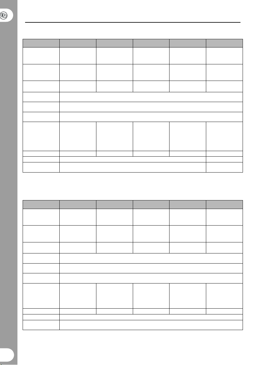
ELECTRICAL DATA | COMBIMASTER
CS A Low Voltage Single Phase Units
Model: CM12 CM25 CM37 CM55 CM75
Order Number:
2 pole
4 pole
Frame size:
2 pole
4 pole
Motor Output
Rating:
Operating Input
Voltage:
Operating Input
Frequency:
Output
Frequency:
Output Frequency
with Opm2 or
serial link:
2 pole
4 pole
Input Current: 1.8 A rms 3.2 A rms 4.6 A rms 6.2 A rms 8.2 A rms
Mains fuse: 10 A 16 A
Mains Lead crosssection
* [z] = filter option: U = Unfiltered, A = Class A filter, B = Class B filter.
Position 12 (shown as “.”) is for the construction type from the Siemens M11 catalogue.(ref.: E2002-K1711-
A201-A2-7600)
CS A Low Voltage Three Phase Units
Model: CM12/2 CM25/2 CM37/2 CM55/2 CM75/2
Order Number: *
2 pole
4 pole
Frame size: *
2 pole
4 pole
Motor Output
Rating:
Operating Input
Voltage:
Operating Input
Frequency:
Output
Frequency:
Output Frequency
with Opm2 or
serial link:
2 pole
4 pole
Input Current: 1.1 A rms 1.9 A rms 2.7 A rms 3.6 A rms 4.7 A rms
Mains fuse: 10 A
Mains Lead crosssection
* Note that these units are available Unfiltered only.
Position 12 (shown as “.”) is for the construction type from the Siemens M11 catalogue.(Ref.: see above)
1UA7053-2B[z]0.
1UA7060-4B[z]0.
56
63
0.12kW
0.16hp
0 – 100Hz
0 –140Hz
1UA7053-2BU1.
1UA7060-4BU1.
56
63
0.12kW
0.16hp
0 – 100Hz
0 –140Hz
1UA7063-2B[z]0.
1UA7070-4B[z]0.
63
71
0.25kW
0.33hp
0 – 100Hz
0 – 140Hz
1UA7063-2BU1.
1UA7070-4BU1.
63
71
0.25kW
0.33hp
0 – 100Hz
0 – 140Hz
1UA7070-2B[z]0.
1UA7073-4B[z]0.
71
71
0.37kW
0.49hp
1∅ AC 208 – 240 Vrms ± 10%
47 – 63 Hz
0 – 50Hz
0 – 100Hz
0 – 140Hz
2
1mm
1UA7070-2BU1.
1UA7073-4BU1.
71
71
0.37kW
0.49hp
3∅ AC 208 – 240 Vrms ± 10%
47 – 63 Hz
0 – 50Hz
0 – 100Hz
0 – 140Hz
2
1mm
1UA7073-2B[z]0.
1UA7080-4B[z]0.
71
80
0.55kW
0.73hp
0 – 100Hz
0 – 140Hz
1UA7073-2BU1.
1UA7080-4BU1.
71
80
0.55kW
0.73hp
0 – 100Hz
0 – 140Hz
1UA7080-2B[z]0.
1UA7083-4B[z]0.
80
80
0.75kW
1.0hp
0 – 100Hz
0 – 140Hz
1.5mm
1UA7080-2BU1.
1UA7083-4BU1.
80
80
0.75kw
1.0hp
0 – 100Hz
0 – 140Hz
2
14 © Siemens plc1999 | G85139-H1731-U400-D2
Page 16

CS A High Voltage Three Phase Units
Model: CM37/3 CM55/3 CM75/3 CM110/3 CM150/3
Order Number: *
2 pole
4 pole
Frame size:
2 pole
4 pole
Motor Output
Rating:
Operating Input
Voltage:
Operating Input
Frequency:
Output
Frequency:
Output Frequency
with Opm2 or
serial link:
2 pole
4 pole
Input Current: 2.2 A rms 2.8 A rms 3.7 A rms 4.9 A rms 5.9 A rms
Mains fuse: 10 A
Mains Lead crosssection
1UA7070-2B[zz].
1UA7073-4B[zz].
71
71
0.37kW
0.49hp
3∅ AC 380 – 500 V
100 Hz
140Hz
1UA7073-2B[zz].
1UA7080-4B[zz].
73
80
0.55kW
0.73hp
rms ± 10% (all units) 3∅ AC 380 – 480 Vrms ± 10% (filtered units only)
Torque derating required below 380Vrms
100Hz
140Hz
1UA7080-2B[zz].
1UA7083-4B[zz].
80
80
0.75kW
1.0hp
47 – 63 Hz
0 – 50Hz
100Hz
140Hz
2
1mm
1UA7083-2B[zz].
1UA7090-4B[zz].
80
90S
1.1kW
1.5hp
100Hz
140Hz
1UA7090-2C[zz].
1UA7096-4C[zz].
90S
90L
1.5kW
2.0hp
100Hz
140Hz
* [zz] = filter option: U = Unfiltered, A = Class A filter, B = Class B filter and mains voltage code: 2 = 380 – 500V,
3 = 460 – 500V/60Hz . Allowed combinations: A2, B2, U2 and U3.
Position 12 (shown as “.”) is for the construction type from the Siemens M11 catalogue. (Ref.: see above)
CS B High Voltage Three Phase Units
Model: CM150/3 CM220/3 CM300/3 CM400/3 CM550/3 CM750/3
Order Number: *
2 pole
4 pole
Frame size:
2 pole
4 pole
Motor Output
Rating:
Operating Input
Voltage:
Operating Input
Frequency:
Output
Frequency:
Output
Frequency with
Opm2 or serial
link:
2 pole
4 pole
Input Current: 3.5 A rms 4.7 A rms 6.4 A rms 10.0 A rms 12.2 A rms 16.0 A rms
Mains fuse: 10 A 16 A 20 A
Mains Lead
cross-section
* [zz] = filter option: U = Unfiltered, A = Class A filter, B = Class B filter and mains voltage code: 2 = 380 – 500V,
3 = 460 – 500V/60Hz . Allowed combinations: A2, B2, U2 and U3.
Position 12 (shown as “.”) is for the construction type from the Siemens M11 catalogue. (Ref.: see above)
1UA7090-
2B[zz].
1UA7096-
4B[zz].
90S
90L
1.5kW
2.0hp
3∅ AC 380 – 500 Vrms ± 10% (all units) 3∅ AC 380 – 480 Vrms ± 10% (filtered units only)
100 Hz
140Hz
1mm
1UA7096-
2B[zz].
1UA7106-
4B[zz].
100L
2.2kW
2.9hp
100Hz
140Hz
2
1UA7106-
2B[zz].
1UA7107-
4B[zz].
90L
100L
100L
3.0kW
4.0hp
Torque derating required below 380Vrms
47 – 63 Hz
0 – 50Hz
100Hz
140Hz
1.5mm
1UA7113-
2B[zz].
1UA7113-
4B[zz].
112M
112M
4.0kW
5.3hp
100Hz
140Hz
2
1UA7130-
2B[zz].
1UA7130-
4B[zz].
132S
132S
5.5kW
7.3hp
90Hz
140Hz
2.5mm
1UA7131-
2B[zz].
1UA7133-
2B[zz].
132S
132M
7.5kW
10.0hp
90Hz
140Hz
2
© Siemens plc 1999 | G85139-H1731-U400-D2 15
Page 17

ELECTRICAL DATA | MICROMASTER Integrated
CS A Low Voltage Single Phase Units
Model: MI12 MI25 MI37 MI55 MI75
Order Number: * 6SE9610-
7BF[y]0-Z=C87
6SE9611-
5BF[y]0-Z=C87
6SE9612-
0BF[y]0-Z=C87
6SE9612-
6BF[y]0-Z=C87
6SE9613-
4BF[y]0-Z=C87
Motor Output
Rating:
Operating Input
Voltage:
Operating Input
Frequency:
Output
Frequency:
Output Frequency
with Opm2 or
serial link:
Input Current: 1.8 A rms 3.2 A rms 4.6 A rms 6.2 A rms 8.2 A rms
Mains fuse: 10 A 16 A
Mains Lead crosssection
0.12kW
0.16hp
0.25kW
0.33hp
0.37kW
0.49hp
1∅ AC 208 – 240 Vrms ± 10%
47 – 63 Hz
0 – 50Hz
0 – 400Hz
2
1mm
0.55kW
0.73hp
0.75kW
1.0hp
1.5mm
* [y] = filter option: 1 = Unfiltered, 5 = Class A filter, 6 = Class B filter.
CS A Low Voltage Three Phase Units
Model: MI12/2 MI25/2 MI37/2 MI55/2 MI75/2
Order Number: * 6SE9610-7CF10-
Motor Output
Rating:
Operating Input
Voltage:
Operating Input
Frequency:
Output
Frequency:
Output Frequency
with Opm2 or
serial link:
Input Current: 1.1 A rms 1.9 A rms 2.7 A rms 3.6 A rms 4.7 A rms
Mains fuse: 10 A
Mains Lead crosssection
Z=C87
0.12kW
0.16hp
* Note that these units are available Unfiltered only.
6SE9611-5CF10-
Z=C87
0.25kW
0.33hp
6SE9612-0CF10-
Z=C87
0.37kW
0.49hp
3∅ AC 208 – 240 V
47 – 63 Hz
0 – 50Hz
0 – 400Hz
2
1mm
rms ± 10%
6SE9612-6CF10-
Z=C87
0.55kW
0.73hp
6SE9613-4CF10-
Z=C87
0.75kW
1.0hp
2
16 © Siemens plc1999 | G85139-H1731-U400-D2
Page 18

CS A High Voltage Three Phase Units
Model: MI37/3 MI55/3 MI75/3 MI110/3 MI150/3
Order Number: *
6SE9611-
1DF[y]0-Z=C87
6SE9611-
4DF[y]0-Z=C87
6SE9611-
8DF[y]0-Z=C87
6SE9612-
7DF[y]0-Z=C87
6SE9613-
7DF[y]0-Z=C87
Motor Output
Rating:
Operating Input
Voltage:
Operating Input
Frequency:
Output
Frequency:
Output Frequency
with Opm2 or
serial link:
Input Current: 2.2 A rms 2.8 A rms 3.7 A rms 4.9 A rms 5.9 A rms
Mains fuse: 10 A
Mains Lead crosssection
0.37kW
0.49hp
3∅ AC 380 – 500 Vrms ± 10% (all units) 3∅ AC 380 – 480 Vrms ± 10% (filtered units only)
0.55kW
0.73hp
0.75kW
1.0hp
47 – 63 Hz
0 – 50Hz
0-400Hz
2
1mm
1.1kW
1.5hp
1.5kW
2.0hp
* [y] = filter option: 1 = Unfiltered, 5 = Class A filter, 6 = Class B filter.
CS B High Voltage Three Phase Units
Model: MI150/3 MI220/3 MI300/3 MI400/3 MI550/3 MI750/3
Order Number: * 6SE9613-
Motor Output
Rating:
Operating Input
Voltage:
Operating Input
Frequency:
Output
Frequency:
Output
Frequency with
Opm2 or serial
link:
Input Current: 3.5 A rms 4.7 A rms 6.4 A rms 10.0 A rms 12.2 A rms 16.0 A rms
Mains fuse: 10 A 16 A 20 A
Mains Lead
cross-section
7DD[y]0-
Z=C87
1.5kW
2.0hp
3∅ AC 380 – 500 Vrms ± 10% (all units) 3∅ AC 380 – 480 Vrms ± 10% (filtered units only)
1mm
6SE9615-
8DD[y]0-
Z=C87
2.2kW
2.9hp
2
6SE9617-
3DD[y]0-
Z=C87
3.0kW
4.0hp
47 – 63 Hz
0 – 50Hz
0-400Hz
1.5mm
6SE9621-
1DD[y]0-
Z=C87
4.0kW
5.3hp
2
6SE9621-
3DD[y]0-
Z=C87
5.5kW
7.3hp
2.5mm
6SE9621-
7DD[y]0-
Z=C87
7.5kW
10.0hp
2
* [y] = filter option: 1 = Unfiltered, 5 = Class A filter, 6 = Class B filter.
PARAMETER SUMMARY LIST
This list is applicable for operation using Opm2 – Clear Text Display (optional).
● = Parameter can be changed during operation.
✩✩✩ = Value depends on the rating of the motor.
© Siemens plc 1999 | G85139-H1731-U400-D2 17
Page 19

Parameter Function Default
Parameter Function Default
P000 Operating display -
P001 ● Display mode 0
P002 ● Ramp up time (seconds) 10.00
P003 ● Ramp down time (seconds) 25.00
P004 ● Smoothing (seconds) 0.0
P005 ● Digital frequency setpoint (Hz) 50.00
P006 Frequency setpoint source selection 1
P007 Keypad control 0
P009 ● Parameter protection setting 0
P011 Frequency setpoint memory 0
P012 ● Minimum motor frequency (Hz) 0.00
P013 ● Maximum motor frequency (Hz) 50.00
P014 ● Skip frequency 1 (Hz) 0.00
P015 ● Automatic restart after mains failure 0
P016 ● Start on the fly 0
P017 ● Smoothing type 1
P018 ● Automatic restart after fault 0
P019 ● Skip frequency bandwidth (Hz) 2.00
P020 Flying start ramp time (seconds) 25.00
P021 ● Minimum analogue frequency (Hz) 0.00
P022 ● Maximum analogue frequency (Hz) 50.00
P023 ● Analogue input type 2
P024 ● Analogue setpoint addition 0
P027 ● Skip frequency 2 (Hz) 0.00
P028 ● Skip frequency 3 (Hz) 0.00
P029 ● Skip frequency 4 (Hz) 0.00
P031 ● Jog frequency right (Hz) 5.00
P032 ● Jog frequency left (Hz) 5.00
P033 Jog Ramp Up time (V3.00) 10.00
P034 Jog Ramp Down time (V3.00) 10.00
P035 Reverse motor direction 0
P041 ● Fixed frequency 1 (Hz) 5.00
P042 ● Fixed frequency 2 (Hz) 10.00
P043 ● Fixed frequency 3 (Hz) 15.00
P044 ● Fixed frequency 4 (Hz) 20.00
P045 Inversion fixed setpoints for fixed
P046 ● Fixed frequency 5 (Hz) 25.00
P047 ● Fixed frequency 6 (Hz) 30.00
P048 ● Fixed frequency 7 (Hz) 35.00
P050 Inversion fixed setpoints for fixed
P051
P052 Selection control function (DIN2 –
P053 Selection control function (DIN3 –
P056 Digital input debounce time 0
P058 ● RUN command delay (seconds) 0.0
P061 Selection relay output RL1 6
P062 Electro-mechanical brake option
P063 External brake release delay
P064 External brake stopping time
P065 Current threshold for relay (A) 1.0
P071 ● Slip compensation (%) 0
P072 ● Slip limit (%) 500
P073 ● DC injection braking (%) 0
P074 ● I2t motor derating 0
PO76 Pulse Frequency 0 or 2
P077 Control mode 0
P078 ● Continuous boost (%) 50
P079 ● Starting boost (%) 0
P081 Nominal frequency for motor (Hz)
P082 Nominal speed for motor (RPM)
P083 Nominal current for motor (A)
P084 Nominal voltage for motor (V)
frequencies 1 – 4
frequencies 5 – 7
Selection control function (DIN1 –
terminal 5) fixed frequency 3 or binary
fixed frequency bit 0
terminal 6) fixed frequency 2 or binary
fixed frequency bit 1
terminal 7) fixed frequency 1 or binary
fixed frequency bit 2
control
(seconds)
(seconds)
0
0
1
2
10
0
1.0
1.0
✩✩✩
✩✩✩
✩✩✩
✩✩✩
18 © Siemens plc1999 | G85139-H1731-U400-D2
Page 20

Parameter Function Default
Parameter Function Default
P085 Nominal power for motor (kW/hp)
P086 ● Motor current limit (%) 150
P087 Motor PTC enable 0
P089 ●
P091 ● Serial link slave address 0
P092 ● Serial link baud rate 6
P093 ● Serial link timeout (seconds) 0
P094 ● Serial link nominal system setpoint
P095 ● USS compatibility 0
P099 ● Communication adapter type 0
P101 ● Operation for Europe or North America 0
P111 Inverter power rating (kW/hp)
P112 Inverter type 8
P113 COMBIMASTER model -
P121 Enable/disable RUN button 1
P122 Enable/disable FORWARD/REVERSE
P123 Enable/disable JOG button 1
P124
P125 Reverse direction inhibit 1
P131 Frequency setpoint (Hz) -
P132 Motor current (A) -
P133 Motor torque (% nominal torque) -
P134 DC link voltage (V) -
P135 Motor RPM -
P137 Output voltage (V) -
P140 Most recent fault code -
P141 Most recent fault code –1 -
P142 Most recent fault code –2 -
P143 Most recent fault code –3 -
P151 ● Green LED function 4
Stator resistance (Ω)
(Hz)
button
Enable/disable ∆ and ∇ buttons
✩✩✩
✩✩✩
50.00
✩✩✩
1
1
P152 ● Yellow LED function 5
P201 PI closed loop mode 0
P202 ● P gain (%) 1.0
P203 ● I gain (%) 0.00
P205 ● Sample interval (x 25 ms) 1
P206 ● Transducer filtering 0
P207 ● Integral capture range (%) 100
P208 Transducer type 0
P210 Transducer reading (%) -
P211 ● 0% setpoint 0.00
P212 ● 100% setpoint 100.00
P220 PI frequency cut-off 0
P331 Analogue mode 2
P332 Fine adjustment (%) 10
P723 State of digital inputs -
P845
P910 ● Local/Remote mode 0
P922 Software version -
P923 ● Equipment system number 0
P930 Most recent fault code -
P931 Most recent warning type -
P944 Reset to factory default settings 0
P971 ● EEPROM storage control 1
P986 Relay Output 0
Motor current limt for flying start
(V3.00)
50
WARNING
Please refer to the Reference Manual before changing any parameters.
© Siemens plc 1999 | G85139-H1731-U400-D2 19
Page 21

For Technical Support Information,
and to submit your suggestions
for improvements, see our Web Site:
http://www.con.siemens.co.uk
Herausgegeben vom
Bereich Automatisierungsund Antriebstechnik (A&D)
Geschäftsgebiet Standard Drives
Postfach 3269, D-91050 Erlangen
*6SE9996-0XA36*
6SE9996-0XA36
*H1731-U400-D2*
G85139-H1731-U400-D2
August 1999
English
Order Number: 6SE9996-0XA36
Siemens plc
Automation & Drives
Standard Drives Division
Siemens House
Varey Road
Congleton CW12 1PH
Änderungen vorbehalten
Specification subject to change without prior notice
 Loading...