

Page 1
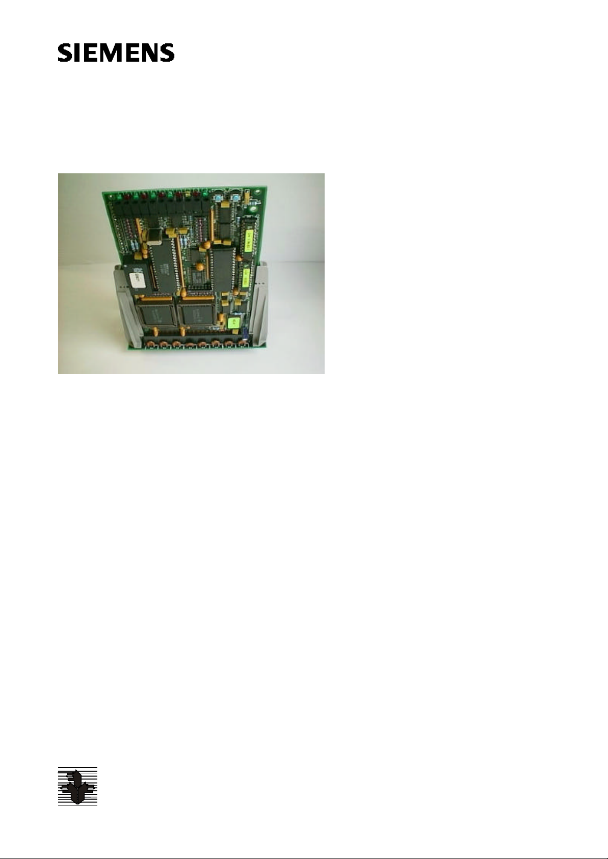
Manual LMSmodular Hardware
Section 2
Cerberus LMSmodular
Gateway GW-21
Technical Manual
Cerberus
Security
for People
and Assets
Siemens Building Technologies
Cerberus Division
Page 2

Data and design subject to change
without notice. / Supply subject to
availability.
© Copyright by
Siemens Building Technologies AG
We reserve all rights in this document
and in the subject thereof. By acceptance of the document the recipient
acknowledges these rights and undertakes not to publish the document
nor the subject thereof in full or in
part, nor to make them available to
any third party without our prior express written authorization, nor to use
it for any purpose other than for which
it was deli vered to him.
Page 3

1 Introduction .................................................................................. 1
1.1 Scope of this document .................................................................... 2
1.2 Related publications ........................................................................ 2
2 Product Description....................................................................... 3
2.1 CPU board ..................................................................................... 3
2.2 The expansion board....................................................................... 4
2.3 The connection board ...................................................................... 5
2.4 The assembled gateway................................................................... 5
2.5 Some network configuration.............................................................. 6
3 Hardware Installation ..................................................................... 9
3.1 Inside the CS4 ................................................................................ 9
3.2 Power supply.................................................................................. 9
3.3 Inside the CS11 .............................................................................10
4 CPU Board Configuration ..............................................................11
4.1 Introduction ...................................................................................11
4.2 Configuration by DIL-Switches .........................................................12
4.2.1 Subsystem setting..........................................................................12
4.2.2 Cerban vitality telegram...................................................................13
4.3 Configuration by Flash EPROM........................................................13
4.4 Two level network ...........................................................................13
4.4.1 Ciphering option .............................................................................14
5 Baud Rates...................................................................................15
6 Cables and Connections...............................................................16
6.1 Connection to LMS.........................................................................16
6.2 Connection to GW-20 .....................................................................17
6.3 Gateway to subsystem connection....................................................17
6.4 Gateway to CMX connection............................................................18
6.5 Gateway to Cerpass Connection/Interface CC30-CK3003....................18
6.6 Gateway to Transliner.....................................................................19
7 Three Configuration Examples......................................................20
7.1 Example no. 1................................................................................20
7.2 Example no. 2................................................................................21
7.3 Example no. 3................................................................................22
8 Troubleshooting...........................................................................22
9 Appendix A: STT/GW-21 Connection.............................................23
9.1 First case......................................................................................23
9.2 Second case ..................................................................................24
9.3 Example no. 1................................................................................25
9.4 Example no. 2................................................................................26
10 Appendix B: Firmware Version......................................................26
11 Appendix C: DIL-Switches Description .........................................27
12 Appendix D: GW-21 Rev. A............................................................28
12.1 The connection board .....................................................................28
12.2 Inside the CS4 ...............................................................................30
12.3 Connection to LMS.........................................................................31
12.4 Connection to GW-20 .....................................................................33
12.5 Gateway to subsystem connection....................................................34
12.6 Gateway to CMX / CF9003 connection..............................................35
13 Appendix E: Safety Instructions....................................................36
Siemens Building Technologies
Cerberus Division
I
06.2000
Page 4

Page 5

1 Introduction
i
The GW-21 Gateway provides the following main functions:
1. interface between subsystems and operator workstations (LMS or a foreign system);
2. interactions among subsystems:
3. protocol conversions.
The GW-21 gateway is composed by one CPU board with serial communication capability to which can be connected an optional expansion board with additional serial lines
in a piggyback configuration.
In a two level network architecture, the GW-21 can be used as communication layer
that connect the subsystems to a higher level GW-20.
The GW-21 complies with the latest European Union standards for emission and immunity to electromagnetic disturbances. It is designed to replace the GW-01.
GW-21 rev. B has a new connection board and galvanic isolation on power supply for
CS11 compat ibility.
Old GW21 rev. A is still available in appendix D.
Two kinds of hardware configurations are foreseen:
GW-21.06
This configuration has 6 serial lines; it requires CPU board and an additional expansion
board with two more asynchronous serial lines. Using this configuration you can connect up to four subsystems to one or two workst ations.
GW-21.04
This configuration has 4 serial lines; it is composed by the CPU board that has onboard 4 communication lines. Up to three control panels can be connected to one
workstation, or it can connect two workstations and two su bsystems.
1
Siemens Building Technologies
Cerberus Division
E1481b
06.2000
Page 6

1.1 Scope of this document
This manual is intended as a guide for planning, installation and service personnel of
Cerberus danger management systems which use GW-21 device.
All necessary information to install an LMS gateway are listed in this manual.
The manual is divided into 8 chapters and 4 annexes; a Table of Contents and an Index
allow easy referencing to the arguments.
Chapter 1 is an introduction to the manual;
Chapter 2 describes the product and the available configurations;
Chapter 3 shows how to install the gateway inside the CS4/CS11 and how to power it;
Chapter 4 describes the CPU board;
Chapter 5 explains how to set the baud rates and shows the suggested or compulsory
baud rates for the various subsystems that can be connected to the GW-21;
Chapter 6 shows the cable and connection among the GW-21 and the other devices it
can be connected to;
Chapter 6 contains three examples of gateway configuration
Chapter 7 describes how you can identify problems that can possibly arise.
Appendix A explains the use of STT subsystem, manufactured by Cerberus Guinard,
in conjunction with the Gateway GW-21.
Appendix B lists the firmware versions compatible with LMS software versions, as well
as the limits about subsystems managed.
Appendix C contains a summary of DIL-Switch settings.
Appendix D describes the previous version of GW-21 board and connection cables.
Appendix E describes the safety instructions.
They are included here for reference.
1.2 Related publications
The following documents could be useful in dealing with GW-21 gateway and understanding how it relates to other pieces of the LMS network:
§ GW-20 Technical manual e1478
§ CMX Technical manual e1110
§ CF9003 Technical Manual e1762
§ LMSmodular User Manual e1865
§ LMSmodular Configuration Guide e1863
§ LMSmodular Configuration Reference e1864
§ LMSmodular Installation Manual e1862
2
Siemens Building Technologies
Cerberus Division
E1481b
06.2000
Page 7
2 Product Description
S3
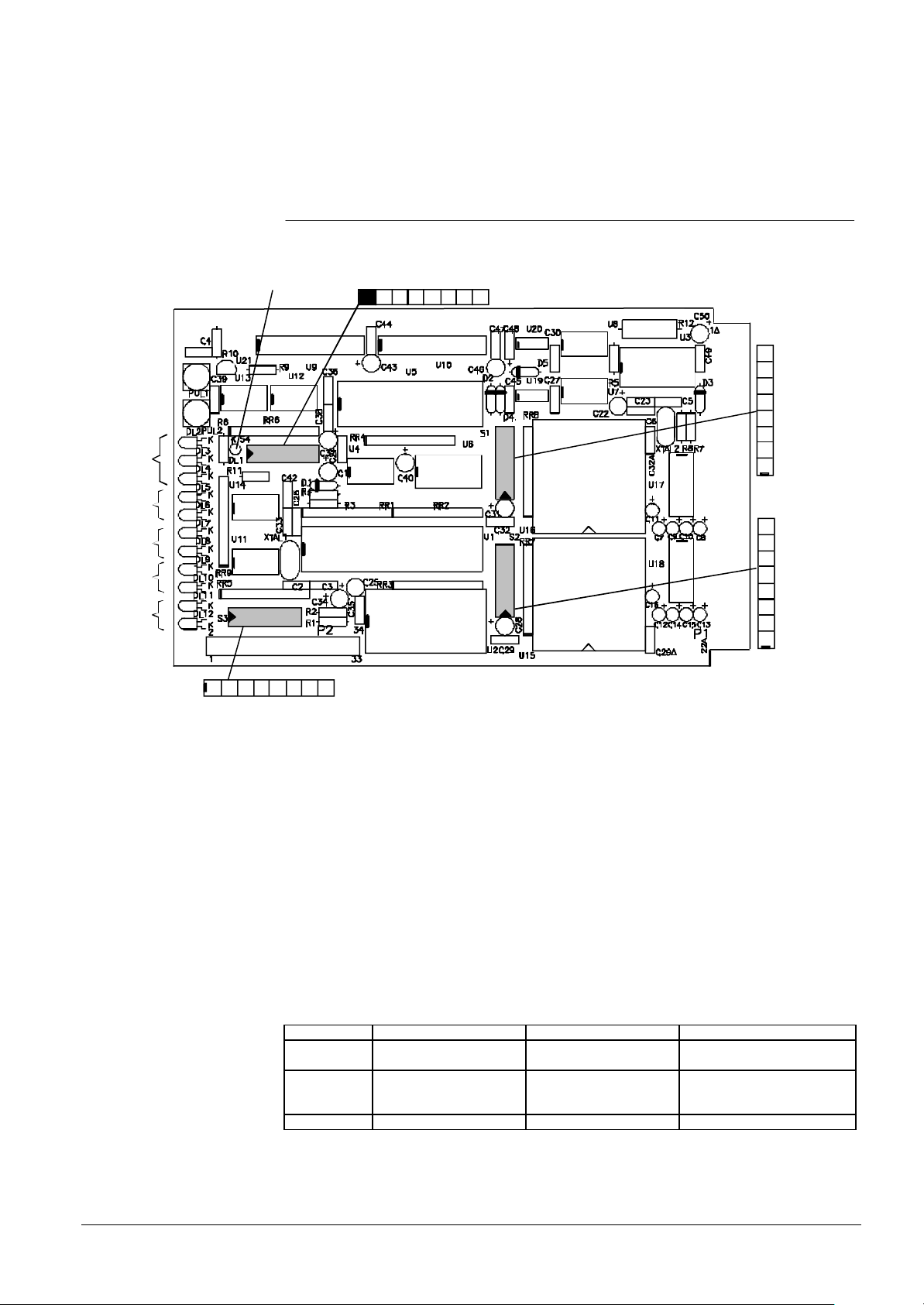
2.1 CPU board
The CPU board is the main board. It must be present in any gateway GW-21, aside
from its configuration.
service pin LED
S4
NC
2 87643 5
Reset
Service
Diagnostic
UART1
UART2
UART3
UART4
RX
TX
RX
TX
RX
TX
RX
TX
1 2 87643 5
8
7
6
5
4
3
2
1
8
7
6
5
4
3
2
1
S1
S2
Flash EPROM
RAM
CPU
RTC
Neuron
Chip
UART
UART
Fig. 1 The CPU board
On this board there are:
§ the CPU, the RAM and Flash EPROM
§ the Real Time Clock (RTC)
§ two UART chips, that manage the four GW-21 serial lines
§ the Neuron Chip, that lets the GW-21 to communicate with the Lon Work network
§ four DIL switch blocks (S1 - S4), used to configure the GW-21 as de scribed later
§ one reset push-button, used to reset the board
§ one service push-button, to send the service signal to the Neuron Chip
§ four sets of two LEDs. These LEDs show the status of UART RX/TX lines.
§ three LEDs used for diagnostic purposes.
For GW-21, the CD95800 board is configured as type 3 (check label on the RTC component).
The three diagnostic LEDs marked LD1, LD2 and LD3 have the following meaning:
LD1 (green) Firmware vitality failure or
LD2 (red) Download failed OK Slow (1Hz): RAM test failed
LD3 (yellow) - - -
ON OFF Blinking
out of memory jump
Firmware vitality failure or
out of memory jump
Firmware vitality OK
Fast (4Hz): wrong configuration
or download in progress
Tab. 1
Siemens Building Technologies
Cerberus Division
3
E1481b
06.2000
Page 8
UART6
UART5
TX
RX
TX
RX
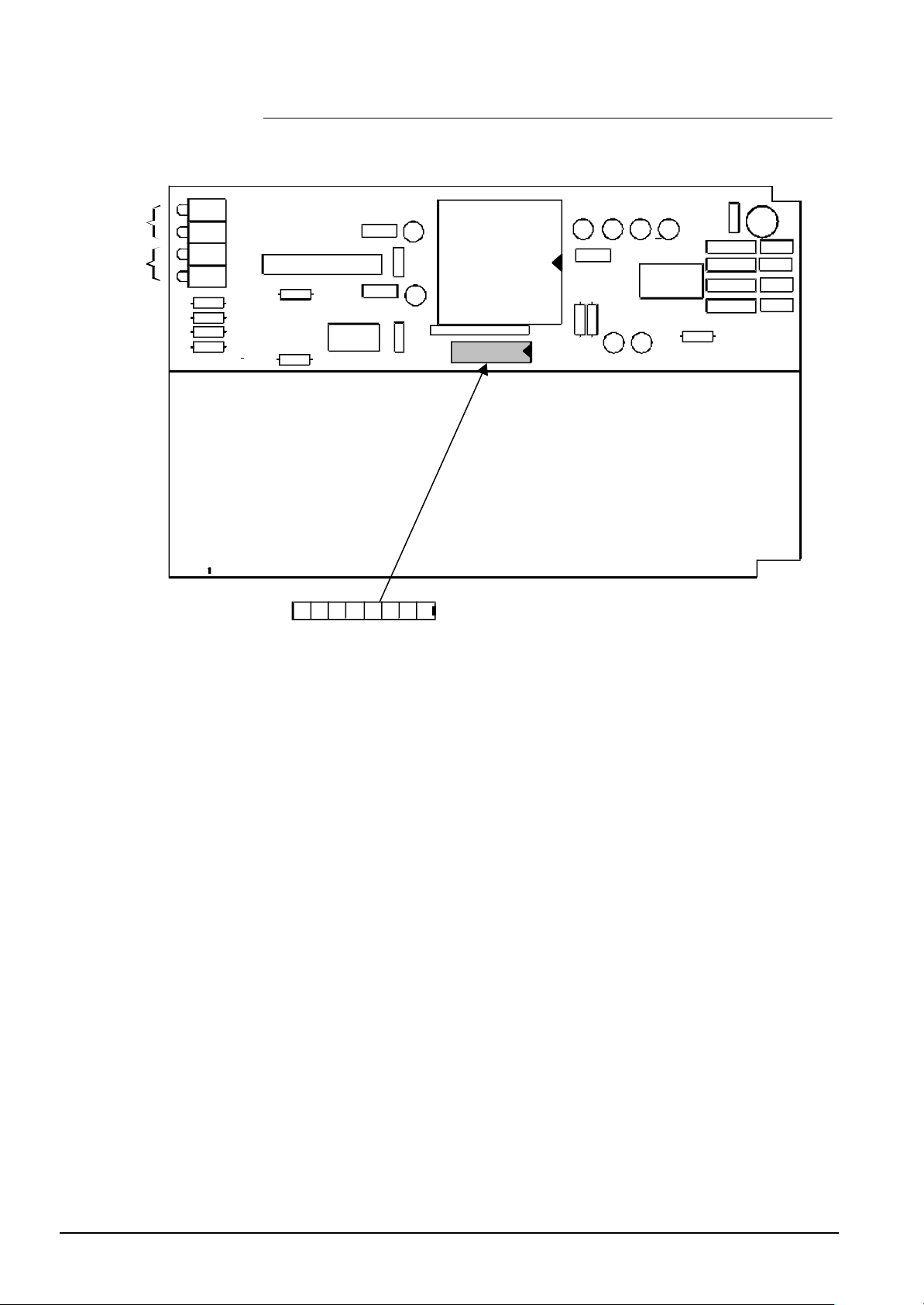
2.2 The expansion board
The expansion board supplies two asynchronous serial lines. It is mounted piggy back
on the CPU board.
DL1
DL 2
DL 3
DL 4
UART
S5 128 7 6 4 35
Fig. 2 The expansion board
(S1onCD95802)
4
Siemens Building Technologies
Cerberus Division
E1481b
06.2000
Page 9
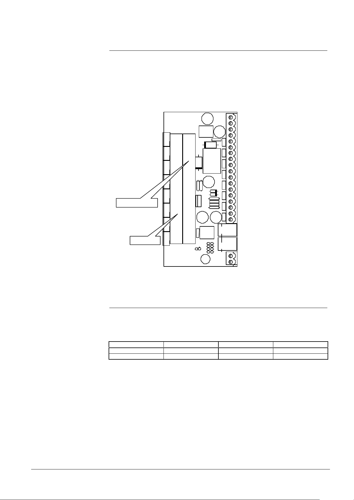
2.3 The connection board
GND
RX6
TX6
GND
RX5
TX5
GND
RX4
TX4
GND
RX3
TX3
GND
RX2
TX2
GND
RX1
TX1
+
-
Vdc
The connection board has two connectors to insert the CPU and I/O board in.
All the UARTs, from 1 to 6, are accessible through screw connectors located on the
right side of the connection board. Only the TX, RX and GND signals are available.
UARTs 5 and 6, if the expansion board is installed, are accessible on the same connector.
In the lower right corner of the connection board there is the power supply block with
two pins marked + and -. You must connect here the voltage source (10 to 30 V d.c.).
Expansion board
CPU board
Fig. 3 The connection board
2.4 The assembled gateway
The three components (the CPU board, the Expansion board, the Connection board)
can be assembled in two different ways.
The following table shows these configurations:
GW-21.06 x x x
GW-21.04 x x
Tab. 2
CPU board Expansion board Connection Board
Siemens Building Technologies
Cerberus Division
5
E1481b
06.2000
Page 10
2.5 Some network configuration
One or two workstation
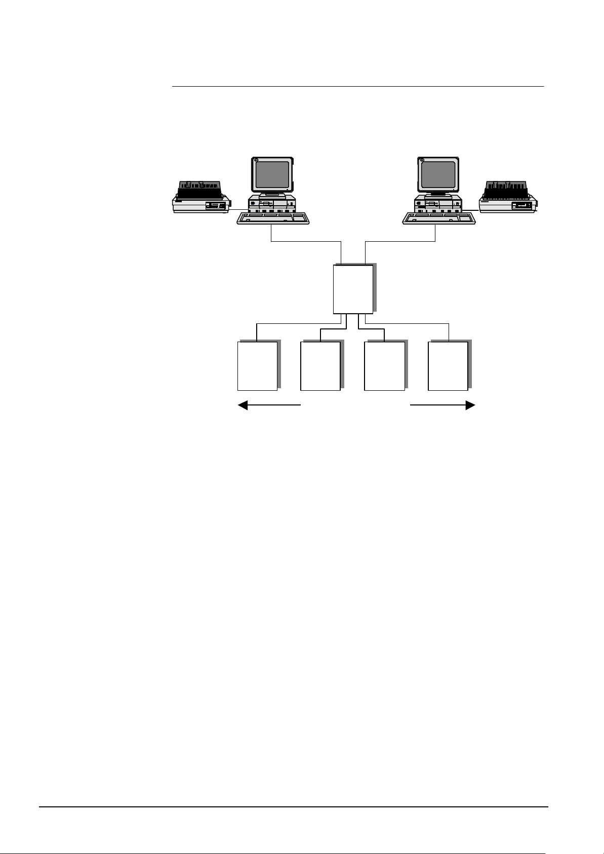
The most common network configuration the GW-21 gateway is inserted in is that
shown in Fig. 4 to the gateway are connected one or more (up to 4 for a GW-21.06)
subsystems. One or two LMS workstations are connected to the gateway and monitor
the subsystems. This configuration is named one level network.
GW-21.xx
Control
Panel
Control
Panel
1 to 4 contol panels
Fig. 4 The one level network configuration
Control
Panel
Control
Panel
6
Siemens Building Technologies
Cerberus Division
E1481b
06.2000
Page 11
Control
Panel
Control
Control
Control
Panel
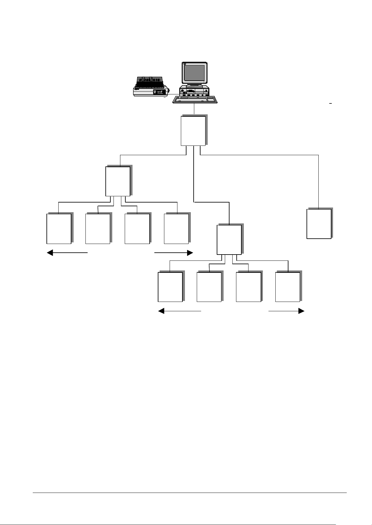
A more complicated configuration is shown in Fig. 5 this network topology, the so called
two level network, the GW-21 is connected to a GW-20 that acts as a gateway concentrator.
GW-20
GW-21.xx
Control
Panel
Panel
GW-21.xx
Panel
1 to 4 contol panels
Fig. 5 The two level network
Control
Panel
Control
Panel
1 to 4 contol panels
Control
Panel
Control
Panel
Siemens Building Technologies
Cerberus Division
7
E1481b
06.2000
Page 12
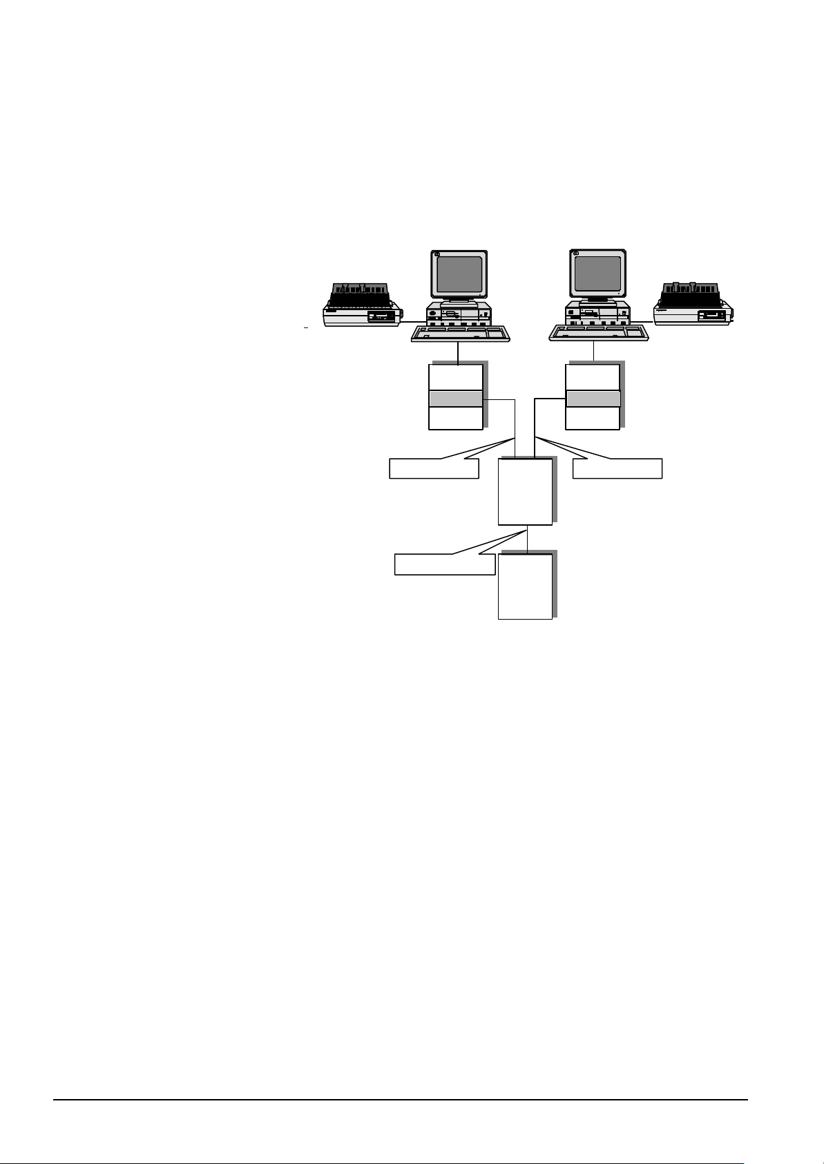
Fig. 6 shows a less usual configuration, used only in plants in which an high level of re-
CMSL protokol
CMSL protokol
CERBAN protokol
dundancy is required. In this configuration, the GW-21.xx gateway acts as an intelligent
line splitter and protocol converter: the signals coming from the subsystem(s) are converted from Cerban to CMSDL protocol and routed toward two supervisor systems. The
GW-20 that receive the messages should be equipped with Net-M Pad. The messages
are treated in a completely independent way by the two supervising systems connected
to the GW-20.
CMS/LMS monitoring system CMS/LMS monitoring system
Fig. 6 The redundant configuration
GW-20
Net-M Pad Net-M Pad
GW-21
CSxx
GW-20
8
Siemens Building Technologies
Cerberus Division
E1481b
06.2000
Page 13
3 Hardware Installation
3.1 Inside the CS4
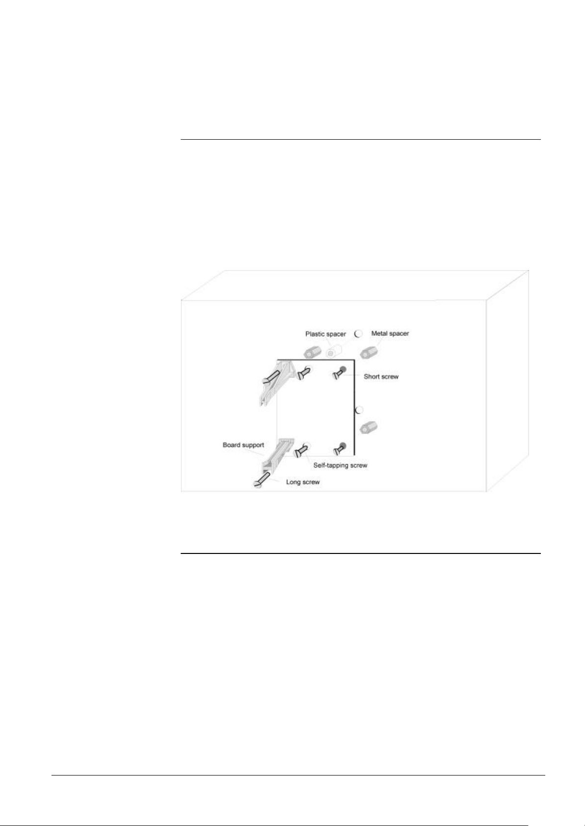
In the CS4 intrusion detection control unit the gateway can be mounted on some of the
standard housings.
You need:
§ 2 plastic spacers
§ 2 self-tapping screws
§ 4 metal spacers
§ 2 short screws
§ 2 long screws
§ 2 board supports
Siemens Building Technologies
Cerberus Division
Fig. 7
3.2 Power supply
The gateway GW-21 is powered using the connectors CN1 or CN2 located on the connection board (Please refer to Fig. 3). It does not matter which connector you use for
power supply connection, but pay attention to pin polarities.
The supply voltage must be in the range 10 to 30 V d.c.
9
E1481b
06.2000
Page 14
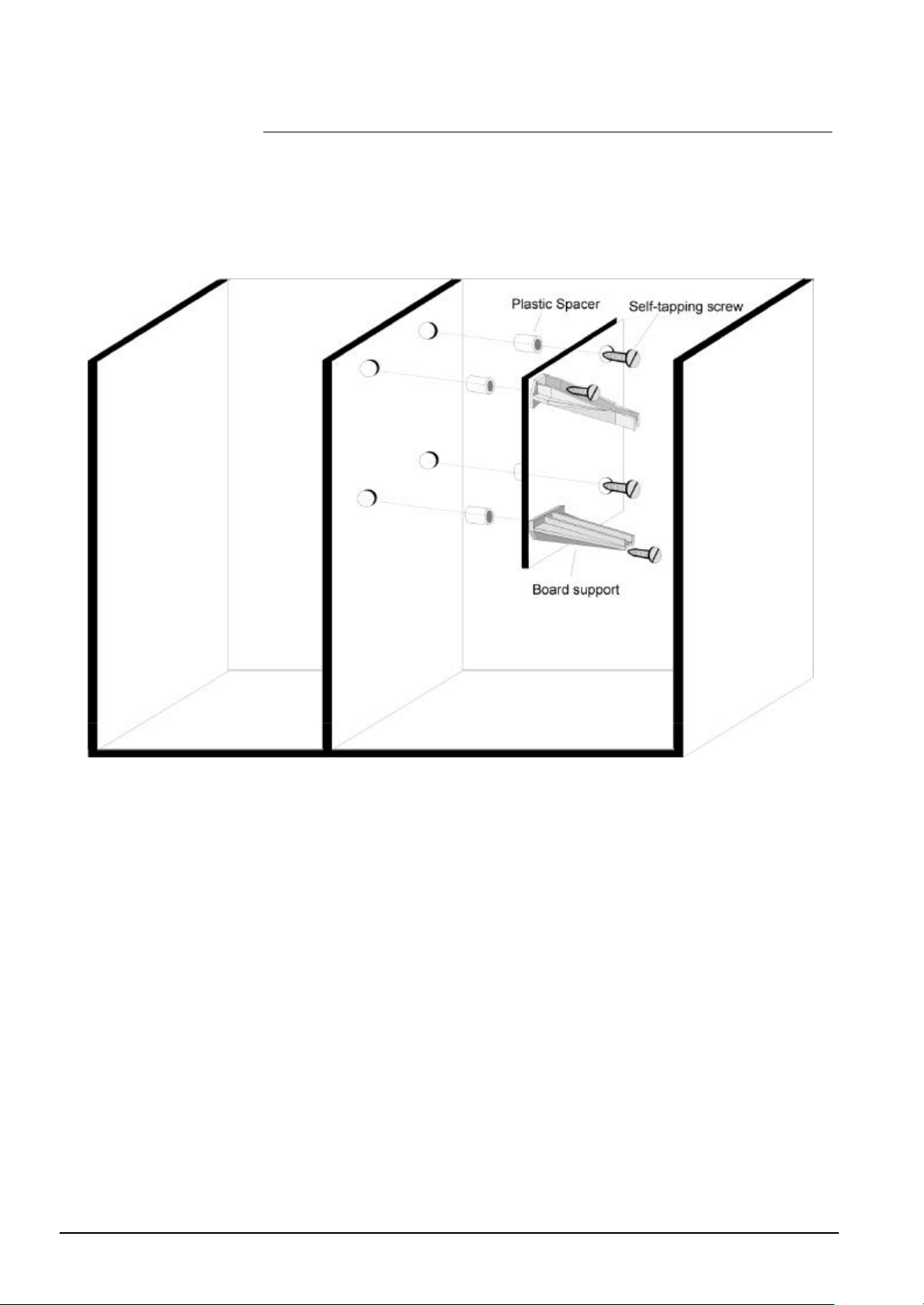
3.3 Inside the CS11
In the CS11 intrusion detection control unit the gateway can be mounted on some of
the standard housings.
You need:
§ 4 plastic spacers
§ 4 self-tapping screws
§ 2 board supports
Fig. 8
10
Siemens Building Technologies
Cerberus Division
E1481b
06.2000
Page 15
4 CPU Board Co nfiguration
i
4.1 Introduction
On the CPU board you can find four groups of DIL-Switches, numbered from S1 to S4.
A fifth block can be found on the expansion board if it is installed. The DIL-Switches replace the jumpers that were used on the GW-01 for configuration purposes.
We will refer in this document to DIL-Switches with a double numbering convention: the
fist number refers to the block the DIL-Switch belongs to, the second number is the
switch position inside the block. Therefore, S1-2 means “the second DIL-Switch on the
first block”.
Gateway configuration
Gateway configuration can be done in two alternative ways:
§ by DIL-Switches
§ by Flash EPROM
Flash EPROM configuration is required when the gateway has to handle interactions
among subsystems. The Flash EPROM can be configured using a proper software tool
provided by Cerberus Dati.
Gateway data-link
The Gateway GW-21 can be connected to various devices, and namely to:
§ CS11 fire detection control unit, manufactured by Cerberus
§ CS4 intrusion detection control unit, manufactured by Cerberus
§ CC60 gas detection unit, manufactured by Cerberus
§ Cerberus Dati CMX/CF9003, that allow I/O of digital signals
§ Westinghouse Electronics access control devices which use the SEEP protocol
§ Cerberus Guinard STT
§ CCTV switching matrix, MX series, manufactured by Comerson.
§ 8x00 Allegiant CCTV switcher control system, manufactured by Burle.
§ MK7022 Cerloop Interface
§ Devices supplied by third parties that use Cerberus Dati Standard Protocol
(CDDL/CDSF)
§ CC30 Door Controller manufactured by Cerberus Ristow
§ Transliner intrusion detection control unit by Cerberus Ristow
Unfortunately , due to limited ROM space not all these devices can share the same
gateway. Different firmware EPROM are needed to accommodate the most common
and useful combinations of these devices. Appendix B lists the combinations available
(please also refer to latest LMS News).
A set of EPROM programs that allow connection of peripheral devices is called soft-
ware link. All GW-21 links and its firmware are located on a single Flash EPROM.
11
Siemens Building Technologies
Cerberus Division
E1481b
06.2000
Page 16
What to configure
The switch S1-1 is used to discriminate between Flash EPROM configuration or DILSwitches configuration. If it is set OFF, the DIL-Switches are irrelevant for configuration
purposes. Otherwise, they set the GW-21 parameters as described in the following
section.
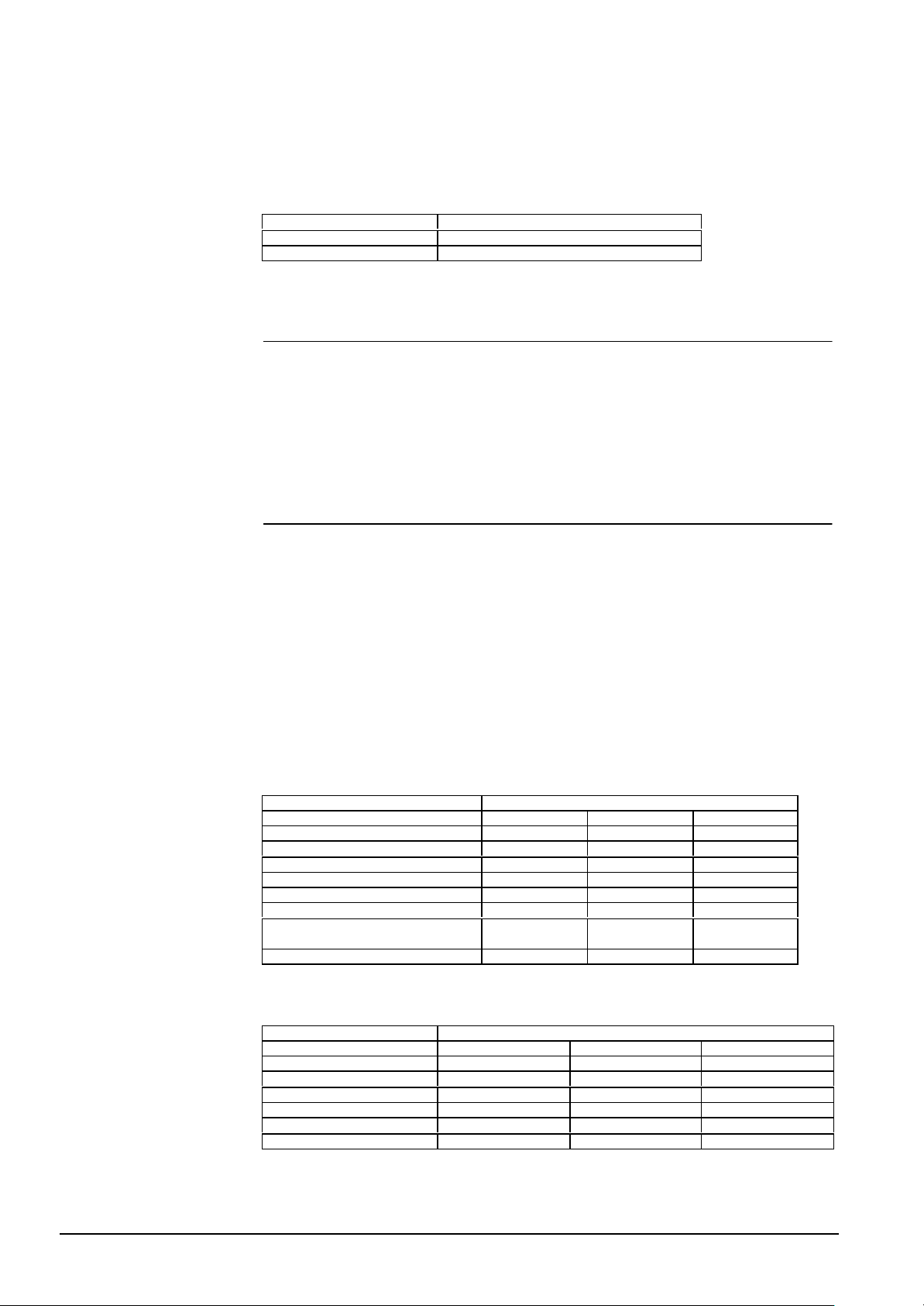
S1-1 Function
ON Configuration by DIL-Switches
OFF Configuration by Flash EPROM
Tab. 3
4.2 Configuration by DIL-Switches
To configure the CPU board by DIL-Switches, the DIL-Switch S1-1 has to be set ON.
When you configure the GW-21 by DIL-Switches you have to:
§ specify which subsystems is connected to each gateway UART;
§ set the baud rate for the installed protocols;
§ set the Cerban vitality telegram option;
§ set the ciphering option, when needed.
4.2.1 Subsystem setting
To specify the type of subsystem connected to each UART you have to use the following two tables.
First of all define the DIL-Switches settings: look at Tab. 4 and identify the settings for
the subsystem type you wish to connect to GW-21. For instance, a CS11 requires the
(OFF, OFF, ON) setting.
Then, using the Tab. 5, find out the DIL-Switches that are used by the UART to which
the subsystem is connected; set the three DIL-Switches as specified.
In a GW-21 up to six UART are available and so 18 DIL-Switches are reserved. They
are divided into groups of three. Each group can assume the value corresponding to
the subsystem you want connect.
You must remember that you can have up to table 4 subsystems and up to 2 LMS
lines. These values cannot be exceeded.
12
Siemens Building Technologies
Cerberus Division
SUBSYSTEM DIL-Switches
no subsystem OFF OFF OFF
CS11/CZ10/CC60(Cerban) OFF OFF ON
CS4/CZ12(Cerban) OFF ON OFF
CMX(CF9003 (CMX-DL) OFF ON ON
CCTV Burle or MK7022 (ISO1745 (*) ON OFF OFF
STT (Cerban) ON OFF ON
WSE ACU (SEEP) or CDDL/CDSF or
CC30 (Certalk) or Transliner (Size) (*)
LMS /Two level network ON ON ON
MSB LSB
ON ON OFF
(*) depends on Firmware configuration
Tab. 4 Subsystem selection
UART DIL-Switches
1 S1.6 S1.5 S1.4
2 S2.4 S2.3 S2.2
3 S3.2 S3.1 S2.8
4 S3.8 S3.7 S3.6
5 (on expansion board) S4.7 S4.6 S4.5
6 (on expansion board) S5.5. S5.4 S5.3
MSB LSB
Tab. 5 Association UART/subsystem
E1481b
06.2000
Page 17
i
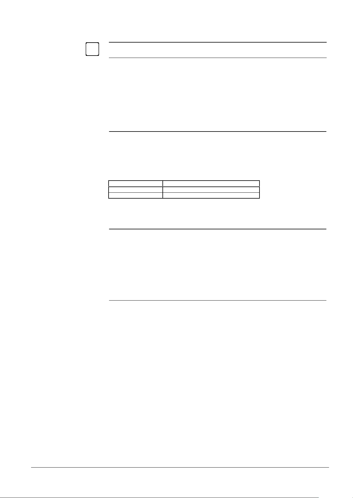
If only one LMS workstation is foreseen, it can use any of the six UART available;
if two LMS workstation are installed, they MUST occupy UART 1 and 2.
The subsystem network address (to be specified in the LMS configuration software) is
automatically assigned to the UARTs, from the lowest to the highest, starting from network address 0. UARTs used by LMS are of course skipped (see the examples in Section 6.5).
You must then set the communication baud rate according to the suggested protocol/baud rates (See section 5).
4.2.2 Cerban vitality telegram
The DIL-Switch S1-2 has the optional function to filter the Cerban vitality telegram; the
DIL-Switch is valid for all of the Cerban line which are defined on the gateway.
The only reason to filter the vitality telegram is to limit the traffic of messages to the
LMS station(s). Note that if the vitality check is enabled at LMS level, then this DILSwitch must be set to ON, else LMS will generate false fault events.
S1-2 Function
OFF Vitality telegram filtered
ON Vitality telegram not filtered
Tab. 6 Cerban vitality telegram filtering
4.3 Configuration by Flash EPROM
If you have the configuration EPROM, you have to set OFF the DIL-Switch S1-1. The
default configuration for this DIL-Switch set is for EPROM not installed, so you actually
have only to verify the settings.
Even if the Flash EPROM configuration is enabled, you must set the communication
baud rate with subsystems using the DIL-Switches and according to the suggested
protocol/baud rates (See section 5).
4.4 Two level network
In the two level network or in the redundant configuration (shown in Fig. 5 and Fig. 6)
the gateway GW-21 is connected to a GW-20. You have to set the DIL switches for the
protocol selection of the used UARTs as specified in Tab. 4.
You must then set the communication baud rate according to the suggested protocol/baud rates (See section 5).
13
Siemens Building Technologies
Cerberus Division
E1481b
06.2000
Page 18
4.4.1 Ciphering option
The DIL-Switch S1.3 have the optional function to enable the ciphering performance.
S1.3 Function
OFF Ciphering disabled
ON Ciphering enabled
Tab. 7
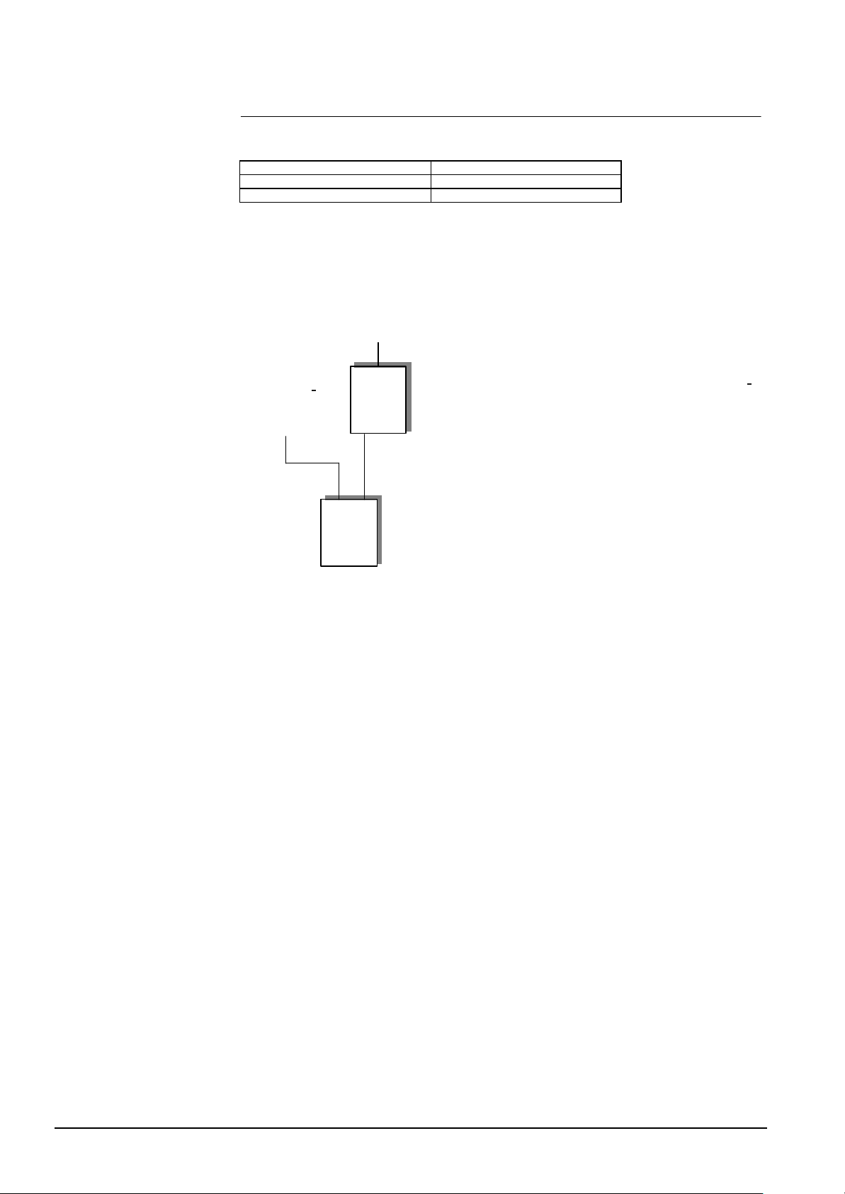
The ciphering applies only to two level network, in the communications between the
GW-20 and the GW-21.
Note about the ciphering : To implement the following configuration
LMS
GW-20
Local LMS
GW-21
Fig. 9 .
you must set the DIL-Switch S1.3 OFF because it is not allowed to have on the same
gateway one ciphered line and one non-ciphered line.
14
Siemens Building Technologies
Cerberus Division
E1481b
06.2000
Page 19
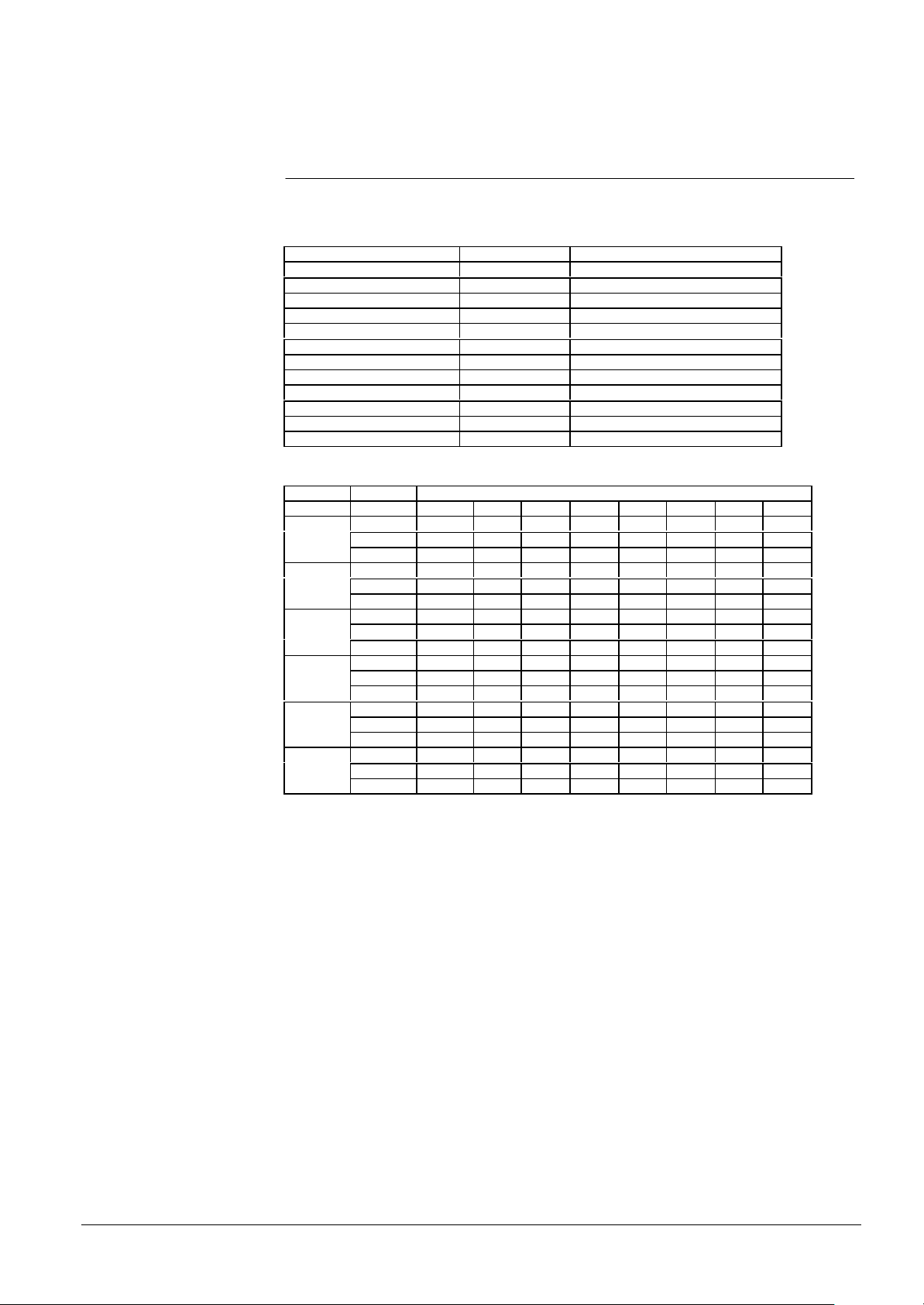
5 Baud Rates
The following baud rates apply to the subsystems connected either to the CPU or the
expansion board.
SUBSYSTEM SETTING SUGGESTED BAUD RATE
CCTV Burle compulsory 1200
CCTV Comerson compulsory 4800
CDDL suggested 4800
CERBAN suggested 300
Cerloop compulsory 1200 / 2400
CMX/CF9003 suggested 4800
LMS suggested 9600
SEEP suggested 4800
STT compulsory 300
Two Level Network suggested 4800
Cerpass compulsory 9600
Size compulsory 9600
Tab. 8 Subsystems suggested baud rate
UART Spare 9600 4800 2400 1200 600 300 150
1
2
3
4
5
6
S1.7 ON OFF ON OFF ON OFF ON OFF
S1.8 ON ON OFF OFF ON ON OFF OFF
S2.1 ON ON ON ON OFF OFF OFF OFF
S2.5 ON OFF ON OFF ON OFF ON OFF
S2.6 ON ON OFF OFF ON ON OFF OFF
S2.7 ON ON ON ON OFF OFF OFF OFF
S3.3 ON OFF ON OFF ON OFF ON OFF
S3.4 ON ON OFF OFF ON ON OFF OFF
S3.5 ON ON ON ON OFF OFF OFF OFF
S4.2 ON OFF ON OFF ON OFF ON OFF
S4.3 ON ON OFF OFF ON ON OFF OFF
S4.4 ON ON ON ON OFF OFF OFF OFF
S4.8 ON OFF ON OFF ON OFF ON OFF
S5.1 ON ON OFF OFF ON ON OFF OFF
S5.2 ON ON ON ON OFF OFF OFF OFF
S5.6 ON OFF ON OFF ON OFF ON OFF
S5.7 ON ON OFF OFF ON ON OFF OFF
S5.8 ON ON ON ON OFF OFF OFF OFF
BAUD RATE
Tab. 9 DIL-Switch settings for baud rate
Siemens Building Technologies
Cerberus Division
15
E1481b
06.2000
Page 20
6 Cables and Connections
1234567891011121314151617
18
GW-21
LMS (PC)
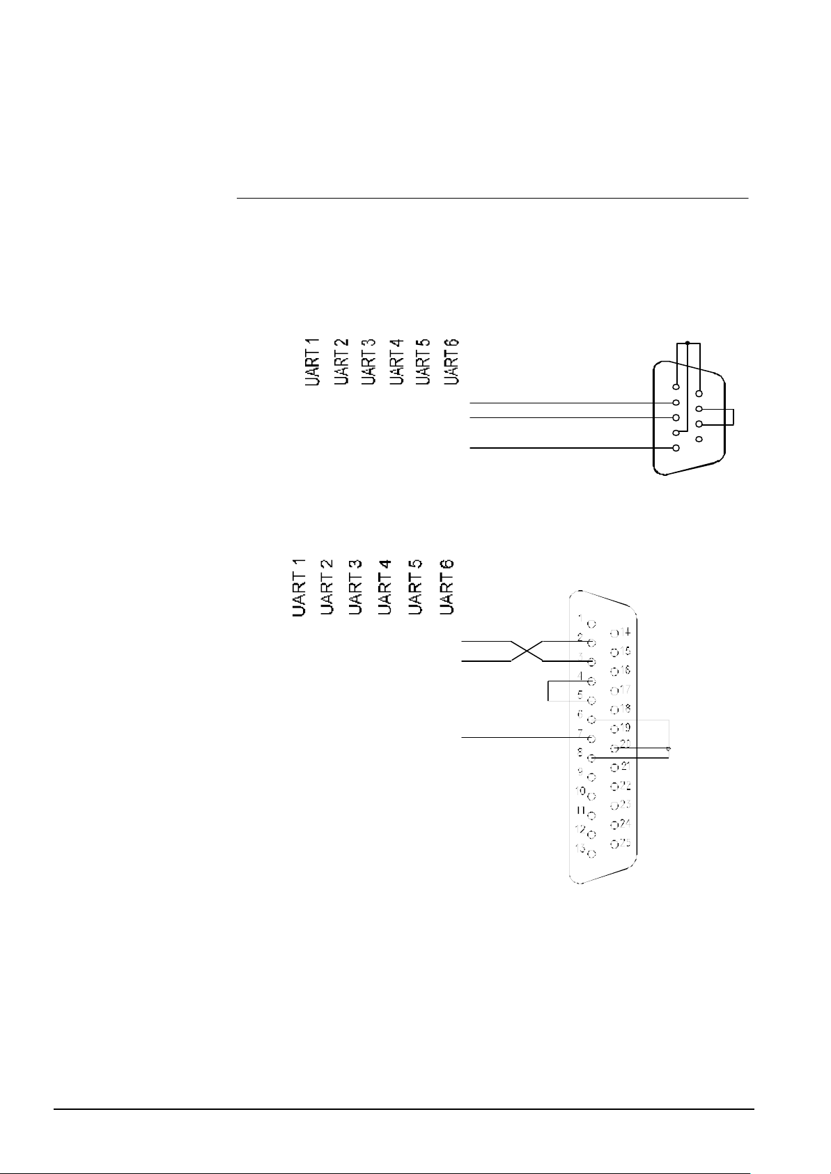
6.1 Connection to LMS
Fig. 10 and Fig. 11 show how to connect the GW-21 UARTs 1, 2, 3, 4, 5, 6 on the
screw terminal of the connection board to the LMS for a 9 pin connector and a 25 pin
connector respectively.
If there is only one LMS operating station, it can be connected to any UART among
those available. However, if there are two Operating Stations, they must be connected
to UARTs 1 and 2.
Female
TX
RX
GND
GW-21 LMS
Fig. 10 Connection to 9 pin D connector (screw terminal block)
Female connector
1 4 7 10 13 16
TX
2 5 8 11 14 17
RX
GND
3 6 9 12 15 18
1
2
3
4
5
6
7
8
9
16
Siemens Building Technologies
Cerberus Division
Fig. 11 Connection to 25 pin D connector (screw terminal block)
E1481b
06.2000
Page 21
6.2 Connection to GW-20
GW-21
Net-M Pad
Male connector
GND
This type of connection applies only to two level network configurations of the type
shown in Fig. 5 and Fig. 6.
Fig. 12 shows how to connect the GW-21 UARTs numbered 1, 2, 3, 4,5 and 6 on the
screw terminal block to the GW-20.
1
4
7
10
13
14
16
17
TX
RX
2
5
8
11
GND
Fig. 12 GW-21/GW-20 connection (screw terminal block)
All connections should be done using a shielded cable and D connectors with metallic
shells. Fasten the connector to the back plane of the gateway using the screws on the
connector shell.
3
6
9
12
15
18
6.3 Gateway to subsystem connection
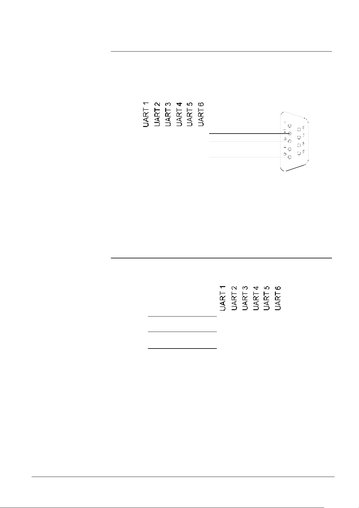
Each connector of the Subsystem Pad is used for one serial ports and to the connector
is linked only one subsystem of any type (Fig. 13).
To CSxx modem
terminal block
RX 2
1 4 10 13 16
7
TX
Siemens Building Technologies
Cerberus Division
TX 4
GND 3
Fig. 13 GW-21 to CSxx subsystem (screw terminal block)
2 5 8 11 14 17
3 6 9 12 15 18
RX
17
E1481b
06.2000
Page 22
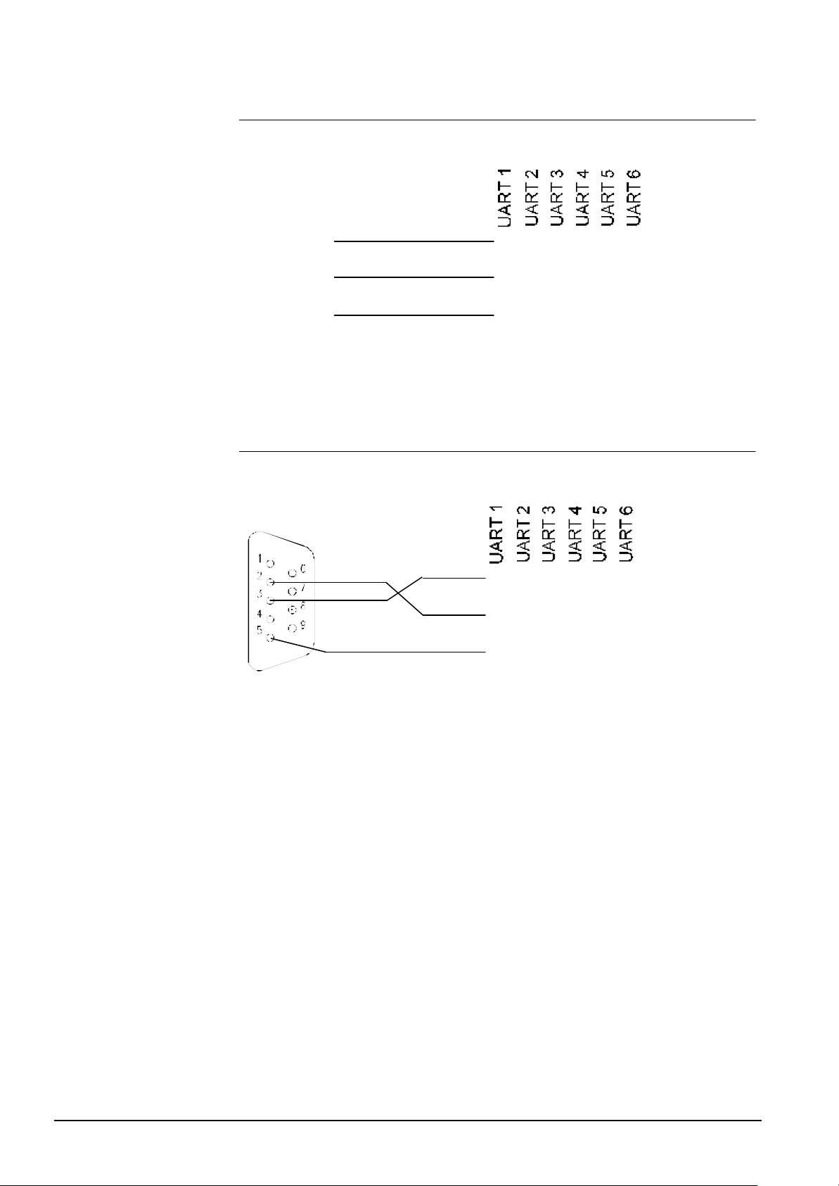
6.4 Gateway to CMX connection
GND
GND
Male Connector
The cable that links the gateway to the CMX IC-2 communication interface must be as
shown in Fig. 14.
To IC-2
RX 2
TX 3
GND 5
Fig. 14 GW-21 to CMX link (screw terminal block)
1 4 10 13 16
2 5 8 11 14 17
3 6 9 12 15 18
7
TX
RX
6.5 Gateway to Cerpass Connection/Interface
CC30-CK3003
The cable that links the gateway to the Cerpass communication interface must be as
shown in 0 .
Cerpass
CC30/CK3033
RX
TX
GND
1 4 10 13 16
2 5 8 11 14 17
3 6 9 12 15 18
7
TX
RX
18
Siemens Building Technologies
Cerberus Division
Fig. 15 GW-21 to CK3003
E1481b
06.2000
Page 23
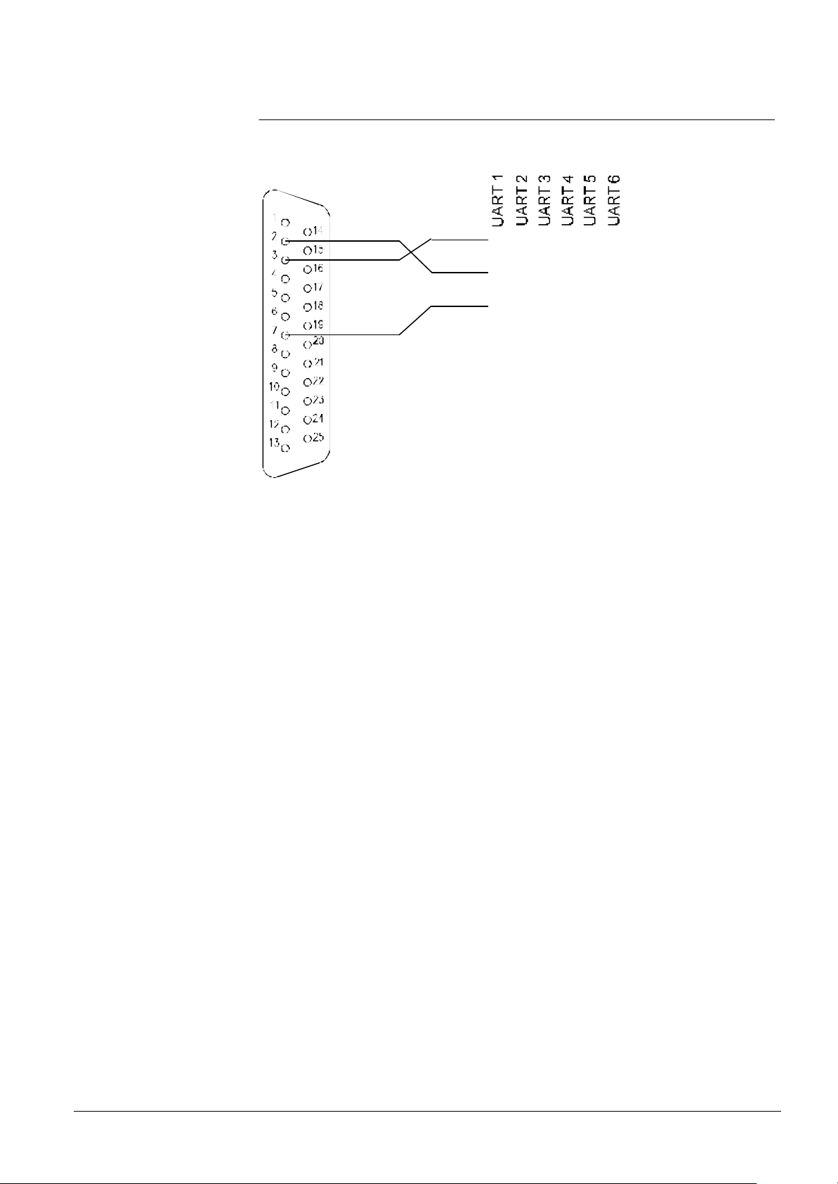
6.6 Gateway to Transliner
GND
Male Connector
The cable that links the gateway to the Transliner communication interface must be as
shown in fig. 6.7
Size
RX
1 4 10 13 16
7
TX
TX
GND
Fig. 16 GW-21 to Transliner
2 5 8 11 14 17
3 6 9 12 15 18
RX
Siemens Building Technologies
Cerberus Division
19
E1481b
06.2000
Page 24
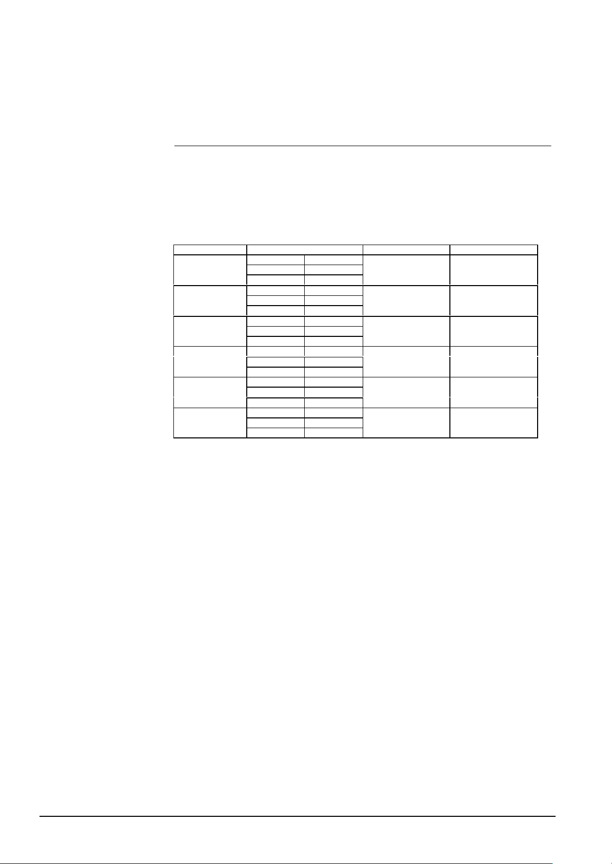
7 Three Configuration Examples
7.1 Example no. 1
In this first example we configure the gateway to connect to it 3 subsystems and 1
workstation, in this way:
§ 1 central station LMS UART 1
§ 3 subsystems CMX / CF9003 UART 2
§ CS4 UART 3
§ CCTV UART 4
The DIL-Switch settings are as follows:
DIL-Switch subsystem network address
UART 1
UART 2
UART 3
UART 4
UART 5
UART 6
Tab. 10
S1.4 ON
S1.5 ON
S1.6 ON
S2.2 ON
S2.3 ON
S2.4 OFF
S2.8 OFF
S3.1 ON
S3.2 OFF
S3.6 OFF
S3.7 OFF
S3.8 ON
S4.5 OFF
S4.6 OFF
S4.7 OFF
S5.3 OFF
S5.4 OFF
S5.5 OFF
LMS
CMX / CF9003 0
CS4 1
CCTV Burle 2
nothing (not installed)
nothing (not installed)
20
Siemens Building Technologies
Cerberus Division
E1481b
06.2000
Page 25
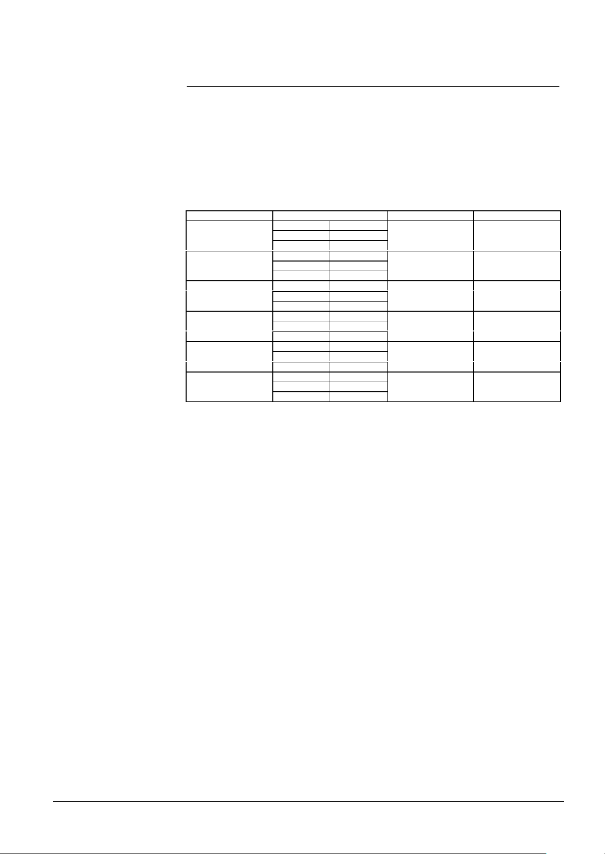
7.2 Example no. 2
In this second example, the gateway is configured for four subsystems and two monitoring stations:
§ first central station LMS (master) UART 1
§ second central station LMS (slave) UART 2
§ 4 subsystems CS11 UART 3
§ CS11 UART 4
§ CS4 UART 5
§ CS4 UART 6
Setting of DIL-Switches:
DIL-Switch subsystem network address
UART 1
UART 2
UART 3
UART 4
UART 5
UART 6
Tab. 11
S1.4 ON
S1.5 ON
S1.6 ON
S2.2 ON
S2.3 ON
S2.4 ON
S2.8 ON
S3.1 OFF
S3.2 OFF
S3.6 ON
S3.7 OFF
S3.8 OFF
S4.5 OFF
S4.6 ON
S4.7 OFF
S5.3 OFF
S5.4 ON
S5.5 OFF
LMS master
LMS slave
CS11 0
CS11 1
CS4 2
CS4 3
Remember that when your system needs two LMS stations, you must configure them
using UART 1 (as a master station) and UART 2 (as a slave station).
Siemens Building Technologies
Cerberus Division
21
E1481b
06.2000
Page 26
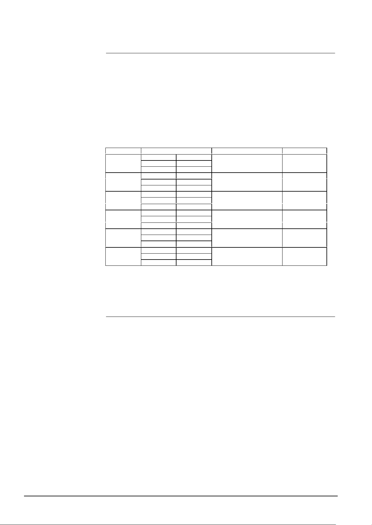
7.3 Example no. 3
In this third example we configure a two level network. The gateway is connected to
two GW-20s, one CS11, one standard subsystem and one CMX, in this way:
st
§ 1
GW-20 UART 1
§ 2nd GW-20 UART 2
§ No subsystems UART 3
§ Standard (CDDL / CDSF) UART 4
§ CMX / CF9003 UART 5
§ No subsystems UART 6
The two GW-20 communication speed is 9600 baud with ciphering not enabled.
The DIL-Switch settings are as follows:
DIL-Switch subsystem network address
UART 1
UART 2
UART 3
UART 4
UART 5
UART 6
Tab. 12
S1.4 ON
S1.5 ON
S1.6 ON
S2.2 ON
S2.3 ON
S2.4 ON
S2.8 ON
S3.1 OFF
S3.2 OFF
S3.6 OFF
S3.7 ON
S3.8 ON
S4.5 ON
S4.6 ON
S4.7 OFF
S5.3 OFF
S5.4 OFF
S5.5 OFF
1st GW-20 (two level network)
2nd GW-20 (two level network)
CS11 0
Standard (CDDL / CDSF) 1
CMX / CF9003 2
No subsystems 3
8 Troubleshooting
On problems with the communication to the control units:
§ First check if the baud rates and the subsystem’s protocols of the gateway are set up
correctly (see Sections 4.2.1 and 5 of this manual).
§ Check if the connections of the gateway to the monitoring system (PC or GW-20) and
to the control unit have been implemented in the way described in Sections 6.1 and
6.2 of this manual.
If the red LED on the CPU board blinks fast (4 Hz):
§ there could be a configuration error - check carefully the configuration you set.
or
§ there is a download in progress. Wait till the download ends
If the red LED on the CPU board blinks slow (1 Hz):
§ the RAM is fault - call for technical assistance
If the green LED on the CPU board does not blink
(it either permanently ON or OFF)
§ there is a general failure - call for technical assistance
22
Siemens Building Technologies
Cerberus Division
E1481b
06.2000
Page 27
9 Appendix A: STT/GW-21 Connection
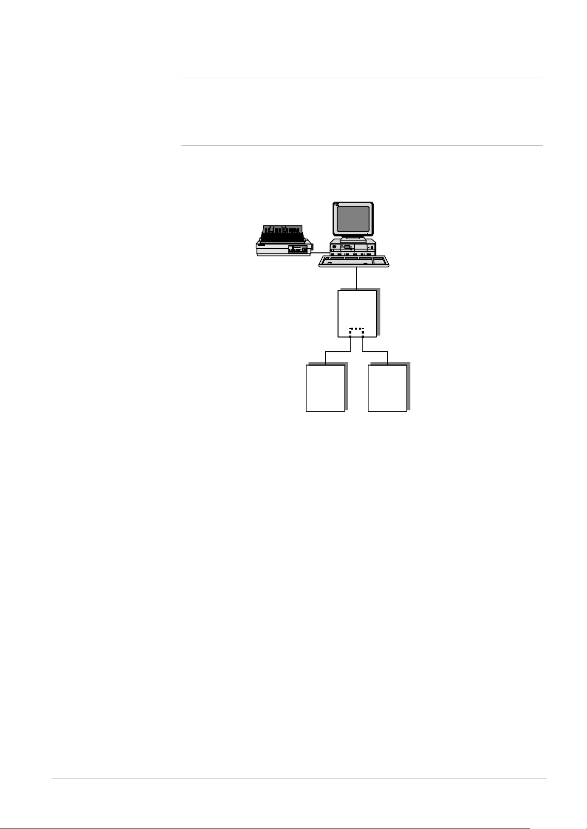
The STT is a device manufactured and sold by Cerberus Guinard. It can be connected
to the Gateway GW-21 in two different ways, shown in Fig. 17 and Fig. 18.
9.1 First case
Using this configuration the LMS system does not see the STT subsystem: its role is
purely local. The communication line that connects GW-21 to STT works only from the
GW-21 to the STT. Up to 3 CS11 can be connected to the gateway and all three of
them can use the STT.
GW-21.xx
CS11 STT
Fig. 17 STT as synoptic panel driver
STT has to be configured as STT subsystem on the gateway and it must not be confi gured on LMS. STT used as synoptic panel can be connected to any available UARTs.
Siemens Building Technologies
Cerberus Division
23
E1481b
06.2000
Page 28
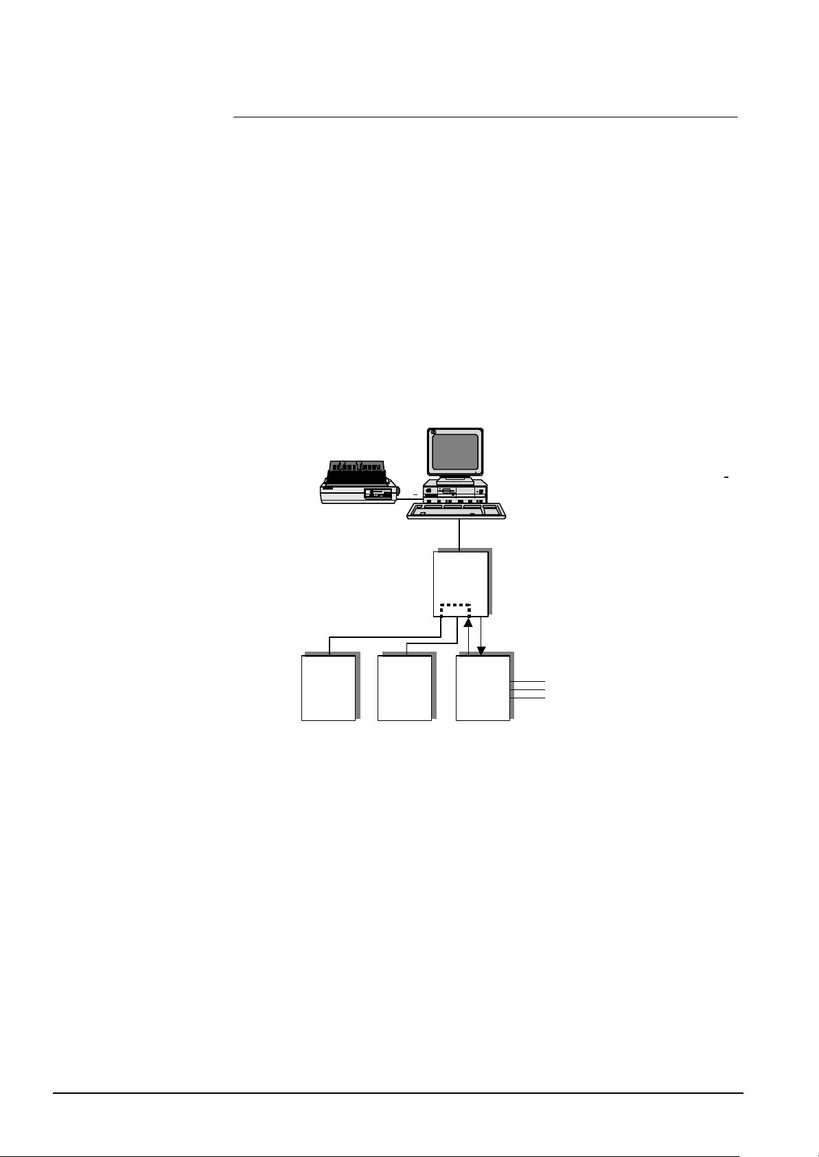
9.2 Second case
In this configuration, the LMS system sees the STT as a subsystem and it fully manages it. Two lines are needed to connect the STT to the gateway.
The first line is a slave line for the gateway (and a master line for the STT), has to be
configured as a CS11 subsystem on the gateway (see Section 4 for the proper setting)
but it must be configured as STT subsystem on LMS.
The second line is a master line for the gateway (and a slave line for the STT), has to
be configured as STT subsystem on the gateway (see Section 4 for the proper setting)
and it must not be configured on LMS.
This configuration allows to connect a maximum of two CS11 to the Gateway; both of
them can use the STT.
The address used for the first line (configured as STT on LMS) must be adjacent and
lower than the address used for the second line (that is not configured on LMS). The
two lines must be logically contiguous but not necessarily physically contiguous; i.e. if
there is one LMS that use UARTs 2, the first line can be on UART 1 and the second
line can be on UART 3. In this case they are not physically contiguous but are logically
contiguous (see examples below).
Fig. 18 STT as a subsystem
GW-21.xx
STTCS11 CS11
24
Siemens Building Technologies
Cerberus Division
E1481b
06.2000
Page 29
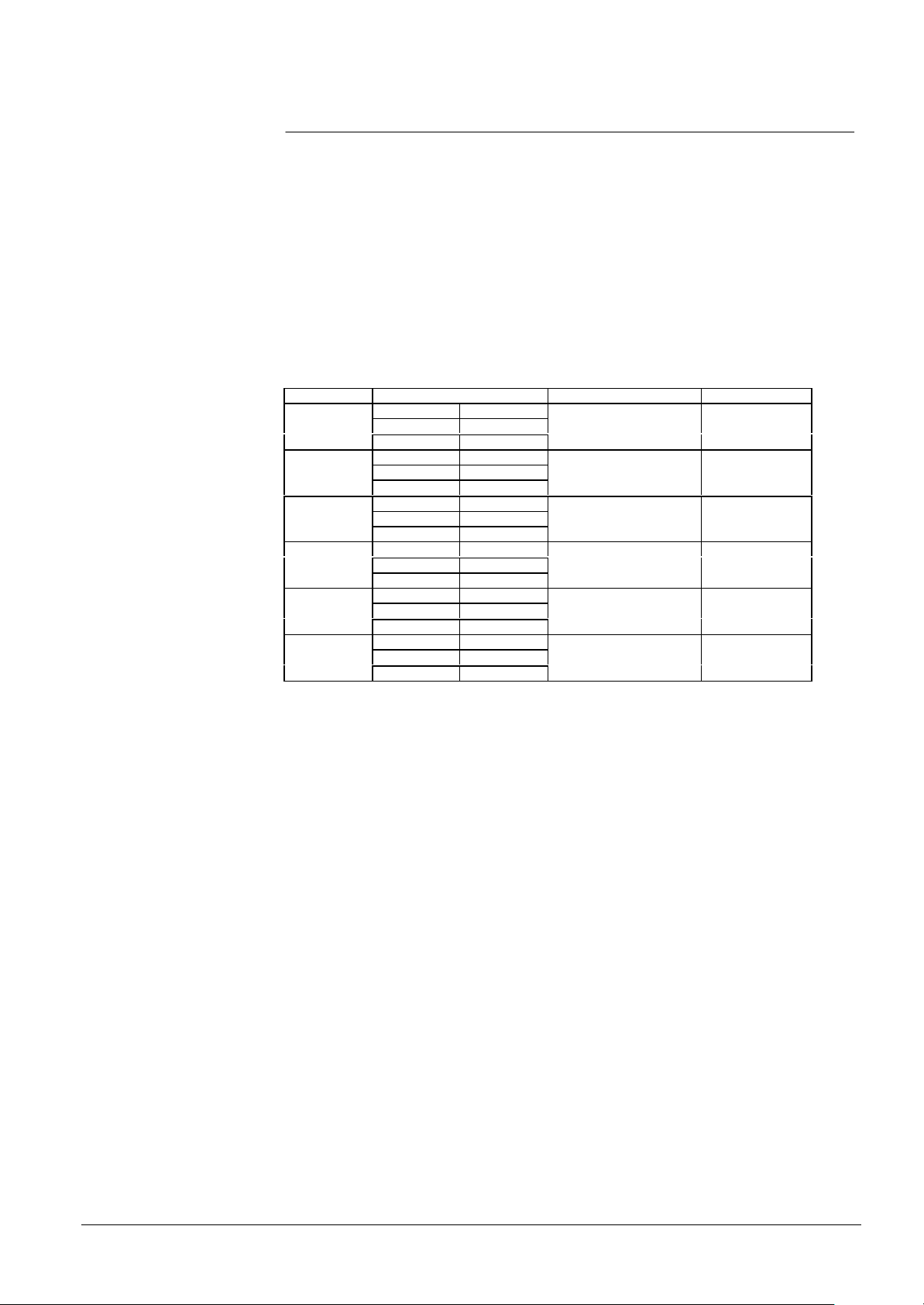
9.3 Example no. 1
In this first example we configure the gateway to connect to it one STT with master and
slave lines, two LMS, one standard subsystem and one CMX, in this way:
st
§ 1
central station LMS UART 1
§ 2nd central station LMS UART 2
§ STT first line UART 3
§ STT second line UART 4
§ Standard UART 5
§ CMX / CF9003 UART 6
Please note that in this example the two lines are not physically contiguous (they are on
UART 1 and 4) but they are logically contiguous (the network addresses are 0 and 1)
The DIL-Switch settings are as follows:
DIL-Switch subsystem network address
UART 1
UART 2
UART 3
UART 4
UART 5
UART 6
Tab. 13
S1-4 ON
S1-5 ON
S1-6 ON
S2-2 ON
S2-3 ON
S2-4 ON
S2-8 ON
S3-1 OFF
S3-2 OFF
S3-6 ON
S3-7 OFF
S3-8 ON
S4-5 OFF
S4-6 ON
S4-7 ON
S5-3 ON
S5-4 ON
S5-5 OFF
LMS
LMS
STT first line (=CS11) 0
STT second line (=STT) 1
Standard 2
CMX / CF9003 3
Siemens Building Technologies
Cerberus Division
25
E1481b
06.2000
Page 30
9.4 Example no. 2
In this second example we configure the gateway to connect to it one STT with master
and slave lines, one CS4 and one LMS, in this way:
§ central station LMS UART 1
§ CS4 UART 2
§ STT first line UART 3
§ STT second line UART 4
§ no subsystems UART 5
§ no subsystems UART 6
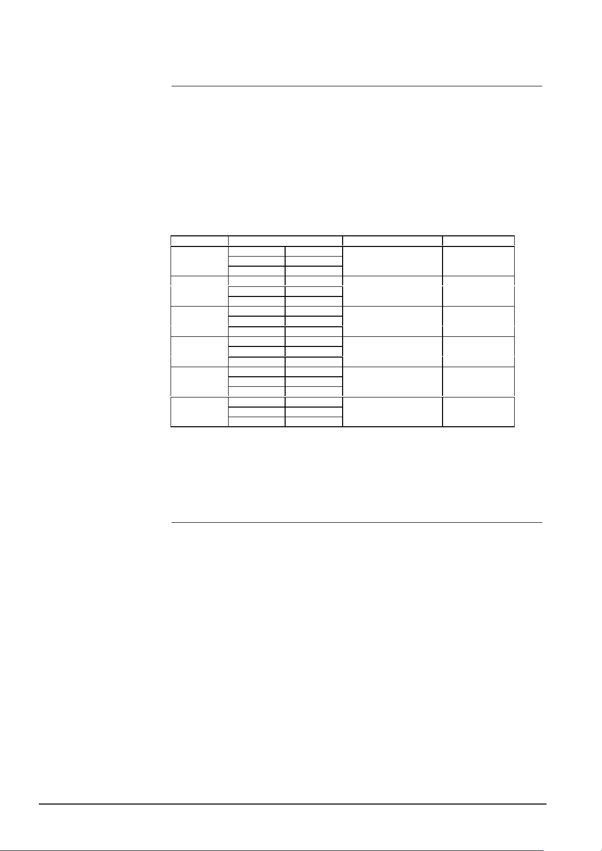
In this example the two STT lines are contiguous both logically and physically.
The DIL-Switch settings are as follows:
DIL-Switch subsystem network address
UART 1
UART 2
UART 3
UART 4
UART 5
UART 6
Tab. 14
S1-4 ON
S1-5 ON
S1-6 ON
S2-2 OFF
S2-3 ON
S2-4 OFF
S2-8 ON
S3-1 OFF
S3-2 OFF
S3-6 ON
S3-7 OFF
S3-8 ON
S4-5 OFF
S4-6 OFF
S4-7 OFF
S5-3 OFF
S5-4 OFF
S5-5 OFF
LMS
CS4
STT first line (=CS11) 1
STT second line (=STT) 2
no subsystems
no subsystems
10 Appendix B: Firmware Version
Please refer to latest edition of LMS News concerning GW-21 firmware release. Contact Cerberus Dati Customer Support
Tel. +39-02-452819.1
Fax +39-02-452819.33
e-mail [email protected]
Internet www.cdi.cerberus.ch
26
Siemens Building Technologies
Cerberus Division
E1481b
06.2000
Page 31
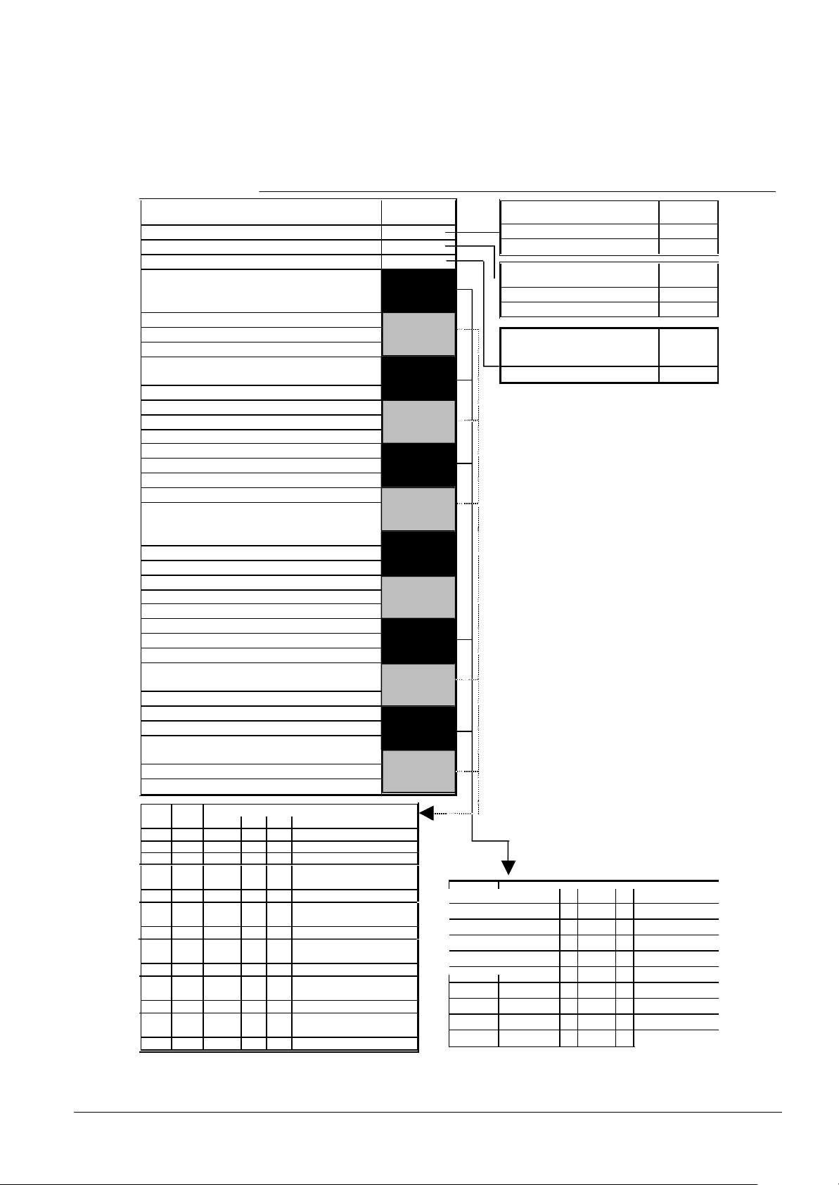
11 Appendix C:
S5.8
DIL-Switches Descri ption
JUMPER FUNCTION VALUE
S1.1 Configuration
S1.2 Cerban vitality
S1.3 Ciphering (only on two level network)
S1.4 subsystem type UART 1
S1.5 subsystem type UART 1
S1.6 subsystem type UART 1
S1.7 baud rate UART 1
S1.8 baud rate UART 1
S2.1 baud rate UART 1
S2.2 subsystem type UART 2
S2.3 subsystem type UART 2
S2.4 subsystem type UART 2
S2.5 baud rate UART 2
S2.6 baud rate UART 2
S2.7 baud rate UART 2
S2.8 subsystem type UART 3
S3.1 subsystem type UART 3
S3.2 subsystem type UART 3
S3.3 baud rate UART 3
S3.4 baud rate UART 3
S3.5 baud rate UART 3
S3.6 subsystem type UART 4
S3.7 subsystem type UART 4
S3.8 subsystem type UART 4
S4.2 baud rate UART 4
S4.3 baud rate UART 4
S4.4 baud rate UART 4
S4.5 subsystem type UART 5
S4.6 subsystem type UART 5
S4.7 subsystem type UART 5
S4.8 baud rate UART 5
S5.1 baud rate UART 5
S5.2 baud rate UART 5
S5.3 subsystem type UART6
S5.4 subsystem type UART6
S5.5 subsystem type UART6
S5.6 baud rate UART 6
S5.7 baud rate UART 6
S5.8 baud rate UART 6
UART Spare 9600 4800 2400 1200 600 300 150
BAUD RATE
1 S1.7 ON OFF ON OFF ON OFF ON OFF
S1.8 ON ON OFF OFF ON ON OFF OFF
ON ON ON ON OFF OFF OFF OFF
S2.1
2 S2.5 ON OFF ON OFF ON OFF ON OFF
S2.6 ON ON OFF OFF ON ON OFF OFF
S2.7 ON ON ON ON OFF OFF OFF OFF
3 S3.3 ON OFF ON OFF ON OFF ON OFF
S3.4 ON ON OFF OFF ON ON OFF OFF
S3.5 ON ON ON ON OFF OFF OFF OFF
4 S4.2 ON OFF ON OFF ON OFF ON OFF
S4.3 ON ON OFF OFF ON ON OFF OFF
S4.4 ON ON ON ON OFF OFF OFF OFF
5 S4.8 ON OFF ON OFF ON OFF ON OFF
S5.1 ON ON OFF OFF ON ON OFF OFF
S5.2 ON ON ON ON OFF OFF OFF OFF
6 S5.6 ON OFF ON OFF ON OFF ON OFF
S5.7 ON ON OFF OFF ON ON OFF OFF
ON ON ON ON OFF OFF OFF OFF
Configuration by Flash EPROM
Configuration by dip-switches
Vitality message filtered
Vitality message not filtered
Ciphering enabled ON
Ciphering disabled OFF
UART JUMPER cz10/cs11
Dip switches
cs4/cz12 CMX/ CCTV Burle
1 S1.4 ON OFF ON OFF ON OFF ON
2 S2.2 ON OFF ON OFF ON OFF ON
3 S2.8 ON OFF ON OFF ON OFF ON
4 S3.6 ON OFF ON OFF ON OFF ON
5 S4.5 ON OFF ON OFF ON OFF ON
6 S5.3 ON OFF ON OFF ON OFF ON
/cc60
S1.5 OFF ON ON OFF OFF ON ON
S1.6 OFF OFF OFF ON ON ON ON
S2.3 OFF ON ON OFF OFF ON ON
S2.4 OFF OFF OFF ON ON ON ON
S3.1 OFF ON ON OFF OFF ON ON
S3.2 OFF OFF OFF ON ON ON ON
S3.7 OFF ON ON OFF OFF ON ON
S3.8 OFF OFF OFF ON ON ON ON
S4.6 OFF ON ON OFF OFF ON ON
S4.7 OFF OFF OFF ON ON ON ON
S5.4 OFF ON ON OFF OFF ON ON
S5.5 OFF OFF OFF ON ON ON ON
Cf9003
o Cerloop
STT SEEP/CDDL/
Cerpass/Size
LMS, two level
S1.1
OFF
ON
S1.2
OFF
ON
S1.3
network
Siemens Building Technologies
Cerberus Division
Fig. 19
27
E1481b
06.2000
Page 32

12 Appendix D: GW-21 Rev. A
12.1 The connection board
The connection board has two connectors to insert the CPU and I/O board in.
On the board there are two DB9 D connectors for the two serial ports (UARTs 1 and 2).
UART 2 is a full modem port, i.e. all the standard modem signals for a DB9 connector
are foreseen. UART 1 lacks RI (Ring Indicator) and DCD (Data Carrier Detector) signals.
UARTs 3 and 4 are accessible through screw connectors located on the right side of
the connection board. Only the TX, RX and GND signals are available.
UARTs 5 and 6, if the expansion board is installed, are accessible through the screw
connectors from 31 to 36 on the connector block on the left side of the connection
board.
On the same connection board there are the two power supply blocks. Each block has
three pins: the central one is the ground, the two laterals are marked + and -. You must
connect here the voltage source (10 to 30 V d.c.).
28
Siemens Building Technologies
Cerberus Division
E1481b
06.2000
Page 33
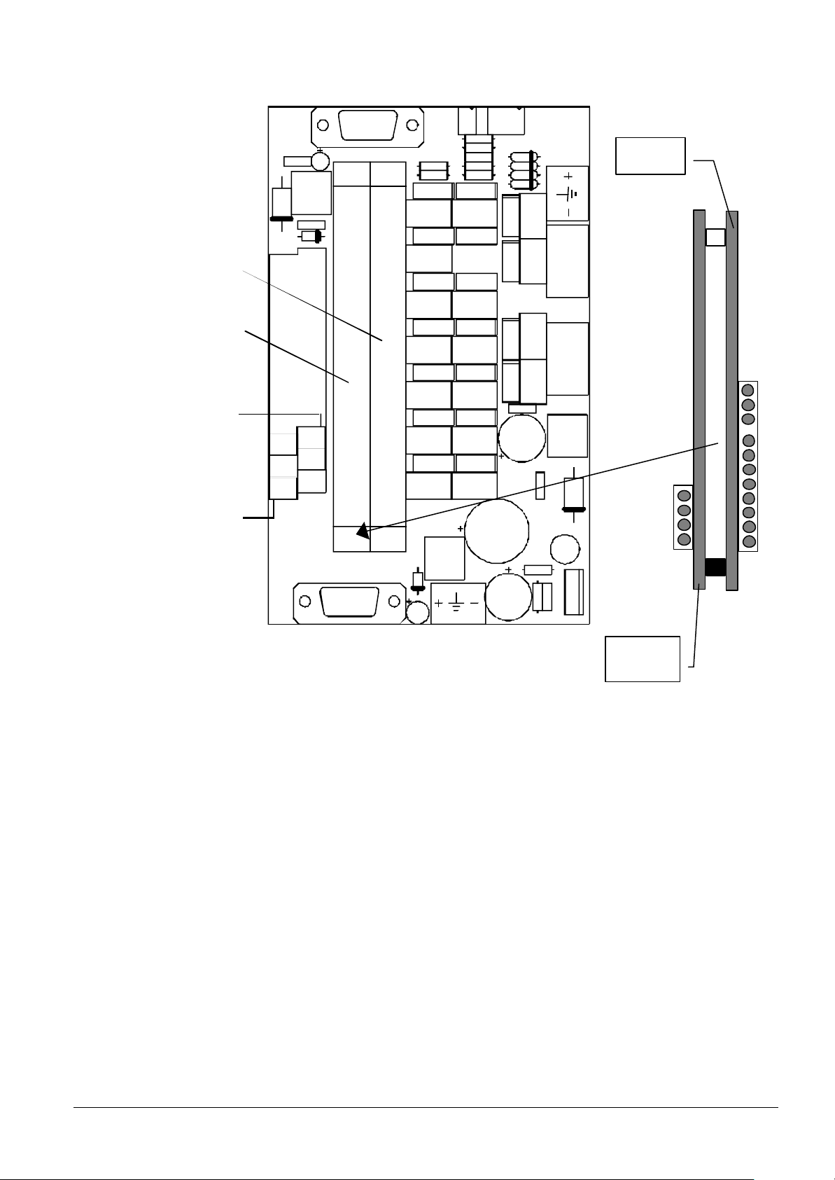
(Full modem)
(13.8 V)
(modem without RI
CPU board
I/O expansion
board
DB1
UART1
and DCD)
CN3
LON
CN4
CPU board
I/O expansion
board
U ART 6
U ART 5
32
TX
R X
GND
36
31
TX
R X
GND
35
CN2
TX
GND
GND
RX
CN5
CN6
TX
GND
GND
RX
CD95800
1
2
U ART3
3
4
1
2
U ART4
3
4
DB2
UA RT2
Fig. 20 The connection board
CN1
Power
CD95802
Siemens Building Technologies
Cerberus Division
29
E1481b
06.2000
Page 34
12.2 Inside the CS4
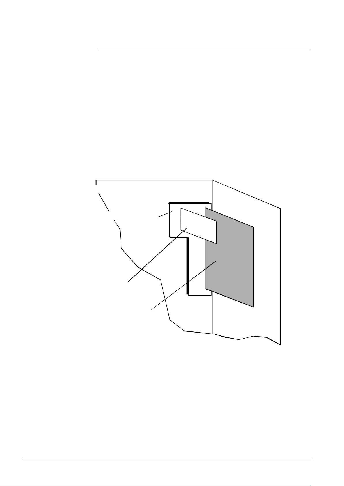
In the CS4 intrusion detection control unit the gateway can be mounted on the Lshaped plate on the right side of some of the standard housings.
To properly mount the Gateway GW-21, you must follow the procedure described below:
4. remove the K3H010 board;
5. remove the L-shaped plate from the chassis;
6. unscrew the four plastic guided used to host the K1D080 and K1H021 boards for
Cerloop;
7. mount the four spacers provided with GW-21 on the L-shaped plate;
8. mount the L-shaped plate inside the chassis;
9. mount the connection board of the GW-21;
10. mount the CPU board and the expansion board, if needed, on the connection
board
11. mount again in its place the K3H010 board
12. Please follow this sequence, because the screws used to mount the L-shaped
plate inside the chassis are under the connection board.
CS4 standard housing
L-shaped plate
GW-21
K3H010
Fig. 21 Slots in the CS4 control unit
30
Siemens Building Technologies
Cerberus Division
E1481b
06.2000
Page 35
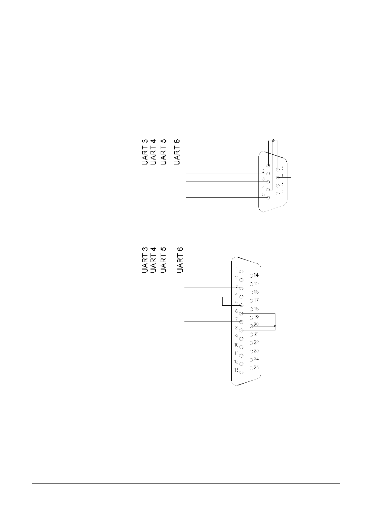
12.3 Connection to LMS
GW-21
LMS (PC)
Fig. 22 and Fig. 23 show how to connect the GW-21 UARTs 3,4, 5, 6 on the screw terminal of the connection board to the LMS for a 9 pin connector and a 25 pin connector
respectively.
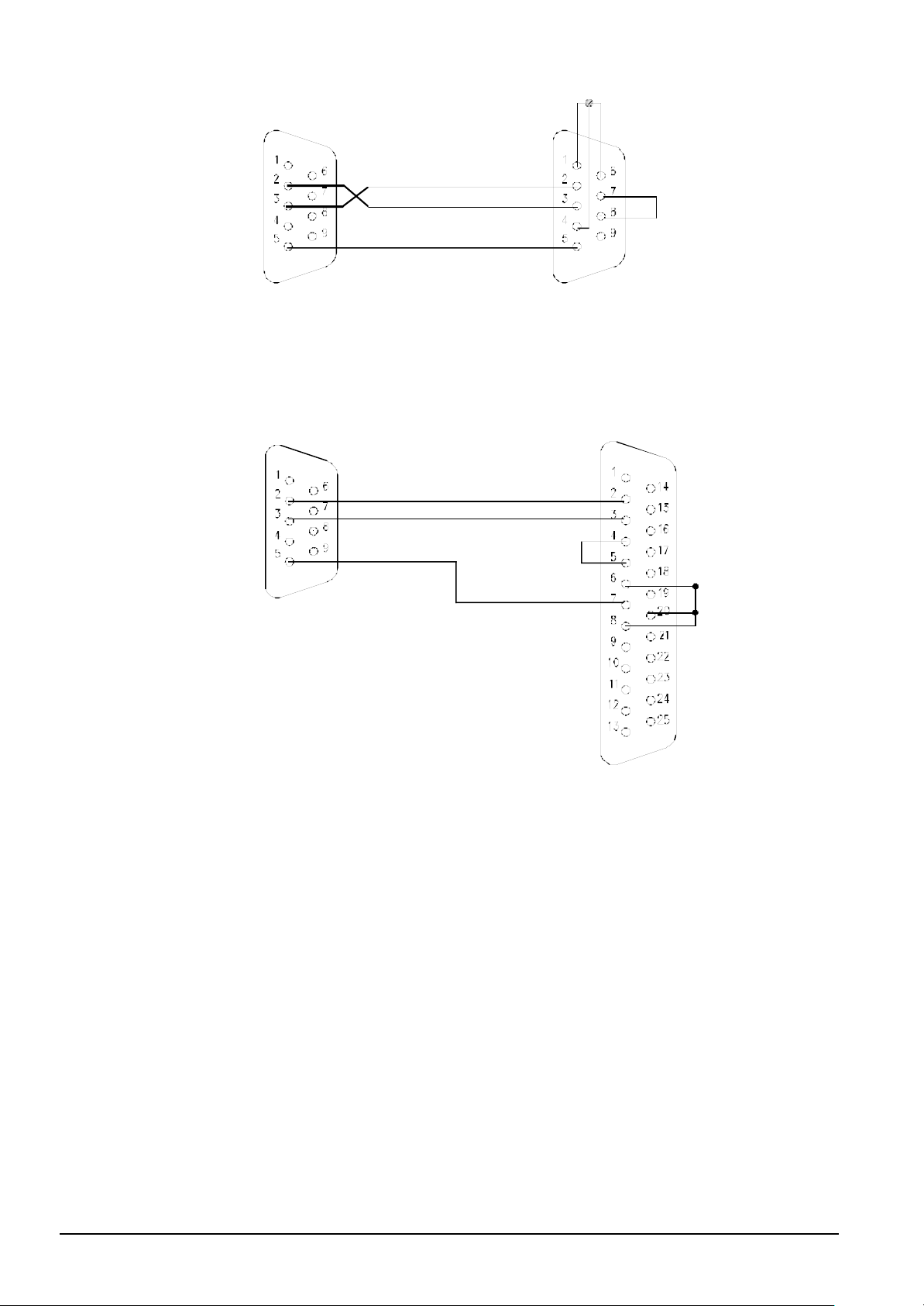
Fig. 24 and Fig. 25 show how to connect the GW-21 UARTs 1 and 2 on the two DB9
connectors of the connection board to the LMS for a 9 pin connector and a 25 pin connector re spectively.
If there is only one LMS operating station, it can be connected to any UART among
those available. However, if there are two Operating Stations, they must be connected
to UARTs 1 and 2.
Female connector
TX
RX
GND
Fig. 22 Connection to 9 pin D connector (screw terminal block)
1 1 32 3 1
4 4 34 33
2 2 36 35
G W-21 LMS (PC)
Female connector
RX 4 4 34 33
TX
GND
1 1 32 31
2 2 36 35
Siemens Building Technologies
Cerberus Division
Fig. 23 Connection to 25 pin D connector (screw terminal block)
31
E1481b
06.2000
Page 36
GW-21
LMS (PC)
Male connector Female connector
GW-21
LMS (PC)
UARTs 1 and 2
Fig. 24 Connection to 9 pin D connector (DB9 connectors)
Male connector Female connector
UARTs 1 and 2
32
Siemens Building Technologies
Cerberus Division
Fig. 25 Connection to 25 pin D connector (DB9 connectors)
E1481b
06.2000
Page 37
12.4 Connection to GW-20
GW-21
Net-M Pad
Male connector
GW-21
Net-M Pad
This type of connection applies only to two level network configurations of the type
shown in Fig. 5 and Fig. 6.
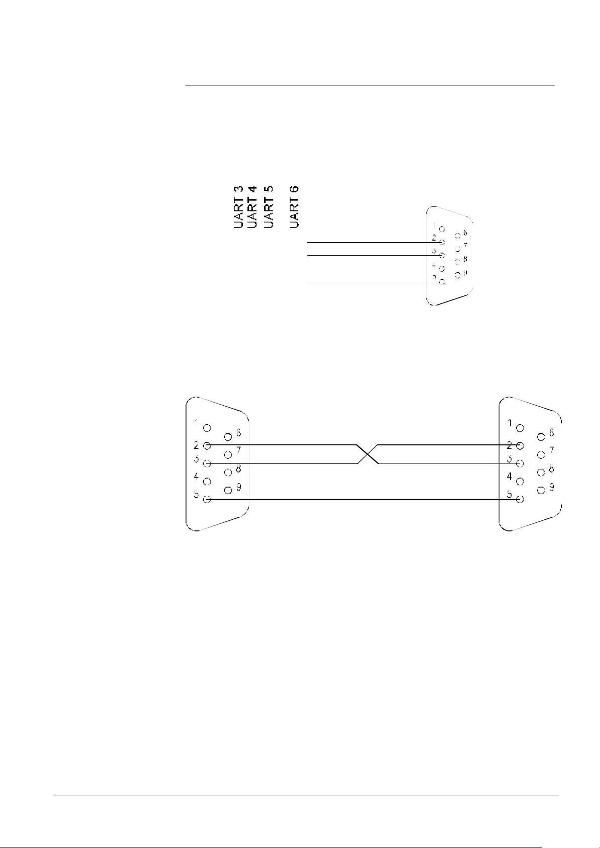
Fig. 26 shows how to connect the GW-21 UARTs numbered 3,4,5 and 6 on the screw
terminal block to the GW-20.
Fig. 26 shows how to connect the GW-21 UARTs 1 and 2 on the two DB9 connectors
of the connection board to the GW-20.
TX
RX
GND
Fig. 26 GW-21/GW-20 connection (screw terminal block)
1 1 32 31
4 4 34 33
2 2 36 35
Male connector Male connector
UARTs 1 and 2
Siemens Building Technologies
Cerberus Division
Fig. 27 GW-21/GW-20 connection (DB9 connectors)
All connections should be done using a shielded cable and D connectors with metallic
shells. Fasten the connector to the back plane of the gateway using the screws on the
connector shell.
33
E1481b
06.2000
Page 38
12.5 Gateway to subsystem connection
GW-21
GND
2 2 36 35
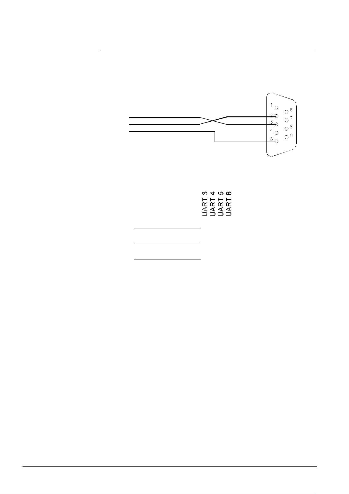
Each connector of the Subsystem Pad is used for one serial ports and to the connector
is linked only one subsystem of any type (Fig. 28 and Fig. 29).
Male connector
To CSxx modem
terminal block
2 - RX
4 - TX
3 - SIGNAL
GROUND
Fig. 28 GW-21 to CSxx subsystem (UARTs 1 and 2)
UARTs 1 and 2
To CSxx modem
terminal block
RX 2
TX 4
GND 3
Fig. 29 GW-21 to CSxx subsystem (screw terminal block)
TX1 1 32 31
RX4 4 34 33
34
Siemens Building Technologies
Cerberus Division
E1481b
06.2000
Page 39
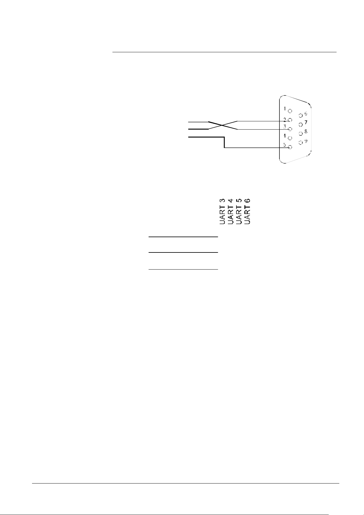
12.6 Gateway to CMX / CF9003 connection
GW-21
GND
2 2 36 35
The cable that links the gateway to the CMX IC-2 communication interface must be as
shown in Fig. 30 and Fig. 31.
Male co nnector
To IC-2
To terminal no. 3 RS 232 RX
To terminal no. 4 RS 232 TX
To terminal no. 5 RS 232 GND
Fig. 30 GW-21 to CMX link (UARTs 1 and 2)
UARTs 1 and 2
To IC-2
RX 2
TX 3
GND 5
Fig. 31 GW-21 to CMX link (screw terminal block)
TX1 1 32 31
RX4 4 34 33
Siemens Building Technologies
Cerberus Division
35
E1481b
06.2000
Page 40

13 Appendix E: Safety Instructions
Scope of document (See EN 60950 Sec. 1.7.2)
The safety instructions contained in this document are intended for use by service/maintenance personal for the proper installation of the equipment.
Wire size and isolation (See EN 60950 Sec. 1.5.5; 3.1.1; 3.2.4)
When connecting to the mains supply the following prescriptions must be observed.
The connection on the equipment side must done using an approved (IEC 320-1/C13)
type P-587 connector.
Isolation:
The cable (wires) used must be suitable for 230 volts with a test voltage 1500V.
Wire size:
The wires in must have a cross section adequate for the current rating of the protection
devices of the in house mains circuit according to the following table:
Up to 6A minimum 0.75 mm ²
6A to 10A 1.0 mm²
Mains supply tolerance (See EN 60950 Sec. 1.6.5)
The mains supply tolerance of this equipment is ±10%.
Mains voltage adjustment (See EN 60950 Sec. 1.7.4; 4.3.1)
This equipment has no mains voltage adjustment. The input voltage range permits operation from 100 to 240 VAC.
Protection in building installation (See EN 60950 Sec. 1.7.11)
In house wiring to the socket to which the unit will be connected must be in accordance
with local building codes and must include a valid protective earth. It must also be fused
at max. 10A as this is the maximum current rating of the power inlet.
Fuses (See EN 60950 Sec. 1.7.6)
The equipment is protected by a fuse located in the power inlet socket. The fuse is rating is 3.15A/T (Time delay)
Wire fixing (See EN 60950 Sec. 3.3.4)
Mains wires must be fixed as close as possible to the terminal in such a way that if it
becomes loose it will not touch any ungrounded part. This fixing must be done by the
installer.
36
Siemens Building Technologies
Cerberus Division
Internal wiring (See EN 60950 Sec. 3.1.2; 3.1.3)
Mains wires must be routed in such a way to avoid the following:
contact with sharp edges that could damage insulation.
excessive strain on wire and terminal connections
loosening of terminal connections
E1481b
06.2000
Page 41

Siemens Building Technologies
Cerberus Division
37
E1481b
06.2000
Page 42

Page 43

Keyword index
B
Baud rate 25
GW-21 1, 2, 3, 7, 8, 9, 10, 12, 13, 14, 16, 17, 19, 20,
21, 22, 26, 29, 32, 33, 34, 36, 37, 38
GW-21.04 1, 7
GW-21.06 1, 7
C
Cable 21, 22, 36, 38
CC60 14
CCTV 23, 25, 28, 29
CCTV Burle 14
CDDL 14
CDSF 14
Cerban 9
Cerban vitality 16
Cerloop 14
CF9003 I, 2, 12, 14, 18, 23, 25, 28, 29, 38
Ciphering 16
CMSDL 9
CMX 14, 21, 23, 25, 28, 38
Connection board 5, 7, 32, 34, 36
connectors 36
CPU board 1, 3, 4, 7, 12, 14, 25, 26
CS11 14, 24, 26, 27
CS4 10, 11, 14, 23, 24, 33
CZ10 14
CZ12 14
L
LED 25, 26
Line splitter 9
LMS 1, 2, 7, 14, 15, 23, 24, 26, 27, 28, 29, 34
M
Master station 24
Message traffic 16
N
Net-M Pad 9
P
PC 25
Protocol converter 9
PROTOCOL SUPPORT 29
R
D
Dip-switch 16, 23, 24, 25, 28, 29
E
EPROM 12
Example 23, 24, 25, 28, 29
Expansion board 4, 7
F
FIRMWARE 29
Flash EPROM 12, 16
G
GW-20 I, 2, 8, 9, 16, 17, 20, 25, 36
Redundant configuration 16
S
SEEP 14
Slave station 24
STT 2, 14, 25, 26, 27, 28
Subsystem Pad 37
Subsystem setting 14
T
Traffic 16
Troubleshooting 25
Two level network 14
W
Workstation 1, 14, 23
Siemens Building Technologies
Cerberus Division
1
06.2000
Page 44

Siemens Building Technologies AG
Cerberus Division
CH-8708 Männedorf
Alte Landstrasse 411
Tel. +41 1 - 922 61 11
Fax +41 1 - 922 64 50
www.cerberus.ch
Cerberus
Security
for People
and Assets
Cerberus Division
Replaces e1481a
Doc.no e1481bSiemens Building Technologies
Edition: 06.2000
 Loading...