

Page 1
instabus EIB
Technical Product Information
September 2001
Binary Input N 260 5WG1 260-1AB01
4 x 230 V AC
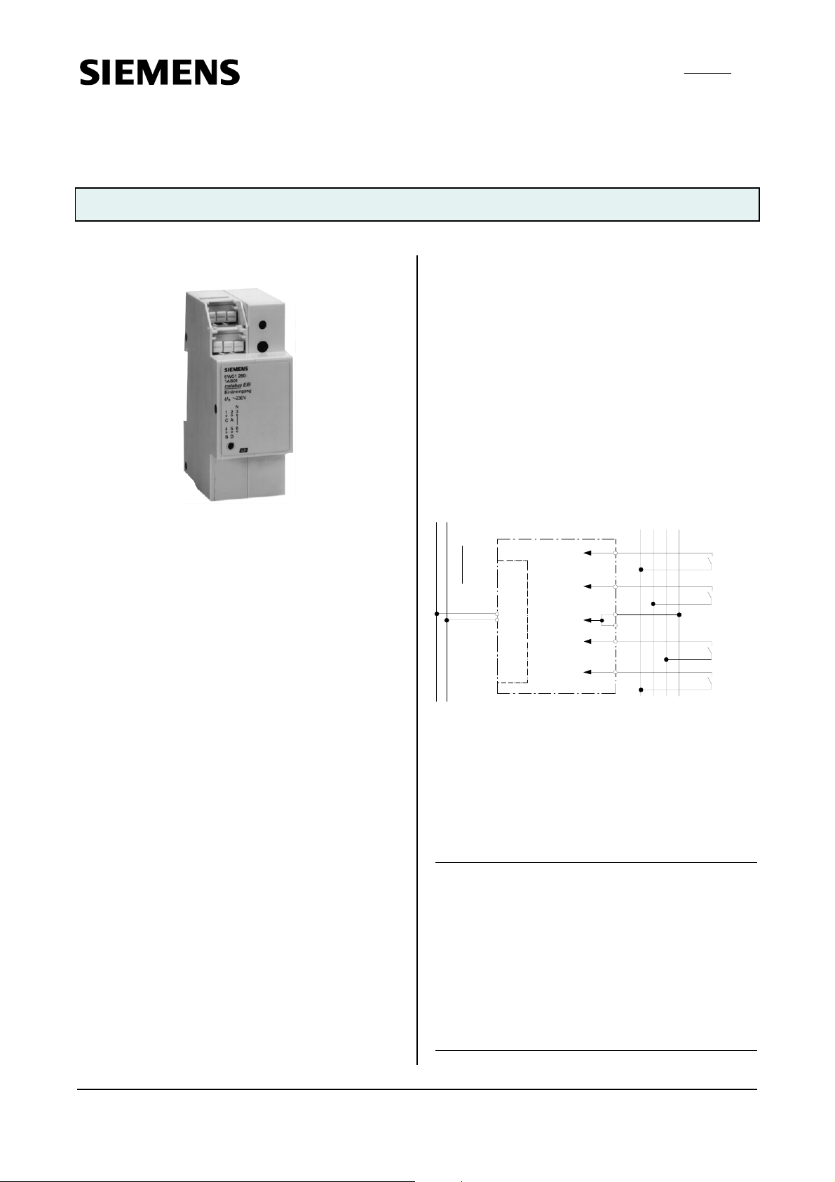
Product and Applications Description
The binary input N 260 is a N-system DIN-rail mounted
device with four inputs for AC 230 V switching or keying
signals from separate external outside lines (L1, L2, L3)
with a shared reference potential (N).
Each of the inputs can be assigned various tasks
depending on the application program used, i.e. the
binary input N 260 consists of the device (hardware) and
its application programs (software).
Appropriate application programs are available for
the different tasks the binary input N 260 can handle;
e.g. sending of on/off telegrams at different edges of the
input signal either event-controlled or cyclic with
parametrisable repetition intervals.
With the ETS (EIB Tool Software) the application
program is selected, its parameters and addresses are
assigned appropriately, and downloaded to the binary
input N 260.
Applikationsprogramme
12 S4 BinCycl 240505
• 4 binary inputs
• each input allows switching on/off or toggling at
leading or trailing edge
• allows cyclic sending
• allows sending at bus voltage recurrence
• sending condition can be set
12 S2 On-off-toggle/Dim/Shu 220703
• 4 binary inputs
• allows configuration for dimmer/shutter or
on/off/sending value
• switching at leading edge or at leading and trailing
edge
• switching short/long key depression
• sending value at leading edge or at leading and
trailing edge
• duration of long key depression can be set
• used type of contacts can be set
11 S4 BinVal 240A01
• 4 binary inputs
• each input allows to send values at leading edge
and/or at leading and trailing edge
• allows cyclic sending
• allows delay
• allows interlocking
Example of Operation
load circuit
AC 230/400V
L1
binary input N 260
instabus EIB
channel A
channel B
N
channel C
bus coupling unit
channel D
L2 L3 N
2
4
3
6
1
5
switch ing /
keying sign als
Installation Instructions
• The device may be used for permanent interior
installations in dry locations within distribution boards.
WARNING
V
• The device may be built into distribution boards
(230/400 V) if VDE-certified devices are used
exclusively and must be mounted and commissioned
by an authorised electrician.
• A safety disconnection of the device must be possible.
Especially if the device is connected to different
phases.
• Free DIN rail areas must be covered with covers,
order no. 5WG1 192-8AA01.
• The prevailing safety rules must be heeded.
• The device must not be opened. A device suspected
faulty should be returned to the local Siemens office.
Siemens AG N 260, 4 pages Technical Manual
Automation and Drives Group
Electrical Installation Technology Siemens AG 2001 Update: http://www.siemens.de/installationstechnik
P.O.Box 10 09 53, D-93009 Regensburg Subject to change without prior notice
2.7.1.3/1
Page 2

instabus EIB
Technical Product Information
September 2001
Binary Input N 260 5WG1 260-1AB01
4 x 230 V AC
Technical Specifications
Power supply
via bus cable
Inputs
• 4 inputs
• input signal voltage :
- rated value: AC 230 V
- frequency: 47 ... 63 Hz
- signal ''0'': 0 ... 170 V
- signal ''1'': 198 ... 264 V
• input (signal) current at ''1'':usually 1 mA (at AC 230 V)
• delay of input signal:
- at leading edge of input signal: max. 5 ms
- at trailing edge of input signal: max. 30 ms
• duration of input signal: min. 50 ms
• input characteristic: set in parameter list according to
application program
• length of input signal cable: max. 100 m unshielded
• glow lamps for illuminating push buttons:
maximum number of glow lamps that can be
connected via a bridging module 5TC5 015 to each
input:
- high luminous power (5TG7 342): max. 12 units
- medium luminous power (5TG7 332): max. 18 units
- low luminous power (5TG7 321): max. 60 units
Control elements
1 learning button:
for switching between normal operating mode and
addressing mode
Display elements
1 red LED:
for monitoring bus voltage and displaying mode,
selected with the learning button.
Connections
• signal inputs, physical:
strip insulation for 9 ... 10 mm
permissible conductor types/cross sections:
- 0,5 ... 2,5 mm² single core or flexible conductor,
8 mm ultrasonically compacted
- 0,5 ... 2,5 mm² flexible conductor with terminal pin,
crimped on gas tight
- 0,5 ... 1,5 mm² flexible conductor with connector
sleeve
- 1,0 and 1,5 mm² plain flexible conductor
WARNING
V
When looping through the shared N-conductor
(connection blocks 3 and 6), take care that the maximum
connection current of 2 A (as governed by the maximum
permissible printed conductor load) is not exceeded!
• bus line, pressure contacts on data rail
Physical specifications
• housing: plastic
• N-system DIN-rail mounted device,
width: 2 SUs (1SU = 18mm)
• weight: approx. 150 g
• fire load: approx. 2250 kJ ± 10 %
• installation: rapid mounting on
DIN EN 50022-35 x 7,5 rail
Electrical safety
• fouling class (according to IEC 664-1): 2
• protection (according to EN 60529): IP 20
• overvoltage class (according to IEC 664-1): III
• bus: safety extra low voltage SELV DC 24 V
• the device complies with
EN 50090-2-2 and EN 60669-2-1
Reliability
rate of failure: 612 fit at 40 °C
Electromagnetic compatibility
complies with
EN 50081-1, EN 50082-2 and EN 50090-2-2
Environmental specifications
• climatic conditions: EN 50090-2-2
• ambient temperature operating: - 5 ... + 45 °C
• ambient temperature non-op.: - 25 ... + 70 ° C
• relative humidity (non-condensing): 5 % to 93 %
Certification
EIB certificate
CE norm
complies with the EMC regulations (residential and
functional buildings), and low voltage regulations
Technical Manual N 260, 4 pages Siemens AG
Automation and Drives Group
Update: http://www.siemens.de/installationstechnik Siemens AG 2001 Electrical Installation Technology
Subject to change without prior notice P.O.Box 10 09 53, D-93009 Regensburg
2.7.1.3/2
Page 3

instabus EIB
Technical Product Information
September 2001
Binary Input N 260 5WG1 260-1AB01
4 x 230 V AC
Location and Function of the Display and Operator Elements
Figure 1: Location of the display and operator elements
A1 LED for indicating normal operating mode (LED off)
and addressing mode (LED on); upon receiving the
physical address the device automatically returns to
normal operating mode
A2 Learning button for switching between normal
operating mode and addressing mode for receiving
the physical address
A3 Type plate
A4 Screwless plug-in terminals for connecting input
circuits
A5 Label for noting the physical address
A4
A1
A2
A3
A5
Mounting and Wiring
General description
The N-system DIN-rail device (2 SUs) can be installed to
N-system distribution boards, surface or flush mounted,
or to any DIN-rail EN 50022-35 x 7,5 available that has a
data rail installed.
The connection to the bus line is established by clicking
the device onto the DIN-rail (with a data rail installed).
Take care that the type plates of all devices on a DIN-rail
can be read in the same direction, guaranteeing the
devices are polarised correctly.
Mounting DIN-rail devices (Figure 2)
- Slide the device (B1) onto the DIN-rail (B2) and
- swivel back the device until the slide clicks into place
audibly.
Dismounting DIN-rail devices
- Remove all connected wires,
- press down the slide (C3) with a screw-driver and
- swivel the device (C1) from the DIN-rail (C2).
(Figure 2)
B2
C2
C1
B1
C3
Figure 2: Mounting and dismounting a DIN-rail device
Connecting input circuits
- The load circuits are connected via screwless plug-in
(Figure 3)
terminals (D1).
- Remove approx. 9 to 10 mm of insulation from the
wire (D1.1) and plug it into the terminal (D1).
Conductor cross sections:
• signal inputs, physical:
strip insulation for 9 ... 10 mm
permissible conductor types/cross sections:
- 0,5 ... 2,5 mm² single core or flexible conductor,
8 mm ultrasonically compacted
- 0,5 ... 2,5 mm² flexible conductor with terminal pin,
crimped on gas tight
- 0,5 ... 1,5 mm² flexible conductor with connector
sleeve
- 1,0 and 1,5 mm² plain flexible conductor
Disconnect input circuits
- Press the terminal lock (E1.2) with a screw-driver and
- remove the wire (E1.1) from the terminal (E1).
(Figure 3)
D1.1
E1.2
D1
9 ... 10 mm
E1
E1.1
Figure 3: Connecting and disconnecting wires
Siemens AG N 260, 4 pages Technical Manual
Automation and Drives Group
Electrical Installation Technology Siemens AG 2001 Update: http://www.siemens.de/installationstechnik
P.O.Box 10 09 53, D-93009 Regensburg Subject to change without prior notice
2.7.1.3/3
Page 4

instabus EIB
Technical Product Information
September 2001
Binary Input N 260 5WG1 260-1AB01
4 x 230 V AC
Dimensions Diagram
Dimensions in mm
90
b
b = 2 SU
1 Spacer unit (SU) = 18mm
44
55
45
Notes
Technical Manual N 260, 4 pages Siemens AG
Automation and Drives Group
Update: http://www.siemens.de/installationstechnik Siemens AG 2001 Electrical Installation Technology
Subject to change without prior notice P.O.Box 10 09 53, D-93009 Regensburg
2.7.1.3/4
 Loading...