

Page 1

Page 2

Page 3

___________________
___________________
___________________
___________________
___________________
___________________
___________________
___________________
___________________
___________________
___________________
___________________
___________________
SIMOGEAR
Gearbox
BA 2030
Operating Instructions
Translation of the original instructions
11/2017
A5E37880173A/RS
General information and
safety notes
1
Technical description
2
Incoming goods, transport,
and storage
3
Installation
4
Commissioning
5
Operation
6
Faults, causes and remedies
7
Service and maintenance
8
Disposal
9
Technical data
10
Spare parts
11
Declaration of incorporation,
declaration of conformity
12
Your suggestions
13
-AE
Page 4

Siemens AG
Division Digital Factory
Postfach 48 48
90026 NÜRNBERG
GERMANY
A5E37880173A/RS-AE
Ⓟ
Copyright © Siemens AG 2013 - 2017.
All rights reserved
Legal information
Warning notice system
DANGER
indicates that death or severe personal injury will result if proper precautions are not taken.
WARNING
indicates that death or severe personal injury may result if proper precautions are not taken.
CAUTION
indicates that minor personal injury can result if proper precautions are not taken.
NOTICE
indicates that property damage can result if proper precautions are not taken.
Qualified Personnel
personnel qualified
Proper use of Siemens products
WARNING
Siemens products may only be used for the applications described in the catalog and in the relevant technical
ambient conditions must be complied with. The information in the relevant documentation must be observed.
Trademarks
Disclaimer of Liability
This manual contains notices you have to observe in order to ensure your personal safety, as well as to prevent
damage to property. The notices referring to your personal safety are highlighted in the manual by a safety alert
symbol, notices referring only to property damage have no safety alert symbol. These notices shown below are
graded according to the degree of danger.
If more than one degree of danger is present, the warning notice representing the highest degree of danger will
be used. A notice warning of injury to persons with a safety alert symbol may also include a warning relating to
property damage.
The product/system described in this documentation may be operated only by
task in accordance with the relevant documentation, in particular its warning notices and safety instructions.
Qualified personnel are those who, based on their training and experience, are capable of identifying risks and
avoiding potential hazards when working with these products/systems.
Note the following:
documentation. If products and components from other manufacturers are used, these must be recommended
or approved by Siemens. Proper transport, storage, installation, assembly, commissioning, operation and
maintenance are required to ensure that the products operate safely and without any problems. The permissible
All names identified by ® are registered trademarks of Siemens AG. The remaining trademarks in this publication
may be trademarks whose use by third parties for their own purposes could violate the rights of the owner.
We have reviewed the contents of this publication to ensure consistency with the hardware and software
described. Since variance cannot be precluded entirely, we cannot guarantee full consistency. However, the
information in this publication is reviewed regularly and any necessary corrections are included in subsequent
editions.
for the specific
01/2018 Subject to change
Page 5

Table of contents
1 General information and safety notes ...................................................................................................... 7
2 Technical description ............................................................................................................................ 13
3 Incoming goods, transport, and storage................................................................................................. 21
4 Installation ............................................................................................................................................ 25
1.1 General information .................................................................................................................. 7
1.2 Copyright ................................................................................................................................... 9
1.3 Intended use ............................................................................................................................. 9
1.4 Geared motor with encoder for safety-relevant applications .................................................. 10
1.5 Obligations of the user ............................................................................................................ 10
1.6 Particular types of hazards ..................................................................................................... 12
2.1 General technical description ................................................................................................. 13
2.2 Shaft seals .............................................................................................................................. 15
2.3 Cooling .................................................................................................................................... 15
2.4 Rating plate ............................................................................................................................. 16
2.5 Surface treatment ................................................................................................................... 16
2.5.1 General information on surface treatment .............................................................................. 16
2.5.2 Painted version ....................................................................................................................... 17
2.5.3 Primed version ........................................................................................................................ 19
3.1 Incoming goods ....................................................................................................................... 21
3.2 Transport ................................................................................................................................. 21
3.2.1 General information on transport ............................................................................................ 21
3.2.2 Fastening for suspended transport ......................................................................................... 22
3.3 Storage ................................................................................................................................... 23
3.3.1 General information for storage .............................................................................................. 23
3.3.2 Storage up to 36 months with long-term preservation (optional) ............................................ 24
3.3.2.1 General notes for storage up to 36 months ............................................................................ 24
3.3.2.2 Gearbox filled with operating oil and anti-corrosive agent ...................................................... 24
3.3.2.3 Gearbox completely filled with oil ........................................................................................... 24
4.1 Unpacking ............................................................................................................................... 25
4.2 General information on installation ......................................................................................... 25
4.3 Thread sizes and tightening torques for fastening bolts ......................................................... 27
4.4 Gearbox with foot mounting .................................................................................................... 28
4.5 Gearbox with flange fastening ................................................................................................ 29
4.6 Gearboxes in foot or flange version ........................................................................................ 30
BA 2030
Operating Instructions, 11/2017, A5E37880173A/RS-AE
3
Page 6

Table of contents
5 Commissioning ..................................................................................................................................... 51
6 Operation .............................................................................................................................................. 59
7 Faults, causes and remedies................................................................................................................. 61
8 Service and maintenance ...................................................................................................................... 65
4.7 Mounting an input or output element on the gearbox shaft ................................................... 31
4.8 Removing and installing the protection cover ........................................................................ 33
4.9 Installing and removing the shaft-mounted gearbox .............................................................. 34
4.9.1 General information on installing the shaft-mounted gearbox ............................................... 34
4.9.2 Hollow shaft with parallel key ................................................................................................. 35
4.9.2.1 Mounting the hollow shaft with parallel key ........................................................................... 35
4.9.2.2 Removing the hollow shaft with parallel key .......................................................................... 36
4.9.3 Hollow shaft with shrink disk .................................................................................................. 38
4.9.3.1 Mounting the hollow shaft with shrink disk ............................................................................. 38
4.9.3.2 Mounting the shrink disk ........................................................................................................ 39
4.9.3.3 Pulling off the shrink disk ....................................................................................................... 42
4.9.3.4 Cleaning and lubricating shrink disks..................................................................................... 42
4.9.4 SIMOLOC assembly system .................................................................................................. 43
4.9.4.1 General notes for the SIMOLOC assembly system ............................................................... 43
4.9.4.2 Installing SIMOLOC ............................................................................................................... 44
4.9.4.3 Removing SIMOLOC ............................................................................................................. 46
4.9.5 Hollow shaft with splines ........................................................................................................ 47
4.9.6 Torque arms with shaft-mounted gearboxes ......................................................................... 48
4.9.6.1 General information regarding torque arms ........................................................................... 48
4.9.6.2 Mounting torque arms on parallel shaft gearboxes................................................................ 49
4.9.6.3 Mounting torque arms on bevel gearboxes and helical worm gearboxes ............................. 50
5.1 General information for commissioning ................................................................................. 51
5.2 Checking the oil level prior to commissioning ........................................................................ 51
5.3 Mount the oil expansion unit .................................................................................................. 52
5.4 Installing the oil temperature monitoring device .................................................................... 54
5.5 Options of the VLplus heavy-duty bearing system ................................................................ 55
5.5.1 Automatic regreasing device .................................................................................................. 55
5.5.2 Dry-well version with oil sensor .............................................................................................. 58
8.1 General notes about maintenance work ................................................................................ 65
8.2 Checking and changing lubricants ......................................................................................... 67
8.2.1 General safety notes .............................................................................................................. 67
8.2.2 Checking the oil level ............................................................................................................. 68
8.2.3 Checking the oil level using the oil sight glass (optional) ...................................................... 70
8.2.4 Checking the oil level using the oil dipstick (optional)............................................................ 70
8.2.5 Checking the oil quality .......................................................................................................... 71
8.2.6 Changing the oil ..................................................................................................................... 72
8.2.6.1 General safety notes for changing the oil .............................................................................. 72
8.2.6.2 Draining the oil ....................................................................................................................... 73
8.2.6.3 Flushing the gearbox when changing between incompatible oils .......................................... 73
8.2.6.4 Filling in oil ............................................................................................................................. 75
8.2.7 Topping up with oil ................................................................................................................. 76
8.2.8 Change the roller bearing grease .......................................................................................... 76
BA 2030
4 Operating Instructions, 11/2017, A5E37880173A/RS-AE
Page 7

Table of contents
9 Disposal ................................................................................................................................................ 87
10 Technical data ...................................................................................................................................... 89
11 Spare parts ......................................................................................................................................... 141
8.2.9 Service life of the lubricants .................................................................................................... 77
8.2.10 Recommended lubricants ....................................................................................................... 79
8.3 Lubrication of the XLplus and VLplus heavy-duty bearing systems ....................................... 80
8.4 Replace bearings .................................................................................................................... 82
8.5 Checking the gearbox for leaks .............................................................................................. 83
8.6 Replacing the vent valve ......................................................................................................... 84
8.7 Checking the oil level sensor (optional) .................................................................................. 84
8.8 Cleaning the gearbox .............................................................................................................. 84
8.9 Checking tightness of fastening bolts ..................................................................................... 85
8.10 Inspecting the gearbox............................................................................................................ 85
8.11 Replacing the hose of the oil expansion unit .......................................................................... 86
10.1 Type designation ..................................................................................................................... 89
10.2 General technical data ............................................................................................................ 91
10.3 Weight ..................................................................................................................................... 94
10.4 Sound energy level ................................................................................................................. 94
10.5 Mounting positions .................................................................................................................. 95
10.5.1 General notes on mounting positions ..................................................................................... 95
10.5.2 Single-stage helical gearboxes ............................................................................................... 96
10.5.3 Two- and three-stage helical gearbox .................................................................................... 98
10.5.4 Parallel shaft gearbox ........................................................................................................... 105
10.5.5 Bevel gearbox ....................................................................................................................... 111
10.5.6 Helical worm gearbox ........................................................................................................... 120
10.5.7 Tandem gearboxes - Intermediate helical gearboxes .......................................................... 126
10.6 Oil quantities ......................................................................................................................... 128
10.6.1 Helical gearbox ..................................................................................................................... 129
10.6.2 Parallel shaft gearbox ........................................................................................................... 130
10.6.3 Bevel gearbox ....................................................................................................................... 131
10.6.4 Helical worm gearbox ........................................................................................................... 133
10.6.5 Tandem gearbox - intermediate helical gearbox .................................................................. 134
10.6.5.1 Two- and three-stage helical gearboxes............................................................................... 134
10.6.5.2 Parallel shaft gearboxes ....................................................................................................... 135
10.6.5.3 Bevel gearbox ....................................................................................................................... 137
10.6.5.4 Helical worm gearboxes........................................................................................................ 139
11.1 Stocking of spare parts ......................................................................................................... 141
11.2 Lists of spare parts ................................................................................................................ 142
11.2.1 Helical gearbox E, sizes 39 - 149 ......................................................................................... 142
11.2.2 Helical gearbox D / Z, sizes 19 - 189 .................................................................................... 144
11.2.3 Parallel shaft gearbox F, sizes 29 - 189 ............................................................................... 146
11.2.4 Bevel gearbox B, sizes 19 - 49 ............................................................................................. 148
BA 2030
Operating Instructions, 11/2017, A5E37880173A/RS-AE
5
Page 8

Table of contents
12 Declaration of incorporation, declaration of conformity .......................................................................... 159
13 Your suggestions ................................................................................................................................. 161
11.2.5 Bevel gearbox K, sizes 39 - 189 .......................................................................................... 150
11.2.6 Helical worm gearbox C, sizes 29 - 89 ................................................................................ 152
11.2.7 SIMOLOC assembly system, sizes 29 - 89 ......................................................................... 154
11.2.8 XLplus and VLplus heavy-duty bearing systems, sizes 89-169 .......................................... 156
12.1 Declaration of incorporation ................................................................................................. 159
12.2 EU declaration of conformity ................................................................................................ 160
BA 2030
6 Operating Instructions, 11/2017, A5E37880173A/RS-AE
Page 9
1
1.1
General information
ATEX version gearboxes
Instructions and measures applying in particular to ATEX version gearboxes.
Note
Siemens
observance of these operating instructions.
SIMOGEAR gearbox
Article number position
1 2 3 4 5
Helical gearbox E
2 K J 3 0
Helical gearbox D
2 K J 3 2
Helical gearbox Z
2 K J 3 1
Parallel shaft gearbox FD
2 K J 3 4
Parallel shaft gearbox FZ
2 K J 3 3
Bevel gearbox B, K
2 K J 3 5
Helical worm gearbox C
2 K J 3 6
AG does not accept any liability for damage and failures that result from the non-
These operating instructions are part of the gearbox delivery. Store the operating instructions
near the gearbox. Please read the operating instructions prior to handling the gearbox and
observe the information they contain. This is how you ensure safe and disturbance-free
function.
These operating instructions apply to the standard version of SIMOGEAR gearboxes:
● Helical gearboxes E, D and Z, sizes 19 to 189
● Parallel shaft gearboxes FD / FZ, sizes 29 to 189
● Bevel gearboxes B, K, sizes 19 to 189
● Helical worm gearboxes C, sizes 29 to 89
For the description of the precise designation see Type designation (Page 89).
Table 1- 1 Article number code
BA 2030
Operating Instructions, 11/2017, A5E37880173A/RS-AE
7
Page 10

General information and safety notes
Note
In addition to these operating instructions, special contractual agreement
documentation apply to a special gearbox design and the associated supplementary
equipment.
Please refer to the other operating instructions supplied with the product.
Valid operating instructions for SIMOGEAR
1.1 General information
s and technical
The described gearboxes correspond to the state-of-the-art at the time these operating
instructions were printed.
Siemens AG reserves the right to change individual components and accessory parts in the
interest of further development. The changes serve to improve the performance and safety.
The significant features are retained. The operating instructions are always being updated
with new contents.
The latest versions of the operating instructions, the declaration of incorporation and the
declarations of conformity are available in electronic form in the Industry Online Support
(https://support.industry.siemens.com/cs/ww/de/ps/13424/man
).
You can find technical configuration data, spare parts lists and certificates of compliance on
the Intranet at Once Delivered (https://c0p.siemens.com:8443/sie/1nce_delivered
).
You can find the contact data of your Technical Support in the Database of contacts at
Siemens AG (www.siemens.com/yourcontact
).
If you have any technical questions, please contact Technical Support
(https://support.industry.siemens.com/cs/ww/en/sc/2090
).
Europe and Africa
Telephone: +49 (0) 911 895 7222
support.automation@siemens.com
America
Telephone: +1 800 333 7421
support.america.automation@siemens.com
Asia / Australia / Pacific
Telephone: +86 400 810 4288
support.asia.automation@siemens.com
● BA 2030 - operating instructions for SIMOGEAR gearboxes
● BA 2031 - operating instructions for permissible mounting position deviations of
SIMOGEAR gearboxes
● KA 2032 - compact operating instructions for SIMOGEAR worm geared motor S
● BA 2039 - operating instructions for adapters for mounting on SIMOGEAR gearboxes
● BA 2330 - operating instructions for LA/LE/LES motors for mounting on SIMOGEAR
gearboxes
● BA 2535 - operating instructions for SIMOGEAR gearboxes for monorail conveyors
● BA 2730 - operating instructions for SIMOGEAR geared motors with encoder for safety-
relevant applications
BA 2030
8 Operating Instructions, 11/2017, A5E37880173A/RS-AE
Page 11

General information and safety notes
1.2
Copyright
1.3
Intended use
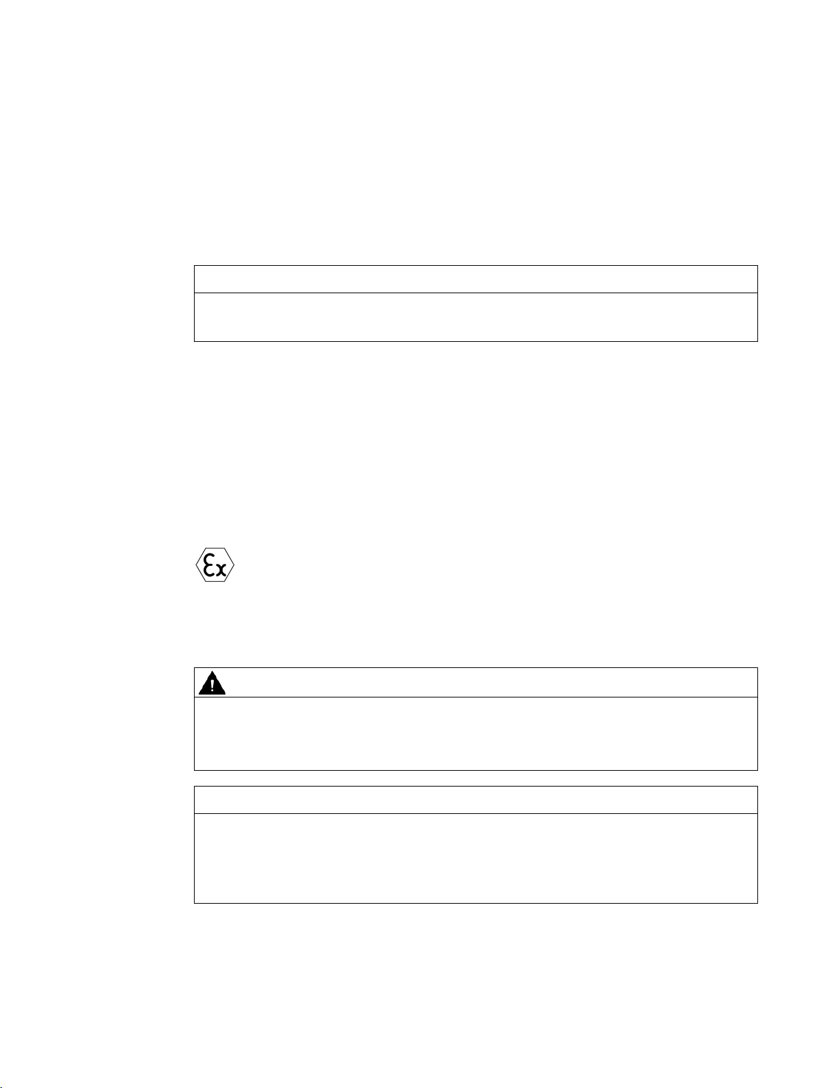
ATEX version gearboxes
The ATEX gearbox fulfills the requirements of the
Directive 2014/34/EU.
In the case of ATEX version gearboxes, please observe the instructions marked
with this symbol.
Note
The performance data assumes an installation altitude of up to 2000
the following ambient temperatures:
•
•
For different installation altitudes and ambient temperatures, please contact Technical
Support.
1.2 Copyright
The copyright to these operating instructions is held by Siemens AG.
These operating instructions must not be wholly or partly reproduced for competitive
purposes, used in any unauthorized way or made available to third parties without
agreement of Siemens AG.
The SIMOGEAR gearboxes described in these operating instructions have been designed
for stationary use in general engineering applications.
Unless otherwise agreed, the gearboxes have been designed for use in plants and
equipment in industrial environments.
The gearboxes have been built based on state-of-the-art technology and are shipped in an
operationally reliable condition. Changes made by users could affect this operational
reliability and are forbidden.
-15° C to +40° C for gearbox types E, Z, D, F, K
-25° C to +40° C for gearbox types B, C
Explosion Protection
m above sea level and
The gearboxes have been designed solely for the application described in the Technical data
(Page 89). Do not operate the gearbox outside the specified power limit. Other operating
conditions must be contractually agreed.
Do not climb on the gearbox. Do not place any objects on the gearbox.
BA 2030
Operating Instructions, 11/2017, A5E37880173A/RS-AE
9
Page 12
General information and safety notes
1.4
Geared motor with encoder for safety-relevant applications
1.5
Obligations of the user
Note the following safety information:
1.4 Geared motor with encoder for safety-relevant applications
For a SIMOGEAR geared motor with encoder for safety-relevant applications, it is crucial
that you observe the operating instructions BA 2730. These operating instructions are valid
for the functionally safe encoders that are mounted onto SIMOGEAR geared motors. The
functionally safe encoders are in compliance with the relevant standards for safety-relevant
applications listed in the declaration of conformity of BA 2730.
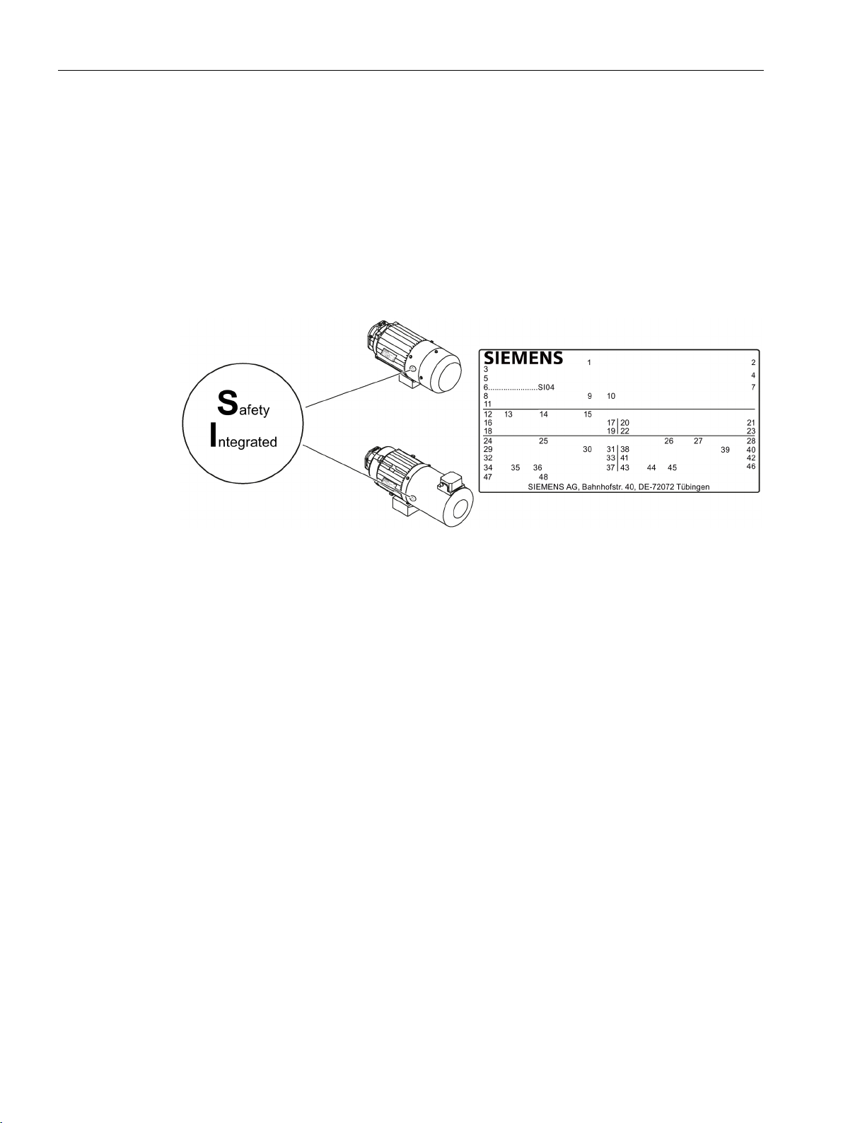
The SIMOGEAR geared motor with functionally safe encoder has a signal yellow marking on
the fan cover. Marking SI04 for the functionally safe encoder is stamped on the rating plate.
The safety level is marked on the functionally safe encoder.
Figure 1-1 Marking for functional safety
The operator must ensure that all persons assigned to work on the geared motor have read
and understood these operating instructions and that they follow them in all points in order
to:
● Eliminate the risk to life and limb of users and other persons.
● Ensure the operational safety of the geared motor.
● Avoid disruptions and environmental damage through incorrect use.
Shut down the geared motors and disconnect the power before you carry out any work on
them.
Make sure that the drive unit cannot be turned on accidentally, e.g. lock the key-operated
switch. Place a warning notice at the drive connection point which clearly indicates that work
is in progress on the geared motor.
Carry out all work with great care and with due regard to "safety".
For all work, observe the relevant regulations for work safety and environment protection.
BA 2030
10 Operating Instructions, 11/2017, A5E37880173A/RS-AE
Page 13

General information and safety notes
1.5 Obligations of the user
Read the instructions on the rating plates attached to the geared motor. The rating plates
must be kept free from paint and dirt at all times. Replace any missing rating plates.
In the event of changes during operation, switch off the drive unit immediately.
Take appropriate protective measures to prevent accidental contact with rotating drive parts,
such as couplings, gear wheels or belt drives.
Take appropriate protective measures to prevent accidental contact with parts and
equipment that heat up to over +70 °C during operation.
When removing protective equipment, keep fasteners in a safe place. Re-attach removed
protective equipment before commissioning.
Collect and dispose of used oil in accordance with regulations. Remove oil spillages
immediately with an oil-binding agent in compliance with environmental requirements.
Do not carry out any welding work on the geared motor. Do not use the geared motor as a
grounding point for welding operations.
Carry out equipotential bonding in accordance with applicable regulations and directives by
electrotechnology specialists.
Do not use high-pressure cleaning equipment or sharp-edged tools to clean the geared
motor.
Observe the permissible tightening torque of the fastening bolts.
Replace damaged bolts with new bolts of the same type and strength class.
Siemens AG accepts the warranty only for original spare parts.
The manufacturer who installs the geared motors in a plant must include the regulations
contained in the operating instructions in its own operating instructions.
BA 2030
Operating Instructions, 11/2017, A5E37880173A/RS-AE
11
Page 14
General information and safety notes
1.6
Particular types of hazards
WARNING
Extreme surface temperatures
WARNING
Hot, escaping oil
WARNING
Poisonous vapors when working with solvents
WARNING
Risk of explosion when working with solvents
WARNING
Risk of eye injury
1.6 Particular types of hazards
Hot surfaces over +55 °C pose a burn risk.
Cold surfaces below 0 °C pose a risk of damage due to freezing.
Do not touch the gearbox without protection.
Before starting any work wait until the oil has cooled down to below +30 °C.
Avoid breathing in vapors when working with solvents.
Ensure adequate ventilation.
Ensure adequate ventilation.
Do not smoke!
Rotating parts can throw off small foreign particles such as sand or dust.
Wear protective eyewear!
In addition to the prescribed personal protection gear, also wear suitable protective gloves
and safety glasses.
BA 2030
12 Operating Instructions, 11/2017, A5E37880173A/RS-AE
Page 15

2
2.1
General technical description
Gearbox housing
Gearbox type
Size
39
49
Helical gearbox E
Cast iron
Cast iron
Parallel shaft gearbox
Cast iron
Cast iron
Bevel gearbox K
Cast iron
Cast iron
Helical worm gearbox C
Cast iron
Cast iron
Geared components
Lubrication
Shaft bearings
The gearbox is supplied with one, two or three transmission stages.
The gearbox is suitable for various mounting positions. Observe the correct oil level.
The housings for sizes 19 and 29 are made of die-cast aluminum.
Depending on the gearbox type, the housings of sizes 39 and 49 are made of die-cast
aluminum or cast iron.
Table 2- 1 Housing material
Helical gearbox D/Z Aluminum Cast iron
Bevel gearbox B Aluminum Aluminum
From size 59, the gearbox housings are made of cast iron.
The geared components are hardened and ground.
For the helical worm gearbox, the worm is hardened and ground. The gear is manufactured
from high-quality bronze.
The bevel gear stage of the bevel gearbox is lapped in pairs.
The geared components are supplied with adequate lubricant by means of dip lubrication.
All shafts are mounted in roller bearings. The roller bearings are lubricated using splash
lubrication or oil-spray lubrication. Bearings that are not supplied with lubricant are closed
and grease-lubricated.
BA 2030
Operating Instructions, 11/2017, A5E37880173A/RS-AE
13
Page 16
Technical description
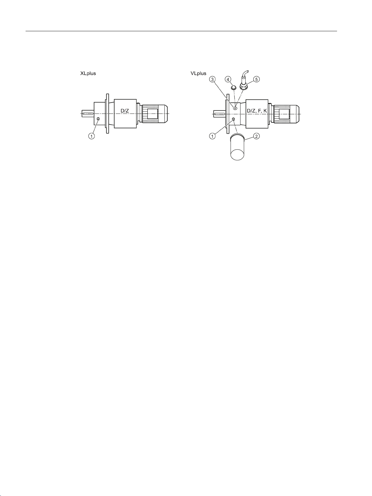
XLplus and VLplus heavy-duty bearing systems
①
Grease nipple
②
Automatic regreasing device (optional)
③
Screw plug
④
Dry-well oil sight glass (optional)
⑤
Dry-well oil sensor (optional)
2.1 General technical description
Figure 2-1 XLplus and VLplus heavy-duty bearing systems
The multi-stage helical gearbox sizes 89-169 can be supplied with an XLplus or VLplus
heavy-duty bearing system.
The parallel-shaft gearbox and the helical gearbox sizes 89-169 can be supplied with a
VLplus heavy-duty bearing system.
With an upstream locating bearing, the bearing system is suitable for high external forces.
The absorbed radial and axial loads are transmitted to the machine via the flange.
The bearings are lubricated independently of the frame size. Initial greasing has already
been carried out. The relubrication is made with the provided grease nipple.
Options for the VLplus heavy-duty bearing system:
An automatic regreasing device
device
A dry-well version with oil sight glass
well version offers increased protection against oil leaks when the output shaft points down.
The flange captures any escaping gear oil for leakages at the oil chamber. The escaping oil
is signaled optically with an oil sight glass
sensor
disconnector approved for ATEX.
② can be installed at any position and can be used underwater.
⑤ is deployed in ATEX version gearboxes, the sensor must be operated with a
② can be supplied as option. The automatic regreasing
④ or oil sensor ⑤ can be supplied as option. The dry-
④ or electronically by an oil sensor ⑤. If the oil
BA 2030
14 Operating Instructions, 11/2017, A5E37880173A/RS-AE
Page 17

Technical description
2.2
Shaft seals
Radial shaft sealing ring
Sealing ring for a longer service life (optional)
Sealing ring to handle increased environmental stress (optional)
2.3
Cooling
NOTICE
Dust deposits prevent heat radiation
2.2 Shaft seals
The shaft sealing rings on the output side prevent lubricant from escaping from the housing
at the shaft outlet and prevent pollution from entering the housing.
The optimum use of the seals depends on the ambient conditions and the lubricant being
used.
A high-quality radial shaft sealing ring is used as standard seal. The ring is provided with an
additional dust lip to protect against contaminants from outside.
The radial shaft sealing ring with dust lip has an additional buffer axial seal towards the
inside of the gearbox. The buffer axial seal has a sinusoidal sealing lip that protects the
sealing ring from contaminations.
The sealing ring is equipped with an additional fiber disk. In addition to the longer service life,
the disk also provides increased protection against higher environmental stress as a result of
moisture and dust.
Dust deposits prevent heat radiation and cause a high housing temperature.
Keep the gearbox free from dirt, dust, etc.
The gearbox does not normally require additional cooling. The generously dimensioned
housing surface is sufficient for dissipating heat losses where there is free convection. If the
housing temperature exceeds a value of +80 °C, please contact Technical Support.
BA 2030
Operating Instructions, 11/2017, A5E37880173A/RS-AE
15
Page 18

Technical description
2.4
Rating plate
2.5
Surface treatment
2.5.1
General information on surface treatment
ATEX version gearboxes
The gearbox is delivered complete with primer and paint finish.
If the gearbox is delivered with primer only or unpainted, a paint finish must be
applied which meets the applicabl
primer does not provide adequate corrosion protection.
ATEX version gearboxes
When applying conductive paint, the operator must ensure that the paint rem
in a perfect state.
The paint finish must be checked at intervals of approximately 2 - 3 years.
ATEX version gearboxes
An excessively high electrostatic charge must be avoided.
Ensure that highly
charge are avoided.
Highly active mechanisms that can generate charges:
•
•
•
2.4 Rating plate
The rating plate on the gearbox or geared motor is of coated aluminum foil. The rating plate
is glued using a special masking film. The film ensures permanent resistance to UV radiation
and media of all kinds, such as oils, greases, salt water and cleaning agents.
The adhesive and the material ensure firm adhesion and long-term legibility within the
operating temperature range from -40 °C to +155 °C.
The edges of the rating plate are paint-finished to match the color of the gearbox or motor to
which it is affixed.
All paint finishes are sprayed on.
e guidelines for the specific application. The
Fast air with high dust content directed past the gearbox
Sudden escape of compressed gases that contain particles
Harsh abrasive processes (this does not mean manual cleaning / wiping with
cleaning cloths)
active mechanisms that cause the paint finish to generate a
ains
BA 2030
16 Operating Instructions, 11/2017, A5E37880173A/RS-AE
Page 19

Technical description
NOTICE
Failure of the external protection
Note
Information ab
product supplied by your supplier.
Only the paint manufacturer is liable for the quality and compatibility.
2.5.2
Painted version
Paint system
Description
Corrosiveness category C1, unpainted for gearbox and motor housings made of aluminum
Corrosiveness category C1 for normal environmental stress
2.5 Surface treatment
If the paint finish is damaged, the geared motor may corrode.
Do not damage the paint finish.
out the ability to be repainted does not guarantee the quality of the paint
The corrosion protection system is classified according to the corrosiveness categories in
DIN EN ISO 12944-2.
Table 2- 2 Paint according to corrosiveness categories
-
1-component hydro paint, top coat
• Indoor installation
• Heated buildings with neutral atmospheres
• Resistance to greases and some resistance to
mineral oils, aliphatic solvents
• Standard
• Indoor installation
• Heated buildings with neutral atmospheres
• Resistance to greases and some resistance to
mineral oils, aliphatic solvents
• Standard paint for gearbox housings made of cast
iron
BA 2030
Operating Instructions, 11/2017, A5E37880173A/RS-AE
17
Page 20

Technical description
Paint system
Description
Corrosiveness category C2 for low environmental stress
Corrosiveness category C3 for medium environmental stress
Corrosiveness category C4 for high environmental stress
2.5 Surface treatment
2-component - polyurethane top coat
2-component epoxy zinc phosphate base
coat,
2-component polyurethane top coat
2-component epoxy zinc phosphate base
coat,
2-component polyurethane top coat
• Indoor and outdoor installation
• Unheated buildings with condensation, production
areas with low humidity, e.g. warehouses and sports
facilities
• Atmospheres with little contamination, mostly rural
areas
• Resistance to greases, mineral oils and sulfuric
acid (10 %), caustic soda (10 %) and some
resistance to aliphatic solvents
• Indoor and outdoor installation
• Production areas with high humidity and some air
contamination, e.g. food production areas, dairies,
breweries and laundries
• Urban and industrial atmospheres, moderate
contamination from sulfur dioxide, coastal areas with
low salt levels
• Resistance to greases, mineral oils, aliphatic
solvents, sulfuric acid (10 %), caustic soda (10 %)
• Indoor and outdoor installation
• Chemical plants, swimming pools, wastewater
treatment plants, electroplating shops, and
boathouses above seawater
• Industrial areas and coastal areas with moderate salt
levels
• Resistance to greases, mineral oils, aliphatic
solvents, sulfuric acid (10 %), caustic soda (10 %)
BA 2030
18 Operating Instructions, 11/2017, A5E37880173A/RS-AE
Page 21

Technical description
Paint system
Description
Corrosiveness category C5 for very high environmental stress
2.5.3
Primed version
Paint system
Can be overpainted with
Unpainted corrosiveness category C1
Primed according to corrosiveness category C2 G
Primed according to corrosiveness category C4 G
2.5 Surface treatment
2-component epoxy zinc phosphate base
coat,
2-component polyurethane intermediate
coat,
2-component polyurethane top coat
• Indoor and outdoor installation
• Buildings and areas with almost constant
condensation and high contamination, e.g. malt
factories and aseptic areas
• Industrial areas with high humidity and aggressive
atmosphere, coastal areas and offshore
environments with high salt levels
• Resistance to greases, mineral oils, aliphatic
solvents, sulfuric acid (10 %), caustic soda (20 %)
In case of corrosiveness category C1, overpainting with a 1-component hydrosystem after
prior rubbing down is possible.
In case of corrosiveness categories C2 to C5, overpainting with 2-component polyurethane
paint, 2-component epoxide paint and 2-component acrylic paint after prior rubbing down is
possible.
Table 2- 3 Primer according to corrosiveness category
Cast iron parts immersion primed,
steel parts primed or zinc-plated,
aluminum and plastic parts untreated
2-component epoxy zinc phosphate,
nominal layer thickness 60 µm
2-component epoxide zinc phosphate,
desired coat thickness 120 μm
• Synthetic paint, synthetic resin paint, oil paint
• 2-component polyurethane paint
• 2-component epoxy paint
• 2-component polyurethane paint
• 2-component epoxy paint
• 2-component acrylic paint
• Acid-hardening paint
• 2-component polyurethane paint
• 2-component epoxy paint
• 2-component acrylic paint
• Acid-hardening paint
BA 2030
Operating Instructions, 11/2017, A5E37880173A/RS-AE
19
Page 22

Technical description
2.5 Surface treatment
BA 2030
20 Operating Instructions, 11/2017, A5E37880173A/RS-AE
Page 23

3
3.1
Incoming goods
NOTICE
Transport damage impairs correct functioning
Note
Do not open or damage parts of the packaging that preserve the product.
Note
Check that the technical specifications are in accordance with the purchase order.
Inspect the delivery immed
Notify the freight company of any damage caused during transport immediately (this is the
only way to have damage rectified free of charge). Siemens AG will not accept any claims
relating to item
3.2
Transport
3.2.1
General information on transport
NOTICE
The use of force will damage the gearbox or geared motor
Do not commission faulty gearboxes or geared motors.
iately on arrival for completeness and any transport damage.
s missing from the delivery and which are submitted at a later date.
The gearbox or geared motor is delivered in a fully assembled condition. Additional items are
sometimes delivered packaged separately.
The products supplied are listed in the dispatch papers.
Transport the gearbox or geared motor carefully. Avoid knocks.
Before putting the drive into operation, remove any transport fixtures and keep them safe or
render them ineffective. You can then use them again for transporting further items or you
can apply them again.
BA 2030
Operating Instructions, 11/2017, A5E37880173A/RS-AE
21
Page 24
Incoming goods, transport, and storage
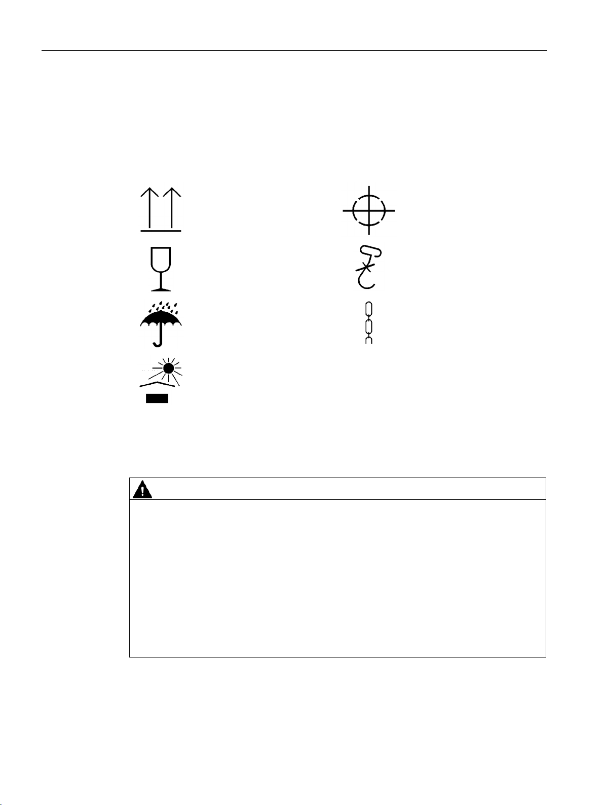
This way up
Center of gravity
Fragile
Do not use hand hook
Keep dry
Attach here
Keep cool
3.2.2
Fastening for suspended transport
WARNING
Inadequately secured gearbox or geared motors can free themselves
3.2 Transport
Different forms of packaging may be used, depending on the size of the gearbox or geared
motor and the method of transport. Unless contractually agreed otherwise, the seaworthy
packaging complies with HPE Packaging Guidelines (Bundesverband Holzpackmittel
Paletten Exportverpackungen e.V., the German Federal Association for wooden packaging,
pallets, and export packaging).
Note the symbols which appear on the packaging. These have the following meanings:
Use only the transport eye or eyebolt of the gearbox to transport the gearbox or geared
motor. Because they are designed only for the weight of the gearbox or geared motor, it is
not permissible to add additional loads.
Do not rig eyebolts to the front threads at the shaft ends for transportation purposes.
Do not use the integrally cast lifting eyes on the motor for transport because of the risk of
breaking.
If necessary, use additional, suitable lifting accessories for transport or during installation.
When attaching by a number of chains and ropes just two strands must be sufficient to bear
BA 2030
the entire load. Secure lifting accessories against slipping.
22 Operating Instructions, 11/2017, A5E37880173A/RS-AE
Page 25
Incoming goods, transport, and storage
Thread size
m
d3
Thread size
m
d3
[kg]
[mm]
[kg]
[mm]
M8
140
36
M20
1 200
72
M10
230
45
M24
1 800
90
M16
700
63 - -
-
3.3
Storage
3.3.1
General information for storage
WARNING
Danger of serious injuries caused by falling objects
Danger of damage to the gearbox when stacked
NOTICE
Failure of the external protection
3.3 Storage
Table 3- 1 Maximum load of the eyebolt on the gearbox
M12 340 54 M30 3 200 108
The eyebolt corresponds to DIN 580.
Do not stack gearboxes or geared motors on each other.
Mechanical damage, chemical damage and thermal damage, such as scratches, acids,
alkalis, sparks, welding beads and heat cause corrosion.
Do not damage the paint finish.
Unless contractually agreed otherwise, the guarantee period for the standard preservative
lasts 6 months from the date of delivery.
In the case of storage in transit over 6 months, special arrangements must be made for
preservation. Please contact Technical Support.
Store the gearbox or geared motor in dry, dust-free rooms that are maintained at a constant
temperature.
The storage location must be vibration- and shock-free.
The free shaft ends, sealing elements and flange surfaces must have a protective coating.
BA 2030
Operating Instructions, 11/2017, A5E37880173A/RS-AE
23
Page 26

Incoming goods, transport, and storage
3.3.2
Storage up to 36 months with long-term preservation (optional)
3.3.2.1
General notes for storage up to 36 months
3.3.2.2
Gearbox filled with operating oil and anti-corrosive agent
NOTICE
Damage to the gearbox caused by incorrect oil quantities
3.3.2.3
Gearbox completely filled with oil
NOTICE
Damage to the gearbox caused by incorrect oil quantities
3.3 Storage
Store the gearbox or geared motor in dry, dust-free rooms that are maintained at a constant
temperature. Special packing is then not necessary.
If such premises are not available, pack the gearbox or the geared motor in plastic film or airtight sealed film and materials. The films and materials must be able to accept moisture.
Cover them to provide protection against heat, direct sunlight and rain.
The permissible ambient temperature is -25 °C to +50 °C.
The life of the corrosion protection is 36 months from delivery.
Check the oil level before commissioning.
Observe the information and procedures for Checking the oil level (Page 67).
The gearbox is filled with oil corresponding to the mounting position so that it is ready for
operation, and is sealed airtight using a screw plug or with a pressure breather valve with
transport fixture.
For storage up to 36 months, a VCI anti-corrosion agent (Volatile Corrosion Inhibitor) is
added.
Prior to commissioning, remove excessive oil until it has the correct oil level.
Observe the information and procedures for Correcting the oil level (Page 67).
When biodegradable oils or oils for the food-processing sector are used, the gearbox is filled
completely with operating oil. The gearbox is closed air-tight with a sealing plug or a
pressure venting with transport fixture.
Do not lower the oil level during short-time commissioning for 10 minutes in no-load
operation.
BA 2030
24 Operating Instructions, 11/2017, A5E37880173A/RS-AE
Page 27
4
4.1
Unpacking
NOTICE
Transport damage impairs the correct function of the gearbox
4.2
General information on installation
ATEX version gearboxes
Effect on bearings of stray electric currents from electrical equipment.
When mounting the gearbox on or connecting it to the machine, take care to
ensure potential equalization. The information on grounding and equipotential
bonding provided by the motor supplier must be observed.
WARNING
Operating under load
NOTICE
Destruction caused by welding
Never commission faulty gearboxes.
Check the gearbox for completeness and for damage. Report any missing parts or damage
immediately.
Remove and dispose of the packaging material and transport equipment in compliance with
regulations.
Under load, the system can start or reverse in an uncontrolled fashion.
The entire system must be load-free so that there is no danger during this work.
Welding destroys the geared parts and bearings.
Do not weld on the gearbox. The gearbox must not be used as a grounding point for
welding operations.
BA 2030
Operating Instructions, 11/2017, A5E37880173A/RS-AE
25
Page 28

Installation
NOTICE
Overheating caused by solar radiation
NOTICE
Malfunction resulting from foreign objects
NOTICE
Damaged components impair the correct function of the gearbox
NOTICE
Violation of the maximum permissible oil sump temperature
4.2 General information on installation
Overheating of the gearbox due to exposure to direct sunlight.
Provide suitable protective equipment such as covers or roofs. Prevent heat accumulation.
The operator must ensure that no foreign objects impair the function of the gearbox.
If any components are damaged, the correct function of the gearbox will no longer be
ensured.
Do not install any damaged gearbox components.
The oil sump temperature may be exceeded if the temperature monitoring equipment is
incorrectly set.
An alarm must be output when the maximum permissible oil sump temperature is reached.
The geared motor must be switched off when the maximum permissible temperature is
exceeded. If the geared motor is shut down, then this can cause the machine to come to a
stop.
Exercise particular care during mounting and installation. The manufacturer cannot be held
liable for damage caused by incorrect mounting and installation.
Make sure that there is sufficient space around the gearbox or geared motor for mounting,
maintenance and repair.
On geared motors with a fan, leave sufficient free space for the entry of air. Observe the
installation conditions for the geared motor.
Provide sufficient lifting gear at the start of mounting and fitting work.
Observe the mounting position specified on the rating plate. This ensures that the correct
quantity of lubricant is provided.
Use all the fastening means that have been assigned to the particular mounting position and
mounting type.
Cap bolts cannot be used in some cases due to a lack of space. In such cases, please
contact Technical Support quoting the type of gearbox.
BA 2030
26 Operating Instructions, 11/2017, A5E37880173A/RS-AE
Page 29

Installation
4.3
Thread sizes and tightening torques for fastening bolts
Thread size
Tightening torque for strength class
8.8
10.9
12.9
[Nm]
[Nm]
[Nm]
M4 3 4
5
M5 6 9
10
M6
10
15
18
M10
50
70
85
M16
210
295
355
M20
450
580
690
M24
750
1 000
1 200
M30
1 500
2 000
2 400
M36
2 500
3 600
4 200
4.3 Thread sizes and tightening torques for fastening bolts
The general tolerance for the tightening torque is 10 %. The tightening torque is based on a
friction coefficient of μ = 0.14.
Table 4- 1 Tightening torques for fastening bolts
M8 25 35 41
M12 90 120 145
BA 2030
Operating Instructions, 11/2017, A5E37880173A/RS-AE
27
Page 30

Installation
4.4
Gearbox with foot mounting
NOTICE
Impermissible housing loadings when unevenness present
Helical gearbox
Parallel shaft
gearbox F
Bevel gearbox
B, K
Helical worm
gearbox C
Thread size
E
D/Z
Size
M8 - 19, 29, 39
29, 39
B19, B29, B39
29
M10
39 - 49
B49, K39, K49
39, 49
M12
49
49, 59, 69
69, 79
K69, K79
69
M16
69, 89
79, 89
89, 109
K89
89
M20
109, 129
109
129
K109
-
M24
-
129
149
K129
-
M30
149
149
169
K149
-
M36
-
169, 189
189
K169, K189
-
4.4 Gearbox with foot mounting
Do not subject the gearbox to excessive stress when tightening the fastening bolts.
The foundation must be level and free from dirt.
The deviation in flatness of the gearbox's contact surface may not exceed the following
values:
For gearboxes up to size 89: 0.1 mm
For gearboxes from size 109: 0.2 mm.
The foundation should be designed in such a way that no resonance vibrations are created
and no vibrations are transmitted from adjacent foundations.
The foundation structure on which the gearbox is to be mounted must be torsionally rigid. It
must be dimensioned according to the weight and torque, taking into account the forces
acting on the gearbox. If the substructure is too weak, it will cause radial or axial
displacement offset during operation that cannot be measured at a standstill.
If the gearbox is fastened to a concrete foundation, use foundation blocks for the appropriate
recesses.
Align and grout the slide rails into the foundation.
Align the gearbox carefully with the units on the input and output side. Take into account the
elastic deformation due to operating forces.
Prevent displacement from external forces due to lateral impacts.
Use stud bolts or headless screws of strength class 8.8 or higher for the mounting foot.
Observe the tightening torque.
Table 4- 2 Thread size of the fastening bolt
BA 2030
28 Operating Instructions, 11/2017, A5E37880173A/RS-AE
Page 31

Installation
4.5
Gearbox with flange fastening
Note
Siemens
flange and mounting surface.
Thread
size
Flange
Helical gearbox
E, D/Z
Parallel shaft
gearbox F
Bevel gearbox
B, K
Helical worm
gearbox C
Size
M6
A120
19, 29, 39
29
B29
29
M8
A140, A160
19, 29, 39, 49, 59
29, 39
B29, B39, K39
39
M10
A200
39, 49, 59, 69
49
B39, B49, K49
49, 69
109
M16
A350
89, 109, 129, 149
109
K109
-
M16
A450
109, 129, 149, 169
129, 149
K129, K149
-
M16
A550
169, 189
169
K169
-
M20
A660
189
189
K189
-
Gearbox
size
Flange
Strength class for motor size
90
100
112
132
160
180
200
225
250
280
315
39
A160
10.9
10.9
- - - - - - - - -
49
A200
8.8
10.9
10.9
10.9
- - - - - - -
69
A250
8.8
8.8
8.8
10.9
- - - - - - -
79
A250
8.8
8.8
8.8
10.9
10.9
- - - - -
-
89
A300
8.8
10.9
10.9
10.9
10.9
10.9
- - - - -
129
A450
8.8
8.8
8.8
8.8
8.8
8.8
8.8
8.8 - -
-
169
A550
- - 8.8
8.8
8.8
10.9
10.9
10.9
10.9
10.9
-
189
A660
- - 8.8
8.8
8.8
8.8
8.8
8.8
10.9
10.9
10.9
4.5 Gearbox with flange fastening
AG recommends an anaerobic adhesive to enhance the friction lock between
Table 4- 3 Thread size of the fastening bolt
M12 A250, A300 49, 59, 69,79,89,
69, 79, 89 K69, K79, K89 89
Use screws / nuts of strength class 8.8 for gearboxes with a flange-mounted design.
Note the following exceptions:
Table 4- 4 Strength class of the fastening bolt for FF/FAF and KF/KAF
109 A350 8.8 8.8 8.8 8.8 10.9 10.9 10.9 10.9 - - -
149 A450 - 8.8 8.8 8.8 8.8 8.8 10.9 10.9 10.9 - -
BA 2030
Operating Instructions, 11/2017, A5E37880173A/RS-AE
29
Page 32

Installation
Gearbox size
Flange
Strength class
E
D/Z
39
29, 39
A120
10.9 1)
-
49
A140
69
69
A200
89
79
A250
109
89
A300
129, 149
109, 129
A350
-
149, 169
A450
-
189
A550
1) Use suitable washers under the nuts / bolt heads
4.6
Gearboxes in foot or flange version
NOTICE
Impermissible housing loadings caused by incorrectly installed add-on elements
4.6 Gearboxes in foot or flange version
Table 4- 5 Strength class of the fastening bolt / nut for EZ, EF, DZ/ZZ and DF/ZF
10.9
49 59 A160
Do not subject the gearbox housing to excessive stress by adding add-on elements to the
foot or flange.
Add-on elements must not transmit forces, torques, and vibrations to the gearbox.
To prevent strains on the housing, fasten the gearbox only on the flange or the foot fastening
for force and torque transmission. Refer to Gearbox with foot mounting (Page 28).
The second mounting option (foot or flange) is intended for add-on elements, e.g. protection
covers with an intrinsic weight of up to max. 30 % of the weight of the gearbox.
BA 2030
30 Operating Instructions, 11/2017, A5E37880173A/RS-AE
Page 33

Installation
4.7
Mounting an input or output element on the gearbox shaft
WARNING
Risk of burns caused by hot parts
NOTICE
Damage to shaft sealing rings caused by solvent
NOTICE
Damage to shaft sealing rings caused by heating
NOTICE
Premature wear or material damage due to misalignment
NOTICE
Damage caused by improper handling
Note
Deburr the parts of elements to be fitted in the ar
Recommendation:
4.7 Mounting an input or output element on the gearbox shaft
Do not touch the gearbox without protection.
Avoid any contact of solvent or benzine with the shaft sealing rings.
Use thermal shields to protect shaft sealing rings from heating above 100 °C due to radiant
heat.
Misalignment caused by excessive angular or axis displacement to the connecting shaft
ends.
Ensure precise alignment of the individual components.
Bearings, housing, shaft and locking rings are damaged due to improper handling.
Do not use impacts or knocks to force the input and output elements to be mounted onto
the shaft.
ea of the hole or keyways.
0.2 x 45°
Where couplings are to be fitted in a heated condition, observe the specific operating
instructions for the coupling. Unless otherwise specified, apply the heat inductively using a
torch or in a furnace.
Use the center holes in the shaft end faces.
BA 2030
Operating Instructions, 11/2017, A5E37880173A/RS-AE
31
Page 34

Installation
Correct
Incorrect
a
Hub
F
Force
Procedure
4.7 Mounting an input or output element on the gearbox shaft
Use a fitting device to fit the input or output elements.
Figure 4-1 Example of a fitting device
Observe the correct mounting arrangement to minimize stress on shafts and bearings due to
lateral forces.
Figure 4-2 Mounting arrangement for low stress on shafts and bearings
1. Use either benzine or solvent to remove the anti-corrosion protection from the shaft ends
and flanges or remove the applied protective skin.
2. Fit the drive input and output elements to the shafts. Fasten the elements when
necessary.
You have now fitted the input or output element.
BA 2030
32 Operating Instructions, 11/2017, A5E37880173A/RS-AE
Page 35

Installation
4.8
Removing and installing the protection cover
ATEX version gearboxes
Sparks may be caused by a damaged protection cover. Replace damaged
protection covers immediately.
Secure bolts ① with, e.g. Loctite 243 medium-strength adhesive.
①
Bolt ③ Flat seal
②
Protection cover
④
Gearbox housing
Procedure
4.8 Removing and installing the protection cover
The protection cover of the hollow shaft is delivered ready-fitted to the gearbox flange.
Dismantle the protection cover for installation of the output shaft.
Figure 4-3 Protection cover for hollow shaft
1. Unscrew the bolts ① and remove the protection cover ② together with the flat
gasket
2. Fit the output shaft.
3. Use a suitable cleaning agent to clean the contact surface of the protection cover
the gearbox.
4. Ensure that the flat seal
5. Wet the bolts
6. Screw on the protection cover
7. Protect all remaining bare areas with a suitable permanent anti-corrosive agent.
You have now installed the protection cover for operation.
③.
③ is correctly seated.
① with medium-strength adhesive, e.g. Loctite 243.
②.
② on
BA 2030
Operating Instructions, 11/2017, A5E37880173A/RS-AE
33
Page 36

Installation
4.9
Installing and removing the shaft-mounted gearbox
4.9.1
General information on installing the shaft-mounted gearbox
NOTICE
Damage to shaft sealing rings caused by solvent
NOTICE
Subjecting stress to the hollow shaft causes bearing failure
NOTICE
For shrink disks:
Lubricants in the area between the hollow shaft and machine shaft impair torque
transmission
Note
Coat the contact surfaces with the mounting paste supplied with the product or any suitable
lubricant to prevent frictional
Note
Observe the permissible concentricity tolerance of the cylindrical shaft extension of the
machine shaft to the housing axle according to DIN
4.9 Installing and removing the shaft-mounted gearbox
Avoid any contact of solvent or benzine with the shaft sealing rings.
Skewing or stressing the hollow shaft increases the loading. This can cause bearing failure.
The hollow shaft must be flush with the machine shaft to avoid misalignment.
Do not subject the hollow shaft to axial and radial stress.
Keep the bore in the hollow shaft and the machine shaft completely grease-free.
Do not use impure solvents and soiled cleaning cloths.
corrosion.
42955.
BA 2030
34 Operating Instructions, 11/2017, A5E37880173A/RS-AE
Page 37

Installation
4.9.2
Hollow shaft with parallel key
4.9.2.1
Mounting the hollow shaft with parallel key
*
Not included in scope of supply
①
Machine shaft
⑥
Circlip
②
Hollow shaft
⑦
Parallel key
③
Hexagon nut
⑧
Mounting paste
④
Threaded spindle
⑨
Bolt
⑤
Disk
⑩
Sealing caps
Procedure
Thread size
M5
M6
M8
M10
M12
M16
M20
M24
M30
Tightening torque [Nm]
5 8 8
14
24
60
120
200
400
4.9 Installing and removing the shaft-mounted gearbox
Figure 4-4 Mounting the hollow shaft with parallel key
Instead of the nut and threaded spindle shown in the diagram, other types of equipment such
as hydraulic lifting equipment may be used.
1. Using benzine or a solvent, remove the anti-corrosion protection from the shaft ends and
flanges.
2. Check the seats or edges of the hollow and machine shafts for damage. Contact
Technical Support if you notice any damage.
3. Apply the mounting paste provided
4. Fit the gearbox using the disk
the hollow shaft
5. Replace the nut
the specified torque.
6. Close the open hollow shaft end using a sealing cap
You have mounted the hollow shaft with feather key.
Table 4- 6 Tightening torque for the screw
②.
③ and the threaded spindle ④ with a screw ⑨. Tighten the bolts ⑨ to
① to the machine shaft ⑧. Apply the paste uniformly.
⑤, threaded spindle ④ and nut ③. Support is provided by
⑩.
BA 2030
Operating Instructions, 11/2017, A5E37880173A/RS-AE
35
Page 38

Installation
4.9.2.2
Removing the hollow shaft with parallel key
WARNING
Inadequately secured gearbox or geared motors can free themselves
NOTICE
Subjecting stress to the hollow shaft causes bearing failure
NOTICE
Excessive forces during removal
Note
If frictional corrosion has occurred on the seat surfaces, use rust solvent to facilitate the
removal of the gearbox. Allow an adequately long time for the rust solvent to take effect.
Items ① to ⑤ are not included in the scope of supply.
①
Disk
④
Hexagon nut
②
Threaded block
⑤
Leadscrew
③
Parallel key
4.9 Installing and removing the shaft-mounted gearbox
Before driving out the machine shaft, fasten a suitably dimensioned means of absorbing
load to the gearbox.
Slightly pretension the pulling equipment so that the gearbox does not drop onto it when the
insert shaft is released.
It is essential to prevent misalignment when removing the unit.
Excessive forces can occur during removal of the hollow shaft via the housing.
Stresses in the hollow shaft can lead to bearing failure and damage to the gearbox housing.
Figure 4-5 Removing the hollow shaft with parallel key
BA 2030
36 Operating Instructions, 11/2017, A5E37880173A/RS-AE
Page 39

Installation
Procedure
Design suggestion for threaded block and disk
Gearbox
Size
Hollow
shaft ∅
b10
b11
b12
d10
d11
s11
t
max
u
[mm]
[mm]
[mm]
[mm]
[mm]
[mm]
[mm]
[mm]
[mm]
B
19
20 3 15
10
19.9
10
M6
22.5
6
B, F
29
25 3 15
10
24.9
16
M10
28
8
C
25 3 15
10
24.9
16
M10
28
8
B, K, F, C
30 6 15
10
29.9
18
M10
33
8
B
35 6 15
10
34.9
24
M12
38
10 B 40 6 15
10
39.9
28
M16
43
12
C
30 6 15
10
29.9
18
M10
33
8
K, F, C
35 6 15
10
34.9
24
M12
38
10 B 40 6 15
10
39.9
28
M16
43
12
K, F, C
40 6 20 9 39.9
28
M16
43
12
C
45 6 20 9 44.9
36
M16
48
14
K, F
79
40 6 20 9 39.9
28
M16
43
12
K, F, C
50 7 20
10
49.9
36
M16
53.5
14 C 60 7 20
10
59.9
45
M20
64
18
K, F
109
60
10
24
14
59.9
45
M20
64
18
K, F
129
70
10
24
14
69.9
54
M20
74.5
20
K, F
149
90
10
24
14
89.9
72
M20
95
25
K, F
169
100
10
30
15
99.9
80
M24
106
28
K, F
189
120
10
30
15
109.9
80
M24
127
32
4.9 Installing and removing the shaft-mounted gearbox
1. Remove the axial locking element from the hollow shaft.
2. Drive out the machine shaft using the disk
threaded spindle
⑤ and hexagon nuts ④.
①, threaded block ②, feather key ③,
You have now removed the hollow shaft with parallel key.
B, C 29 20 3 15 10 19.9 10 M6 22.5 6
39
49
69
89
BA 2030
Operating Instructions, 11/2017, A5E37880173A/RS-AE
37
Page 40

Installation
4.9.3
Hollow shaft with shrink disk
4.9.3.1
Mounting the hollow shaft with shrink disk
a
Greased
b
Absolutely grease-free
*
Not included in scope of supply
①
Machine shaft
②
Hollow shaft
③
Bushing
Procedure
4.9 Installing and removing the shaft-mounted gearbox
Figure 4-6 Mounting the hollow shaft with shrink disk
1. Using benzine or a solvent, remove the anti-corrosion protection from the shaft ends and
flanges.
2. Check the seats or edges of the hollow and machine shafts for damage. Contact
Technical Support if you notice any damage.
3. Mount the gearbox with the shrink disk shaft onto the machine shaft. Carefully ensure the
correct position and that the shrink disk seat completely covers the machine shaft.
You have mounted the hollow shaft with shrink disk.
BA 2030
38 Operating Instructions, 11/2017, A5E37880173A/RS-AE
Page 41

Installation
4.9.3.2
Mounting the shrink disk
WARNING
Risk of injury due to freely rotating parts
NOTICE
Lubricants in the shrink disk seat impair torque transmission
NOTICE
Plastic deformation of the hollow shaft caused by tightening the tightening bolts
NOTICE
Avoid overloading the individual bolts
Note
The shri
Do not dismantle it before the initial fitting.
Note
The machine shaft material must comply with the following criteria in order to safely and
reliably transfer the forces and torques.
•
•
•
4.9 Installing and removing the shaft-mounted gearbox
Fit a cover cap or protection cover.
Keep the bore in the hollow shaft and the machine shaft completely grease-free.
Do not use impure solvents and soiled cleaning cloths.
Plastic deformation of the hollow shaft when tightening the tightening bolts before fitting the
machine shaft.
First fit machine shaft. Then tighten the tightening bolts.
Do not exceed the maximum tightening torque for the tightening bolt.
Frame sizes 29 - 69:
tighten clamping screws
Frame sizes 79 - 189:
it is important that the face surfaces of the outer ring
one another. If they are not flush with one another when tensioning, the tolerance of the
insert shaft must be checked.
Yield point Re ≥ 360 N/mm2
Modulus of elasticity: approx. 206 kN/mm2
No face end thread in the machine shaft because it would reduce the transferred torque
⑥
④ and the inner ring ⑤ are flush with
nk disk, item ③, is delivered ready for installation.
BA 2030
Operating Instructions, 11/2017, A5E37880173A/RS-AE
39
Page 42

Installation
Note
The shrink
Note
Apply
Note
Coat with a suitable lubricant to prevent frictional corrosion of the contact surface on the
customer's machine shaft in the vicinity of the bush.
Sizes 29 - 69
Sizes 79 - 189
a
Greased
b
Absolutely grease-free
①
Machine shaft
②
Hollow shaft
③
Shrink disk comprising items ④ - ⑥
④
Outer ring
⑤
Inner ring
⑥
Tightening bolt
4.9 Installing and removing the shaft-mounted gearbox
-fitted disc connection fastens the hollow shaft axially on the machine shaft.
a thin layer of grease to the shrink disk seat on the hollow shaft.
Figure 4-7 Mounting the shrink disk
BA 2030
40 Operating Instructions, 11/2017, A5E37880173A/RS-AE
Page 43

Installation
Procedure
Gearbox size
Thread size
Strength class
Tightening torque
[Nm]
29
M5
8.8 5 39, 49, 69
M6
8.8
12
109
M10
12.9
70
129
M10
12.9
70
149
M12
12.9
121
169, 189
M14
12.9
193
4.9 Installing and removing the shaft-mounted gearbox
1. Push the shrink disk ③ onto the hollow shaft ③.
– 3-part shrink disk until the limit for sizes 29 - 69.
– 2-part shrink disk flush with the shaft end for sizes 79 - 189.
2. Tighten the clamping bolts
⑥, initially by hand. Align the shrink disk ③ so that the
clamping flanges are plane-parallel with one other.
3. Use the torque wrench to turn each of the clamping screws
⑥ equally by 1/6 revolution
(not crosswise); repeat this procedure several times. Observe the tightening torque.
4. Attach the rubber cover or protection cover included in the scope of supply,
see Removing and installing the protection cover (Page 33).
You have now installed the shrink disk.
Table 4- 7 Tightening torque for the tightening bolt
79, 89 M8 12.9 35
BA 2030
Operating Instructions, 11/2017, A5E37880173A/RS-AE
41
Page 44

Installation
4.9.3.3
Pulling off the shrink disk
Procedure
4.9.3.4
Cleaning and lubricating shrink disks
Procedure
Lubricant
Sold as
Manufacturer
Molykote 321 R (lubricant paint)
Molykote G Rapid
Spray or paste
Unimily P5
Powder
Aemasol MO 19 P
Spray or paste
A. C. Matthes
4.9 Installing and removing the shaft-mounted gearbox
1. Successively release the tightening bolts ⑥ one after the other through a ¼ turn each
time using a wrench. Do not completely remove the bolts.
2. Pull the shrink disk off the hollow shaft.
Sizes 79 - 189:
If the outer ring does not come away from the inner ring, remove some of the tightening bolts
and insert them into neighboring forcing threads.
Pull the shrink disk off the hollow shaft.
Soiled shrink disks must be cleaned and regreased prior to fitting.
Shrink disks that have been released need not be disassembled and regreased before being
retensioned.
1. Only grease the inner friction surfaces of the shrink disks. To do this, use a solid lubricant
with a friction coefficient of μ = 0.04.
2. Use a paste containing MoS
to grease the bolts, applying the paste to the thread and
2
underneath the head.
Clean the shrink disk.
Table 4- 8 Lubricants for shrink disks
Spray DOW Corning
Molykote spray (powder spray)
Molykombin UMFT 1 Spray Klüber Lubrication
BA 2030
42 Operating Instructions, 11/2017, A5E37880173A/RS-AE
Page 45

Installation
4.9.4
SIMOLOC assembly system
4.9.4.1
General notes for the SIMOLOC assembly system
WARNING
Risk of injury due to freely rotating parts
NOTICE
Damaged components impair the correct function of the gearbox
NOTICE
Lubricant on the machine shaft ① impairs the torque transmission
NOTICE
Avoid overloading the individual bolts
Note
The SIMOLOC assembly system secures the hollow shaft axially on the machine shaft.
Note
In the hollow shaft
bushing
Oil type of the provided oil: CLP
Note
The thrust collar
Note
Before installing the SIMOLOC, mount the torque arms
4.9 Installing and removing the shaft-mounted gearbox
Fit a cover cap or protection cover.
If any components are damaged, the correct function of the gearbox will no longer be
ensured.
Do not install any damaged gearbox components.
Keep the bore in the tapered bushing ⑨ and the machine shaft ① completely grease-free.
Do not use impure solvents and soiled cleaning cloths.
Do not exceed the maximum tightening torque for the tightening bolts ④ und ⑩.
⑥, oil the locating hole for the tapered bushing ⑨ and bronze
② lightly with the provided oil.
VG 68 DIN 51517-3
⑤ must be placed at the correct position as in the delivered state.
⑦ on the gearbox.
BA 2030
Operating Instructions, 11/2017, A5E37880173A/RS-AE
43
Page 46

Installation
4.9.4.2
Installing SIMOLOC
a
Absolutely grease-free
⑦
Torque arm
①
Machine shaft
⑧
Bolt
②
Bronze bushing
⑨
Tapered bushing
③
Clamping ring
⑩
Tightening bolt for the tapered bushing
④
Tightening bolt for the clamping ring
⑪
Protection cover / cover cap
⑤
Thrust collar
⑫
⑥
Hollow shaft
4.9 Installing and removing the shaft-mounted gearbox
Figure 4-8 Installing SIMOLOC
BA 2030
44 Operating Instructions, 11/2017, A5E37880173A/RS-AE
Threaded hole for the tightening bolt ⑩
during disassembly
Page 47

Installation
Procedure
4.9 Installing and removing the shaft-mounted gearbox
1. Attach the torque arm ⑦ to the gearbox, see Torque arms with shaft-mounted gearboxes
(Page 48).
2. Remove the corrosion protection coating using white spirit or a solvent on:
– The shaft ends of the machine shaft
– The clamping ring
– The bronze bushing
3. Check the seats or edges of the hollow shaft
Please contact Technical Support if you notice any damage.
4. Place the clamping ring
5. Position the bronze bushing
Observe the tightening torque of the tightening bolt
6. Oil lightly the locating holes in the hollow shaft
bushing
7. Push the gearbox with the installed torque arm
clamping ring
8. Tighten the torque arm
clearance for the subsequent mounting.
9. Ensure that the thrust collar
If the thrust collar
position by tightening the tightening bolts
10.Place the tapered bushing
11.Use the torque wrench to turn each of the tightening bolts
repeating this procedure several times. Observe the tightening torque of the tightening
bolt
②. Remove any excessive oil using a clean cloth.
③.
⑩.
③
②.
③ on the bronze bushing ②.
② with the clamping ring ③ on the machine shaft ①.
⑦ with the bolts ⑧ only gently because the gearbox must have
⑨ is placed at the correct position.
⑤ is not placed at the correct position, bring the ring ⑤ into the correct
⑨ on the machine shaft ①.
①
⑥ and the machine shaft ① for damage.
④ and the tolerance dimension to10.
⑥ for the tapered bushing ⑨ and bronze
⑦ on the machine shaft ① against the
⑩ with turned tapered bushing ⑨.
⑩ equally (not crosswise),
12.Tighten the bolts
gearboxes (Page 48).
13.Attach the rubber cover or protection cover
Removing and installing the protection cover (Page 33).
You have installed the SIMOLOC assembly system.
BA 2030
Operating Instructions, 11/2017, A5E37880173A/RS-AE
⑧ of the torque-arm fastening, see Torque arms with shaft-mounted
⑪ included in the scope of delivery, see
45
Page 48

Installation
Gearbox type
Size
Tolerance dimension
to10
Thread size ④
Tightening torque
[mm]
Strength class 10.9
[Nm]
F, B, C
29
0.6 ... 2.1
F, B, K, C
39
0.7 ... 2.2
F, K, C
69
0.7 ... 2.5
F, K
79
1.4 ... 3.2
F, K, C
89
1.5 ... 3.4
Gearbox type
Size
Thread size ⑩
Tightening torque
Strength class 12.9
[Nm]
F, B, C
29
F, B, K, C
39
F, B, K, C
49
F, K, C
69
F, K
79
F, K, C
89
4.9.4.3
Removing SIMOLOC
Procedure
4.9 Installing and removing the shaft-mounted gearbox
Table 4- 9 Tolerance dimension, tightening bolt ④ tightening torque
M6 15
F, B, K, C 49 0.8 ... 2.6
M8 35
Table 4- 10 Tightening bolt ⑩ tightening torque
M5 10
M6 16
M8 38
1. Remove all bolts ⑩ completely.
2. Screw the bolts
3. Use the torque wrench to turn each of the bolts
procedure several times. Observe the tightening torque of the bolt
until the tapered bushing
4. Unscrew the bolts
5. Lower the gearbox from the machine shaft
You have removed the SIMOLOC assembly system.
⑩ into the threaded holes ⑫.
⑩ equally (not crosswise), repeating this
⑨ has been freed.
⑩ and remove the tapered bushing ⑨.
①.
⑩. Repeat the task
BA 2030
46 Operating Instructions, 11/2017, A5E37880173A/RS-AE
Page 49

Installation
4.9.5
Hollow shaft with splines
*
Not included in scope of supply
①
Machine shaft
②
Hollow shaft
③
Hexagon nut
④
Threaded spindle
⑤
Disk
⑥
Locking ring
⑦
Mounting paste
Procedure
Thread size
M5
M6
M8
M10
M12
M16
M20
M24
M30
Tightening torque [Nm]
5 8 8
14
24
60
120
200
400
4.9 Installing and removing the shaft-mounted gearbox
Figure 4-9 Mounting the hollow shaft with splines
Instead of the nut and threaded spindle shown in the diagram, other types of equipment such
as hydraulic lifting equipment may be used.
1. Using benzine or a solvent, remove the anti-corrosion protection from the shaft ends and
flanges.
2. Check the seats or edges of the hollow and machine shafts for damage. Please contact
Technical Support if you notice any damage.
3. Apply the mounting paste
4. Fit the gearbox using the disk
the hollow shaft
5. Replace the nut
②.
③ and the threaded spindle ④ with a screw. Tighten the bolts to the
⑦ to the machine shaft ①. Apply the paste uniformly.
⑤, threaded spindle ④ and nut ③. Support is provided by
specified torque.
You have mounted the hollow shaft with splined shaft.
Table 4- 11 Tightening torque for the screw
BA 2030
Operating Instructions, 11/2017, A5E37880173A/RS-AE
47
Page 50

Installation
4.9.6
Torque arms with shaft-mounted gearboxes
4.9.6.1
General information regarding torque arms
ATEX version gearboxes
Worn or irreparably damaged rubber
Impacts can cause sparks.
Damaged rubber elements must be replaced immediately.
NOTICE
Dangerous transient torques due to excess backlash
NOTICE
Impermissible gearbox loading caused by incorrect mounting
NOTICE
Damage to the rubber elements caused by solvent
4.9 Installing and removing the shaft-mounted gearbox
Torque arms can absorb the reaction torque and the weight force of the gearbox.
elements will not function properly.
Take care to prevent the torque arm causing excessive constraining forces, e.g. due to the
driven shaft running out-of-true.
Do not tension torque arms when mounting.
Solvents, oils, greases, and fuels damage rubber elements.
Avoid contact at all times.
BA 2030
48 Operating Instructions, 11/2017, A5E37880173A/RS-AE
Page 51

Installation
4.9.6.2
Mounting torque arms on parallel shaft gearboxes
Size
Rubber buffer
Washer
Untensioned
Tensioned
l1
l1x
d6
d1
d5
c6
min
[mm]
[mm]
[mm]
[mm]
[mm]
[mm]
29
14.0
49
18.5
79
17.5
89
28
109
27.5
129
37.5
149
36.5
169
47.5
189
46.5
Procedure
4.9 Installing and removing the shaft-mounted gearbox
We recommend using pretensioned, damping rubber elements.
Fixing accessories such as brackets, bolts, nuts, etc., are not included in the scope of
supply.
Figure 4-10 Installation suggestion for torque arms on F.29 - F.189
15
39 13.5
20
69 18.5
30 10.5 40 4
40 12.5 50 6
30
40
50
1. Use the washers according to the table above.
2. Use two nuts to secure the screw connection (lock nuts).
3. Tighten the bolts until the rubber buffers are pretensioned to the dimension l1x.
You have now installed the torque arm.
BA 2030
Operating Instructions, 11/2017, A5E37880173A/RS-AE
60 21 75 8
80 25 100 10
120 31 140 12
49
Page 52

Installation
4.9.6.3
Mounting torque arms on bevel gearboxes and helical worm gearboxes
NOTICE
Impermissible loading caused by incorrect mounting
Procedure
Thread size
M8
M10
M12
M16
M20
M24
M36
Tightening torque [Nm]
25
50
90
210
450
750
2 600
4.9 Installing and removing the shaft-mounted gearbox
The torque arm bush must be supported by bearings on both sides.
After assembly, the sleeve must have some axial play.
Figure 4-11 Mounting suggestion for torque arm on foot and flange
The torque arm can be fitted in various positions, depending on the hole circle pitch.
Figure 4-12 Toggle lever design
For a toggle lever design, derive the force in the range of 90° ±20°.
1. Clean the contact surfaces between the housing and the torque arm.
2. Tighten the bolts to the specified torque.
You have now mounted the torque arm.
Table 4- 12 Tightening torque for screws of strength class 8.8
BA 2030
50 Operating Instructions, 11/2017, A5E37880173A/RS-AE
Page 53

5
5.1
General information for commissioning
WARNING
Unintentional starting of the drive unit
WARNING
Risk of slipping on oil
Checking the pressure breather valve
5.2
Checking the oil level prior to commissioning
Secure the drive unit to prevent it from being started up unintentionally.
Attach a warning notice to the start switch.
Remove any oil spillage immediately with an oil-binding agent in compliance with
environmental requirements.
Check that the breather valve is activated.
If the breather valve has a transport fixture, it must be removed before commissioning.
Figure 5-1 Pressure breather valve with securing clip
Remove the transport fixture by pulling the securing clip ① in the direction of the arrow.
Check the oil level before commissioning. Correct the oil quantity when required. Please
observe Checking and changing lubricants (Page 67).
Siemens AG recommends a complete oil change after a storage time longer than 24 months:
● For gearboxes with long-term preservation.
● For gearboxes supplied completely filled with oil.
Please observe Checking and changing lubricants (Page 67).
BA 2030
Operating Instructions, 11/2017, A5E37880173A/RS-AE
51
Page 54

Commissioning
Gearbox in special mounting position
5.3
Mount the oil expansion unit
Oil expansion unit size 39 - 89
5.3 Mount the oil expansion unit
The gearbox is intended for a specific rotation angle and is delivered with the correct quantity
of oil for this purpose.
It is not possible to check the oil level. You will find information regarding oil quantity and
type of oil on the rating plate.
An oil expansion unit can be used depending on the power, drive speed, mounting position
and transmission ratio. The oil expansion unit is used to equalize changes in the oil volume
caused by temperature fluctuations in operation.
Before commissioning the gearbox, replace the screw plug with the oil expansion unit.
The unit is supplied as a mounting kit, and can be attached to the geared motor vertically or
at an angle.
BA 2030
52 Operating Instructions, 11/2017, A5E37880173A/RS-AE
Page 55

Commissioning
①
Pressure relief valve
⑤
Reducer or screwed connection
②
Unit ⑥ O ring or pipe
③
Filter
⑦
Screwed connection
④
Elbow union
Procedure
Oil expansion unit size 109 - 189
NOTICE
Hose with leaks
5.3 Mount the oil expansion unit
Figure 5-2 Installing oil expansion unit size 39 - 89
1. Preassemble the mounting kit ① - ⑦.
2. Screw on the unit with the screwed connection
⑤ or ⑦ at the uppermost drill hole of the
gearbox housing or of the motor bearing shield.
3. Align the oil expansion unit so that it is vertical.
The hose of the oil expansion unit is subject to a natural aging process.
Check the hose for tears or leaks.
Never commission a leaky hose. Replace the hose, if necessary.
The unit is supplied as a mounting kit. The installation is described in the supplied Compact
Installation Instructions KA 2530-1.
BA 2030
Operating Instructions, 11/2017, A5E37880173A/RS-AE
Figure 5-3 Example of an oil expansion unit size 109-189
53
Page 56

Commissioning
5.4
Installing the oil temperature monitoring device
ATEX version gearboxes
The PT100 resistance thermometer operates with a disconnector.
The disconnector must be approved for the ATEX version.
The disconnector is installed outside the hazardous area.
Observe the operating instructions of the disconnector.
CAUTION
Functional restriction of the sensor
Technical specifications of the sensor
5.4 Installing the oil temperature monitoring device
The PT100 resistance thermometer monitors the oil temperature. The resistance
thermometer is deployed in the hazardous area and in the non-hazardous area.
The position of the resistance thermometer is defined by Siemens AG. The sensor pocket of
the thermometer is installed in the gearbox and closed with a sealing cap.
The sensor is supplied as a mounting kit. The installation is described in the Compact
Installation Instructions KA 2530-2.
Note the following:
• The sensor must be free of any dirt and residues.
• Do not damage the cables or the insulation.
• Lay the supply line with strain relief.
• Avoid strong bending loads, buckling and point mechanical loads.
● Explosion protection type: II 2G Ex ia IIC Gb, II 2D Ex ia IIC Db
● Protection class IP68
● 3-wire input
● Supply line of the sensor: S3x22/7-PTFE/PTFE, 0.36 mm
2
, 2000 mm long, WH
(RD/RD/WH), external diameter 3.8 mm, free ends
● Sensor ambient temperature: -40° C to +180° C
● Sensor pocket ambient temperature: -40° C to +125° C
BA 2030
54 Operating Instructions, 11/2017, A5E37880173A/RS-AE
Page 57

Commissioning
5.5
Options of the VLplus heavy-duty bearing system
5.5.1
Automatic regreasing device
①
Lubrication time controller
⑤
Transparent housing
②
Pressure generator
⑥
Roller bearing grease
③
H2 gas
⑦
Unit floor
④
Pressure piston
⑧
Connection thread
Grease fill quantity
125 ml
Adjustable lubrication time
0 ... 12 months
Permissible ambient temperature
-20° C ... +55° C
Maximum operating pressure
3 bar
Pressure generator
Hydrogen gas generating cell
Recommended storage temperature
+20° C
Usage period
Within 2 years of filling date
Weight including grease fill
approx. 190 g
5.5 Options of the VLplus heavy-duty bearing system
Gearboxes with the VLplus heavy-duty bearing system can be optionally supplied with an
automatic regreasing device.
The automatic regreasing device can be installed in any position and can be used
underwater.
Figure 5-4 Automatic regreasing device
Table 5- 1 Technical data
BA 2030
Operating Instructions, 11/2017, A5E37880173A/RS-AE
55
Page 58

Commissioning
CAUTION
Closed lubricator bursts
Note
Fill the lubricant c
Procedure
5.5 Options of the VLplus heavy-duty bearing system
Overpressure will result if the lubricator is not opened and the grease channels are
contaminated. At an overpressure of approximately 5 bar, the lubricator will burst at the
preset breaking point between the housing and the funnel.
Open the lubricator before commissioning.
Press fresh grease into blocked channels with a grease gun.
hannels and bearings with grease before installing the lubricator.
1. Clean the area around the connection thread of the greasing point.
2. Use a knife to cut off the seal at the lubricator outlet. Or remove the screw plug.
Figure 5-5 Sealing the lubricator
3. Screw the lubricator into the connection thread.
BA 2030
56 Operating Instructions, 11/2017, A5E37880173A/RS-AE
Page 59

Commissioning
Setting the lubrication time
CAUTION
Setting the wrong lubrication time
Procedure
Size
89
109
129
149
169
Months
12
12
12
12
11
5.5 Options of the VLplus heavy-duty bearing system
The lubrication time is heavily influenced by the resistance in the lubricant channels and the
ambient temperature.
Check the actual lubrication time during operation.
The actual lubrication time is the time it takes for the lubricator to be completely emptied.
The lubrication time is influenced by the resistance in the lubricant channels and the ambient
temperature.
At an ambient temperature of -10° C, the actual lubrication time is twice that for the set
temperature.
At an ambient temperature of +40° C, the actual lubrication time drops to approximately half
that for the set temperature.
Figure 5-6 Lubrication time controller
1. Set the lubrication time with a 3 mm Allen key.
2. Note the date of commissioning and the lubrication time on the lubricator.
The times in months listed in the table are guide values.
Table 5- 2 Timing in months on the lubrication time controller
BA 2030
Operating Instructions, 11/2017, A5E37880173A/RS-AE
57
Page 60

Commissioning
5.5.2
Dry-well version with oil sensor
ATEX version gearboxes
The oil sensor operates with a disconnector.
The disconnector must be approved for the ATEX version.
The disconnector is installed outside the hazardous area.
Observe the operating instructions of the disconnector.
CAUTION
Functional restriction of the sensor
5.5 Options of the VLplus heavy-duty bearing system
Please refer to the separate operating instructions for the oil level sensor.
The oil sensor can also be deployed for ATEX version gearboxes.
Note the following:
• The sensor must be free of any dirt and residues.
• Do not damage the cables or the insulation.
• Lay the supply line with strain relief.
• Avoid strong bending loads, buckling and point mechanical loads.
BA 2030
58 Operating Instructions, 11/2017, A5E37880173A/RS-AE
Page 61

6
ATEX version gearboxes
The difference between the temperature of the housing and the ambient
temper
Using a suitable temperature sensor, measure the temperature at the lowest point
of the housing (oil sump) or at the mounting surface in the case of output units. We
recommend that you monitor the gearbox temperature indirectly by monitorin
motor current.
Changes are an indication of possible incipient damage.
CAUTION
Malfunctions can cause injuries or gearbox damage
In the event of changes during operation, the drive unit must be switched off immediately.
Determine the cause of the fault using the fault table (Page 61). Remedy faults or have
faults remedied.
Check the gearbox during operation for:
● Excessive operating temperature
● Changes in gear noise
● Possible oil leakage at the housing and shaft seals
ature of max. +40° C must not exceed 70 K.
g the
BA 2030
Operating Instructions, 11/2017, A5E37880173A/RS-AE
59
Page 62

Operation
BA 2030
60 Operating Instructions, 11/2017, A5E37880173A/RS-AE
Page 63

7
Note
Faults and malfunctions that occur during the warranty period and requiring rep
the gearbox must be remedied only by Technical Support. If faults occur without a clearly
identifiable cause, Siemens
after the warranty period has elapsed.
If you need the help from the
ready:
•
•
•
Faults
Causes
Remedy
Oil level too low.
Check the oil level (Page 67).
Change the oil (Page 67).
bearing defective.
necessary.
necessary.
(Page 85).
for example).
transit.
commissioning.
size 160 and higher).
bearing defective.
necessary.
(Page 85).
air work on
AG recommends the services of the Technical Support even
Technical Support, please have the following information
Rating plate data
Nature and extent of the fault
Suspected cause
Table 7- 1 Faults, causes and remedies
Unusual noise on
the gearbox.
Unusual noise
from the drive unit.
Foreign objects in the oil (irregular
noise).
Excessive bearing play and / or
Defective gearing. Check the gearing and replace if
Fastening bolts loose. Checking tightness of fastening bolts
Excessive external load on the drive
input and output.
Transport damage. Check the gearbox for damage in
Damage due to blockage during
Drive unit bearing not lubricated (motor
Excessive bearing play and / or
Fastening bolts loose. Checking tightness of fastening bolts
Checking the oil quality (Page 71).
Cleaning the gearbox (Page 84).
Check the bearing and replace if
Check the load against rated data (you
might need to correct the belt tension,
Call Technical Support.
Regrease bearing (Page 76).
Check the bearing and replace if
BA 2030
Operating Instructions, 11/2017, A5E37880173A/RS-AE
61
Page 64

Faults, causes and remedies
Faults
Causes
Remedy
bearing defective.
necessary.
Inverter parameterization.
Correct the parameterization.
position being used.
and the oil level (Page 67).
(Page 83).
the mounting position (Page 95).
Overpressure due to soiled venting.
Clean the venting (Page 84).
Shaft sealing rings defective.
Replace the shaft sealing rings.
gearbox.
cover, flange).
transit.
position.
level (Page 67).
oil foams up.
dirty.
geared motor (Page 84).
position being used.
and the oil level (Page 67).
viscosity).
required, change the oil (Page 67).
bearing defective.
necessary.
Unusual motor
noise.
Oil escapes. Incorrect oil level for the mounting
Oil leak at the
gearbox vent
Excessive bearing play and / or
Motor brake is rubbing. Check air gap and adjust if necessary.
Gearbox leaks. Checking the gearbox for leaks
Overpressure due to lack of venting. Mount the venting as appropriate for
Cover / flange bolts loose. Checking tightness of fastening bolts
Surface sealing defective (e.g. on
Damage in transit (e.g. hairline cracks). Check the gearbox for damage in
Incorrect oil level for the mounting
position used and / or incorrect venting
Frequent cold starts during which the
Check the bearing and replace if
Check the mounting position (Page 95)
(Page 85
Reseal.
Check the venting position, the
mounting position (Page 95) and the
Call Technical Support.
). Continue to monitor the
oil
Gearbox
overheats.
Motor fan cover and / or gearbox very
Incorrect oil level for the mounting
Incorrect oil being used (e.g. incorrect
Oil is too old. Check the date of last oil change. If
Excessive bearing play and / or
Clean the fan cover and surface of the
Check the mounting position (Page 95)
Checking the oil quality (Page 71).
Check the bearing and replace if
BA 2030
62 Operating Instructions, 11/2017, A5E37880173A/RS-AE
Page 65

Faults, causes and remedies
Faults
Causes
Remedy
motor is running.
starts with difficulty
position being used.
and the oil level (Page 67).
viscosity).
for example).
necessary.
backstop rotation.
couplings).
overload.
Output shaft does
not turn when the
Geared motor only
or not at all.
Excessive play at
drive input and
output.
Speed and torque
drop.
Force flow interrupted by breakage in
gearbox.
Incorrect oil level for the mounting
Incorrect oil being used (e.g. incorrect
Excessive external load on the drive
input and output.
Motor brake is not released. Check circuit / connection of brake.
Geared motor runs against backstop. Change the direction of motor or
Flexible elements worn (e.g. on
Positive connection disrupted by
Belt tension too low (for belt drive). Check the belt tension and replace belt
Call Technical Support.
Check the mounting position (Page 95)
Checking the oil quality (Page 71).
Check the load against rated data (you
might need to correct the belt tension,
Check brake for wear and readjust if
Replace flexible elements.
Call Technical Support.
if necessary.
BA 2030
Operating Instructions, 11/2017, A5E37880173A/RS-AE
63
Page 66

Faults, causes and remedies
BA 2030
64 Operating Instructions, 11/2017, A5E37880173A/RS-AE
Page 67

8
8.1
General notes about maintenance work
ATEX version gearboxes
All measures, checks, and their results must be documented by the operator and
records kept in a safe place for 10 years.
WARNING
Unintentional starting of the drive unit
NOTICE
Improper maintenance
Remedy
Interval
Description of work
vibrations, and changes.
thereafter monthly.
at the latest after 6 months.
(optional) (Page 84)
(Page 71)
Secure the drive unit to prevent it from being started up unintentionally.
Attach a warning notice to the start switch.
Only authorized qualified personnel may perform the maintenance and servicing. Only
original parts supplied by Siemens AG may be installed.
Only qualified personnel may perform the inspection, maintenance and servicing work.
Please observe the General information and safety notes (Page 7).
Table 8- 1 Maintenance measures
Monitor and check the geared
motor for unusual noise,
Check the housing temperature. After 3 hours, on the first day,
Check the oil level. After the first day, and then
Check the oil level sensor. Regularly and after oil changes. Checking the oil level sensor
Check the oil quality. Every 6 months. Checking the oil quality
Daily; if possible, more
frequently during operation.
every 3,000 operating hours, or
Operation (Page 59)
Checking and changing
lubricants (Page 67)
BA 2030
Operating Instructions, 11/2017, A5E37880173A/RS-AE
65
Page 68

Service and maintenance
Remedy
Interval
Description of work
latest after 2 years.
10,000 operating hours 1).
for leaks.
breather valve.
(Page 84)
at least every 6 months.
of the geared motor.
(Page 85)
adjust if necessary.
a year and after every blockage.
Instructions.
operating instructions.
grease.
grease (Page 76)
torque arms.
gearboxes (Page 48)
expansion unit.
years at the latest.
expansion unit (Page 86)
Lubricate the XLplus and VLplus
systems (Page 80)
1)
for other temperatures.
8.1 General notes about maintenance work
First oil change after
commissioning.
Subsequent oil changes. Every 2 years or
Visual inspection of the
gearbox and shaft sealing ring
When required, replace the
Clean the gearbox. Depending on degree of soiling,
Carry out a complete inspection
Check the friction clutch and
Check the coupling. For the first time after 3 months. Please refer to the separate
Check that fastening bolts on
gearboxes and add-on elements
are securely tightened. Check
that covers and plugs are
securely fastened.
Change the roller bearing
After approximately
10,000 operating hours or at the
After the first day, thereafter
monthly.
Once a year. Replacing the vent valve
Every 12 months. Inspecting the gearbox
After 500 hours, thereafter once
After 3 hours, and then every 2
years.
When the oil is changed. Change the roller bearing
Checking and changing
lubricants (Page 67)
Checking the gearbox for leaks
(Page 83)
Cleaning the gearbox (Page 84)
Observe the BA 2039 Operating
Checking tightness of fastening
bolts (Page 85)
Replace the bearing. - Replace bearings (Page 82)
Check the rubber buffer of the
Check the hose of the oil
heavy-duty bearing systems.
When using synthetic oils, the intervals can be doubled. The data specified is valid for an oil
temperature of +80° C. See the figure titled "Guide values for oil change intervals" for the intervals
Every 6 months. Torque arms with shaft-mounted
Check regularly; renew every 4
- Lubrication of the XLplus and
Replacing the hose of the oil
VLplus heavy-duty bearing
BA 2030
66 Operating Instructions, 11/2017, A5E37880173A/RS-AE
Page 69

Service and maintenance
8.2
Checking and changing lubricants
8.2.1
General safety notes
WARNING
Danger of scalding from the hot oil emerging from the unit
WARNING
Risk of slipping on oil
NOTICE
Damage to the gearbox caused by incorrect oil quantities
NOTICE
Damage to the gearbox due to open oil holes
Note
Information about oil
Refer to the rating plate for the type of oil, oil viscosity and quantity of oil required.
F
Note
Gearbox sizes 19 and 29
Gearbox sizes 19 and 29 are lubricated for life. There is no opening to check the oil level. An
oil change is not required.
In mounting positions M2 and M4 the gearboxes are equipped with a breather valve.
C29 has a breather valve in all mounting positions.
8.2 Checking and changing lubricants
Before starting any work wait until the oil has cooled down to below +30 °C.
Remove any oil spillage immediately with an oil-binding agent in compliance with
environmental requirements.
The oil quantity and the position of the sealing elements are determined by the mounting
position.
After removing the oil level screw, the oil level may not be below the specified fill level.
Dirt and damaging atmosphere can penetrate through open oil holes.
Close the gearbox immediately after checking the oil level or changing the oil.
or oil compatibility, see Recommended lubricants (Page 79).
BA 2030
Operating Instructions, 11/2017, A5E37880173A/RS-AE
67
Page 70

Service and maintenance
Note
Tandem gearbox - intermediate helical gearbox
•
•
•
– Fill in oil and top it up.
Note
Gearbox in special mounting position
The gearbox is intended for a specific rotation angle and is delivered with the correct quantity
of oil for this purpose.
It is not possible
type of oil on the rating plate.
When draining the oil a higher residual quantity of oil may remain in the gearbox. When you
carry out an oil change remove any residual oil.
8.2.2
Checking the oil level
NOTICE
The volume of gearbox oil changes with temperature
8.2 Checking and changing lubricants
In a horizontal operating position the bulging part of the housing of the intermediate
helical gearbox generally faces vertically downwards.
The oil quantity is specified for every individual gearbox and is valid for the standard
mounting position.
Perform the following work for each individual gearbox:
– Check the oil level.
On the main gearboxes D/Z, F, K it is not possible to check the oil level in mounting
position M4. The oil level is above the oil level bore so that the bearings above it are
lubricated.
– Check the oil quality.
– Change the oil.
to check the oil level. You will find information regarding oil quantity and
If the temperature rises, the volume increases. Where temperature differences and filling
quantities are significant, the volume difference can amount to several liters.
The oil level must therefore be checked while still slightly warm, approximately 30 minutes
after switching off the drive unit.
BA 2030
68 Operating Instructions, 11/2017, A5E37880173A/RS-AE
Page 71

Service and maintenance
①
Specified oil level
②
Maximum oil level
③
Minimum oil level
Oil level hole
∅d2
Fill level x
Tightening torque
[mm]
[mm]
[Nm]
G 1/8"
14
2.5
10
G 1/4"
18 3 10
G 3/8"
22 4 25
G 3/4"
32 7 50
Procedure
8.2 Checking and changing lubricants
Figure 8-1 Oil level in the gearbox housing
Table 8- 2 Minimum and maximum fill levels x
1. Switch off the power supply to the drive unit.
2. Unscrew the oil level screw, see AUTOHOTSPOT. Oil escapes if the maximum fill level is
above the plug hole.
3. Check the oil level. Observe the fill level x.
4. Top up the oil level if necessary and check it again.
5. Check the state of the sealing ring on the sealing element. If the sealing ring is damaged,
replace the sealing element with a new one.
6. After checking, seal the gearbox immediately using the sealing element.
You have now checked the oil level in the gearbox housing.
BA 2030
Operating Instructions, 11/2017, A5E37880173A/RS-AE
69
Page 72

Service and maintenance
8.2.3
Checking the oil level using the oil sight glass (optional)
8.2.4
Checking the oil level using the oil dipstick (optional)
8.2 Checking and changing lubricants
If there is an oil sight glass to check the oil level ①, the oil must be visible in the center of
the sight glass when the oil is cool. When the oil is hot, the oil level
the sight glass. The oil level
Figure 8-2 Oil level in the oil sight glass
Top up the oil level ① if necessary, and check it again.
① of cold oil is below the center of the sight glass.
① is above the center of
In the M4 mounting position for ZF/EF helical gearboxes, the oil level can be checked with
an oil dipstick.
Figure 8-3 Checking the oil level using the oil dipstick
To check the oil level, push the oil dipstick ① into the hole but do not screw it in.
The oil level must be between the lower
After checking, screw the oil dipstick
screwed in during operation.
Rectify the oil level if necessary and check it again.
BA 2030
70 Operating Instructions, 11/2017, A5E37880173A/RS-AE
② and upper ③ marks on the oil dipstick ①.
① in again hand-tight. The oil dipstick ① can remain
Page 73

Service and maintenance
8.2.5
Checking the oil quality
Observe the symbols in the diagrams of the Mounting positions (Page 95):
Venting
Oil level
Procedure
8.2 Checking and changing lubricants
Visible signs show effects on the oil. Fresh oil is clear to the eye, and has a typical smell and
a specific product color. Clouding or a flocculent appearance indicates water and / or
contamination. A dark or black color indicates residue, serious thermal decomposition or
contamination.
1. Allow the geared motor to run for a short time. Wear and contaminant particles are visible
in the oil shortly after shutting down.
2. Switch off the power supply to the drive unit.
3. Unscrew the sealing element at one of the points marked with the symbols listed above.
4. Remove some oil, using a suction pump and a flexible hose, for example.
5. Check the state of the sealing ring on the sealing element. When required, replace the
sealing ring.
6. Seal the gearbox with the sealing element.
7. Check the oil for abnormalities. Change the oil immediately if you determine any
abnormalities, see Changing the oil (Page 72).
You have now checked the oil quality.
BA 2030
Operating Instructions, 11/2017, A5E37880173A/RS-AE
71
Page 74

Service and maintenance
8.2.6
Changing the oil
8.2.6.1
General safety notes for changing the oil
NOTICE
Impermissible mixing of oils leads to damage
NOTICE
Contaminations of the oil impair the lubricity
Note
The oil must be warm because insufficient viscosity caused by oil that is too cold impairs
correct emptying.
If necessary, run the gearbox for 15 to 30
8.2 Checking and changing lubricants
Impermissible mixing of oils leads to:
• Darkening
• Sediment
• Foam formation
• Change of the viscosity or reduced corrosion protection
• Wear protection.
When changing oil of the same type, the residual volume of oil in the gearbox should be
kept as low as possible. Generally speaking, a small residual volume will cause no
particular problems.
Gear oils of different types and by different manufacturers must not be mixed. Have the
manufacturer confirm that the new oil is compatible with the remaining volume of used oil.
If very different types of oil or oils with very different additives are changed, always flush out
the gearbox with the new oil. When changing from mineral oil to polyglycol oil (PG) or vice
versa, it is vital to flush the gearbox twice. All traces of old oil must be completely removed
from the gearbox.
Do not mix the gearbox oil with other substances.
Do not flush with paraffin or other solvents, as traces of these substances will always
remain inside the gearbox.
minutes to become warm.
BA 2030
72 Operating Instructions, 11/2017, A5E37880173A/RS-AE
Page 75

Service and maintenance
8.2.6.2
Draining the oil
Observe the symbols in the diagrams of the Mounting positions (Page 95):
Venting
Oil level
Oil drain
Procedure
8.2.6.3
Flushing the gearbox when changing between incompatible oils
WARNING
Impermissible mixing of oils leads to damage
Note
Polyglycol oi
drain and the mineral oil floats on top.
This makes the required complete draining of mineral oil from the gearbox extremely difficult.
8.2 Checking and changing lubricants
1. Switch off the power supply to the drive unit.
2. Unscrew the vent plug.
3. Place a suitable and sufficiently large receptacle underneath the oil drain plug.
4. Remove the oil drain plug. Drain all the oil into the receptacle.
5. Check the state of the sealing ring on the sealing element. If the sealing ring is damaged,
replace the sealing element with a new one.
6. After draining the oil, seal the gearbox immediately using the sealing element.
You have now drained the oil from the gearbox.
Residual quantities of original oil can impair the specific properties of the new oil.
A flushing process is required with biodegradable and physiologically safe oils.
The residual corrosion protection oil must amount to no more than 1% of the operating oil
volume.
l has a higher density than mineral oil. Therefore, it sinks down towards the oil
BA 2030
Operating Instructions, 11/2017, A5E37880173A/RS-AE
73
Page 76

Service and maintenance
Note
After the second flush, we re
quality of the flushed fluid.
Observe the symbols in the diagrams of the Mounting positions (Page 95):
Venting
Oil drain
Procedure
8.2 Checking and changing lubricants
commend that an appropriate analysis institute checks the
1. After the oil has been drained, wipe the gearbox clean of any remaining mineral oil using
a cloth.
2. Unscrew the vent plug.
3. Fill the gearbox with a flushing oil, using a filter (filter mesh max. 25 μm). For the flushing
oil, use either the new oil or one that is compatible with the new oil and is less expensive.
4. Operate the gearbox for 15 to 30 minutes under a low load.
5. Place a suitable and sufficiently large receptacle underneath the oil drain plug.
6. Remove the oil drain plug. Drain all the oil into the receptacle.
7. After flushing, immediately seal the gearbox using the sealing element.
8. Repeat this step for the second flushing.
You have now flushed the gearbox twice and can pour in the new oil.
BA 2030
74 Operating Instructions, 11/2017, A5E37880173A/RS-AE
Page 77

Service and maintenance
8.2.6.4
Filling in oil
NOTICE
Mixing of different oils impairs the lubricity
Observe the symbols in the diagrams of the Mounting positions (Page 95):
Venting
Procedure
8.2 Checking and changing lubricants
When adding oil, use the same oil type and viscosity. If changing mutually incompatible
oils, see Flushing the gearbox (Page 73).
1. Unscrew the vent plug.
2. Fill the gearbox with fresh oil. Use a filler filter with mesh of max. 25 μm.
3. Check the oil level.
4. Top up the oil level if necessary and check it again.
5. Check the state of the sealing ring on the sealing element. If the sealing ring is damaged,
replace the sealing element with a new one.
6. After filling with oil, seal the gearbox immediately using the sealing element.
You have now filled up the gearbox with oil.
BA 2030
Operating Instructions, 11/2017, A5E37880173A/RS-AE
75
Page 78

Service and maintenance
8.2.7
Topping up with oil
8.2.8
Change the roller bearing grease
Fields of application
Ambient temperature
Manufacturer
Type
Standard
-40 °C to +80 °C
Klüber
Petamo GHY 133 N
food industry
industries
8.2 Checking and changing lubricants
If the mounting position of the gearbox is changed or oil lost because of leakage, check the
oil level. If you notice oil escaping, locate the leak, and seal the affected area. Top up and
check the oil level.
At the time of going to print, the following types of oil are being used when the gearbox is
filled for the first time:
CLP ISO VG220: Fuchs Renolin CLP220
CLP ISO PG VG220: Fuchs Renolin PG220
CLP ISO PG VG460: Fuchs Renolin PG460
CLP ISO PAO VG68: Fuchs Renolin Unisyn CLP68
CLP ISO PAO VG220: Fuchs Renolin Unisyn XT220
CLP ISO PAO VG460: Fuchs Renolin Unisyn CLP460
CLP ISO E VG220: Fuchs Plantogear S220
CLP ISO H1 VG100: Klüber Klübersynth UH1 6 100
CLP ISO H1 VG460: Castrol Optileb GT 1800/460
If, following agreement, the gearbox is filled at the factory with special lubricant for the
special applications referred to above, the lubricant must be shown on the rating plate.
The roller bearings are lubricated in the factory with the greases listed in the table.
Renew the grease quantify for grease-lubricated bearings with each oil change.
Clean the bearing before filling it with fresh lubricant.
In the case of bearings on the output shaft or intermediate shafts, the grease quantity must
fill 2/3, and in the case of bearings on the input side, 1/3 of the space between the rolling
elements.
Table 8- 3 Roller-bearing and shaft-sealing-ring grease
Foodstuff-compatible for the
Biologically degradable, for
agriculture, forestry and
water
-30 °C to +40 °C Castrol Optileb GR UF 1 NSF H1
-35 °C to +40 °C BP Biogrease EP 2
BA 2030
76 Operating Instructions, 11/2017, A5E37880173A/RS-AE
Page 79

Service and maintenance
8.2.9
Service life of the lubricants
Note
In case of ambient conditions deviating from normal conditions, e.g.
temperatures, high relative humidity, aggressive ambient media, the intervals between
changes should be shorter. In such cases, contact Technica
determining the individual lubricant change interval.
Note
Oil sump temperatures above
by
oil change intervals".
Type of oil
Service life
Mineral oil
Biodegradable oil
Physiologically safe oil according to USDA-H1/-H2
Synthetic oil
20 000 operating hours or 4 years
8.2 Checking and changing lubricants
high ambient
l Support for assistance in
+80 °C can reduce service life. A temperature increase
10 K halves the service life by the amount as shown in the figure titled "Guide values for
For a +80 °C oil sump temperature, the following service life can be expected when
observing the properties specified by Siemens AG:
Table 8- 4 Service life of the oils
10 000 operating hours or 2 years
BA 2030
Operating Instructions, 11/2017, A5E37880173A/RS-AE
77
Page 80

Service and maintenance
①
Mineral oil
②
Synthetic oil
T
Oil-bath steady-state temperature [°C]
I
Oil change interval in operating hours [h]
Grease service life of roller bearing greases
8.2 Checking and changing lubricants
Figure 8-4 Guide values for oil change intervals
Roller bearings and the clearance in front are filled with sufficient grease.
Under approved operating conditions and ambient temperatures, no regreasing is required.
We recommend that the grease in the bearings is also renewed when the oil or shaft sealing
rings are replaced.
BA 2030
78 Operating Instructions, 11/2017, A5E37880173A/RS-AE
Page 81

Service and maintenance
8.2.10
Recommended lubricants
DANGER
Used lubricants only have conditional approval
NOTICE
Incorrect operating temperatures impair lubricity of the gearbox oil
Note
As standard, the lubricants and shaft seals are harmonized and coordinated with one
another corresponding to the prevailing operating conditions.
Contact Technical Support for:
•
•
•
Note
The lubricants used are not at all or only conditionally biodegradable. If biologically
degradable lubricants are required, use only gearbox lubricants with the appropriate
classification listed in the T
8.2 Checking and changing lubricants
The released and recommended lubricants are listed in the table T 7300
(http://support.automation.siemens.com/WW/view/en/44231658
).
The used lubricants are not or only conditionally approved for use in the foodstuff or
pharmaceutical industry.
Use only lubricants with USDA (United States Department of Agriculture) H1 / H2 approval
for deployment in the foodstuff or pharmaceutical industry.
Operating temperatures outside the permitted range impair the lubricating property of the
gearbox oil.
Maximum permissible temperature for:
• Mineral oil +90 °C, for brief periods +100 °C
• Polyglycols and polyalphaolefins +100 °C, for brief periods +110 °C
• Synthetic esters +90 °C
The minimum permissible temperature for initial filling corresponds to the lowest ambient
temperature specified on the rating plate.
The oil used must be approved for use in the ambient temperature range given on the
rating plate.
When changing the oil, please observe the operating temperature range of the new oil as
specified by the oil manufacturer.
Change of the operating conditions
Change in oil grade
Deployment of new shaft seals.
7300 table.
BA 2030
Operating Instructions, 11/2017, A5E37880173A/RS-AE
79
Page 82

Service and maintenance
Note
These recommendations are not a guarantee of the lubricant quality provided by your
supplier. All lubricant manufacturers are responsible for the quality of their own products.
8.3
Lubrication of the XLplus and VLplus heavy-duty bearing systems
Regreasing intervals
Note
The relubrication interval of the bearing depends on the temperature and the load
For temperatures above +70° C, the regreasing interval m
temperature increase of 15
For moderate shock loading and vibration, the regreasing interval must be reduced by 20%.
For heavy loading, the regreasing interval must be reduced by half.
8.3 Lubrication of the XLplus and VLplus heavy-duty bearing systems
The oil viscosity is decisive for the oil selection (ISO VG class). The viscosity is specified on
the rating plate of the gearbox. The viscosity class indicated applies for the contractually
agreed operating conditions.
In the case of different operating conditions, please contact Technical Support.
If, following agreement, the gearbox is filled at the factory with special lubricant for the
special applications referred to above, the lubricant is shown on the rating plate.
The oil quality must meet the gearbox lubricant requirements specified in the T 7300 table.
The Siemens warranty is otherwise null and void. We recommend the use of one of these
.
gearbox lubricants
requirements. It is possible that the recommended oils are removed or replaced by oils that
have been further developed at a later point in time. We recommend that you regularly check
as to whether the selected lubricating oil is still recommended by Siemens. Otherwise
change the product.
These gearbox oils are subject to constant testing and meet the specified
The output-side bearing is greased depending on the frame size. Initial greasing has already
been carried out.
In normal operating conditions and with low loads, the lubrication is sufficient for
approximately 25,000 to 30,000 operating hours.
For higher loads due to speed and / or temperature, schedule regreasing at shorter intervals.
ust be reduced by half for each
K.
BA 2030
80 Operating Instructions, 11/2017, A5E37880173A/RS-AE
Page 83

Service and maintenance
Output speed n2
Operating hours for size
89
109
129
149
169
[rpm]
[h]
≤ 30
29000
29000
29000
29000
18000
31 … 50
29000
18000
18000
14000
14000
51 … 100
14000
12000
12000
10000
9000
151 … 250
9000
7000
7000
5000
5000
251 … 400
7000
5000
5000
4000
4000
Roller bearing grease
NOTICE
Impermissible mixing of roller bearing greases results in damage
Regreasing interval
Grease quantity for size
89
109
129
149
169
[g]
After 6 months
10
10
20
20
30
operation
8.3 Lubrication of the XLplus and VLplus heavy-duty bearing systems
The regreasing interval is valid for a temperature of +70° C, measured on the surface of the
housing in the vicinity of the bearing.
Regrease the bearing after the following number of operating hours.
Table 8- 5 Regreasing interval in operating hours [h]
101 … 150 10000 10000 9000 9000 7000
Residual quantities of original oil can impair the specific properties of the new oil.
When regreasing, do not mix greases with a different soap base.
For regreasing, use lithium-saponified roller bearing grease NLGI 3/2.
Using a grease gun, inject the grease into the bearing point via the lubricating nipples
provided.
The grease quantities listed in the table are guide values.
Table 8- 6 Grease quantity [g] for relubrication
After several years without
28 33 46 68 95
BA 2030
Operating Instructions, 11/2017, A5E37880173A/RS-AE
81
Page 84

Service and maintenance
Maintenance of the output-side bearing
Note
Change the grease filling o
For refilling, use lithium
Procedure
Maintenance interval after regreasing
Output speed n2
Operating hours for size
89
109
129
149
169
[rpm]
[h]
≤ 30
80000
80000
80000
80000
50000
31 … 50
80000
50000
50000
40000
40000
51 … 100
40000
32000
32000
28000
25000
101 … 150
28000
28000
25000
25000
20000
151 … 250
25000
20000
20000
15000
15000
251 … 400
20000
15000
15000
10000
10000
8.4
Replace bearings
8.4 Replace bearings
f the roller bearing when you change the gear oil.
-saponified roller bearing grease NLGI 3/2.
1. Dismantle the output-side bearing unit.
2. Clean the bearing.
3. Fill the bearing with the new grease up to approximately 30% of the free bearing
chamber.
4. Reassemble the bearing unit.
After regreasing, the maintenance interval can be increased to the following number of
operating hours.
Table 8- 7 Maintenance interval in operating hours [h] for relubrication
The bearing service life depends greatly on the operating conditions and so cannot be
calculated reliably. In the operating conditions specified by the operator, bearing life can be
calculated and indicated on the rating plate. If no information is given, changes in vibration
and noise pattern can serve as an indicator that an immediate bearing replacement is
necessary.
BA 2030
82 Operating Instructions, 11/2017, A5E37880173A/RS-AE
Page 85

Service and maintenance
8.5
Checking the gearbox for leaks
ATEX version gearboxes
Shaft sealing rings are subject
operating conditions.
Include the shaft sealing rings in periodic maintenance and servicing work on the
system.
Note
From the inherent principle of operation, oil mist can escape from the vent valve
labyrinth seal.
Status
Description
Measures
Notes
(apparent leakage)
sealing ring dries off.
Identifiable small trickle,
after the run-in period.
8.5 Checking the gearbox for leaks
to natural wear. The service life depends on the
or a
Oil or grease escaping in small quantities from the shaft sealing ring should be regarded as
normal during the running-in phase of 24 hours operating time.
If the quantities escaping are significant or leaking continues after the running-in phase, the
shaft sealing ring must be replaced to prevent consequential damage.
Table 8- 8 Description and measures
Film of moisture
on the shaft
sealing ring
Film of moisture as a
result of the inherent
principle of operation
Remove using a clean
cloth and continue to
observe.
This does not represent a
fault; frequently, in the
course of operation, the
Leakage at the
shaft sealing ring
formation of drops, also
after the running-in
phase
Replace the sealing
ring, determine the
possible cause of the
sealing ring failure and
rectify.
During the run-in period, the
shaft sealing ring beds into
the shaft. A visible track can
be seen on the shaft.
Optimum preconditions for a
perfect seal are obtained
BA 2030
Operating Instructions, 11/2017, A5E37880173A/RS-AE
83
Page 86

Service and maintenance
8.6
Replacing the vent valve
8.7
Checking the oil level sensor (optional)
8.8
Cleaning the gearbox
NOTICE
Dust deposits cause higher housing temperatures
NOTICE
Cleaning with a high-pressure cleaning appliance
8.6 Replacing the vent valve
To ensure correct functioning, renew the breather valve yearly.
When replacing, prevent dirt and damaging atmospheres from entering the gearbox.
If too much oil is contained in the gearbox, oil will escape from the breather valve. Correct
the oil quantity and replace the breather valve.
The oil level sensor indicates the oil level only when the gearbox is shut down.
Lower the oil level and fill it up again until the oil level sensor gives a switching signal.
Please refer to the separate operating instructions for the oil level sensor.
Dust deposits prevent heat radiation.
Keep the geared motor free from dirt and dust.
Water can penetrate into the geared motor. Seals can become damaged.
Do not use a high-pressure cleaning appliance to clean the geared motor.
Do not use tools with sharp edges.
Switch off the power supply to the drive unit before cleaning it.
BA 2030
84 Operating Instructions, 11/2017, A5E37880173A/RS-AE
Page 87

Service and maintenance
8.9
Checking tightness of fastening bolts
ATEX version gearboxes
Loose parts can cause sparks through impact.
Entry of foreign bodies can cause sparks.
Note
Replace damaged headless bolts with new bolts of the same type and strength class.
Thread size
Tightening torque for strength class
8.8
10.9
12.9
[Nm]
[Nm]
[Nm]
M4 3 4
5
M5 6 9
10
M6
10
15
18
M8
25
35
41
M10
50
70
85
M12
90
120
145
M16
210
295
355
M20
450
580
690
M24
750
1 000
1 200
M30
1 500
2 000
2 400
M36
2 500
3 600
4 200
8.10
Inspecting the gearbox
8.9 Checking tightness of fastening bolts
Switch off the power supply to the drive unit. Check all fastening bolts for tightness using a
torque wrench.
The general tolerance for the tightening torque is 10 %. The tightening torque is based on a
friction coefficient of μ = 0.14.
Table 8- 9 Tightening torques for fastening bolts
Carry out a scheduled inspection of the gearbox once a year in accordance with the possible
criteria listed in General notes about maintenance work (Page 65).
Check the gearbox in accordance with the criteria set out in General information and safety
notes (Page 7).
Touch up damaged paintwork carefully.
BA 2030
Operating Instructions, 11/2017, A5E37880173A/RS-AE
85
Page 88

Service and maintenance
8.11
Replacing the hose of the oil expansion unit
NOTICE
Hose with leaks
8.11 Replacing the hose of the oil expansion unit
The hose of the oil expansion unit is subject to natural wear. The service life depends on
the operating conditions.
Check the hose regularly for tears or leaks.
Renew the hose every 4 years at the latest.
BA 2030
86 Operating Instructions, 11/2017, A5E37880173A/RS-AE
Page 89

9
WARNING
Incorrect disposal of used oil
Type of oil
Designation
Disposal code
Mineral oil
CLP ISO VG220
13 02 05
CLP ISO H1 VG460
CLP ISO PAO VG460
Biologically degradable oils
CLP ISO E VG220
13 02 07
Incorrect disposal of used oil is a threat to the environment and health.
After use, oil must be taken to a used oil collection point. The addition of foreign substances
such as solvents, brake and cooling fluid is prohibited.
Avoid prolonged contact with the skin.
Empty the used oil from the gearbox. The used oil must be collected, stored, transported and
disposed of in accordance with regulations. Do not mix polyglycols with mineral oil. Dispose
of polyglycols separately.
Please observe country-specific laws. Under German law, to allow optimal treatment of the
oil (§4 VI Used Oil), oils with different disposal codes must not be mixed with one another.
Collect and dispose of used oil in accordance with regulations.
Remove oil spillages immediately with an oil-binding agent in compliance with environmental
requirements.
Dispose of the housing parts, gears, shafts, and roller bearings of the geared motor as scrap
metal.
Dispose of packaging material in accordance with regulations.
Table 9- 1 Disposal codes for gear oils
Polyglycols CLP ISO PG VG220,
CLP ISO PG VG460,
CLP ISO H1 VG100,
Poly-Alpha-Olefines CLP ISO PAO VG68,
CLP ISO PAO VG220,
13 02 08
13 02 06
BA 2030
Operating Instructions, 11/2017, A5E37880173A/RS-AE
87
Page 90

Disposal
BA 2030
88 Operating Instructions, 11/2017, A5E37880173A/RS-AE
Page 91

10
10.1
Type designation
Example:
Main gearbox
Intermediate
helical gearbox
Input unit
F D F
89
- Z
39
-K4
(100)
Stage
D Type
F
Size
89
Stage
Z
Size
39
(for motor size)
(100)
Gearbox type
(-)
Helical gearbox
F
Parallel shaft gearbox
B
Bevel gearbox, two-stage
K
Bevel gearbox, three-stage
C
Helical worm gearbox
Stage
(-) E
Single-stage
Z
Two-stage
D
Three-stage
Table 10- 1 Example of the type designation structure
Gearbox type F
Input unit K4
Table 10- 2 Type designation code
BA 2030
Operating Instructions, 11/2017, A5E37880173A/RS-AE
89
Page 92

Technical data
Type
Shaft
(-)
Solid shaft
A
Hollow shaft
(-)
Foot-mounted design
B
Foot / flange-mounted version
F
Flange-mounted design (A type)
Z
Housing flange (C type)
D
Torque arm
G
Flange (A type) opposite output shaft
Connection
(-)
Parallel key
S
Shrink disk
T
Hollow shaft with splines
R
SIMOLOC assembly system
Special features
W
Reduced-backlash version
Intermediate helical gearbox - transmission stage
Z
Two-stage
D
Three-stage
Input unit
K2
Coupling adapter with flexible coupling for fitting an IEC motor
K4
Short adapter with plug-in connection for fitting an IEC motor
K5
Short adapter with plug-in connection for fitting a NEMA motor
KQ(S)
Coupling adapter for fitting a servomotor of the SIMOTICS S-1FK7/-1FT7 series
K8
Coupling adapter for fitting a servomotor of the SIMOTICS M-1PH8 series
10.1 Type designation
Fixing
K3 Coupling adapter with flexible coupling for fitting a NEMA motor
BA 2030
90 Operating Instructions, 11/2017, A5E37880173A/RS-AE
Page 93

Technical data
10.2
General technical data
1
Data matrix code
2
Applied standard
3 Serial number
FDU = Siemens AG, Bahnhofstr. 40, 72072 Tübingen, Germany
4
CE marking or other marking, if required
5
Article number
6
Type designation
7
Mounting position
8
Degree of protection according to IEC 60034-5
9
Weight m [kg]
10
Ambient temperature
11
Customer ID
12
Oil quantity [l] main gearbox / intermediate gearbox
13
Type of oil
14 Oil viscosity ISO
15
Total transmission ratio i
10.2 General technical data
The most important technical data appears on the rating plate of the gearboxes and geared
motors.
This data, together with the contractual agreements for the geared motors, determines the
limits of intended use.
In the case of geared motors, a rating plate attached to the motor usually indicates the data
for the entire drive.
In certain cases separate rating plates are attached to the gearbox and the motor.
Figure 10-1 Example of a SIMOGEAR rating plate
VG class according to DIN 51519 / ISO 3448
BA 2030
Operating Instructions, 11/2017, A5E37880173A/RS-AE
91
Page 94

Technical data
Frequency 1
16 Rated frequency f
17
Gearbox output speed n2 [rpm]
18
Geared motor output torque T2 [Nm]
19
Service factor fB
Frequency 2
20
Rated frequency f [Hz]
21
Gearbox output speed n2 [rpm]
22
Geared motor output torque T2 [Nm]
23
Service factor fB
Motor and brake data
24
Phase number and type of current for the motor
25
Temperature class Th. Cl.
26
Symbols (IEC 60617-2): = brake
27
Rated braking torque TBr [Nm]
28
Brake supply voltage U [V]
Frequency 1
29
Rated frequency f [Hz]
30
Rated voltage / range U [V]
31
Circuit, graphical symbols according to DIN EN 60617 Part 6 / IEC 60617-6
32
Rated current I N [A]
33
Power factor cos φ
34
Rated output PN [kW]
35
Duty type
36
Efficiency class marking according to IEC 60034-30
37
Rated speed n N [rpm]
Frequency 2
38
Rated frequency f [Hz]
39
Rated voltage/range U [V]
40
Circuit, graphical symbols according to DIN EN 60617 Part 6 / IEC 60617-6
41
Rated current IN [A]
42
Power factor cos φ
43
Rated output PN [kW]
44
Duty type
45
Efficiency class marking according to IEC 60034-30
46
Rated speed n N [rpm]
47
Motor series
48
Motor designation
10.2 General technical data
[Hz]
BA 2030
92 Operating Instructions, 11/2017, A5E37880173A/RS-AE
Page 95

Technical data
Rating plate for ATEX version gearboxes
1
Data matrix code
2
marking
3
Applied standard
FDU = Siemens AG, Bahnhofstr. 40, 72072 Tübingen, Germany
5
CE marking or other marking, if required
6
Article number
7
Type designation
- SI04 functional safety designation?
8
Mounting position
9
Weight m [kg]
10
Ambient temperature
11.1
Gas explosion protection type
11.2
Dust explosion protection type
12
Customer ID
13
Oil quantity [l] main gearbox / intermediate gearbox
14
Type of oil
15
Oil viscosity ISO VG class according to DIN 51519 / ISO 3448
16
Total transmission ratio i
Frequency 1
17
Rated frequency f [Hz]
18
Gearbox output speed n2 [rpm]
19
Geared motor output torque T2 [Nm]
20
Service factor fB
Frequency 2
21
Rated frequency f [Hz]
22
Gearbox output speed n2 [rpm]
23
Geared motor output torque T2 [Nm]
24
Service factor fB
10.2 General technical data
4 Serial number
Figure 10-2 ATEX rating plate
BA 2030
Operating Instructions, 11/2017, A5E37880173A/RS-AE
93
Page 96

Technical data
10.3
Weight
10.4
Sound energy level
External noise
10.3 Weight
The weight of the entire geared motor is given in the shipping papers.
If the weight exceeds 30 kg, the weight of the entire geared motor is indicated on the rating
plate of the gearbox or geared motor.
Where there are several rating plates on one geared motor, the specification on the main
gearbox is decisive.
The weight specification refers only to the product in the delivery state.
SIMOGEAR geared motors have noise levels below the permissible noise levels defined for
gearboxes in VDI guideline 2159 and for motors in IEC 60034-9. In conjunction with
gearboxes, the motor noise values L
The circumferential velocity of the motor pinion has a significant influence on the additional
gearbox noise. As a consequence, higher speeds or lower ratios result in higher noise.
or LWA increase on average by 3 dB (A).
pfA
Noise not generated by the gearbox but emitted from it are not taken into consideration.
Noise emitted by the drive and driven machines or the base are also not taken into
consideration. Even when the noise from the gearbox have been transferred there.
BA 2030
94 Operating Instructions, 11/2017, A5E37880173A/RS-AE
Page 97

Technical data
10.5
Mounting positions
10.5.1
General notes on mounting positions
Note
Gearbox sizes 19 and 29
Gearbox sizes 19 and 29 are lubricated for life. There is no opening to check the oil level.
In mounting positions M2 and M4 t
C29 has a breather valve in all mounting positions.
Description of the symbols:
Venting
Oil level
Oil drain
A, B
Position of insert shaft / solid shaft
*
On opposite side
②
Two
③
Three
10.5 Mounting positions
Only operate the gearbox in the mounting position specified on the rating plate. This ensures
that the correct quantity of lubricant is provided. The symbols are shown for the standard
mounting position.
he gearboxes are equipped with a breather valve.
BA 2030
Operating Instructions, 11/2017, A5E37880173A/RS-AE
-stage gearbox
-stage gearbox
95
Page 98

Technical data
10.5.2
Single-stage helical gearboxes
10.5 Mounting positions
Figure 10-3 Mounting positions for helical gearbox E, foot-mounted design, sizes 39 - 149
BA 2030
96 Operating Instructions, 11/2017, A5E37880173A/RS-AE
Page 99

Technical data
10.5 Mounting positions
Figure 10-4 Mounting positions for helical gearbox EF/EZ, flange-mounted design, sizes 39 - 149
BA 2030
Operating Instructions, 11/2017, A5E37880173A/RS-AE
97
Page 100

Technical data
10.5.3
Two- and three-stage helical gearbox
10.5 Mounting positions
Figure 10-5 Mounting positions for helical gearbox D/Z foot-mounted design, sizes 19 - 29
BA 2030
98 Operating Instructions, 11/2017, A5E37880173A/RS-AE
 Loading...