

Page 1
AS/AH
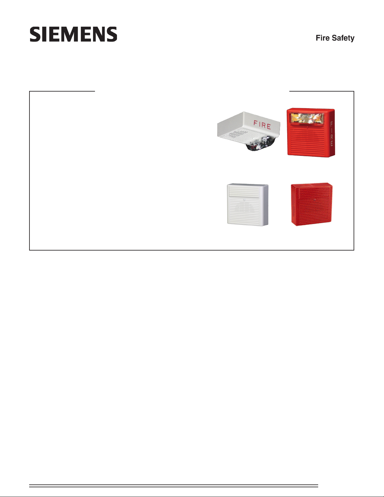
AS Audible Strobe Appliances and AH Audibles
ENGINEER AND ARCHITECT SPECIFICATIONS
• ULlisted.ULC,CSFM,andFMpending.
• ADA/NFPA/UFC/ANSICompliant
• WallmountmodelsareavailablewithFieldSelectableCandela
Settingsof15/30/75/110cdor135/185cd(Multi-Candelamodels)
• Ceilingmountmodelsareavailablewitheldselectablecandela
settingsof15/30/75/95cdor115/177cd(Multi-
candelaceilingmodels)
• SelectableContinuousHornorTemporal(Code3).
• 3SelectabledBAsettings(99,95and90dBA)inbothtones
• Weatherproofmodelsareavailableforoutdooruse
• StrobescanbesynchronizedusingtheSiemensDSCsync
modules,FS-250panel,XLSpanel,orPAD-3powersupplywith
built-insyncprotocol.
AS-MC-CW AS-MC-R
• FastinstallationwithIN/OUTscrewterminalsusing#12to#18
AWGwires
Description
The Siemens 2-wire Series AS Audible Strobe Appliances and Series AH Audibles offer more features with
low current draw.
Strobe options for wall mount models include the Sie-
mens MC multi-candela wall strobes with eld selectable
candela settings of 15/30/75/110cd, or the high intensity
HMC strobe with eld selectable 135/185cd.
Ceiling mount models incorporate Siemens MC multi-
candela ceiling strobe with eld selectable settings of
15/30/75/95cd or the high intensity HMC strobe with eld
selectable settings of 115/177cd.
The audible provides a selectable choice of either a continuous horn or temporal pattern (Code 3) when constant
voltage from a Fire Alarm Panel (FACP) is applied. Each
tone has 3 dBA settings from which to choose.
When used with the Siemens DSC sync modules,
FS-250 panel, XLS panel, or PAD-3 power supply with
built-in sync protocol, synchronization of the continuous
horn tone provides the temporal (code 3) tone (mandated by NFPA 72) simultaneously for all audible appliances. This ensures a distinct temporal (code 3) pattern
when 2 or more audibles are within hearing distance. If
not synchronized the temporal sound could overlap and
not be distinctive. At the same time the strobes will be
synchronized. This provides the ability to comply with
ADA guidelines concerning photosensitive epilepsy and
the NFPA standards when installing
AH-W
2 or more visual appliances within the eld of view all of
this plus the ability to silence the audible is achieved by
using only 2 wires.
AH-R
Engineering Specications
The notication appliances shall be Siemens Series
AS Audible Strobe appliances and Series AH Audible
appliances or approved equals. The Series AS Audible
be listed for UL Standard 1971 (Emergency Devices for
the Hearing-Impaired) for Indoor Fire Protection Service.
The Series AH Audible shall be UL Listed under Standard 464 (Fire Protective Signaling). Both shall meet
the requirements of FCC Part 15 Class B. All inputs
shall be compatible with standard reverse polarity supervision of circuit wiring by a Fire Alarm Control Panel
(FACP).
The audible portion of the appliance shall have a mini-
mum of three (3) eld selectable settings for dBA levels
and shall have a choice of continuous or temporal (Code
3) audible outputs.
The strobe portion of the appliance shall produce a ash
rate of one (1) ash per second over the Regulated
Voltage Range and shall incorporate a Xenon ashtube
enclosed in a rugged Lexan® lens. The Series AS
shall be of low current design. Where Multi-Candela
CATALOG SHEET
2578
Page 2

appliances are specied, the strobe intensity shall have
eld selectable settings and shall be rated per UL Standard 1971 at 15/30/75/110 or 135/185 candela for wall
mount and 15/30/75/95 or 115/177 candela for ceiling
mount. The selector switch for selecting the candela
shall be tamper resistant.
When synchronization is required, the appliance shall
be synchronized using the Siemens DSC sync modules,
FS-250 panel, XLS panel, or PAD-3 power supply with
built-in sync protocol. The strobes shall not drift out of
synchronization at any time during operation. If the sync
module or Power Supply fails to operate, (i.e., contacts
remain closed), the strobe shall revert to a non-synchro-
that shall allow mounting to a single-gang, double-gang,
4-inch square, 100mm European type backboxes, or the
SHBBS Surface Backbox.
All notication appliances shall be listed for Special Applications.
• Strobes are designed to ash at 1 ash per second
minimum over their “Regulated Input Voltage Range”.
Note that NFPA-72 species a ash rate of 1 to 2
ashes per second and ADA Guidelines specify a ash
rate of 1 to 3 ashes per second.
• All candela ratings represent minimum effective Strobe
intensity based on UL Standard 1971.
nized ash-rate. The appliance shall also be designed
so that the audible signal may be silenced while maintaining strobe activation when used with Siemens synchronization.
The Series AS Audible Strobe and Series AH Audible
shall incorporate a Patented Universal Mounting Plate
Technical Information
For complete technical information, please consult the
relevant installation sheets as well as the Siemens
Compatibility Guide.
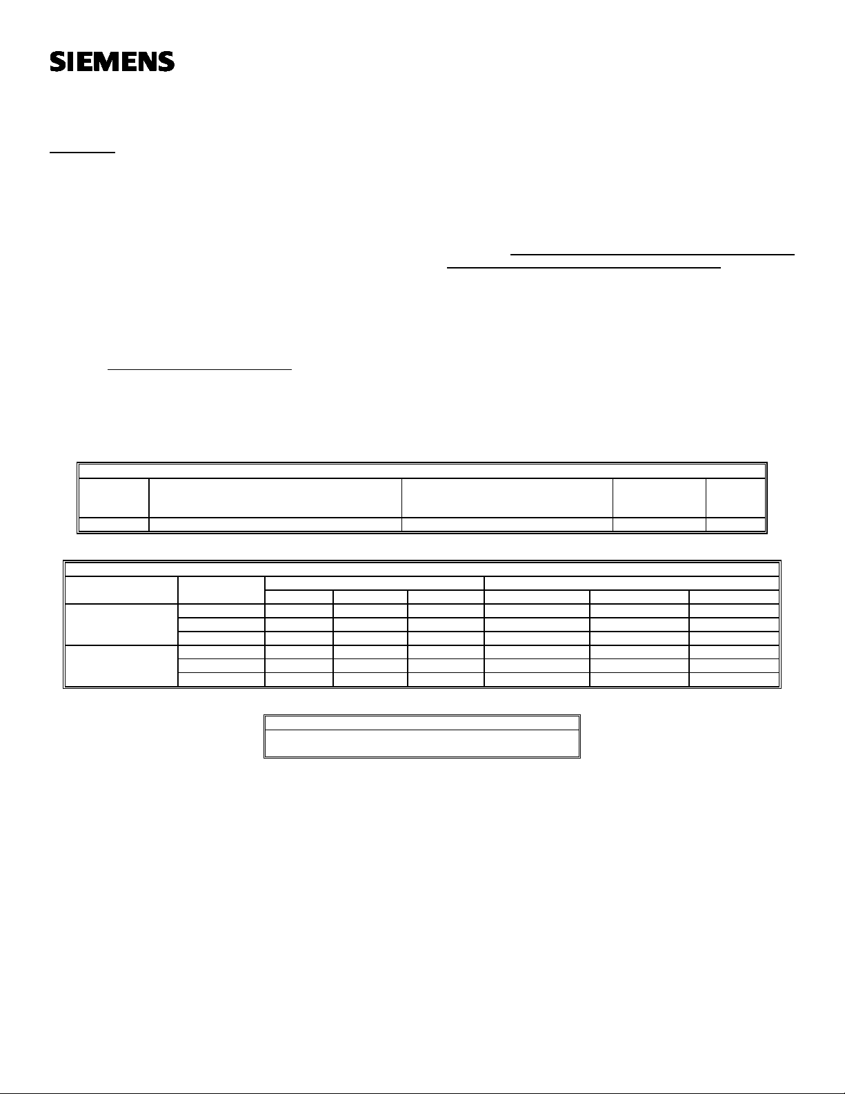
Ordering Information / Mounting Requirements / Approvals
Model
Number
AS-MC-R 500-636010 X - A,B,D,E,F,G,J,N,R,X X # # #
AS-MC-W 500-636011 X - A,B,D,E,F,G,J,N,R,X X # # #
AS-HMC-R 500-636012 X - A,B,D,E,F,G,J,N,R,X X # # #
AS-HMC-W 500-636013 X - A,B,D,E,F,G,J,N,R,X X # # #
AS-MC-CR 500-636006 - X A,B,D,E,F,G,J,N,R,X X # # #
AS-MC-CW 500-636007 - X A,B,D,E,F,G,J,N,R,X X # # #
AS-HMC-CR 500-636008 - X A,B,D,E,F,G,J,N,R,X X # # #
AS-HMC-CW 500-636009 - X A,B,D,E,F,G,J,N,R,X X # # #
AS-75-R-WP 500-636016 X - I X # # #
AS-75-CR-WP 500-636015 - X I X # # #
AH-R 500-636003 X X A,B,D,E,F,G,J,N,R,X X # # #
AH-W 500-636004 X X A,B,D,E,F,G,J,N,R,X X # # #
AH-R-WP 500-636005 X X K X # # #
Order Code
Wall
Mount
Ceiling
Mount
Mounting Options**
Agency Approvals
UL ULC CSFM FM
X = listed/approved # = pending * = Refer to Data Sheet #2585 for mounting options.
WARNING: PLEASE READ THESE SPECIFICATIONS AND INSTALLATION INSTRUCTIONS CAREFULLY BEFORE
USING, SPECIFYING OR APPLYING THIS PRODUCT. FAILURE TO COMPLY WITH ANY OF THESE INSTRUCTIONS,
CAUTIONS AND WARNINGS COULD RESULT IN IMPROPER APPLICATION, INSTALLATION AND/OR OPERATION
OF THESE PRODUCTS IN AN EMERGENCY SITUATION, WHICH COULD RESULT IN PROPERTY DAMAGE, AND
SERIOUS INJURY OR DEATH TO YOU AND/OR OTHERS.
Siemens Building Technologies
Fire Safety
Fire Safety
8 Fernwood Road
Florham Park, NJ 07932
Tel: (973) 593-2600
FAX: (973) 593-6670
Website: www.sbt.siemens.com/fis
7/07
5M
SFS-IG
Printed in U.S.A.
Fire Safety
2 Kenview Boulevard
Brampton, Ontario
Canada L6T 5E4
Tel: (905) 799-9937
FAX: (905) 799-9858
July 2007
New Issue
Page 3
MULTI-CANDELA AUDIBLE STROBE APPLIANCE
INSTALLATION INSTRUCTIONS
(WALL MOUNT VERSION)
IMPORTANT – All audible and visual signaling appliances must be
installed in accordance with all applicable national and local fire alarm
codes and any other required regulatory agencies.
Series Multi-Candela Audible Strobe Appliance (AS-MC) is the
industry’s first 2-wire horn strobe alarm appliance that provides 4
selectable candela settings (15, 30, 75, 110). Siemens Audible Strobe
Appliances provide a selectable continuous or code 3 horn tone and
non-synchronized strobe when connected directly to a Fire Alarm
Control Panel (FACP). They can also provide a synchronized code 3
(or March time) horn tone and synchronized strobe when connected to
a notification appliance circuit running the Siemens sync protocol. The
AS- MC Appliance is UL Listed under Standard 1971 for Emergency
Appliances for the Hearing Impaired and UL Standard 464 for Audible
Signal Appliances. The AS-MC is also ULC Listed under Standard
CAN/ULC-S526- 02 for Visual Signaling Appliances and Standard
CAN/ULC-S525- 99 for Audible Signaling Appliances. This appliance
is listed for wall mounting and indoor use only and is equipped with
a universal mounting plate (UMP) that can be mounted to single-gang,
double-gang, 4” backbox, 100mm European backbox or SHBBS
surface backbox (See wiring and mounting information). The AS-MC
Appliance uses a xenon flashtube with solid state circuitry enclosed in
SPECIFICATIONS:
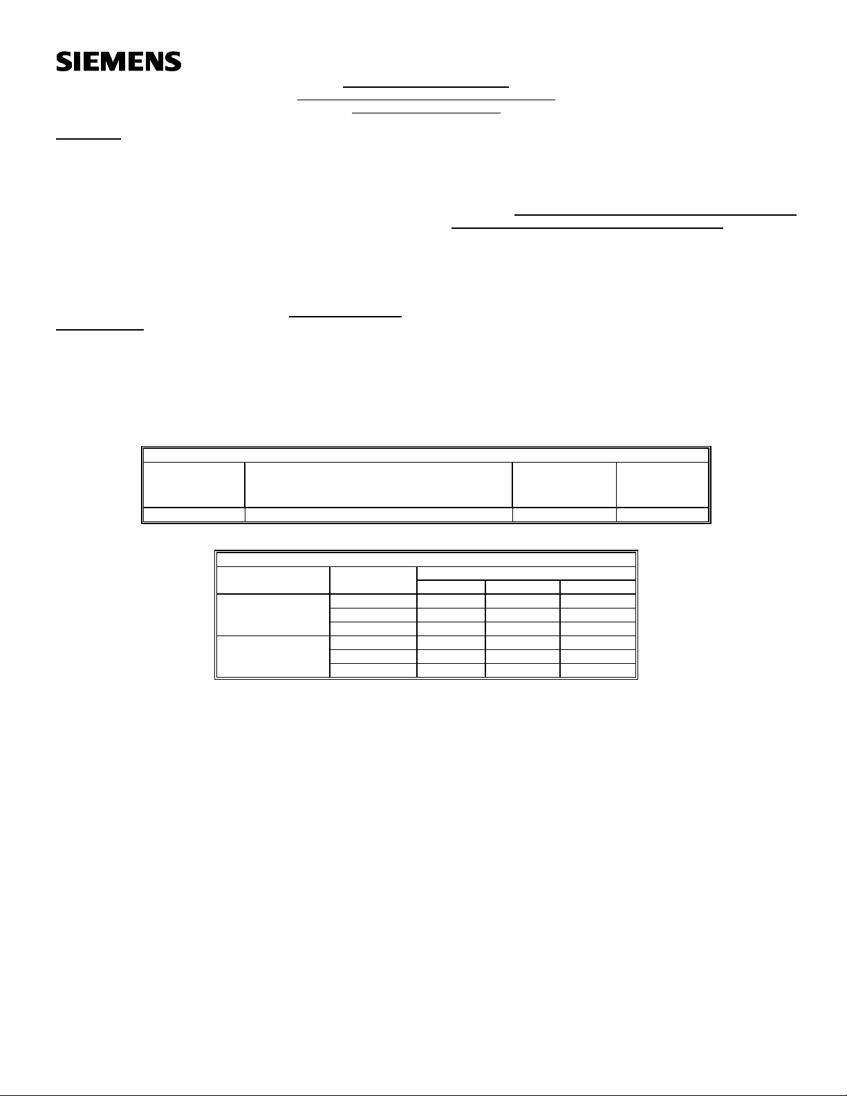
Table 1: UL/ULC Ratings
Operating Voltage (Special Application)
Model* Candela Options
Per UL 1971/464
(VDC/VRMS)
AS-MC 16.0-33.0 20.0-31.0 15/30/75/110 A,B,C,D
*Available in red and white.
a polycarbonate lens to provide maximum visibility and reliability for
effective visible signaling.
The AS-MC Appliance can be field set to provide either high (HI) dBA,
medium (MED) dBA or low (LO) dBA sound output.
NOTE: The Code 3 temporal pattern (1/2 second on, 1/2 second off,
1/2 second on, 1/2 second off, 1/2 second on, 1-1/2 off and repeat) is
specified by ANSI and NFPA 72 for standard emergency evacuation
signaling. The Code 3 Horn should be used only for fire
evacuation signaling and not for any other purpose.
This model is designed for use with either filtered DC (VDC) or
unfiltered full-wave-rectified (VRMS) input voltage. All inputs are
polarized for compatibility with standard reverse polarity supervision of
circuit wiring by an FACP.
NOTE: All Canadian installations should be in accordance with the
Canadian Standard for the Installation of Fire Alarm Systems -
CAN/ULC-S524- 01 and Canadian Electrical Code, Part 1. Final
acceptance is subject to authority having jurisdiction (AHJ).
NOTE: Refer to P/N 315-096363 for the maximum number of
appliances on a single notification appliance circuit.
Voltage Range Per
Strobe Mounting
CAN/ULC-S526- 02/S525-99
(VDC/VRMS) (cd)
Table 2: dBA Sound Output
Description Volume Reverberant Per UL 464 Anechoic dBA Per CAN/ULC-S525-99 at 10 Feet
16.0VDC 24.0VDC 33.0VDC 20.0VDC 24.0VDC 31.0VDC
Low 80 83 86 88 90 91
Continuous Horn Medium 85 88 91 93 95 97
High 88 91 93 97 99 100
Low 75 79 82 88 90 91
Code 3 Horn Medium 80 84 86 93 95 97
(or March Time)** High 84 87 90 97 99 100
**Available in sync mode only.
Table 2A: ULC Directional Characteristics
-3 dBA: 48 degrees left, 41 degrees right
-6 dBA: 50 degrees left, 58 degrees right
NOTES:
1. Strobe will produce 1 flash per second over the Input Voltage range.
2. This strobe/horn model meets the required light distribution patterns defined in UL 1971 and ULC-S526-02.
3. This model is UL/ULC Listed for indoor use with a temperature range of +32F to +120F (0C to +49C) and maximum humidity of 93%, 2% RH.
The effect of shipping and storage temperatures shall not adversely affect the performance of the appliance when it is stored in the original cartons
and not subjected to misuse or abuse.
When calculating the total current: Use Table 3 to determine the highest value of “RMS Current” for an individual AS Appliance then multiply the value
by the total number of AS Appliances. Be sure to add the currents for any other appliances powered by the same source and include any required
safety factors.
THESE APPLIANCES WERE TESTED TO THE VOLTAGE LIMITS OF 16.0-33.0 VOLTS FOR 24V MODELS USING FILTERED DC OR
UNFILTERED FULL-WAVE-RECTIFIED VOLTAGE. DO NOT APPLY VOLTAGE OUTSIDE OF THIS RANGE.
Note: Refer to the installation instructions for the appropriate NAC to find the maximum allowed voltage drop. Use this value along with the current
draw for the appliance to determine the allowable wire resistance. The maximum wire resistance between strobes shall not exceed 35 ohms.
This appliance is not designed to be used on coded systems in which the applied voltage is cycled on and off.
Siemens Building Technologies, Inc. Siemens Building Technologies, Ltd.
8 Fernwood Road 2185 Derry Road West
Florham Park, New Jersey 07932 Mississauga Ontario L5N 7A6
P83947- 007 C Canada
Page 4
CANDELA SETTING WILL DETERMINE THE CURRENT DRAW OF THE PRODUCT.
Table 3: Current Ratings (AMPS)
Maximum RMS Current with Hi dBA Setting
Input Voltage 15cd 30cd 75cd 110cd
DC 16.0-33.0VDC 0.094 0.133 0.212 0.283
FWR 16.0-33.0VRMS 0.134 0.191 0.307 0.405
Maximum RMS Current with Med dBA Setting
Input Voltage 15cd 30cd 75cd 110cd
DC 16.0-33.0VDC 0.079 0.117 0.202 0.269
FWR 16.0-33.0VRMS 0.119 0.183 0.292 0.397
Maximum RMS Current with Low dBA Setting
Input Voltage 15cd 30cd 75cd 110cd
DC 6.0-33.0VDC 0.073 0.112 0.193 0.260
FWR 16.0-33.0VRMS 0.112 0.176 0.287 0.393
Note: These notification appliances are UL Listed as “Special Application”. They are intended to be used only with Siemens notification appliance
circuits.
WARNING: MAKE SURE THAT THE TOTAL RMS CURRENT REQUIRED BY ALL APPLIANCES THAT ARE CONNECTED TO THE SYSTEM’S
PRIMARY AND SECONDARY POWER SOURCES DO NOT EXCEED THE POWER SOURCES’ RATED CAPACITY OR THE CURRENT RATINGS
OF ANY FUSES ON THE CIRCUITS TO WHICH THESE APPLIANCES ARE WIRED. OVERLOADING POWER SOURCES OR EXCEEDING FUSE
RATINGS COULD RESULT IN LOSS OF POWER AND FAILURE TO ALERT OCCUPANTS DURING AN EMERGENCY, WHICH COULD RESULT
IN PROPERTY DAMAGE AND SERIOUS INJURY OR DEATH TO YOU AND/OR OTHERS.
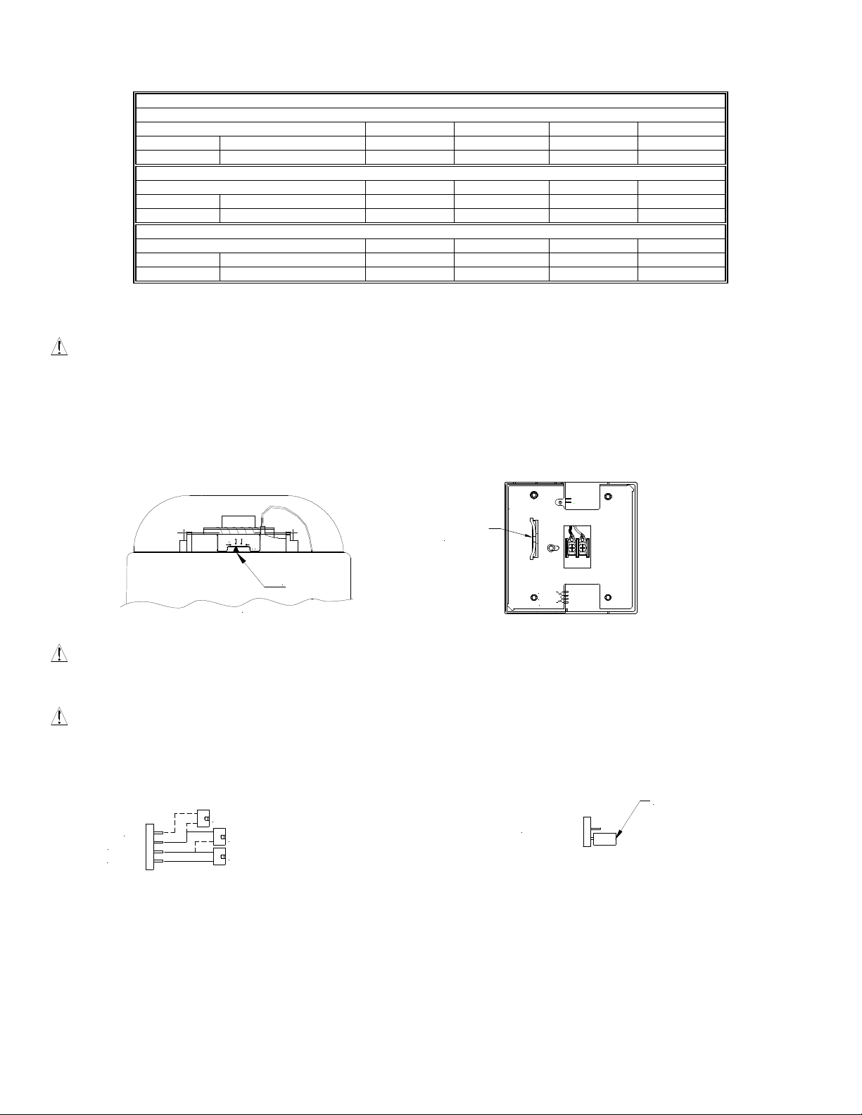
CANDELA AND SOUND OUTPUT SETTINGS:
To set the candela, slide the switch to the desired setting. The setting is indicated by the pointer and label visible on the bottom side of the lens.
Figure 1: Figure 2: Showing Location of Jumper Plug (Back View)
CODE 3
15
75 1301 0
CANDELA
SLIDE
SWITCH
CANDELA
POINTER
HI
MED
LO
BOTTOM VIEW
Factory setting is on Medium dB, Code 3 (or March Time) and 15 candela.
WARNING: THE CANDELA SELECT SWITCH MUST BE FIELD SET TO THE REQUIRED CANDELA INTENSITY BEFORE INSTALLATION.
WHEN CHANGING THE SETTING OF THE CANDELA SELECT SWITCH, MAKE CERTAIN THAT IT “CLICKS” IN PLACE. AFTER CHANGING
THE CANDELA SETTING, THE APPLIANCE MUST BE RETESTED TO VERIFY PROPER OPERATION.
WARNING: THE AUDIBLE STROBE APPLIANCES MUST BE FIELD SET TO THE DESIRED TONE AND dBA SOUND OUTPUT LEVEL
BEFORE THEY ARE INSTALLED. THIS IS DONE BY PROPERLY INSERTING JUMPER PLUGS IN ACCORDANCE WITH THESE
INSTRUCTIONS.
Figure 3: Jumper plug settings for High, Medium, Low and Code 3
(or March Time)
SHOWN SET ON HIGH dB
HI
MED
LOW
SHOWN SET ON MED dB
SHOWN SET ON LOWdB
(Use needle nose pliers to pull and properly set the jumper plugs)
Figure 4: Jumper plug setting for Continuous Horn
CODE 3
No jumper plug is needed for continuous horn setting.
However, it is recommended that the jumper plug be
retained in the unit for future use (if needed) as shown in
Figure 4.
NOTE: The AS-MC must be set for Code 3 (or March Time) when used with a synchronized notification appliance circuit (NAC).
P83947- 007 C
Sheet 2 of 4
Page 5
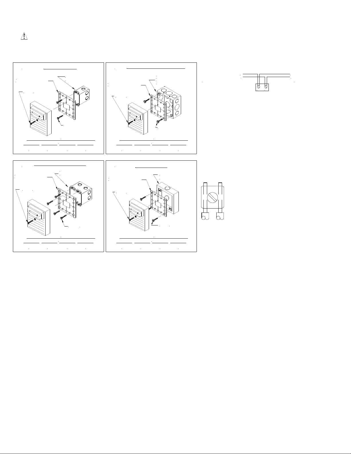
WIRING AND MOUNTING INFORMATION:
CAUTION: The following figures (A-D) show the maximum number of field wires (conductors) that can enter the backbox used with each mounting
option. If these limits are exceeded, there may be insufficient space in the backbox to accommodate the field wires and stresses from the wires could
damage the product. Check that the installed product will have sufficient clearance and wiring room prior to installing backboxes and conduit, especially
if sheathed multiconductor cable or 3/4" conduit fittings are used.
A FLUSH MOUNTING
UNIVERSAL
MOUNTING PLATE
#6-20 SCREW
MAXIMUM NUMBER OFCONDUCTORS
AWG#18 AWG#16 AWG #14 AWG #12
4 444
FLUSH OR SURFACEMOUNT
C
UNIVERSAL
MOUNTING PLATE
#6-20 SCREW
MAXIMUM NUMBER OFCONDUCTORS
AWG#18 AWG#16 AWG #14 AWG #12
4 444
STD.SINGLE-GANG
BACKBOX 2.0"DEEP
#6-32SCREWS
DOUBLE-GANGX 2-1/4"
DEEPBACKBOX
#6-32 SCREWS
FLUSH OR SURFACEMOUNTING
B
4" SQ. X 1-1/2"
DEEPBACKBOX OR
UNIVERSAL
MOUNTING PLATE
#6-20 SCREW
MAXIMUM NUMBER OFCONDUCTORS
AWG#18 AWG#16 AWG #14 AWG #12
4 444
100mmSQ.X 37.5mm
EUROPEAN BACKBOX
#8-32SCREWS
D SURFACE MOUNT
UNIVERSAL
MOUNTING PLATE
#6-20 SCREW
MAXIMUM NUMBER OFCONDUCTORS
AWG#18 AWG#16 AWG #14 AWG #12
4 444
SHBBS
SURFACE BACKBOX
#8-32SCREWS
FROMPRECEDING
APPLIANCEOR FIRE
ALARM CONTROL
PANEL (FACP)
Figure 6:
AS-MC Appliance has in -out wiring terminals
Break all in-out wire runs on supervised
Figure 5:
+
-
(+) (-)
+
TONEXTAPPLIANCE OR
-
ENDOF LINE
RESISTOR (EOLR)
that accepts two #12 to #18 American W ire Gauge
(AWG) wires at each screw terminal. Strip leads
3/8” inches for connection to screw terminals.
circuit supervision as shown in Figure 6. The
polarity shown in the wiring diagrams is for the
operation of the appliances. The polarity is
reversed by the FACP during supervision.
MOUNTING PROCEDURES:
1. This model can be flush mounted to a standard single -gang backbox (Figure A), 4” backbox (Figure B) or double-gang backbox (Figure C). They
can also be surface mounted to a 4” or 100mm backbox (Figure B), a double -gang backbox (Figure C) or a SHBBS surface backbox (Figure D).
Mounting hardware for each mounting option is supplied. For proper mounting, be sure to use the mounting screws supplied with the unit.
2. The Universal Mounting Plate (UMP) must be oriented correctly when it is mounted to the backbox. Turn the UMP so that the arrow above the
words “Horizontal Strobe” points to the top side of the UMP.
3. Conduit entrances to the backbox should be selected to provide sufficient wiring clearance for the installed product. Do not pass additional wires
(used for other than the signaling appliance) through the backbox. Such additional wires could result in insufficient wiring space for the si gnaling
appliance.
4. When terminating field wires, do not use more lead length than required. Excess lead length could result in insufficient wiring space for the
signaling appliance. Position the field wires in the backbox so that they use minimum space and produce minimum stress on the product. This is
especially important for stiff, heavy gauge wires and wires with thick insulation or sheathing.
5. Thread the 4 field wires through the opening of the UMP. Mount the UMP to backbox.
6. Connect 4 field wires to the AS-MC terminal block (polarity must be observed). Bend the 4 field wires up 90oat the connection to the terminal block.
7. Carefully push the 4 field wires into the backbox through the opening of the UMP by hand.
8. Hook the 2 slots on the inside wall of the AS-MC onto the 2 tabs of the UMP and screw the AS-MC to the UMP using the #6-20 screw supplied.
P83947- 007 C
Sheet 3 of 4
Page 6

The 110cd strobe setting is Listed for use in sleeping or non-sleeping areas when installed in accordance with appropriate NFPA Standards and AHJ.
WARNING: INSTALLATION OF THE 110 CANDELA STROBE PRODUCTS IN SLEEPING AREAS SHOULD BE WALL MOUNTED AT LEAST
24" BELOW THE CEILING AS FOLLOWS: (1) THE ON-AXIS (DIRECTLY IN FRONT OF LENS) LIGHT OUTPUT SHOULD BE DIRECTED AT THE
EYE-LIDS OF THE SLEEPING PERSON, E.G. PILLOW END OF BED, BED HEAD; (2) NO PART OF THE BED SHALL BE MORE THAN SIXTEEN
(16) FEET FROM THE STROBE NOTIFICATION APPLIANCE. INSTALLERS MUST ADVISE OWNERS AND OPERATORS OF BUILDINGS WITH
SLEEPING OCCUPANTS, E.G. HOTELS AND MOTELS, TO WARN GUESTS, RESIDENTS AND EMPLOYEES TO NOT MOVE THE BED
LOCATION TO A POSITION VIOLATING POINTS (1) AND (2) ABOVE OR SERIOUS INJURY AND/OR LOSS OF LIFE MAY OCCUR DURING A
FIRE MEERGENCY.
WARNING: A SMALL POSSIBILITY EXISTS THAT THE USE OF MULTIPLE STROBES WITHIN A PERSON'S FIELD OF VIEW, UNDER
CERTAIN CIRCUMSTANCES, MIGHT INDUCE A PHOTO-SENSITIVE RESPONSE IN PERSONS WITH EPILEPSY. STROBE REFLECTIONS IN A
GLASS OR MIRRORED SURFACE MIGHT ALSO INDUCE SUCH A RESPONSE. TO MINIMIZE THIS POSSIBLE HAZARD, IT IS STRONGLY
RECOMMENDED THAT THE STROBES INSTALLED SHOULD NOT PRESENT A COMPOSITE FLASH RATE IN THE FIELD OF VIEW WHICH
EXCEEDS FIVE (5) Hz AT THE OPERATING VOLTAGE OF THE STROBES. IT IS STRONGLY RECOMMENDED THAT THE INTENSITY AND
COMPOSITE FLASH RATE OF INSTALLED STROBES COMPLY WITH LEVELS ESTABLISHED BY APPLICABLE LAWS, STANDARDS,
REGULATIONS, CODES AND GUIDELINES.
NOTE: This equipment has been tested and found to comply with the limits for a Class B digital appliance, pursuant to Part 15 of the FCC Rules.
These limits are designed to provide reasonable protection against harmful interference in residential installation. This equipment generates, uses and
can radiate radio frequency energy and, if not installed and used in accordance with the instructions, may cause harmful interference to radio
communications. However, there is no guarantee that interference will not occur in a particular installation. If this equipment does cause harmful
interference to radio or television reception, which can be determined by turning the equipment off and on, the user is encouraged to try to correct the
interference by one or more of the following measures: 1) Reorient or relocate the receiving antenna, 2) Increase the separation between the
equipment and receiver, 3) Connect the equipment into an outlet on a circuit different from that to which the receiver is connected, and 4) Consult the
dealer or an experienced radio/TV technician for help.
P83947- 007 C
Sheet 4 of 4
Page 7
MULTI-CANDELA AUDIBLE STROBE APPLIANCE
IMPORTANT
installed in accordance with all applicable national and local fire alarm
codes and any other required regulatory agencies.
Series Audible Strobe Multi-Candela (AS-MC-C) Appliance is the
industry’s first 2-wire horn strobe alarm appliance that provides 4
selectable candela settings (15, 30, 75, 95). Siemens Audible Strobe
Appliances provide a selectable continuous or code 3 horn tone and
non-synchronized strobe when connected directly to a Fire Alarm
Control Panel (FACP). They can also provide a synchronized code 3
(or March time) horn tone and synchronized strobe connected to a
notification appliance circuit running the Siemens sync protocol. The
AS-MC-C Appliance is UL Listed under Standard 1971 for Emergency
Appliances for the Hearing Impaired and UL Standard 464 for Audible
Signal Appliances. This appliance is listed for ceiling mounting and
indoor use only
(UMP) that can be mounted to single-gang, double-gang, 4” backbox,
or 100mm European backbox (See wiring and mounting information).
The AS-MC-C Appliance uses a xenon flashtube with solid state
circuitry enclosed in a polycarbonate lens to provide maximum
visibility and reliability for effective visible signaling.
SPECIFICATIONS:
NOTES:
1. Strobe will produce 1 flash per second over the Input Voltage range.
2. This strobe/horn model meets the required light distribution patterns defined in UL 1971.
3. This model is UL Listed for indoor use with a temperature range of +32ºF to +120ºF (0ºC to +49ºC) and maximum humidity of 93% + 2% RH. The
effect of shipping and storage temperatures shall not adversely affect the performance of the appliance when it is stored in the original cartons and
not subjected to misuse or abuse.
When calculating the total current: Use Table 3 to determine the highest value of “RMS Current” for an individual AS Appliance then multiply the value
by the total number of AS Appliances. Be sure to add the currents for any other appliances powered by the same source and include any required
safety factors.
CANDELA SETTING WILL DETERMINE THE CURRENT DRAW OF THE PRODUCT.
THESE APPLIANCES WERE TESTED TO THE VOLTAGE LIMITS OF 16.0-33.0 VOLTS FOR 24V MODELS USING FILTERED DC OR
UNFILTERED FULL-WAVE-RECTIFIED VOLTAGE. DO NOT APPLY VOLTAGE OUTSIDE OF THIS RANGE.
Note: Refer to the installation instructions for the appropriate NAC to find the maximum allowed voltage drop. Use this value along with the current
draw for the appliance to determine the allowable wire resistance. The maximum wire resistance between strobes shall not exceed 35 ohms.
This appliance is not designed to be used on coded systems in which the applied voltage is cycled on and off.
Siemens Building Technologies, Inc. P84395-003 B
8 Fernwood Road Sheet 1 of 3
Florham Park, New Jersey 07932
– All audible and visual signaling appliances must be
and is equipped with a universal mounting plate
Operating Voltage (Special Application)
Model*
AS-MC-C 16.0-33.0 15/30/75/95 A,B,C,D
Description Volume Reverberant Per UL 464
16.0VDC 24.0VDC 33.0VDC
Low 80 83 86
Continuous Horn Medium 85 88 91
High 88 91 93
Low 75 79 82
Code 3 Horn Medium 80 84 86
Or March Time** High 84 87 90
INSTALLATION INSTRUCTIONS
(CEILING MOUNT VERSION)
The AS-MC-C Appliance can be field set to provide either high (HI)
dBA, medium (MED) dBA or low (LO) dBA sound output.
NOTE: The Code 3 temporal pattern (1/2 second on, 1/2 second off,
1/2 second on, 1/2 second off, 1/2 second on, 1-1/2 off and repeat) is
specified by ANSI and NFPA 72 for standard emergency evacuation
signaling. The Code 3 Horn should be used only for fire
evacuation signaling and not for any other purpose.
This model is designed for use with either filtered DC (VDC) or
unfiltered Full-Wave-Rectified (FWR) input voltage. All inputs are
polarized for compatibility with standard reverse polarity supervision of
circuit wiring by a (FACP).
Table 1: UL Ratings
Per UL 1971/464
(VDC/VRMS)
* Available in red and white.
Table 2: dBA Sound Output
**Available in sync mode only
NFPA 72/ANSI 117.1 conform to ADAAG Equivalent Facilitation
Guidelines in using fewer, higher intensity strobes within the same
protected area.
NOTE: Refer to P/N 315-096363 for the maximum number of
appliances on a single notification appliance circuit.
Strobe
Candela
(cd)
Mounting
Options
Page 8
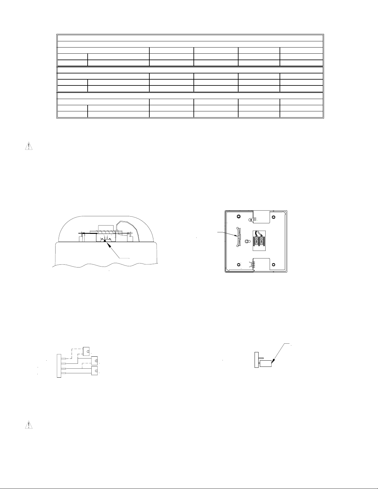
Table 3: Current Ratings (AMPS)
Maximum RMS Current with Hi dBA Setting
Voltage 15cd 30cd 75cd 95cd
DC 16.0-33.0VDC 0.101 0.147 0.235 0.303
FWR 16.0-33.0VRMS 0.144 0.202 0.324 0.424
Maximum RMS Current with Med dBA Setting
Voltage 15cd 30cd 75cd 95cd
DC 16.0-33.0VDC 0.085 0.130 0.213 0.285
FWR 16.0-33.0VRMS 0.132 0.185 0.312 0.414
Maximum RMS Current with Low dBA Setting
Voltage 15cd 30cd 75cd 95cd
DC 16.0-33.0VDC 0.079 0.120 0.210 0.279
FWR 16.0-33.0VRMS 0.122 0.180 0.308 0.409
Note: These notification appliances are UL Listed as “Special Application”. They are intended to be used only with Siemens notification appliance
circuits.
WARNING: MAKE SURE THAT THE TOTAL RMS CURRENT REQUIRED BY ALL APPLIANCES THAT ARE CONNECTED TO THE SYSTEM’S
PRIMARY AND SECONDARY POWER SOURCES DO NOT EXCEED THE POWER SOURCES’ RATED CAPACITY OR THE CURRENT RATINGS
OF ANY FUSES ON THE CIRCUITS TO WHICH THESE APPLIANCES ARE WIRED. OVERLOADING POWER SOURCES OR EXCEEDING FUSE
RATINGS COULD RESULT IN LOSS OF POWER AND FAILURE TO ALERT OCCUPANTS DURING AN EMERGENCY, WHICH COULD RESULT
IN PROPERTY DAMAGE AND SERIOUS INJURY OR DEATH TO YOU AND/OR OTHERS.
CANDELA AND SOUND OUTPUT SETTINGS:
To set the candela, slide the switch to the desired setting. The setting is indicated by the pointer and label visible on the bottom side of the lens.
Figure 1: Figure 2: Showing Location of Jumper Plug
CANDELA
15
30
75
95
SLIDE
SWITCH
CODE 3
CANDELA
POINTE R
BOTTOM VIEW
Back View
HI
MED
LO
Factory setting is on Medium dB, Code 3 (or March Time) and 15 candela.
THE CANDELA SELECT SWITCH MUST BE FIELD SET TO THE REQUIRED CANDELA INTENSITY BEFORE INSTALLATION. WHEN
CHANGING THE SETTING OF THE CANDELA SELECT SWITCH, MAKE CERTAIN THAT IT “CLICKS” IN PLACE. AFTER CHANGING THE
CANDELA SETTING, THE APPLIANCE MUST BE RETESTED TO VERIFY PROPER OPERATION
THE AUDIBLE STROBE APPLIANCES MUST BE FIELD SET TO THE DESIRED TONE AND dBA SOUND OUTPUT LEVEL BEFORE THEY ARE
INSTALLED. THIS IS DONE BY PROPERLY INSERTING JUMPER PLUGS IN ACCORDANCE WITH THESE INSTRUCTIONS.
Figure 3: Jumper plug settings for High, Medium, Low and Code 3 Figure 4: Jumper plug setting for Continuous Horn
TURN PLUG 90°
SHOWN SET ON HIGH dB
HI
MED
LOW
(Use needle nose pliers to pull and properly set the jumper plugs)
SHOWN SET ON M ED dB
SHOWN SET ON LOW dB
NOTE: The AS-MC-C must be set for Code 3 (or March Time) when used with a synchronized notification appliance circuit (NAC).
WIRING AND MOUNTING INFORMATION:
CAUTION: The following figures (A-D) show the maximum number of field wires (conductors) that can enter the backbox used with each mounting
option. If these limits are exceeded, there may be insufficient space in the backbox to accommodate the field wires and stresses from the wires could
damage the product. Check that the installed product will have sufficient clearance and wiring room prior to installing backboxes and conduit,
especially if sheathed multiconductor cable or 3/4" conduit fittings are used.
CODE 3
No jumper plug is needed for continuous horn setting.
However, it is recommended that the jumper plug be
retained in the unit for future use (if needed) as shown in
Figure 4.
Siemens Building Technologies, Inc. P84395-003 B
Sheet 2 of 3
Page 9

A
UNIVERSAL
MOUNTING PLATE
#6-20 SCREW
FLUSH MOUNTING
STD. SINGLE-GANG
BACKBOX 2.0" DEEP
#6-32 SCREWS
FLUSH OR SURFACE MOUNTING
B
UNIVERSAL
MOUNTING PLATE
SCREW
#6-20
4" SQ. X 1-1/2"
DEEP BACKBOX OR
100mm SQ. X 37.5mm
EUROPEAN BACKBOX
#8-32 SCREW S
FROM PRECEDING
APPLIANCE OR FIRE
ALARM CONTROL
PANEL (FACP)
Figure 5:
+
-
(-)
(+)
+
TO NEXT APPLIANCE OR
-
END OF LINE
RESISTOR (EOLR)
MAXIMUM NUMBER OF CONDUCTORS
AWG #18 AWG #16 AWG #14 AWG #12
4 444
FLUSH OR SURFACE MOUNT
C
UNIVERSAL
MOUNTING PLATE
#6-20 SCREW
DOUBLE-GANG X 2-1/4"
DEEP BACKBOX
MAXIMUM NUMBER OF CONDUCTORS
AWG #18 AWG #16 AWG #14 AWG #12
4 444
D
UNIVERSAL
MOUNTING PLATE
#6-20
SCREW
SURFACE MOUNT
SHBBS
SURFACE BACKBOX
Figure 6:
• AS-MC-C Appliance has in-out wiring
terminals that accepts two #12 to #18
American Wire Gauge (AWG) wires at
each screw terminal. Strip leads 3/8”
inches for connection to screw terminals.
#6-32
SCREWS
MAXIMUM NUMBER OF CONDUCTORS
AWG #18 AWG #16 AWG #14 AWG #12
4 444
MAXIMUM NUMBER OF CONDUCTORS
AWG #18 AWG #16 AWG #14 AWG #12
4 444
#8-32
SCREWS
• Break all in-out wire runs on supervised
circuit supervision as shown in Figure 6.
The polarity shown in the wiring diagrams
is for the operation of the appliances. The
polarity is reversed by the FACP during
supervision.
MOUNTING PROCEDURES:
1. This model can be flush mounted to a standard single-gang backbox (Figure A), 4” backbox (Figure B) or double-gang backbox (Figure C). They
can also be surface mounted to a 4” or 100mm backbox (Figure B), a double-gang backbox (Figure C) or a SHBBS surface backbox (Figure D).
Mounting hardware for each mounting option is supplied. For proper mounting, be sure to use the mounting screws supplied with the unit.
2. The Universal Mounting Plate (UMP) must be oriented correctly when it is mounted to the backbox. Turn the UMP so that the arrow above the
words “Horizontal Strobe” points to the top side of the UMP.
3. Conduit entrances to the backbox should be selected to provide sufficient wiring clearance for the installed product. Do not pass additional wires
(used for other than the signaling appliance) through the backbox. Such additional wires could result in insufficient wiring space for the signaling
appliance.
4. When terminating field wires, do not use more lead length than required. Excess lead length could result in insufficient wiring space for the
signaling appliance. Position the field wires in the backbox so that they use minimum space and produce minimum stress on the product. This is
especially important for stiff, heavy gauge wires and wires with thick insulation or sheathing.
5. Thread the 4 field wires through the opening of the UMP. Mount the UMP to backbox.
6. Connect 4 field wires to the AS-MC-C terminal block (polarity must be observed). Bend the 4 field wires up 90
o
at the connection to the terminal
block.
7. Carefully push the 4 field wires into the backbox through the opening of the UMP by hand.
8. Hook the 2 slots on the inside wall of the AS-MC-C onto the 2 tabs of the UMP and screw the AS-MC-C to the UMP using the #6-20 screw
supplied.
WARNING: A SMALL POSSIBILITY EXISTS THAT THE USE OF MULTIPLE STROBES WITHIN A PERSON'S FIELD OF VIEW, UNDER
CERTAIN CIRCUMSTANCES, MIGHT INDUCE A PHOTO-SENSITIVE RESPONSE IN PERSONS WITH EPILEPSY. STROBE REFLECTIONS IN A
GLASS OR MIRRORED SURFACE MIGHT ALSO INDUCE SUCH A RESPONSE. TO MINIMIZE THIS POSSIBLE HAZARD, IT IS STRONGLY
RECOMMENDED THAT THE STROBES INSTALLED SHOULD NOT PRESENT A COMPOSITE FLASH RATE IN THE FIELD OF VIEW WHICH
EXCEEDS FIVE (5) Hz AT THE OPERATING VOLTAGE OF THE STROBES. IT IS ALSO STRONGLY RECOMMENDED THAT THE INTENSITY
AND COMPOSITE FLASH RATE OF INSTALLED STROBES COMPLY WITH LEVELS ESTABLISHED BY APPLICABLE LAWS, STANDARDS,
REGULATIONS, CODES AND GUIDELINES.
The 15/30/75/95cd settings are Listed for use in sleeping or non-sleeping areas when installed in accordance with appropriate NFPA Standards and the
AHJ.
NOTE: This equipment has been tested and found to comply with the limits for a Class B digital appliance, pursuant to Part 15 of the FCC Rules.
These limits are designed to provide reasonable protection against harmful interference in residential installation. This equipment generates, uses and
can radiate radio frequency energy and, if not installed and used in accordance with the instructions, may cause harmful interference to radio
communications. However, there is no guarantee that interference will not occur in a particular installation. If this equipment does cause harmful
interference to radio or television reception, which can be determined by turning the equipment off and on, the user is encouraged to try to correct the
interference by one or more of the following measures: 1) Reorient or relocate the receiving antenna, 2) Increase the separation between the
equipment and receiver, 3) Connect the equipment into an outlet on a circuit different from that to which the receiver is connected, and 4) Consult the
dealer or an experienced radio/TV technician for help.
Siemens Building Technologies, Inc. P84395-003 B
Sheet 3 of 3
Page 10

MULTI-HIGH-CANDELA AUDIBLE STROBE APPLIANCE
IMPORTANT
installed in accordance with all applicable national and local fire alarm
codes and any other required regulatory agency.
Series Audible Strobe Multi-High-Candela (AS-HMC-C) Appliance is the
industry’s first 2-wire horn strobe alarm appliance that provides two
selectable candela settings (115, 177). Siemens Audible Strobe
Appliances provide a selectable continuous or code 3 horn tone and
non-synchronized strobe when connected directly to a Fire Alarm
Control Panel (FACP). They can also provide a synchronized code 3
(or March time) horn tone and synchronized strobe when connected to
a notification appliance circuit running the Siemens sync protocol. The
AS-HMC-C Appliance is UL Listed under Standard 1971 for Emergency
Appliances for the Hearing Impaired and UL Standard 464 for Audible
Signal Appliances. This appliance is listed for ceiling mounting and
indoor use only
(UMP) that can be mounted to single-gang, double-gang, 4” backbox,
100mm European backbox or SHBBS surface backbox (See wiring and
mounting information). The AS-HMC-C appliance uses a xenon
flashtube with solid state circuitry enclosed in a polycarbonate lens to
provide maximum visibility and reliability for effective visible signaling.
SPECIFICATIONS:
NOTES:
1. Strobe will produce 1 flash per second over the Input Voltage range.
2. This strobe/horn model meets the required light distribution patterns defined in UL 1971.
3. This model is UL Listed for indoor use with a temperature range of +32ºF to +120ºF (0ºC to +49ºC) and maximum humidity of 85% RH. The effect of
When calculating the total current: Use Table 3 to determine the highest value of “RMS Current” for an individual AS Appliance then multiply the value by
the total number of AS Appliances. Be sure to add the currents for any other appliances powered by the same source and include any required safety
factors.
THESE APPLIANCES WERE TESTED TO THE VOLTAGE LIMITS OF 16.0-33.0 VOLTS FOR 24V MODELS USING FILTERED DC OR UNFILTERED
FULL-WAVE-RECTIFIED VOLTAGE. DO NOT APPLY VOLTAGE OUTSIDE OF THIS RANGE.
Note: Refer to the installation instructions for the appropriate NAC to find the maximum allowed voltage drop. Use this value along with the current draw
for the appliance to determine the allowable wire resistance. The maximum wire resistance between strobes shall not exceed 35 ohms.
This appliance is not designed to be used on coded systems in which the applied voltage is cycled on and off.
CANDELA SETTING WILL DETERMINE THE CURRENT DRAW OF THE PRODUCT.
Siemens Building Technologies, Inc. P84448-003B
8 Fernwood Road Page 1 of 1
Florham Park, New Jersey 07932
– All audible and visual signaling appliances must be
and is equipped with a universal mounting plate
Model
AS-HMC-C* 16.0-33.0 115/177 A,B,C,D
Description Volume Reverberant Per UL 464
16.0VDC 24.0VDC 33.0VDC
Low 80 83 86
Continuous Horn Medium 85 88 91
High 88 91 93
Low 75 79 82
Code 3 Horn Medium 80 84 86
(or March Time)** High 84 87 90
shipping and storage temperatures shall not adversely affect the performance of the appliance when it is stored in the original cartons and not
subjected to misuse or abuse.
INSTALLATION INSTRUCTIONS
(CEILING MOUNT VERSION)
Table 1: UL Ratings
Operating Voltage (Special Application)
Per UL 1971
(VDC/VRMS)
* Available in red and white.
Table 2: dBA Sound Output
** Available in sync mode only.
The AS-HMC-C Appliance can be field set to provide either high (HI)
dBA, medium (MED) dBA or low (LO) dBA sound output.
This model is designed for use with either filtered DC (VDC) or
unfiltered full-wave-rectified (FWR) input voltage. All inputs are
polarized for compatibility with standard reverse polarity supervision of
circuit wiring by a FACP.
NOTE: The Code 3 temporal pattern (1/2 second on, 1/2 second off,
1/2 second on, 1/2 second off, 1/2 second on, 1-1/2 off and repeat) is
specified by ANSI and NFPA 72 for standard emergency evacuation
signaling. The Code 3 Horn should be used only for fire evacuation
signaling and not for any other purpose.
NFPA 72/ANSI 117.1 conform to ADAAG Equivalent Facilitation
Guidelines in using fewer, higher intensity strobes within the same
protected area.
NOTE: Refer to P/N 315-096363 for the maximum number of
appliances on a single notification appliance circuit. .
Strobe
Candela
(cd)
Mounting
Options
.
Page 11

Table 3: Current Ratings (AMPS)
Maximum RMS Current with Hi dBA Setting
Voltage 115cd 177cd
DC 16.0-33.0VDC 0.356 0.488
FWR 16.0-33.0VRMS 0.499 0.705
Maximum RMS Current with Med dBA Setting
Voltage 115cd 177cd
DC 16.0-33.0VDC 0.361 0.493
FWR 16.0-33.0VRMS 0.509 0.716
Maximum RMS Current with Low dBA Setting
Voltage 115cd 177cd
DC 16.0-33.0VDC 0.356 0.499
FWR 16.0-33.0VRMS 0.488 0.705
Note: These notification appliances are UL Listed as “Special Application.” They are intended to be used only with Siemens notification appliance circuits.
WARNING: MAKE SURE THAT THE TOTAL RMS CURRENT REQUIRED BY ALL APPLIANCES THAT ARE CONNECTED TO THE SYSTEM’S
PRIMARY AND SECONDARY POWER SOURCES DO NOT EXCEED THE POWER SOURCES’ RATED CAPACITY OR THE CURRENT RATINGS OF
ANY FUSES ON THE CIRCUITS TO WHICH THESE APPLIANCES ARE WIRED. OVERLOADING POWER SOURCES OR EXCEEDING FUSE
RATINGS COULD RESULT IN LOSS OF POWER AND FAILURE TO ALERT OCCUPANTS DURING AN EMERGENCY, WHICH COULD RESULT IN
PROPERTY DAMAGE AND SERIOUS INJURY OR DEATH TO YOU AND/OR OTHERS.
CANDELA AND SOUND OUTPUT SETTINGS:
To set the candela, slide the switch to the desired setting. The setting is indicated by the pointer and label visible on the bottom side of the lens.
Figure1: Figure 2: Showing Location of Jumper Plug
CODE 3
CANDELA
115
177
SLIDE
SWITCH
CANDELA
PO IN TER
BOTTOM VIEW
Back View
WARNING: THE CANDELA SELECT SWITCH MUST BE FIELD SET TO THE REQUIRED CANDELA INTENSITY BEFORE INSTALLATION.
WHEN CHANGING THE SETTING OF THE CANDELA SELECT SWITCH, MAKE CERTAIN THAT IT “CLICKS” IN PLACE. AFTER CHANGING THE
CANDELA SETTING, THE APPLIANCE MUST BE RETESTED TO VERIFY PROPER OPERATION.
WARNING: THE AUDIBLE STROBE APPLIANCES MUST BE FIELD SET TO THE DESIRED TONE AND dBA SOUND OUTPUT LEVEL BEFORE
THEY ARE INSTALLED. THIS IS DONE BY PROPERLY INSERTING JUMPER PLUGS IN ACCORDANCE WITH THESE INSTRUCTIONS.
Figure 3: Jumper plug settings for High, Medium, Low and Code 3
(or March Time)
HI
MED
LOW
(Use needle nose pliers to pull and properly set the jumper plugs)
NOTE: The AS-HMC-C must be set for Code 3 (or March Time) when used with a synchronized notification appliance circuit (NAC).
WIRING AND MOUNTING INFORMATION:
Siemens Building Technologies, Inc. P84448-003 B
Factory setting is on Medium dB, Code 3 (or March Time) and 177 candela.
SHOWN SET ON HIGH dB
SHOWN SET ON M ED dB
SHOWN SET ON LOW dB
Figure 4: Jumper plug setting for Continuous Horn
CODE 3
No jumper plug is needed for continuous horn setting.
However, it is recommended that the jumper plug be
retained in the unit for future use (if needed) as shown in
Figure 4.
HI
MED
LO
TURN PLUG 90°
Page 2 of 2
Page 12

The following figures (A-D) show the maximum number of field wires (conductors) that can enter the backbox used with each mounting option. If these
limits are exceeded, there may be insufficient space in the backbox to accommodate the field wires and stresses from the wires could damage the
product. Check that the installed product will have sufficient clearance and wiring room prior to installing backboxes and conduit, especially if sheathed
multiconductor cable or 3/4" conduit fittings are used.
A
UNIVERSAL
MOUNTING PLATE
#6-20 SCREW
FLUSH MOUNTING
STD. SINGLE-GANG
BACKBOX 2.0" DEEP
FLUSH OR SURFACE MOUNTING
B
UNIVERSAL
MOUNTING PLATE
SCREW
#6-20
4" SQ. X 1-1/2"
DEEP BACKBOX OR
100mm SQ. X 37.5mm
EUROPEAN BACKBOX
FROM PRECEDING
APPLIANCE OR FIRE
ALARM CONTROL
PANEL (FACP
+
-
Figure 5:
(-)
(+)
+
TO NEXT APPLIANCE OR
-
END OF LINE
RESISTOR (EOLR)
#6-32 SCREWS
MAXIMUM NUMBER OF CONDUCTORS
AWG #18 AWG #16 AWG #14 AWG #12
4 444
FLUSH OR SURFACE MOUNT
C
UNIVERSAL
MOUNTING PLATE
#6-20 SCR EW
DOUBLE-GANG X 2-1/4"
DEEP BACKBOX
MAXIMUM NUMBER OF CONDUCTORS
AWG #18 AWG #16 AWG #14 AWG #12
4 444
D
UNIVERSAL
MOUNTING PLATE
#6-20
SCREW
SURFACE MOUNT
#8-32 SC REWS
SHBBS
SURFACE BACKBOX
Figure 6:
• AS-HMC-C has in-out wiring terminals that
accepts two #12 to #18 American Wire Gauge
(AWG) wires at each screw terminal. Strip leads
3/8” inches for connection to screw terminals.
• Break all in-out wire runs on supervised circuit
supervision as shown in Figure 6. The polarity
shown in the wiring diagrams is for the operation
of the appliances. The polarity is reversed by the
FACP during supervision.
MAXIMUM NUMBER OF CONDUCTORS
AWG #18 AWG #16 AWG #14 AWG #12
4 444
#6-32
SCREWS
MAXIMUM NUMBER OF CONDUCTORS
AWG #18 AWG #16 AWG #14 AWG #12
4 444
#8-32
SCREWS
MOUNTING PROCEDURES:
1. This model can be flush mounted to a standard single-gang backbox (Figure A), 4” backbox (Figure B) or double-gang backbox (Figure C). They can
also be surface mounted to a 4” or 100mm backbox (Figure B), a double-gang backbox (Figure C) or a SHBBS surface backbox (Figure D).
Mounting hardware for each mounting option is supplied. For proper mounting, be sure to use the mounting screws supplied with the unit.
2. The Universal Mounting Plate (UMP) must be oriented correctly when it is mounted to the backbox. Turn the UMP so that the arrow above the words
“Horizontal Strobe” points to the top side of the UMP.
3. Conduit entrances to the backbox should be selected to provide sufficient wiring clearance for the installed product. Do not pass additional wires
(used for other than the signaling appliance) through the backbox. Such additional wires could result in insufficient wiring space for the signaling
appliance.
4. When terminating field wires, do not use more lead length than required. Excess lead length could result in insufficient wiring space for the signaling
appliance. Position the field wires in the backbox so that they use minimum space and produce minimum stress on the product. This is especially
important for stiff, heavy gauge wires and wires with thick insulation or sheathing.
5. Thread the 4 field wires through the opening of the UMP. Mount the UMP to backbox.
6. Connect 4 field wires to the AS-HMC-C terminal block (polarity must be observed). Bend the 4 field wires up 90
o
at the connection to the terminal
block.
7. Carefully push the 4 field wires into the backbox through the opening of the UMP by hand.
8. Hook the 2 slots on the inside wall of the AS-HMC-C onto the 2 tabs of the UMP and screw the unit to the UMP using the #6-20 screw supplied.
The 177cd setting is Listed for use in sleeping or non-sleeping areas when installed in accordance with appropriate NFPA Standards and the AHJ.
WARNING: A SMALL POSSIBILITY EXISTS THAT THE USE OF MULTIPLE STROBES WITHIN A PERSON'S FIELD OF VIEW, UNDER CERTAIN
CIRCUMSTANCES, MIGHT INDUCE A PHOTO-SENSITIVE RESPONSE IN PERSONS WITH EPILEPSY. STROBE REFLECTIONS IN A GLASS OR
MIRRORED SURFACE MIGHT ALSO INDUCE SUCH A RESPONSE. TO MINIMIZE THIS POSSIBLE HAZARD, SIEMENS STRONGLY
RECOMMENDS THAT THE STROBES INSTALLED SHOULD NOT PRESENT A COMPOSITE FLASH RATE IN THE FIELD OF VIEW WHICH
EXCEEDS FIVE (5) Hz AT THE OPERATING VOLTAGE OF THE STROBES. SIEMENS ALSO STRONGLY RECOMMENDS THAT THE INTENSITY
AND COMPOSITE FLASH RATE OF INSTALLED STROBES COMPLY WITH LEVELS ESTABLISHED BY APPLICABLE LAWS, STANDARDS,
REGULATIONS, CODES AND GUIDELINES.
NOTE: This equipment has been tested and found to comply with the limits for a Class B digital appliance, pursuant to Part 15 of the FCC Rules. These
limits are designed to provide reasonable protection against harmful interference in residential installation. This equipment generates, uses and can
radiate radio frequency energy and, if not installed and used in accordance with the instructions, may cause harmful interference to radio communications.
However, there is no guarantee that interference will not occur in a particular installation. If this equipment does cause harmful interference to radio or
television reception, which can be determined by turning the equipment off and on, the user is encouraged to try to correct the interference by one or more
of the following measures: 1) Reorient or relocate the receiving antenna, 2) Increase the separation between the equipment and receiver, 3) Connect
the equipment into an outlet on a circuit different from that to which the receiver is connected, and 4) Consult the dealer or an experienced radio/TV
technician for help.
Siemens Building Technologies, Inc. P84448-003 B
Page 3 of 3
Page 13

INSTALLATION INSTRUCTIONS
AUDIBLE STROBE WEATHERPROOF APPLIANCE
(WALL/CEILING MOUNT VERSION)
IMPORTANT
– All audible and visual signaling appliances must be
installed in accordance with all applicable national and local fire alarm
codes and any other required regulatory agencies.
Series AS-WP appliance is the industry’s first 2-wire horn strobe alarm
appliance that provides a selectable continuous or Code 3 horn tone
and continuous strobe when connected directly to the Fire Alarm
Control Panel (FACP), or provides a synchronized Code 3 horn tone
(or March Time) and synchronized strobe when connected to a
notification appliance circuit running the Siemens sync protocol.
Additionally, Siemens Multi-High-Candela (AS-HMC-WP and AS-HMCC-WP) appliances provide two selectable settings (135/185 or 115/177,
respectively). The AS-WP appliance is UL Listed for indoor/outdoor
use under Standard 1638 for Emergency Devices for the Hearing
Impaired (Visual Signal Appliances), UL464 for Audible Signal
Appliances and UL Standard 1971 for Emergency Appliances for the
Hearing Impaired. For outdoor application the AS-WP must be
mounted to the Weatherproof Backbox (WPBBS). The AS-WP uses a
xenon flashtube with solid state circuitry enclosed in a polycarbonate
lens to provide maximum visibility and reliability for effective visible
The AS-WP appliance can be field set to provide high (HI) dBA,
medium (MED) dBA or low (LO) dBA sound output.
The strobe is designed for use with either filtered DC (VDC) or
unfiltered full-wave-rectified (FWR) input voltage. All inputs are
polarized for compatibility with standard reverse polarity supervision of
circuit wiring by a FACP.
NOTE: The Code 3 temporal pattern (1/2 second on, 1/2 second off,
1/2 second on, 1/2 second off, 1/2 second on, 1-1/2 off and repeat) is
specified by ANSI and NFPA 72 for standard emergency evacuation
signaling. The Code 3 Horn should be used only for fire
evacuation signaling and not for any other purpose.
NFPA 72/ANSI 117.1 conform to ADAAG Equivalent Facilitation
Guidelines in using fewer, higher intensity strobes within the same
protected area.
NOTE: Refer to P/N 315-096363 for the maximum number of
appliances on a single notification appliance circuit.
signaling.
CAUTION: NOT RECOMMENDED FOR USE AT REFRIGERATOR / FREEZER DOOR ENTRANCES OR OTHER AREAS WITH PERSISTENT
CONDENSATION.
SPECIFICATIONS:
Operating Voltage
Model**
AS-75-R-WP 16.0-33.0 115 30/180 * 0.178 0.249 0.164 0.239 0.159 0.233
AS-75-CR-WP 16.0-33.0 115 30/180 * 0.178 0.249 0.164 0.239 0.159 0.233
AS-HMC-C-WP* 16.0-33.0 50/75 115/177 0.376/0.509 0.546/0.742 0.360/0.493 0.509/0.716 0.355/0.498 0.488/0.705
AS-HMC-WP* 16.0-33.0 65/90 135/185 0.376/0.509 0.546/0.742 0.360/0.493 0.509/0.716 0.355/0.498 0.488/0.705
(Special Application)
Per UL1638, UL1971 and UL464
(VDC/VRMS)
UL Rated Strobe
Candela (cd)
At -40°C
(UL1638)
Table 1: Models and Ratings
At 25°C
(UL1971)
Maximum RMS Current
w/Hi dBA (Amps)
DC FWR DC FWR DC FWR
Maximum RMS Current
w/Med dBA (Amps)
Maximum RMS Current
w/Low dBA (Amps)
*180cd is on Axis only.
**Available in red and white.
Table 2: ASWP - dBA Sound Output
Description Volume Reverberant Per UL 464 Anechoic dBA at 10 Feet
16.0VDC 24.0VDC 33.0VDC 20.0VDC 24.0VDC 31.0VDC
Low 80 83 86 88 90 91
Continuous Horn Medium 85 88 91 93 95 97
High 88 91 93 97 99 100
Low 75 79 82 88 90 91
Code 3 Horn Medium 80 84 86 93 95 97
(or March Time)*** High 84 87 90 97 99 100
***Available in sync mode only.
NOTES:
1. Strobe will produce 1 flash per second over the Input Voltage range.
2. These models meet the required light distribution patterns defined in UL 1638, UL 464 and UL 1971.
3. All models are UL Listed for indoor and outdoor use with a temperature range of -40°F to 150°F (-40°C to +66°C) and maximum humidity of 98% ±
2% RH. The effect of shipping and storage temperatures shall not adversely affect the performance of the appliance when it is stored in the original
cartons and is not subjected to misuse or abuse.
When calculating the total current: Use Table 1 to determine the highest value of “RMS Current” for an individual AS-WP Appliance then multiply the
value by the total number of AS-WP Appliances. Be sure to add the currents for any other appliances powered by the same source and include any
required safety factors.
These appliances are not designed to be used on coded systems in which the applied voltage is cycled on and off.
Siemens Building Technologies, Inc. P84820-001 B
8 Fernwood Road Sheet 1 of 3
Florham Park, New Jersey 07932
Page 14

THESE APPLIANCES WERE TESTED TO THE VOLTAGE LIMITS OF 16.0-33.0 VOLTS FOR 24V MODELS USING FILTERED DC OR UNFILTERED
FULL-WAVE-RECTIFIED VOLTAGE. DO NOT APPLY VOLTAGE OUTSIDE OF THIS RANGE.
Note: Refer to the installation instructions for the appropriate NAC to find the maximum allowed voltage drop. Use this value along with the current draw
for the appliance to determine the allowable wire resistance. The maximum wire resistance between strobes shall not exceed 35 ohms.
CANDELA SETTING WILL DETERMINE THE CURRENT DRAW OF THE PRODUCT.
Note: These notification appliances are UL Listed as “Special Application”. They are intended to be used only with Siemens notification appliance
circuits.
WARNING: MAKE SURE THAT THE TOTAL RMS CURRENT REQUIRED BY ALL APPLIANCES THAT ARE CONNECTED TO THE SYSTEM’S
PRIMARY AND SECONDARY POWER SOURCES DO NOT EXCEED THE POWER SOURCES’ RATED CAPACITY OR THE CURRENT RATINGS
OF ANY FUSES ON THE CIRCUITS TO WHICH THESE APPLIANCES ARE WIRED. OVERLOADING POWER SOURCES OR EXCEEDING FUSE
RATINGS COULD RESULT IN LOSS OF POWER AND FAILURE TO ALERT OCCUPANTS DURING AN EMERGENCY, WHICH COULD RESULT IN
PROPERTY DAMAGE AND SERIOUS INJURY OR DEATH TO YOU AND/OR OTHERS.
CANDELA AND SOUND OUTPUT (SPL) SETTINGS:
To set the candela, slide the switch to the desired setting. The setting in indicated by the pointer and label visible on the bottom of the lens.
Figure 2: Showing Location of
Figure 1: Jumper Plug
HI
MED
LO
CANDELA
POINTER
177
115
BOTTOM VIEW
CANDELA
185
135
CANDELA
POINTER
BOTTOM VIEW
SLIDE
SWITCH
CODE 3
Factory setting is on medium dB and Code 3 (or March Time). AS-HMC comes preset at 185cd. AS-HMC-C comes preset at 177cd.
WARNING: THE CANDELA SELECT SWITCH MUST BE FIELD SET TO THE REQUIRED CANDELA INTENSITY BEFORE INSTALLATION.
WHEN CHANGING THE SETTING OF THE CANDELA SELECT SWITCH, MAKE CERTAIN THAT IT “CLICKS” IN PLACE. AFTER CHANGING THE
CANDELA SETTING, THE APPLIANCE MUST BE RETESTED TO VERIFY PROPER OPERATION.
Figure 3: Jumper plug settings for High, Medium, Low and
Figure 4: Jumper plug setting for Continuous Horn
Code 3 (or March Time).
HI
MED
LOW
(Use needle nose pliers to pull and properly set the jumper plugs)
SHOWN SET ON HIGH dB
SHOWN SET ON MED dB
SHOWN SET ON LOW dB
CODE 3
No jumper plug is needed for continuous horn setting.
TURN PLUG 90°
However, it is recommended that the jumper plug be
retained in the unit for future use (if needed) as shown in
Figure 4.
NOTE: The AS-WP must be set for Code 3 (or March Time) when used on synchronized notification appliance circuit (NAC).
WIRING AND MOUNTING INFORMATION:
CAUTION: The following figure shows the maximum number of field wires (conductors) that can enter the backbox used with each mounting option.
If these limits are exceeded, there may be insufficient space in the backbox to accommodate the field wires and stresses from the wires could damage
the product. Check that the installed product will have sufficient clearance and wiring room prior to installing backboxes and conduit, especially if
sheathed multiconductor cable is used.
Figure 5: Figure 6:
FROM PRECEDING
APPLIANCE OR FIRE
ALARM CONTROL
PANEL (FACP)
+
-
(-)
(+)
+
TO NEXT APPLIANCE OR
-
END OF LINE
RESISTOR (EOLR)
• The AS-WP Appliance has in-out wiring terminals
that accepts two #12 to #18 American Wire Gauge
(AWG) wires at each screw terminal. Strip leads
3/8” inches for connection to screw terminals.
• Break all in-out wire runs on supervised circuit
supervision as shown in Figure 6. The polarity
shown in the wiring diagrams is for the operation of
the appliances. The polarity is reversed by the
FACP during supervision.
IF THE AS-WP HOUSING DOES NOT PROPERLY CONTACT THE GASKET ON THE WPBBS BACKBOX, MOISTURE MAY SEEP INTO THE ASWP WHEN USED IN A OUTDOOR APPLICATION AND THIS COULD RESULT IN IMPROPER OPERATION OF THE PRODUCT.
Siemens Building Technologies, Inc. P84820-001 B
Sheet 2 of 3
Page 15

SURFACE (INDOOR/OUTDOOR)
#6-20
SCREW
MAXIMUM NUMBER OF CONDUCTORS
AWG #18 AWG #16 AWG #14 AWG #12
4
4
THIS UNIT MUST BE MOUNTED ON A FLAT SURFACE, SO THAT THE SURFACE COVERS THE ENTIRE BACK SURFACE OF THE BACKBOX.
WPBBS
BACKBOX
WOOD
SCREWS
44
WHEN USED IN AN OUTDOOR APPLICATION OR A NEMA 3R APPLICATION, USE WEATHER PROOF RATED CONDUIT FITTING ON ALL
KNOCKOUTS OF THE BACKBOX.
1. Conduit entrances to the backbox should be selected to prov ide sufficient wiring clearance for the installed product. The knock-out opening on the
backbox is sized for a ½” conduit and matching connector. Be sure that a proper watertight conduit fitting is used to connect the backbox for
outdoor/severe environment applications. Do not pass additional wires (used for other than the signaling appliance) through the backbox. Such
additional wires could result in insufficient wiring space for the signaling appliance.
2. When terminating field wires, do not use more lead length than required. Excess lead length could result in insufficient wiring space for the
signaling appliance.
3. Connect 4 field wires to the AS-WP terminal block (polarity must be observed).
4. Bend the 4 field wires up 90° at the connection to the terminal block and carefully push the 4 field wires into the backbox by hand.
5. Carefully press the AS-WP to the backbox, verifying that the AS-WP is in contact with the gasket all the way around. It should not be
resting on the lip of the backbox.
6. Screw the AS-WP to the WPBBS using the #6-20 screw.
WARNING: A SMALL POSSIBILITY EXISTS THAT THE USE OF MULTIPLE STROBES WITHIN A PERSON'S FIELD OF VIEW, UNDER
CERTAIN CIRCUMSTANCES, MIGHT INDUCE A PHOTO-SENSITIVE RESPONSE IN PERSONS WITH EPILEPSY. STROBE REFLECTIONS IN A
GLASS OR MIRRORED SURFACE MIGHT ALSO INDUCE SUCH A RESPONSE. TO MINIMIZE THIS POSSIBLE HAZARD, SIEMENS STRONGLY
RECOMMENDS THAT THE STROBES INSTALLED SHOULD NOT PRESENT A COMPOSITE FLASH RATE IN THE FIELD OF VIEW, WHICH
EXCEEDS FIVE (5) Hz AT THE OPERATING VOLTAGE OF THE STROBES. SIEMENS ALSO STRONGLY RECOMMENDS THAT THE INTENSITY
AND COMPOSITE FLASH RATE OF INSTALLED STROBES COMPLY WITH LEVELS ESTABLISHED BY APPLICABLE LAWS, STANDARDS,
REGULATIONS, CODES AND GUIDELINES.
WARNING: REMOVAL OF THE PRINTED CIRCUIT BOARD COVER AT THE BACK OF THE MOUNTING PLATE COULD RESULT IN SEVERE
ELECTRIC SHOCK.
The 135/185cd and 177cd settings are listed for use in sleeping or non-sleeping areas when installed in accordance with appropriate NFPA Standards
and the AHJ.
NOTE: This equipment has been tested and found to comply with the limits for a Class B digital appliance, pursuant to Part 15 of the FCC Rules. These
limits are designed to provide reasonable protection against harmful interference in residential installation. This equipment generates, uses and can
radiate radio frequency energy and, if not installed and used in accordance with the instructions, may cause harmful interference to radio
communications. However, there is no guarantee that interference will not occur in a particular installation. If this equipment does cause harmful
interference to radio or television reception, which can be determined by turning the equipment off and on, the user is encouraged to try to correct the
interference by one or more of the following measures: 1) Reorient or relocate the receiving antenna, 2) Increase the separation between the
equipment and receiver, 3) Connect the equipment into an outlet on a circuit different from that to which the receiver is connected, and 4) Consult the
dealer or an experienced radio/TV technician for help.
Siemens Building Technologies, Inc. P84820-001 B
Sheet 3 of 3
Page 16

IMPORTANT
installed in accordance with all applicable national and local fire alarm
codes and any other required regulatory agencies.
Series AH Appliances provide a selectable Continuous or Code 3
Horn tone when connected directly to the Fire Alarm Control Panel
(FACP). They can also provide a synchronized code 3 or March
Time horn tone when connected to a notification appliance circuit
running the Siemens sync protocol. The AH Appliances are UL Listed
under UL Standard 464 for Audible Signal Appliances and ULC Listed
under Standard CAN/ULC-S525-99 for Audible Signaling Appliances.
They are listed for indoor use only
Universal Mounting Plate (UMP) that can be mounted to single-gang,
double-gang, 4” square backbox, 100mm European or SHBBS
surface backbox (See Mounting Options).
SPECIFICATIONS:
NOTES:
WARNING: CHECK THE MINIMUM AND MAXIMUM OUTPUT OF THE POWER SUPPLY AND STANDBY BATTERY AND SUBTRACT THE
VOLTAGE DROP FROM THE CIRCUIT WIRING RESISTANCE TO DETERMINE THE APPLIED VOLTAGE TO THE SIGNALING APPLIANCE.
FOR UL APPLICATIONS THESE APPLIANCES WERE TESTED TO THE OPERATING VOLTAGE LIMITS OF 16-33 VOLTS FOR 24V MODELS
USING FILTERED (DC) OR UNFILTERED FULL-WAVE-RECTIFIED (FWR). DO NOT APPLY 80% AND 110% OF THESE VOLTAGE VALUES
FOR SYSTEM OPERATION.
FOR ULC APPLICATIONS THESE APPLIANCES WERE TESTED TO THE OPERATING VOLTAGE LIMITS OF 20-31 VOLTS FOR 24V MODELS
USING FILTERED (DC) OR UNFILTERED FULL-WAVE-RECTIFIED (FWR). APPLY 80% AND 110% OF THESE VOLTAGE VALUES FOR
SYSTEM OPERATION.
– All audible and visual signaling appliances must be
and are equipped with a
Operating Voltage
Model*
AH 16-33 20-31 0.021 0.043 0.080 0.041 0.051 0.090
Low 80 83 86 88 90 92
Continuous Horn Medium 85 88 91 90 95 97
High 88 91 93 92 97 99
Low 75 79 82 88 90 92
Code 3 Horn or Medium 80 84 86 90 95 97
March Time* High 84 87 90 92 97 99
1. All models are UL/ULC Listed for indoor use with a temperature range of +0°C to +49°C (+32°F to +120°F) and maximum humidity of 93%
± 2% RH.
(Special Application)
Per UL 464
(VDC/VRMS)
AH
INSTALLATION INSTRUCTIONS
AUDIBLE HORN APPLIANCES
AH Appliances can be field set to provide either High (HI) dBA,
Medium (MED) dBA or Low (LO) dBA sound output. All AH models
are designed for use with either filtered DC or unfiltered Full-WaveRectified (FWR) input voltage. All inputs are polarized for
compatibility with standard reverse polarity supervision of circuit
wiring by a FACP.
NOTE: The code 3 horn incorporates the temporal pattern (1/2
second on, 1/2 second off, 1/2 second on, 1/2 second off, 1/2 second
on, 1-1/2 off and repeat) specified by ANSI/NFPA for standard
emergency evacuation signaling. The code 3 horn shall be used
only for fire evacuation signaling and not for any other purpose.
Table 1: UL/ULC Listed Models and Ratings
ULC Voltage
Range
(VDC/VRMS)
* Available in red or white.
Table 1A: ULC Current Ratings
(VDC/VRMS)
20.0 .014 .020 .035
24.0 .017 .025 .050
31.0 .021 .030 .065
Table 2: dBA Sound Output for 24VDC Models
Reverberant dBA Per UL 464 Anechoic Per CAN/ULC-S525-99 Description Volume
16.0VDC 24VDC 33.0VDC 16.0VDC 24VDC 33.0VDC
* Available in sync mode only.
Table 2A: ULC Directional Characteristics
-3 dBA: 48 degrees left, 41 degrees right
-6 dBA: 50 degrees left, 58 degrees right
Lo Med Hi Lo Med Hi
Average Current (AMPS) Model ULC Voltage
Lo Med Hi
Maximum RMS Current (AMPS)
DC FWR
Siemens Building Technologies, Inc. P83519-005 B
8 Fernwood Road Sheet 1 of 3
Florham Park, New Jersey 07932
Page 17

WARNING: MAKE SURE THAT THE TOTAL RMS CURRENT, TOTAL AVERAGE CURRENT AND TOTAL PEAK CURRENT REQUIRED BY
ALL APPLIANCES THAT ARE CONNECTED TO THE SYSTEM’S PRIMARY AND SECONDARY POWER SOURCES DO NOT EXCEED THE
POWER SOURCES’ RATED CAPACITY OR THE CURRENT RATINGS OF ANY FUSES ON THE CIRCUITS TO WHICH THESE APPLIANCES
ARE WIRED. OVERLOADING POWER SOURCES OR EXCEEDING FUSE RATINGS COULD RESULT IN LOSS OF POWER AND FAILURE TO
ALERT OCCUPANTS DURING AN EMERGENCY, WHICH COULD RESULT IN PROPERTY DAMAGE AND SERIOUS INJURY OR DEATH TO
YOU AND/OR OTHERS.
When calculating the total currents: Use Table 1 to determine the highest value of “RMS Current” for an individual AH Appliance (across the
expected operating voltage range of the AH Appliance) or use Table 1A to determine the highest value of “Rated Average Current” of an individual
AH Appliance (across the expected voltage range of the AH Appliance), then multiply these values by the total number of AH Appliances; be sure to
add the currents for any other appliances, powered by the same source and include any required safety factors.
Audible Horn appliances are not designed to be used on coded systems in which the applied voltage is cycled on and off.
WARNING: THE AUDIBLE HORN APPLIANCES MUST BE FIELD SET TO THE DESIRED TONE AND dBA SOUND OUTPUT LEVEL
BEFORE THEY ARE INSTALLED. THIS IS DONE BY PROPERLY INSERTING A JUMPER PLUG IN ACCORDANCE WITH THESE
INSTRUCTIONS.
SOUND OUTPUT (SPL) SETTINGS:
Figure 1: Showing Location of Jumper Plug
CODE 3
Factory setting is on medium dB and code 3 (or March Time).
Figure 2: Jumper plug settings for high, medium, low and code 3
(or March Time).
SHOWN SET ON HIGH dB
SHOWN SET ON MED dB
SHOWN SET ON LOW dB
(Use needle nose pliers to pull and properly set the jumper plugs)
Note: The AH must be set for code 3 (or March Time) when used with the sync module.
* Continuous horn operation without sync module.
WIRING INFORMATION:
Figure 4:
FROM PRECEDING APPLIANCE,
FIRE ALARM CONTROL PANEL (FACP)
+
-
(+)
(-)
TO NEXT APPLIANCE OR
+
END OF LINE
-
RESISTOR (EOLR)
MOUNTING OPTIONS:
HI
MED
LO
Figure 3: Jumper plug setting for Continuous Horn.
CODE 3
CONTIUOUS HORN
*
No jumper plug is needed for continuous horn setting.
TURN PLUG 90°
However, it is recommended that the jumper plug be retained
in the unit for future use (if needed) as shown in Figure 3.
Figure 5:
1. AH Appliances have in-out wiring terminals
that accepts two #12 to 18 American Wire
Gauge (AWG) wires at each screw terminal.
Strip leads 3/8” inches for connection to
screw terminals.
2. Break all in-out wire runs on supervised
circuit to assure supervision as shown in
Figure 5. The polarity shown in the wiring
diagrams are for the operation of the
appliances. The polarity is reversed by the
FACP during supervision.
Siemens Building Technologies, Inc. P83519-005 B
Sheet 2 of 3
Page 18

A
UNIVERSAL
MOUNTING PLATE
#6-20 SCREWS
FLUSH MOUNTING
STD. SINGLE-GANG
BACKBOX 2.0" DEEP
FLUSH OR SURFACE MOUNT
B
UNIVERSAL
MOUNTING PLATE
#6-20 SCREWS
4" SQ. X 1-1/2"
DEEP BACKBOX OR
100mm SQ. X 37.5mm
EUROPEAN BACKBOX
C
UNIVERSAL
MOUNTING PLATE
#6-20 SCREWS
FLUSH MOUNTING
STD. DOUBLE-GANG
BACKBOX 2-1/4" DEEP
D
UNIVERSAL
MOUNTING PLATE
#6-20 SCREWS
SURFACE MOUNT
SHBBS
SURFACE BACKBOX
MAXIMUM NUMBER OF CONDUCTORS
AWG #18 AWG #16 AWG #14 AWG #12
4 444
#6-32 SCREWS
MAXIMUM NUMBER OF CONDUCTORS
AWG #18 AWG #16 AWG #14 AWG #12
4 444
#8-32 SCREWS
#6-32 SCREWS
MAXIMUM NUMBER OF CONDUCTORS
AWG #18 AWG #16 AWG #14 AWG #12
4 444
#8-32 SCREWS
MAXIMUM NUMBER OF CONDUCTORS
AWG #18 AWG #16 AWG #14 AWG #12
4 444
MOUNTING PROCEDURES:
Use this mounting procedure to position the field wires in the backbox so that they use minimum space and produce minimum stress on the product.
This is especially important for stiff, heavy gauge wires and wires with thick insulation or sheathing.
NOTE: The Universal Mounting Plate (UMP) must be oriented correctly when it is mounted to the backbox Turn the UMP so that the arrow above the
words “Horizontal Strobe” points to the top side of the UMP.
1. Thread the 4 field wires through the opening of the UMP.
2. Mount the UMP to backbox.
3. Connect 4 field wires to the AH terminal block (polarity must be observed).
4. Bend the 4 field wires up 90
o
at the connection to the terminal block.
5. Carefully push the 4 field wires into the backbox through the opening of the UMP by hand.
6. Hook the 2 slots on the inside wall of the AH onto the 2 tabs of the UMP and screw the AH to the UMP using the #6-20 screw supplied.
MOUNTING NOTES:
Check that the installed product will have sufficient clearance and wiring room prior to installing backboxes and conduit, especially if sheathed
multiconductor cable or 3/4" conduit fittings are used.
1. All models can be flush mounted to a standard single-gang backbox (Figure A), 4” square backbox (Figure B) or double-gang backbox
(Figure C). They can also be surface mounted to a 4” square or 100mm backbox (Figure B), a double-gang backbox (Figure C) or a SHBBS
surface backbox (Figure D).
2. All models are equipped with a Universal Mounting Plate (UMP).
3. Mounting hardware for each mounting option is supplied. For proper mounting, be sure to use the mounting screws supplied with the unit.
4. Conduit entrances to the backbox should be selected to provide sufficient wiring clearance for the installed product.
5. When terminating field wires, do not use more lead length than required. Excess lead length could result in insufficient wiring space for the
signaling appliance.
6. Do not pass additional wires (used for other than the signaling appliance) through the backbox. Such additional wires could result in
insufficient wiring space for the signaling appliance.
7. The effect of shipping and storage temperatures do not adversely affect the performance of the appliances when stored in the original cartons
and are not subjected to misuse.
These appliances can produce a distinctive three pulse Temporal Pattern Fire Alarm Evacuation Signal (for total evacuation) in accordance with
NFPA 72.
NOTE: This equipment has been tested and found to comply with the limits for a Class B digital appliance, pursuant to Part 15 of the FCC Rules.
These limits are designed to provide reasonable protection against harmful interference in residential installation. This equipment generates, uses
and can radiate radio frequency energy and, if not installed and used in accordance with the instructions, may cause harmful interference to radio
communications. However, there is no guarantee that interference will not occur in a particular installation. If this equipment does cause harmful
interference to radio or television reception, which can be determined by turning the equipment off and on, the user is encouraged to try to correct the
interference by one or more of the following measures: 1) Reorient or relocate the receiving antenna, 2) Increase the separation between the
equipment and receiver, 3) Connect the equipment into an outlet on a circuit different from that to which the receiver is connected, and 4) Consult
the dealer or an experienced radio/TV technician for help.
Siemens Building Technologies, Inc. P83519-005 B
Sheet 3 of 3
Page 19

INDOOR/OUTDOOR AUDIBLE HORN APPLIANCES
INSTALLATION INSTRUCTIONS
IMPORTANT
– All audible and visual signaling appliances must be
installed in accordance with all applicable national and local fire
alarm codes and any other required regulatory agency.
Series AH-R-WP Appliances provide a selectable Continuous or
Code 3 Horn tone when connected directly to the Fire Alarm Control
Panel (FACP). They can also provide a synchronized code 3 or
march time horn tone when connected to a notification appliance
circuit running the Siemens sync protocol. The AH-R-WP
Appliances are UL Listed under UL Standard 464 for Audible Signal
Appliances. The AH-R-WP is ULC Listed under Standard
CAN/ULC-S525-99 for Audible Signaling Appliances. They are
listed for indoor and outdoor use and can be mounted to a 4”
backbox (See Mounting Options).
AH-R-WP Appliances can be field set to provide either High (HI)
dBA, Medium (MED) dBA or Low (LO) dBA sound output.
AH-R-WP models are designed for use with either filtered DC (VDC)
or unfiltered Full-Wave-Rectified (FWR) input voltage. All inputs are
polarized for compatibility with standard reverse polarity supervision
of circuit wiring by a FACP.
NOTE: The code 3 horn incorporates the temporal pattern (1/2
second on, 1/2 second off, 1/2 second on, 1/2 second off, 1/2
second on, 1-1/2 off and repeat) specified by ANSI/NFPA for
standard emergency evacuation signaling. The code 3 horn shall
be used only for fire evacuation signaling and not for any other
purpose.
SPECIFICATIONS:
Table 1: UL/ULC Listed Models and Ratings
Maximum RMS Current (AMPS)
DC FWR
Model
Operating Voltage
(Special Application)
Per UL464
(VDC/VRMS)
ULC Voltage
Range
(VDC/VRMS)
Lo Med Hi Lo Med Hi
AH-R-WP 16-33 20-31 0.023 0.049 0.090 0.046 0.057 0.096
Table 1A: ULC Current Ratings 24VDC Models
Average Current (AMPS) Model ULC Voltage
AH-R-WP
(VDC/VRMS)
20.0 .016 .022 .039
Lo Med Hi
24.0 .019 .029 .056
31.0 .023 .034 .073
Table 2: dBA Sound Output for 24VDC Models
Reverberant dBA Per UL 464 Anechoic Per CAN/ULC-S525-99 Description Volume
16.0VDC 24VDC 33.0VDC 16.0VDC 24VDC 33.0VDC
Low 80 83 86 88 90 92
Continuous Horn Medium 85 88 91 90 95 97
High 88 91 93 92 97 99
Low 75 79 82 88 90 92
Code 3 Horn or Medium 80 84 86 90 95 97
March Time* High 84 87 90 92 97 99
*Available in sync mode only.
NOTES:
1. All models are UL/ULC Listed for indoor and outdoor use with a temperature range of -31
o
F to +151oF (-35oC to 66oC) and maximum
humidity of 98% RH.
Table 2B: ULC Directional Characteristics
-3 dBA: 48 degrees left, 41 degrees right
-6 dBA: 50 degrees left, 58 degrees right
Refer to the installation instructions for the appropriate NAC to find the maximum allowed voltage drop. Use this value along with the current draw
for the appliance to determine the allowable wire resistance.
WARNING: FOR UL APPLICATIONS THESE APPLIANCES WERE TESTED TO THE OPERATING VOLTAGE LIMITS OF 16-33 VOLTS
FOR 24V MODEL USING FILTERED (DC) OR UNFILTERED FULL-WAVE-RECTIFIED (FWR). DO NOT APPLY 80% AND 110% OF THESE
VOLTAGE VALUES FOR SYSTEM OPERATION.
WARNING: FOR ULC APPLICATIONS THESE APPLIANCES WERE TESTED TO THE OPERATING VOLTAGE LIMITS OF 20-31 VOLTS
FOR 24V MODELS USING FILTERED (DC) OR UNFILTERED FULL-WAVE-RECTIFIED (FWR). APPLY 80% AND 110% OF THESE
VOLTAGE VALUES FOR SYSTEM OPERATION.
Siemens Building Technologies, Inc. P83641-005 B
8 Fernwood Road Sheet 1 of 3
Florham Park, New Jersey 07932
Page 20

WARNING: MAKE SURE THAT THE TOTAL RMS CURRENT, TOTAL AVERAGE CURRENT AND TOTAL PEAK CURRENT REQUIRED
BY ALL APPLIANCES THAT ARE CONNECTED TO THE SYSTEM’S PRIMARY AND SECONDARY POWER SOURCES DO NOT EXCEED
THE POWER SOURCES’ RATED CAPACITY OR THE CURRENT RATINGS OF ANY FUSES ON THE CIRCUITS TO WHICH THESE
APPLIANCES ARE WIRED. OVERLOADING POWER SOURCES OR EXCEEDING FUSE RATINGS COULD RESULT IN LOSS OF POWER
AND FAILURE TO ALERT OCCUPANTS DURING AN EMERGENCY, WHICH COULD RESULT IN PROPERTY DAMAGE AND SERIOUS
INJURY OR DEATH TO YOU AND/OR OTHERS.
When calculating the total currents: Use Table 1 to determine the highest value of “RMS Current” for an individual AH-R-WP Appliance (across
the expected operating voltage range of the AH-R-WP Appliance) or use Table 1A to determine the highest value of “Rated Average Current” of an
individual AH-R-WP Appliance (across the expected voltage range of the AH-R-WP Appliance), then multiply these values by the total number of
AH-R-WP Appliances; be sure to add the currents for any other appliances, powered by the same source and include any required safety factors.
Audible Horn appliances are not designed to be used on coded systems in which the applied voltage is cycled on and off.
WARNING: THE AUDIBLE HORN APPLIANCES MUST BE FIELD SET TO THE DESIRED TONE AND dBA SOUND OUTPUT LEVEL
BEFORE THEY ARE INSTALLED. THIS IS DONE BY PROPERLY INSERTING A JUMPER PLUG IN ACCORDANCE WITH THESE
INSTRUCTIONS.
SOUND OUTPUT (SPL) SETTINGS:
Figure 1: Showing Location of Jumper Plug J1 and J1.
P83511
J2 J1
J2
J1
C
H
O
M
D
E
L
+ -
AUD
3
Factory setting is on Medium dB and Code 3 (or March Time).
C
O
H
D
E
M
3
L
Figure 2: Jumper Plug Settings for High, Medium, Low dB,
Code 3 Horn (or March Time) and Continuous Horn Setting
J2 J2 J2
H
M
L
HIGH
HORN
SETTING
J1
H
M
L
MEDIUM
HORN
SETTING
H
M
L
LOW
HORN
SETTING
C
O
D
E
3 3
CODE 3 HORN
or MARCH TIME
SETTING
(Use needle nose pliers to pull and properly insert the jumper plug.)
J1
C
O
D
E
CONTINUOUS
* HORN
SETTING
No jumper plug is needed for continuous horn setting. However, it is recommended that the jumper plug be retained in the unit for future use (if
needed) as shown in Figure 2.
NOTE: The Audible Horn must be set for code 3 (or March Time) when used with the sync module.
* Continuous horn operation without sync module.
WIRING INFORMATION:
Figure 3: Figure 4:
FROM PRECEDING APPLIANCE OR
FIRE ALARM CONTROL P A NEL (FACP)
+
-
TO NEXT APPLIANCE OR
+
END OF LINE
-
RESISTOR (EOLR)
(+)
(-)
1. AH-R-WP Appliances have in-out wiring terminals that accepts two #12 to #18 American Wire Gauge (AWG) wires at each screw terminal.
Strip leads 3/8” inches for connection to screw terminals.
2. Break all in-out wire runs on supervised circuit supervision as shown in Figure 4. The polarity shown in the wiring diagrams is for the
operation of the appliances. The polarity is reversed by the FACP during supervision.
Siemens Building Technologies, Inc. P83641-005 B
Sheet 2 of 3
Page 21

MOUNTING OPTIONS:
A
SURFACE MOUN TING
APPLIANCE
#8-32 SCREWS
#10-24 SCREWS
MAXIMUM NUMBER OF CONDUCTORS
AWG #18 AWG #16 AWG #14 AWG #12
4 444
4" SQ. X 2-1/8"
DEEP BACKBOX
B
APPLIANCE
OUTDOOR MOUNTING
WEATHER RESISTANT
BACKBOX TO BE MOUNTED
ON WALL SURFACE
MAXIMUM NUMBER OF CONDUCTORS
AWG #18 AWG #16 AWG #14 AWG #12
4 444
#8-32 SCREWS
1/2" CONDUIT
ENTRANCE ON TOP
MOUNTING NOTES:
CAUTION: Check that the installed product will have sufficient clearance and wiring room prior to installing backboxes and conduit, especially
if sheathed multiconductor cable or 3/4" conduit fittings are used.
1. For weather resistant installation, use outdoor mounting option.
2. All models can be surface mounted to a 4” square by 2-1/8” deep electrical backbox (Figure A) or a weatherproof backbox (Figure B).
3. Mounting hardware for each mounting option is supplied. For proper mounting, be sure to use the mounting screws supplied with the unit.
4. Conduit entrances to the backbox should be selected to provide sufficient wiring clearance for the installed product.
5. Use care and proper techniques to position the field wires in the backbox so that they use minimum space and produce minimum stress on
the product. This is especially important for stiff heavy gauge wires with thick insulation or sheathing.
6. When terminating field wires, do not use more lead length than required. Excess lead length could result in insufficient wiring space for the
signaling appliance.
7. Do not pass additional wires (used for other than the signaling appliance) through the backbox. Such additional wires could result in
insufficient wiring space for the signaling appliance.
8. The knock-out opening on the backbox is sized for a ½” conduit and matching connector. Be sure that a proper watertight conduit fitting is
used to connect the backbox for outdoor/severe environment applications.
These appliances can produce a distinctive three pulse Temporal Pattern Fire Alarm Evacuation Signal (for total evacuation) in accordance with
NFPA 72.
NOTE: This equipment has been tested and found to comply with the limits for a Class B digital device, pursuant to Part 15 of the FCC Rules.
These limits are designed to provide reasonable protection against harmful interference in residential installation. This equipment generates, uses
and can radiate radio frequency energy and, if not installed and used in accordance with the instructions, may cause harmful interference to radio
communications. However, there is no guarantee that interference will not occur in a particular installation. If this equipment does cause harmful
interference to radio or television reception, which can be determined by turning the equipment off and on, the user is encouraged to try to correct
the interference by one or more of the following measures: 1) Reorient or relocate the receiving antenna, 2) Increase the separation between the
equipment and receiver, 3) Connect the equipment into an outlet on a circuit different from that to which the receiver is connected, and 4) Consult
the dealer or an experienced radio/TV technician for help.
Siemens Building Technologies, Inc. P83641-005 B
Sheet 3 of 3
Page 22

MULTI-HIGH-CANDELA AUDIBLE STROBE APPLIANCE
IMPORTANT
installed in accordance with all applicable national and local fire alarm
codes and any other required regulatory agency.
Series Audible Strobe Multi-High-Candela (AS-HMC) Appliance is the
industry’s first 2-wire horn strobe alarm appliance that provides two
selectable candela settings (135, 185). Siemens Audible Strobe
Appliances provide a selectable continuous or code 3 horn tone and
non-synchronized strobe when connected directly to a Fire Alarm
Control Panel (FACP). They can also provide a synchronized code 3
(or March time) horn tone and synchronized strobe when connected to
a notification appliance circuit running the Siemens sync protocol. The
AS-HMC appliance is UL Listed under Standard 1971 for Emergency
Appliances for the Hearing Impaired and UL Standard 464 for Audible
Signal Appliances. This appliance is listed for wall mounting and
indoor use only
(UMP) that can be mounted to single-gang, double-gang, 4” backbox,
100mm European backbox or SHBBS surface backbox (See wiring and
mounting information). The AS-HMC Appliance uses a xenon flashtube
with solid state circuitry enclosed in a polycarbonate lens to provide
maximum visibility and reliability for effective visible signaling.
SPECIFICATIONS:
NOTES:
1. Strobe will produce 1 flash per second over the Input Voltage range.
2. This strobe/horn model meets the required light distribution patterns defined in UL 1971.
3. This model is UL Listed for indoor use with a temperature range of +32ºF to +120ºF (0ºC to +49ºC) and maximum humidity of 85% RH. The effect of
When calculating the total current: Use Table 3 to determine the highest value of “RMS Current” for an individual AS Appliance then multiply the value by
the total number of AS Appliances. Be sure to add the currents for any other appliances powered by the same source and include any required safety
factors
THESE APPLIANCES WERE TESTED TO THE VOLTAGE LIMITS OF 16.0-33.0 VOLTS FOR 24V MODELS USING FILTERED DC OR UNFILTERED
FULL-WAVE-RECTIFIED VOLTAGE. DO NOT APPLY VOLTAGE OUTSIDE OF THIS RANGE.
Note: Refer to the installation instructions for the appropriate NAC to find the maximum allowed voltage drop. Use this value along with the current draw
for the appliance to determine the allowable wire resistance. The maximum wire resistance between strobes shall not exceed 35 ohms. .
This appliance is not designed to be used on coded systems in which the applied voltage is cycled on and off.
– All audible and visual signaling appliances must be
and is equipped with a universal mounting plate
Model*
AS-HMC 16.0-33.0 135/185 A,B,C,D
Description Volume Reverberant Per UL 464
16.0VDC 24.0VDC 33.0VDC
Low 80 83 86
Continuous Horn Medium 85 88 91
High 88 91 93
Low 75 79 82
Code 3 Horn Medium 80 84 86
(or March Time)** High 84 87 90
shipping and storage temperatures shall not adversely affect the performance of the appliance when it is stored in the original cartons and not
subjected to misuse or abuse.
INSTALLATION INSTRUCTIONS
(WALL MOUNT VERSION)
Table 1: UL Ratings
Operating Voltage (Special Application)
Per UL 1971
(VDC/VRMS)
*Available in red and white.
Table 2: dBA Sound Output
** Available in sync mode only.
The AS-HMC Appliance can be field set to provide either high (HI) dBA,
medium (MED) dBA or low (LO) dBA sound output.
This model is designed for use with either filtered DC (VDC) or
unfiltered full-wave-rectified (FWR) input voltage. All inputs are
polarized for compatibility with standard reverse polarity supervision of
circuit wiring by a FACP.
NOTE: The Code 3 temporal pattern (1/2 second on, 1/2 second off,
1/2 second on, 1/2 second off, 1/2 second on, 1-1/2 off and repeat) is
specified by ANSI and NFPA 72 for standard emergency evacuation
signaling. The Code 3 Horn should be used only for fire evacuation
signaling and not for any other purpose.
NFPA 72/ANSI 117.1 conform to ADAAG Equivalent Facilitation
Guidelines in using fewer, higher intensity strobes within the same
protected area.
NOTE: Refer to P/N 315-096363 for the maximum number of
appliances on a single notification appliance circuit.
Strobe
Candela
(cd)
Mounting
Options
WARNING: CANDELA SETTING WILL DETERMINE THE CURRENT DRAW OF THE PRODUCT.
Siemens Building Technologies, Inc. P84449-003 B
8 Fernwood Road Sheet 1 of 4
Florham Park, New Jersey 07932
Page 23

Table 3: Current Ratings (AMPS)
Maximum RMS Current with Hi dBA Setting
Voltage 135cd 185cd
DC 16.0-33.0VDC 0.356 0.488
FWR 16.0-33.0VRMS 0.499 0.705
Maximum RMS Current with Med dBA Setting
Voltage 135cd 185cd
DC 16.0-33.0VDC 0.361 0.493
FWR 16.0-33.0VRMS 0.509 0.716
Maximum RMS Current with Low dBA Setting
Voltage 135cd 185cd
DC 16.0-33.0VDC 0.356 0.499
FWR 16.0-33.0VRMS 0.488 0.705
Note: These notification appliances are UL Listed as “Special Application.” They are intended to be used only with Siemens notification appliance circuits.
WARNING: MAKE SURE THAT THE TOTAL RMS CURRENT REQUIRED BY ALL APPLIANCES THAT ARE CONNECTED TO THE SYSTEM’S
PRIMARY AND SECONDARY POWER SOURCES DO NOT EXCEED THE POWER SOURCES’ RATED CAPACITY OR THE CURRENT RATINGS OF
ANY FUSES ON THE CIRCUITS TO WHICH THESE APPLIANCES ARE WIRED. OVERLOADING POWER SOURCES OR EXCEEDING FUSE
RATINGS COULD RESULT IN LOSS OF POWER AND FAILURE TO ALERT OCCUPANTS DURING AN EMERGENCY, WHICH COULD RESULT IN
PROPERTY DAMAGE AND SERIOUS INJURY OR DEATH TO YOU AND/OR OTHERS.
CANDELA AND SOUND OUTPUT SETTINGS:
To set the candela, slide the switch to the desired setting. The setting is indicated by the pointer and label visible on the bottom side of the lens.
Figure 1: Figure 2: Showing Location of Jumper Plug
CANDELA
SLIDE
185
135
SWITCH
CODE 3
BOTTOM VIEW
Factory setting is on Medium dB, Code 3 (or March Time) and 185 candela.
CANDELA
POIN TER
HI
MED
LO
BACK VIEW
WARNING: THE AUDIBLE STROBE APPLIANCES MUST BE FIELD SET TO THE DESIRED TONE AND dBA SOUND OUTPUT LEVEL BEFORE
THEY ARE INSTALLED. THIS IS DONE BY PROPERLY INSERTING JUMPER PLUGS IN ACCORDANCE WITH THESE INSTRUCTIONS.
Figure 3: Jumper plug settings for High, Medium, Low and Code 3
Figure 4: Jumper plug setting for Continuous Horn
(or March Time)
SHOWN SET ON HIGH dB
HI
MED
LOW
SHOWN SET ON MED dB
SHOWN SET ON LOW dB
(Use needle nose pliers to pull and properly set the jumper plugs)
TURN PLUG 90°
CODE 3
No jumper plug is needed for continuous horn setting.
However, it is recommended that the jumper plug be retained in
the unit for future use (if needed) as shown in Figure 4.
NOTE: The AS-HMC must be set for Code 3 (or March Time) when used with a synchronized notification appliance circuit (NAC).
Siemens Building Technologies, Inc. P84449-003 B
Sheet 2 of 4
Page 24

WIRING AND MOUNTING INFORMATION:
CAUTION: The following figures (A-D) show the maximum number of field wires (conductors) that can enter the backbox used with each mounting
option. If these limits are exceeded, there may be insufficient space in the backbox to accommodate the field wires and stresses from the wires could
damage the product. Check that the installed product will have sufficient clearance and wiring room prior to installing backboxes and conduit, especially if
sheathed multiconductor cable or 3/4" conduit fittings are used.
A
UNIVERSAL
MOUNTING PLATE
#6-20 SCREW
FLUSH MOUNTING
STD. SINGLE-GANG
BACKBOX 2.0" DEEP
FLUSH OR SURFACE MOUNTING
B
UNIVERSAL
MOUNTING PLATE
SCREW
#6-20
4" SQ. X 1-1/2"
DEEP BACKBOX OR
100mm SQ. X 37.5mm
EUROPEAN BACKBOX
FROM PRECEDING
APPLIANCE OR SYNC
MODULE
+
-
Figure 5:
(-)
(+)
+
TO NEXT APPLIANCE OR
-
END OF LINE
RESISTOR (EOLR)
#6-32 SCREWS
MAXIMUM NUMBER OF CONDUCTORS
AWG #18 AWG #16 AWG #14 AWG #12
4 444
FLUSH OR SURFACE MOUNT
C
UNIVERSAL
MOUNTING PLATE
DOUBLE-GANG X 2-1/4"
DEEP BACKBOX
MAXIMUM NUMBER OF CONDUCTORS
AWG #18 AWG #16 AWG #14 AWG #12
4 444
D
UNIVERSAL
MOUNTING PLATE
SURFACE MOUNT
#8-32 S C RE WS
SHBBS
SURFACE BACKBOX
Figure 6:
#6-20 SCREW
#6-20
SCREW
• AS-HMC has in-out wiring terminals that
accepts two #12 to #18 American Wire Gauge
(AWG) wires at each screw terminal. Strip
leads 3/8” inches for connection to screw
terminals.
• Break all in-out wire runs on supervised circuit
supervision as shown in Figure 6. The polarity
shown in the wiring diagrams is for the
operation of the appliances. The polarity is
reversed by the FACP during supervision.
MAXIMUM NUMBER OF CONDUCTORS
AWG #18 AWG #16 AWG #14 AWG #12
4 444
#6-32
SCREWS
#8-32
MAXIMUM NUMBER OF CONDUCTORS
AWG #18 AWG #16 AWG #14 AWG #12
4 444
SCREWS
MOUNTING PROCEDURES:
1. This model can be flush mounted to a standard single-gang backbox (Figure A), 4” backbox (Figure B) or double-gang backbox (Figure C). They can
also be surface mounted to a 4” or 100mm backbox (Figure B), a double-gang backbox (Figure C) or a SHBBS surface backbox (Figure D).
Mounting hardware for each mounting option is supplied. For proper mounting, be sure to use the mounting screws supplied with the unit.
2. The Universal Mounting Plate (UMP) must be oriented correctly when it is mounted to the backbox. Turn the UMP so that the arrow above the words
“Horizontal Strobe” points to the top side of the UMP.
3. Conduit entrances to the backbox should be selected to provide sufficient wiring clearance for the installed product. Do not pass additional wires
(used for other than the signaling appliance) through the backbox. Such additional wires could result in insufficient wiring space for the signaling
appliance.
4. When terminating field wires, do not use more lead length than required. Excess lead length could result in insufficient wiring space for the signaling
appliance. Position the field wires in the backbox so that they use minimum space and produce minimum stress on the product. This is especially
important for stiff, heavy gauge wires and wires with thick insulation or sheathing.
5. Thread the 4 field wires through the opening of the UMP. Mount the UMP to backbox.
6. Connect 4 field wires to the AS-HMC terminal block (polarity must be observed). Bend the 4 field wires up 90
o
at the connection to the terminal
block.
7. Carefully push the 4 field wires into the backbox through the opening of the UMP by hand.
8. Hook the 2 slots on the inside wall of the AS-HMC onto the 2 tabs of the UMP and screw the AS-HMC to the UMP using the #6-20 screw supplied.
The 135/185cd strobe is Listed for use in sleeping or non-sleeping areas when installed in accordance with appropriate NFPA Standards and the Authority
Having Jurisdiction.
Siemens Building Technologies, Inc. P84449-003 B
Sheet 3 of 4
Page 25

WARNING: INSTALLATION OF SIEMENS 135/185 CANDELA STROBE PRODUCTS IN SLEEPING AREAS SHOULD BE WALL MOUNTED AT
LEAST 24" BELOW THE CEILING AS FOLLOWS: (1) THE ON-AXIS (DIRECTLY IN FRONT OF LENS) LIGHT OUTPUT SHOULD BE DIRECTED AT
THE EYE-LIDS OF THE SLEEPING PERSON, E.G. PILLOW END OF BED, BED HEAD; (2) NO PART OF THE BED SHALL BE MORE THAN
SIXTEEN (16) FEET FROM THE STROBE NOTIFICATION APPLIANCE. INSTALLERS MUST ADVISE OWNERS AND OPERATORS OF BUILDINGS
WITH SLEEPING OCCUPANTS, E.G. HOTELS AND MOTELS, TO WARN GUESTS, RESIDENTS AND EMPLOYEES TO NOT MOVE THE BED
LOCATION TO A POSITION VIOLATING POINTS (1) AND (2) ABOVE OR SERIOUS INJURY AND/OR LOSS OF LIFE MAY OCCUR DURING A FIRE
EMERGENCY.
WARNING: A SMALL POSSIBILITY EXISTS THAT THE USE OF MULTIPLE STROBES WITHIN A PERSON'S FIELD OF VIEW, UNDER CERTAIN
CIRCUMSTANCES, MIGHT INDUCE A PHOTO-SENSITIVE RESPONSE IN PERSONS WITH EPILEPSY. STROBE REFLECTIONS IN A GLASS OR
MIRRORED SURFACE MIGHT ALSO INDUCE SUCH A RESPONSE. TO MINIMIZE THIS POSSIBLE HAZARD, SIEMENS STRONGLY
RECOMMENDS THAT THE STROBES INSTALLED SHOULD NOT PRESENT A COMPOSITE FLASH RATE IN THE FIELD OF VIEW WHICH
EXCEEDS FIVE (5) Hz AT THE OPERATING VOLTAGE OF THE STROBES. SIEMENS ALSO STRONGLY RECOMMENDS THAT THE INTENSITY
AND COMPOSITE FLASH RATE OF INSTALLED STROBES COMPLY WITH LEVELS ESTABLISHED BY APPLICABLE LAWS, STANDARDS,
REGULATIONS, CODES AND GUIDELINES.
NOTE: This equipment has been tested and found to comply with the limits for a Class B digital appliance, pursuant to Part 15 of the FCC Rules. These
limits are designed to provide reasonable protection against harmful interference in residential installation. This equipment generates, uses and can
radiate radio frequency energy and, if not installed and used in accordance with the instructions, may cause harmful interference to radio communications.
However, there is no guarantee that interference will not occur in a particular installation. If this equipment does cause harmful interference to radio or
television reception, which can be determined by turning the equipment off and on, the user is encouraged to try to correct the interference by one or more
of the following measures: 1) Reorient or relocate the receiving antenna, 2) Increase the separation between the equipment and receiver, 3) Connect
the equipment into an outlet on a circuit different from that to which the receiver is connected, and 4) Consult the dealer or an experienced radio/TV
technician for help.
Siemens Building Technologies, Inc. P84449-003 B
Sheet 4 of 4
 Loading...