

Page 1
7SR21 & 7SR22 Argus Installation Guide
The copyright and other intellectual property rights in this document, and in any model or article produced from it
(and including any registered or unregistered design rights) are the property of Siemens Protection Devices
Limited. No part of this document shall be reproduced or modified or stored in another form, in any data retrieval
system, without the permission of Siemens Protection Devices Limited, nor shall any model or article be
reproduced from this document unless Siemens Protection Devices Limited consent.
While the information and guidance given in this document is believed to be correct, no liability shall be accepted
for any loss or damage caused by any error or omission, whether such error or omission is the result of
negligence or any other cause. Any and all such liability is disclaimed.
©2010 Siemens Protection Devices Limited Chapter 5 Page 1 of 22
7SR21 Non-Directional
7SR22 Directional
Overcurrent Relay
Document Release History
This document is issue 2010/05 The list of revisions up to and including this issue is:
2010/05 Additional Comms modules option of (RS485 + IRIG-B) and (RS232 + IRIG-B) and typographical
revisions
2008/03 First issue
2008/06 R1a Typographical revisions
2008/07 Second Issue. Software revision 2434H80011R3d-2
2009/09 Third Issue. Software revision 2435H80004/5 R4b-4
Software Revision History
2008/03 2435H800004/5R2c-2b First Release
2008/07 2434H80011R3d-2 Demand records. Optional DNP3.0 data comms.
2009/09 2435H80004/5 R4b-4 CTS-I Supervision. Undercurrent 37G & 37SEF. Vx U/O Voltage.
46BC U/C. Comms Settings. Waveform Storage Settings. Fault
Storage Settings. Energy Storage. Trip test function. Local/Remote
modes. Settings ranges extended. Protocol changes.
Page 2

7SR21 & 7SR22 Argus Installation Guide
Contents
Document Release History....................................................................................................................1
Software Revision History.....................................................................................................................1
Contents..................................................................................................................................................2
List of Figures.........................................................................................................................................3
Section 1: Installation............................................................................................................................4
1.1 Unpacking, Storage and Handling ............................................................................................4
1.2 Recommended Mounting Position............................................................................................4
1.3 Wiring ........................................................................................................................................4
1.4 Earthing.....................................................................................................................................4
1.5 Ancillary Equipment ..................................................................................................................4
Section 2: Equipment Operating Conditions.......................................................................................5
2.1 Current Transformer Circuits ....................................................................................................5
2.2 External Resistors.....................................................................................................................5
2.3 Fibre Optic Communication ......................................................................................................5
2.4 Front Cover ...............................................................................................................................5
Section 3: Dimensions and Panel Fixings...........................................................................................6
3.1 Relay Dimensions and Weight..................................................................................................6
3.2 Fixings.......................................................................................................................................7
3.2.1 Crimps ..........................................................................................................................7
3.2.2 Panel Fixings................................................................................................................7
3.2.3 Fibre Optic Connectors ................................................................................................7
Section 4: Rear Terminal Drawings......................................................................................................8
4.1 E6 Case ....................................................................................................................................8
4.2 E8 Case ..................................................................................................................................10
4.3 E8 Case ..................................................................................................................................11
Section 5: Connection/Wiring/Diagrams............................................................................................12
5.1 Wiring Diagram: 7SR21 OC/EF Relay....................................................................................12
5.2 Wiring Diagram: 7SR22 Directional OC/EF Relay..................................................................13
Section 6: Data Comms Connections................................................................................................14
6.1 Standard RS485 Connections ................................................................................................14
6.2 IRIG-B Connections ................................................................................................................14
6.3 Additional (Optional) Fibre Optic Connections........................................................................15
6.4 Additional (Optional) RS485 Connections ..............................................................................16
6.5 Additional (Optional) RS232 Connections ..............................................................................16
Section 7: Connection Diagrams........................................................................................................17
7.1 Typical Connection: 7SR22 Directional OC/EF and REF.......................................................17
7.2 Typical Connection: 7SR22 Directional OC/EF and NVD ......................................................18
7.3 Typical Connection: 7SR22 Directional OC/EF and NVD ......................................................19
7.4 Typical Connection: 7SR22 Directional OC/EF and NVD ......................................................20
7.5 Typical Connection: 7SR22 Directional OC and EF ...............................................................21
7.6 Typical Connection: 7SR22 Connected to VTs and Capacitor Cone Unit..............................22
©2010 Siemens Protection Devices Limited Chapter 5 Page 2 of 22
Page 3

7SR21 & 7SR22 Argus Installation Guide
©2010 Siemens Protection Devices Limited Chapter 5 Page 3 of 22
List of Figures
Figure 3.1-1 Overall Dimensions (mm) and panel Drilling for Size E6 Epsilon case
(Typically 4.2 kg)..................................................................................................................6
Figure 3.1-2 Overall Dimensions (mm) and Panel Drilling for Size E8 Epsilon Case
(Typically 5.3 kg)..................................................................................................................6
Figure 4.1-1 E6 Standard Comms (USB Front Port, Rear RS485) (See Note 2)....................................8
Figure 4.1-2 E6 Standard + Additional Comms (IRIG-B, 2 x F.O. (ST Connectors)) ..............................8
Figure 4.1-3 E6 Standard + Additional Comms (IRIG B + RS485) (See Note 2) ....................................9
Figure 4.1-4 E6 Standard + Additional Comms (IRIG B + RS232) ..........................................................9
Figure 4.2-1 E8 Standard Comms (USB Front Port, Rear RS485) (See Note 2)..................................10
Figure 4.2-2 E8 Standard + Additional Comms (IRIG B, 2 x F.O. (ST Connectors)).............................10
Figure 4.3-1 E8 Standard + Additional Comms (IRIG B + RS485) (See Note 2) ..................................11
Figure 4.3-2 E8 Standard + Additional Comms (IRIG B + RS232)........................................................11
Figure 5.1-1 Connection Diagram for 7SR21 Relay...............................................................................12
Figure 5.2-1 Connection Diagram for 7SR22 Relay...............................................................................13
Figure 6.1-1 RS485 Data Comms Connections Between Relays..........................................................14
Figure 6.3-1 Data Comms to Multiple Devices Using 7SG24 and F.O. Star Network...........................15
Figure 6.3-2 Data Comms to Multiple Devices Using 7SG24 and F.O. Ring Network ..........................15
Figure 6.4-1 RS485 Data Comms Connections Between Relays..........................................................16
Figure 6.5-1 RS232 Data Comms Pin Connections...............................................................................16
Figure 7.1-1 7SR22 Applied to Transformer Incomer ............................................................................17
Figure 7.2-1 7SR22 Applied to Transformer Incomer Including HV NVD Protection.............................18
Figure 7.3-1 7SR22 Applied to Feeder Including NVD Protection.........................................................19
Figure 7.4-1 7SR22 Applied to Feeder ..................................................................................................20
Figure 7.5-1 7SR22 Applied to Feeder - No Zero Sequence Voltage Source .......................................21
Figure 7.6-1 7SR22 Applied to Feeder with Capacitor Cones Fitted.....................................................22
Page 4

7SR21 & 7SR22 Argus Installation Guide
Section 1: Installation
1.1 Unpacking, Storage and Handling
On receipt remove the relay from the container in which it was received and inspect it for obvious damage. It is
recommended that the relay not be removed from its case.
If damage has been sustained a claim should be immediately be made against the carrier, also inform Siemens
Protection Devices Limited, and to the nearest Siemens agent, using the Defect Report Form in the Maintenance
section of this manual.
When not required for immediate use, the relay should be returned to its original carton and stored in a clean, dry
place.
The relay contains static sensitive devices, which are susceptible to damage due to static discharge. The relay’s
electronic circuits are protected from damage by static discharge when the relay is housed in its case.
There can be no requirement to disassemble any relay, since there are no user serviceable parts in the relay. If
any modules have been tampered with, then the guarantee will be invalidated. Siemens Protection Devices
Limited reserves the right to charge for any subsequent repairs.
1.2 Recommended Mounting Position
The relay uses a liquid crystal display (LCD) which is used in the programming and for operation. The LCD has a
vertical viewing angle of ± 30˚ and is back–lit. However, the best viewing position is at eye level, and this is
particularly important given its control features.
The relay should be mounted on the circuit breaker (or protection panel) to allow the operator the best access to
the relay functions
1.3 Wiring
The product should be wired according to the scheme requirements, with reference to the appropriate wiring
diagram. Refer to the appropriate Diagrams and Parameters document for a cross reference of wiring diagrams
and models.
1.4 Earthing
Terminal 28 of the PSU (Power Supply Unit) should be solidly earthed by a direct connection to the panel earth.
The Relay case earth stud connection should be connected to terminal 28 of the PSU.
It is normal practice to additionally 'daisy chain' together the case (safety) earths of all the Relays installed in a
panel to prevent earth current loops posing a risk to personnel.
1.5 Ancillary Equipment
The relay can be interrogated locally or remotely. For local interrogation a portable PC with suitable version of
MS Windows (2000 SP4 or XP SP2)and Reydisp Evolution™ s/w (Latest Version available 32 bit) using USB port
situated on front of the relay.
©2010 Siemens Protection Devices Limited Chapter 5 Page 4 of 22
Page 5
7SR21 & 7SR22 Argus Installation Guide
Section 2: Equipment Operating
Conditions
2.1 Current Transformer Circuits
The secondary circuit of a live CT must not be open circuited. Non-observance of this precaution can result in
injury to personnel or damage to equipment.
!
2.2 External Resistors
!
Where external resistors are fitted to relays, these may present a danger of electric shock or burns, if touched.
!
2.3 Fibre Optic Communication
Where fibre optic communication devices are fitted, these should not be viewed directly. Optical power meters
should be used to determine the operation or signal level of the device.
2.4 Front Cover
!
The front cover provides additional securing of the relay element within the case. The relay cover should be in
place during normal operating conditions.
©2010 Siemens Protection Devices Limited Chapter 5 Page 5 of 22
Page 6
7SR21 & 7SR22 Argus Installation Guide
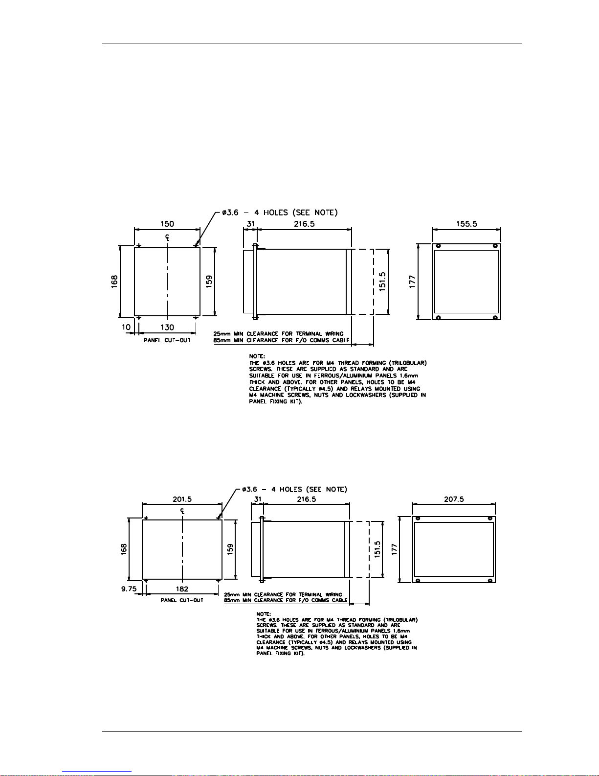
Section 3: Dimensions and Panel Fixings
3.1 Relay Dimensions and Weight
Relays are supplied in the modular size E6 or E8
The following drawing is available which gives panel cut-out and mounting details.
Figure 3.1-1 Overall Dimensions (mm) and panel Drilling for Size E6 Epsilon case (Typically 4.2 kg)
Figure 3.1-2 Overall Dimensions (mm) and Panel Drilling for Size E8 Epsilon Case (Typically 5.3 kg)
©2010 Siemens Protection Devices Limited Chapter 5 Page 6 of 22
Page 7

7SR21 & 7SR22 Argus Installation Guide
Hardware Model Net Weight kg
7SR2102 3.3
7SR2103 4.6
7SR2104 4.8
7SR2202 4.8
7SR2203 4.9
7SR2204 5.0
NB: If supplied with communication interface devices please add an additional 0.165 kg
3.2 Fixings
3.2.1 Crimps
Ring tongued crimps with 90˚ bend are recommended.
3.2.2 Panel Fixings
Typical mounting screw kit per Relay)
Consists of 4 off M4x10mm Screws
4 off M4 Nuts
4 off M4 Lock Washer
Typical rear terminal block fixing kit (1kit per terminal block fitted to relay) Consists of:
28 x M4, 8mm Screws
28 x M4 Lock Washer
3.2.3 Fibre Optic Connectors
The relay has Fibre-Optic STTM (BFOC/2.5) bayonet connectors fitted when specified.
©2010 Siemens Protection Devices Limited Chapter 5 Page 7 of 22
Page 8

7SR21 & 7SR22 Argus Installation Guide
Section 4: Rear Terminal Drawings
4.1 E6 Case
B A
Figure 4.1-1 E6 Standard Comms (USB Front Port, Rear RS485) (See Note 2)
Figure 4.1-2 E6 Standard + Additional Comms (IRIG-B, 2 x F.O. (ST Connectors))
Notes
1) Recommended terminations are pre-insulated & must be crimped using approved tooling.
2) RS485 (block ”B” terms 14, 16, 18, 20) connections to this communication facility is by screened, twisted pair
cable. On site when wiring other facilities ensure that these terminals are not obscured by other wiring runs. Cable
should be RS485 compliant.
©2010 Siemens Protection Devices Limited Chapter 5 Page 8 of 22
Page 9

7SR21 & 7SR22 Argus Installation Guide
Figure 4.1-3 E6 Standard + Additional Comms (IRIG B + RS485) (See Note 2)
Figure 4.1-4 E6 Standard + Additional Comms (IRIG B + RS232)
©2010 Siemens Protection Devices Limited Chapter 5 Page 9 of 22
Page 10

7SR21 & 7SR22 Argus Installation Guide
©2010 Siemens Protection Devices Limited Chapter 5 Page 10 of 22
BC A
4.2 E8 Case
Figure 4.2-1 E8 Standard Comms (USB Front Port, Rear RS485) (See Note 2)
Figure 4.2-2 E8 Standard + Additional Comms (IRIG B, 2 x F.O. (ST Connectors))
Notes
1) Recommended terminations are pre-insulated & must be crimped using approved tooling.
2) RS485 (block ”B” terms 14, 16, 18, 20) connections to this communication facility is by screened, twisted pair
cable. On site when wiring other facilities ensure that these terminals are not obscured by other wiring runs. Cable
should be RS485 compliant.
Page 11

7SR21 & 7SR22 Argus Installation Guide
4.3 E8 Case
Figure 4.3-1 E8 Standard + Additional Comms (IRIG B + RS485) (See Note 2)
Figure 4.3-2 E8 Standard + Additional Comms (IRIG B + RS232)
Notes
1) Recommended terminations are pre-insulated & must be crimped using approved tooling.
2) RS485 (block ”B” terms 14, 16, 18, 20) connections to this communication facility is by screened, twisted pair
cable. On site when wiring other facilities ensure that these terminals are not obscured by other wiring runs. Cable
should be RS485 compliant.
©2010 Siemens Protection Devices Limited Chapter 5 Page 11 of 22
Page 12

7SR21 & 7SR22 Argus Installation Guide
Section 5: Connection/Wiring/Diagrams
5.1 Wiring Diagram: 7SR21 OC/EF Relay
Figure 5.1-1 Connection Diagram for 7SR21 Relay
©2010 Siemens Protection Devices Limited Chapter 5 Page 12 of 22
Page 13

7SR21 & 7SR22 Argus Installation Guide
©2010 Siemens Protection Devices Limited Chapter 5 Page 13 of 22
5.2 Wiring Diagram: 7SR22 Directional OC/EF Relay
7SR22
BO 1
GND.
BI 1
+ve
+ve
-ve
-ve
I
L1
(IA)
3
1
22
24
28
2
4
BI 2
-ve
+ve
6
8
BI 3
-ve
+ve
10
12
1
2
5
6
9
10
13
14
BO 2
9
5
7
BO 3
15
11
13
BO 4
19
17
BO 5
23
21
BO 6
A
17
18
19
20
V
L1
(VA)
21
22
V
L2
(VB)
23
24
V
L3
(VC)
25
26
V
4
(VX)
27
28
BI 4
-ve
+ve
2
4
BI 5
-ve
+ve
6
8
BI 6
+ve
10
BO 7
3
1
BO 8
7
5
BO 9
11
9
BI 7
+ve
12
BI 8
+ve
14
BI 9
-ve
+ve
16
18
BI 10
20
BI 11
+ve
22
BI 12
+ve
24
BI 13
-ve
+ve
26
28
+ve
BO 10
15
13
21
19
17
BO 11
BO 12
27
25
23
BO 13
BO 14
1A
5A
1A
5A
I
L2
(IB)
1A
5A
I
L3
(IC)
1A
5A
I
4
(IG)
15
16
11
12
1A
5A
I
5
(I
SEF
)
3
4
7
8
A
Analogue
B
PSU
C
Optional
I/O
1 2
27 28
1 21 2
27 2827 28
Data
Comms
(Optional)
Rear View
Arrangement of terminals and modules
B
C
A
Screen
B
Term.
14
16
18
20
25
26
27
Shows contacts internal to relay case
assembly.
Contacts close when the relay chassis is
withdrawn from case
NOTES
BI = Binary Input
BO = Binary Output
Figure 5.2-1 Connection Diagram for 7SR22 Relay
Page 14

7SR21 & 7SR22 Argus Installation Guide
Section 6: Data Comms Connections
6.1 Standard RS485 Connections
The standard RS485 communication port is located on terminal block 2 at the rear of the relay and can be
connected using a suitable RS485 120Ω screened twisted pair cable.
The RS485 electrical connection can be used in a single or multi-drop configuration. The RS485 master must
support and use the Auto Device Enable (ADE) feature.
The last device in the connection must be terminated correctly in accordance with the master driving the
connection. A terminating resistor is fitted in each relay, when required this is connected in circuit using an
external wire loop between terminals 18 and 20 of the power supply module.
Up to 64 relays can be connected to the RS485 bus.
The RS485 data communications link with a particular relay will be broken if the relay element is withdrawn from
the case, all other relays will still communicate.
A
RS485
Screen
B
Term.
141618
20
RS 485 Twisted pair screened Cable
To
Control
System
To
Control
System
14
16
18
20
RS485 Screened
twisted pair
Rear terminals
14
16
18
14
16
18
RS485 Screened
twisted pair
Rear terminals
Ext Wire loop to
Include line
terminating Res
A
RS485
Screen
B
Term.
141618
20
A
RS485
Screen
B
Term.
141618
20
Figure 6.1-1 RS485 Data Comms Connections Between Relays
6.2 IRIG-B Connections
A BNC plug is provided on the optional additional communication interface modules to connect a co-axial cable
carrying IRIG-B time synchronisation signals. Ensure that the stub length is minimised by connecting the teeconnector directly to the rear of the relay. A suitable co-axial cable would be type RG 58 50ohms.
©2010 Siemens Protection Devices Limited Chapter 5 Page 14 of 22
Page 15

7SR21 & 7SR22 Argus Installation Guide
6.3 Additional (Optional) Fibre Optic Connections
Rear Com ports 3 and 4 comprise Fibre–Optic ST™ (BFOC/2.5) bayonet connectors-4 per product. 62.5 / 125μm
glass fibre is recommended for all distances.
When installing fibre, ensure that the fibres’ bend radii comply with the recommended minimum for the fibre usedtypically 50mm is acceptable.
Figure 6.3-1 Data Comms to Multiple Devices Using 7SG24 and F.O. Star Netwo rk
Figure 6.3-2 Data Comms to Multiple Devices Using 7SG24 and F.O. Ring Network
The F.O. data communications link with a particular relay will be broken if the relay element is withdrawn from the
case, all other relays will still communicate.
©2010 Siemens Protection Devices Limited Chapter 5 Page 15 of 22
Page 16

7SR21 & 7SR22 Argus Installation Guide
6.4 Additional (Optional) RS485 Connections
The additional (optional) RS485 communication port is located at the rear of the relay and can be connected
using a suitable RS485 120 ohm screened twisted pair cable.
The RS485 electrical connection can be used in a single or multi-drop configuration. The RS485 master must
support and use the Auto Device Enable (ADE) feature.
The last device in the connection must be terminated correctly in accordance with the master device driving the
connection. The relays are fitted with an internal terminating resistor which can be connected between the A and
B by fitting an external wire loop between terminals 18 and 20 on the power supply module.
A
RS485
Screen
B
Term.
141618
20
RS 485 Twisted pair screened Cable
To
Control
System
To
Control
System
14
16
18
20
RS485 Screened
twisted pair
Rear terminals
14
16
18
14
16
18
RS485 Screened
twisted pair
Rear terminals
Ext Wire loop to
Include line
terminating Res
A
RS485
Screen
B
Term.
141618
20
A
RS485
Screen
B
Term.
141618
20
Figure 6.4-1 RS485 Data Comms Connections Between Relays
6.5 Additional (Optional) RS232 Connections
The additional (optional) RS232 (9 pin plug) (DTE) communication port is located at the rear of the relay and can
be connected using a suitable RS232 cable.
Where there is a requirement for multi-drop RS232 connection, a suitable device to facilitate this should be
obtained.
Pin Relay Function
1 Not Connected
2 Receive Data (RXD)
3 Transmit Data (TXD)
4 Input Supply +5 V
5 Signal Ground (GND)
6 Input Supply +5 V
7 Linked to 8 (volts free)
8 Linked to 7 (volts free)
9 Output Supply +5 V 50mA
Figure 6.5-1 RS232 Data Comms Pin Connections
©2010 Siemens Protection Devices Limited Chapter 5 Page 16 of 22
Page 17

7SR21 & 7SR22 Argus Installation Guide
Section 7: Connection Diagrams
7.1 Typical Connection: 7SR22 Directional OC/EF and REF
Figure 7.1-1 7SR22 Applied to Transformer Incomer
©2010 Siemens Protection Devices Limited Chapter 5 Page 17 of 22
Page 18

7SR21 & 7SR22 Argus Installation Guide
7.2 Typical Connection: 7SR22 Directional OC/EF and NVD
Figure 7.2-1 7SR22 Applied to Transformer Incomer Including HV NVD Protection
©2010 Siemens Protection Devices Limited Chapter 5 Page 18 of 22
Page 19

7SR21 & 7SR22 Argus Installation Guide
7.3 Typical Connection: 7SR22 Directional OC/EF and NVD
S1
S2
P1
P2
L1 L2 L3
V
L
V
N
NOTES
1) CT circuits are shown connected to 1A tap – use alternative tap for 5A rated CTs.
2) CT and Earth connections are typical only.
3) Application shows use of V
4
as an NVD input.
4) Star Connected VT: Phase Voltage Config:-V
an,Vbn,Vcn
I
L1
(IA)
1
2
5
6
9
10
13
14
A
17
18
19
20
21
22
23
24
25
26
27
28
1A
5A
1A
5A
1A
5A
1A
5A
15
16
11
12
1A
5A
3
4
7
8
B
C
V
4
(VX)
V
L3
(VC)
V
L2
(VB)
V
L1
(VA)
I
L2
(IB)
I
L3
(IC)
I
4
(IG)
I
5
(I
SEF
)
Figure 7.3-1 7SR22 Applied to Feeder Including NVD Protection
©2010 Siemens Protection Devices Limited Chapter 5 Page 19 of 22
Page 20

7SR21 & 7SR22 Argus Installation Guide
7.4 Typical Connection: 7SR22 Directional OC/EF and NVD
V
L
V
N
L1 L2 L3
3Vo
S1
S2
P1
P2
I
L1
(IA)
1
2
5
6
9
10
13
14
A
17
18
19
20
21
22
23
24
25
26
27
28
1A
5A
1A
5A
1A
5A
1A
5A
15
16
11
12
1A
5A
3
4
7
8
B
C
V
4
(VX)
V
L3
(VC)
V
L2
(VB)
V
L1
(VA)
I
L2
(IB)
I
L3
(IC)
I
4
(IG)
I
5
(I
SEF
)
NOTES
1) CT circuits are shown connected to 1A tap – use alternative tap for 5A rated CTs.
2) CT and Earth connections are typical only.
3) Voltage Config:-V
ab
, Vbc, 3V
0
Figure 7.4-1 7SR22 Applied to Feeder
©2010 Siemens Protection Devices Limited Chapter 5 Page 20 of 22
Page 21

7SR21 & 7SR22 Argus Installation Guide
7.5 Typical Connection: 7SR22 Directional OC and EF
L1 L2 L3
A
C
B
S1
S2
P1
P2
I
L1
(IA)
1
2
5
6
9
10
13
14
A
17
18
19
20
21
22
23
24
25
26
27
28
1A
5A
1A
5A
1A
5A
1A
5A
15
16
11
12
1A
5A
3
4
7
8
B
C
V
4
(VX)
V
L3
(VC)
V
L2
(VB)
V
L1
(VA)
I
L2
(IB)
I
L3
(IC)
I
4
(IG)
I
5
(I
SEF
)
NOTES
1) CT circuits are shown connected to 1A tap – use alternative tap for 5A rated CTs.
2) CT and Earth connections are typical only.
3) Vee Connected VT: Phase Voltage Config:-VA,VB,VC
4) DEF elements must be NPS polarised (Vo polarising not applicable)
Figure 7.5-1 7SR22 Applied to Feeder - No Zero Sequence Voltage Source
©2010 Siemens Protection Devices Limited Chapter 5 Page 21 of 22
Page 22

7SR21 & 7SR22 Argus Installation Guide
7.6 Typical Connection: 7SR22 Connected to VTs and
Capacitor Cone Unit
L1 L2 L3
A
C
B
S1
S2
P1
P2
I
L1
(IA)
1
2
5
6
9
10
13
14
A
17
18
19
20
21
22
23
24
25
26
27
28
1A
5A
1A
5A
1A
5A
1A
5A
15
16
11
12
1A
5A
3
4
7
8
B
C
V
4
(VX)
V
L3
(VC)
V
L2
(VB)
V
L1
(VA)
I
L2
(IB)
I
L3
(IC)
I
4
(IG)
I
5
(I
SEF
)
NOTES
1) CT circuits are shown connected to 1A tap – use alternative tap for 5A rated CTs.
2) CT and Earth connections are typical only.
3) Vee Connected VT: Phase Voltage Config:-Va,Vb,Vc
4) DEF elements must be NPS polarised (Vo polarising not applicable)
5) V
4
used for NVD input
Capacitor
Cones
Adaptor
Unit
Figure 7.6-1 7SR22 Applied to Feeder with Capacitor Cones Fitted
©2010 Siemens Protection Devices Limited Chapter 5 Page 22 of 22
 Loading...