

Page 1

Arnold
ARCADIS Varic
Startup
System
SP
Start-up Instructions
08080017
Print No.:
Replaces: SPR2-310.815.01.06.02
SPR2-310.815.01.07.02
© Siemens AG
The reproduction, transmission or use
of this document or its contents is not
permitted without express written
authority. Offenders will be liable for
damages. All rights, including rights
created by patent grant or registration
of a utility model or design, are
reserved.
English
Doc. Gen. Date: 12.06
2006
Page 2

2 Revision / Disclaimer
1Revision / Disclaimer
Document revision level
The document corresponds to the version/revision level effective at the time of system
delivery. Revisions to hardcopy documentation are not automatically distributed.
Please contact your local Siemens office to order current revision levels.
Disclaimer
The installation and service of equipment described herein is to be performed by qualified
personnel who are employed by Siemens or one of its affiliates or who are otherwise
authorized by Siemens or one of its affiliates to provide such services.
Assemblers and other persons who are not employed by or otherwise directly affiliated
with or authorized by Siemens or one of its affiliates are directed to contact one of the
local offices of Siemens or one of its affiliates before attempting installation or service procedures.
ARCADIS Varic SPR2-310.815.01.07.02 Siemens AG
12.06 CS PS SP
Page 2 of 64
Medical Solutions
Page 3

Table of Contents 3
0Table of Contents
1 _______ General information______________________________________________ 5
Notes and symbols. . . . . . . . . . . . . . . . . . . . . . . . . . . . . . . . . . . . . . . . . . . . . . . . . . . . . . 5
Additionally required documents . . . . . . . . . . . . . . . . . . . . . . . . . . . . . . . . . . . . . . . . . . . 7
Safety information. . . . . . . . . . . . . . . . . . . . . . . . . . . . . . . . . . . . . . . . . . . . . . . . . . . . . . . 8
General safety information (in existing documents) . . . . . . . . . . . . . . . . . . . . . . . . . . 8
General electrical safety information. . . . . . . . . . . . . . . . . . . . . . . . . . . . . . . . . . . . . . 8
Radiation safety information . . . . . . . . . . . . . . . . . . . . . . . . . . . . . . . . . . . . . . . . . . . . 9
Systems equipped with an I.I. laser light localizer or a single tank laser light localizer 9
Systems equipped with an integrated I.I. laser light localizer . . . . . . . . . . . . . . . . . . 10
Information on the protective conductor resistance test . . . . . . . . . . . . . . . . . . . . . . 11
System leakage current measurement information . . . . . . . . . . . . . . . . . . . . . . . . . 13
Tools, aids (partially for IQ test) . . . . . . . . . . . . . . . . . . . . . . . . . . . . . . . . . . . . . . . . . . . 19
Note on the log book . . . . . . . . . . . . . . . . . . . . . . . . . . . . . . . . . . . . . . . . . . . . . . . . . . . 20
Notes on adapting the power plug to local conditions. . . . . . . . . . . . . . . . . . . . . . . . . . . 21
Power line connection information . . . . . . . . . . . . . . . . . . . . . . . . . . . . . . . . . . . . . . . . . 22
2 _______ General Start-up________________________________________________ 23
Power connection . . . . . . . . . . . . . . . . . . . . . . . . . . . . . . . . . . . . . . . . . . . . . . . . . . . . . . 23
Measuring the local line voltage . . . . . . . . . . . . . . . . . . . . . . . . . . . . . . . . . . . . . . . . 23
Adjusting the programmed system line voltage . . . . . . . . . . . . . . . . . . . . . . . . . . . . 23
Function check of the emergency stop switches . . . . . . . . . . . . . . . . . . . . . . . . . . . . . . 25
Checking the temperature indicator . . . . . . . . . . . . . . . . . . . . . . . . . . . . . . . . . . . . . . . . 26
Function checks . . . . . . . . . . . . . . . . . . . . . . . . . . . . . . . . . . . . . . . . . . . . . . . . . . . . . . . 27
Functional test of C-arm lift movement and parking brakes . . . . . . . . . . . . . . . . . . . . . . 28
3 _______ Specific system settings_________________________________________ 29
System configuration . . . . . . . . . . . . . . . . . . . . . . . . . . . . . . . . . . . . . . . . . . . . . . . . . . . 29
Note regarding Hibernation Mode. . . . . . . . . . . . . . . . . . . . . . . . . . . . . . . . . . . . . . . 29
Customer and country-specific configurations . . . . . . . . . . . . . . . . . . . . . . . . . . . . . 29
Service login . . . . . . . . . . . . . . . . . . . . . . . . . . . . . . . . . . . . . . . . . . . . . . . . . . . . . . . 29
Customer address configuration . . . . . . . . . . . . . . . . . . . . . . . . . . . . . . . . . . . . . . . . 31
Main system configuration . . . . . . . . . . . . . . . . . . . . . . . . . . . . . . . . . . . . . . . . . . . . 33
Country-specific adaptation of the maximum tube current . . . . . . . . . . . . . . . . . . . . 36
Configuring the network (optional) and remote service . . . . . . . . . . . . . . . . . . . . . . 39
Backup . . . . . . . . . . . . . . . . . . . . . . . . . . . . . . . . . . . . . . . . . . . . . . . . . . . . . . . . . . . . . . 40
4 _______ Final Work Steps _______________________________________________ 44
Paper printer (optional). . . . . . . . . . . . . . . . . . . . . . . . . . . . . . . . . . . . . . . . . . . . . . . . . . 44
Codonics printer 1660L. . . . . . . . . . . . . . . . . . . . . . . . . . . . . . . . . . . . . . . . . . . . . . . 44
Sony printer UP-D72 X . . . . . . . . . . . . . . . . . . . . . . . . . . . . . . . . . . . . . . . . . . . . . . . 44
Sony Printer UP-970 and UP-990. . . . . . . . . . . . . . . . . . . . . . . . . . . . . . . . . . . . . . . 44
Final work steps . . . . . . . . . . . . . . . . . . . . . . . . . . . . . . . . . . . . . . . . . . . . . . . . . . . . . . . 45
IQ test . . . . . . . . . . . . . . . . . . . . . . . . . . . . . . . . . . . . . . . . . . . . . . . . . . . . . . . . . . . . 45
Completing protocols . . . . . . . . . . . . . . . . . . . . . . . . . . . . . . . . . . . . . . . . . . . . . . . . 45
Siemens AG SPR2-310.815.01.07.02 ARCADIS Varic
Medical Solutions
12.06 CS PS SP
Page 3 of 64
Page 4

4 Table of Contents
Protective conductor resistance test . . . . . . . . . . . . . . . . . . . . . . . . . . . . . . . . . . . . . 45
Leakage current measurement . . . . . . . . . . . . . . . . . . . . . . . . . . . . . . . . . . . . . . . . . 48
Completing the "ARCADIS Varic Installation" protocol . . . . . . . . . . . . . . . . . . . . . . . 50
5 _______ Protocols______________________________________________________ 51
Protective conductor resistance . . . . . . . . . . . . . . . . . . . . . . . . . . . . . . . . . . . . . . . . . . . 51
Measuring circuit . . . . . . . . . . . . . . . . . . . . . . . . . . . . . . . . . . . . . . . . . . . . . . . . . . . . 53
Comments: . . . . . . . . . . . . . . . . . . . . . . . . . . . . . . . . . . . . . . . . . . . . . . . . . . . . . . . . 53
System leakage current . . . . . . . . . . . . . . . . . . . . . . . . . . . . . . . . . . . . . . . . . . . . . . . . . 55
Measuring circuit . . . . . . . . . . . . . . . . . . . . . . . . . . . . . . . . . . . . . . . . . . . . . . . . . . . . 56
Comments: . . . . . . . . . . . . . . . . . . . . . . . . . . . . . . . . . . . . . . . . . . . . . . . . . . . . . . . . 58
C-arm movement and emergency stop. . . . . . . . . . . . . . . . . . . . . . . . . . . . . . . . . . . . . . 59
Network checklist . . . . . . . . . . . . . . . . . . . . . . . . . . . . . . . . . . . . . . . . . . . . . . . . . . . . . . 60
6 _______ Changes to previous version _____________________________________ 64
ARCADIS Varic SPR2-310.815.01.07.02 Siemens AG
12.06 CS PS SP
Page 4 of 64
Medical Solutions
Page 5
General information 5
Notes and symbols 0
1- 1General information
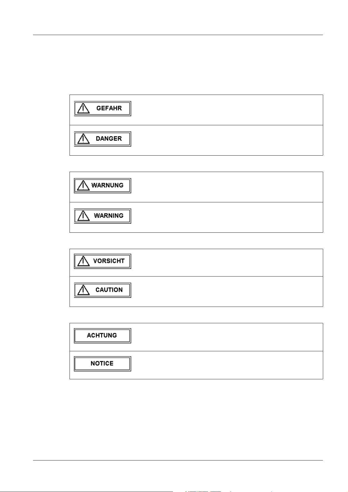
Emphasized text in this technical documentation has the following meanings:
Tab. 1 GEFAHR / DANGER
Bei einer unmittelbar drohenden Gefahr, die bei Nichtvermeidung
zum Tod oder zu einer schweren Körperverletzung führt.
Indicates when there is an immediate danger that leads to death
or serious physical injury.
Tab. 2 WARNUNG / WARNING
Bei einer Gefahr, die bei Nichtvermeidung zum Tod oder zu
einer schweren Körperverletzung führen kann.
Indicates a risk of danger that may lead to death or serious physical injury.
Tab. 3 VORSICHT / CAUTION
Tab. 4 ACHTUNG / NOTICE
Bei einer Gefahr, die bei Nichtvermeidung zu einer leichten oder
mittleren Körperverletzung und/ oder zu einer Sachbeschädigung führt oder führen kann.
Indicates a risk of danger that leads to slight or moderate physical injury and/or damage to property.
Bei einer Gefahr, die bei Nichtvermeidung zu einem unerwünschten Ergebnis oder Zustand führt oder führen kann (nicht Tod ,
Körperverletzung oder Sachbeschädigung).
Indicates a risk of danger that if disregarded leads or may lead to
a potential situation which may result in an undesirable result or
state (not death, physical injury or property damage).
Siemens AG SPR2-310.815.01.07.02 ARCADIS Varic
Medical Solutions
12.06 CS PS SP
Page 5 of 64
Page 6

6 General information
Tab. 5 HINWEIS / NOTE
Ist als Tipp zu verstehen. Der Anwender muss diese Anweisung
nicht unbedingt beachten. Er erfährt jedoch Vorteile, wenn er
dies tut.
Should be understood as a tip. The user does not absolutely
have to observe these instructions. However, there will be
advantages if he does.
ARCADIS Varic SPR2-310.815.01.07.02 Siemens AG
12.06 CS PS SP
Page 6 of 64
Medical Solutions
Page 7

General information 7
Additionally required documents 1.1
• ARCADIS Varic operating instructions
• ARCADIS Varic system wiring diagram
• IQ test (quality assurance)
• Local printer (optional) assembly and setting instructions
• Image intensifier laser light localizer (optional) assembly and setting instructions
• Single tank laser light localizer (optional) assembly and setting instructions
Siemens AG SPR2-310.815.01.07.02 ARCADIS Varic
Medical Solutions
12.06 CS PS SP
Page 7 of 64
Page 8

8 General information
Safety information 1.2
General safety information (in existing documents) 0
WARNING
Danger of injuries, death or material damage.
Non-compliance can lead to death, injury or material damage.
Please note:
¹ The product-specific safety information in these instruc-
tions,
¹ The general safety information in TD00-000.860.01... and
¹ The safety information in accordance with ARTD Part 2.
General electrical safety information 0
WARNING
Electrical safety!
Non-compliance can lead to severe injury or even death, as well
as material damage.
¹ Parts under electrical voltage are accessible when the
covers are open. To avoid danger, disconnect the system
from the power supply before opening the covers. Disconnect the power plug.
¹ If an uninterruptible power supply (UPS) is installed in
the system, the voltage output of the UPS must also be
deenergized or the voltage output plug must be disconnected.
¹ If work steps must be performed using electrical power,
the general safety information according to
TD00-000.860.01... must be observed.
Main system control board D1 and power board D2
WARNING
Danger high voltage!
When the system is switched off, there is still electrical voltage on
boards D1 and D2 of the main system.
Disregarding safety precautions can result in death or serious
bodily injury.
¹ Therefore before working on one of these boards, make
sure that the LED V400 has gone out. This is the case 3
minutes after the ARCADIS Varic system is switched off.
ARCADIS Varic SPR2-310.815.01.07.02 Siemens AG
12.06 CS PS SP
Page 8 of 64
Medical Solutions
Page 9
General information 9
Radiation safety information 0
WARNING
X-ray radiation!
Non-compliance can lead to illness, irreversible damage to body
cells and the genotype, severe injury and even death.
During work on the system in which radiation must be released,
the radiation protection directives and the rules for radiation protection according to ARTD-002.731.02.. must be complied with.
Please note:
¹ Use available radiation protection devices.
¹ Wear radiation protection clothing (lead apron).
¹ Stay as far away as possible from the radiation source.
¹ Release radiation only if necessary.
¹ Set the radiation activity as low as possible. (low kV and
mA values, short radiation time)
¹ Release radiation for as short a time as possible.
X ¹ Checks requiring the release of radiation are identified by
the radiation warning symbol shown on the left.
Systems equipped with an I.I. laser light localizer or a single tank laser light localizer
CAUTION
NOTE
Laser emissions!
This product contains class 2 lasers. (USA: Class 2 laser)
Disregarding safety precautions can lead to bodily injury, especially to the retina of the eye, resulting in irreversible damage to
vision.
¹ Observe the safety information in ARTD-002.731.03...
When working with the laser light localizer, do not look
directly into the laser beam.
Laser emissions!
There is no direct hazard to the eye (blinking reflex). Nevertheless
do not look directly into the laser beam.
0
Siemens AG SPR2-310.815.01.07.02 ARCADIS Varic
Medical Solutions
12.06 CS PS SP
Page 9 of 64
Page 10

10 General information
Systems equipped with an integrated I.I. laser light localizer 0
CAUTION
Laser emissions!
This product contains lasers of the class 1M.
Disregarding safety precautions can lead to bodily injury, especially to the retina of the eye, resulting in irreversible damage to
vision.
¹ Observe the safety information in ARTD-002.731.03...
When working with the laser light localizer, do not view
the laser beams directly with optical instruments.
ARCADIS Varic SPR2-310.815.01.07.02 Siemens AG
12.06 CS PS SP
Page 10 of 64
Medical Solutions
Page 11

General information 11
Information on the protective conductor resistance test 0
Observe the instructions in the "Safety Rules for Installation and Repair"
(ARTD-002.731.17 ...).
The protective conductor resistance of 0.2 ohms must not be exceeded.
First measured value
In the case of systems thoroughly tested at the factory prior to delivery, the protective conductor resistance test was already performed and the measured values were recorded in
the system test protocol.
The measurements were performed using the measuring procedures and measuring
equipment recorded in the system test protocol.
The test protocol is included with the accompanying documentation.
If no covers were opened while installing the system and no additional components (e.g.
options) were installed or modified, the values recorded in the test protocol including the
measuring point (e.g. cover of the basic unit or cover of the image intensifier) can be
transferred to the protective conductor resistance protocol as the first measured values.
If the power plug was changed during system installation, covers were removed, or additional components were installed or modified, the values provided in the test protocol are
invalid.
The values must be labeled invalid. Cross out the values, enter the comment "invalid
value" and confirm this with name, date and signature.
The protective conductor test must be performed again after all work has been completed.
In the case of systems with no measured values for the protective conductor test recorded
in the system test protocol, the protective conductor test must be performed after all work
has been completed.
Measurement
The measurement must be performed in accordance with DIN VDE 0751, Part 1 (refer to
ARTD Part 2). The protective conductor resistance for all touchable conductive parts must
be measured during the normal operating state of the system.
Make sure that control cables or data cables between the system components are not
mistaken for protective conductor connections.
During the measurement, the power cable and additional connection cable with the integrated protective conductor (e.g., monitor cable between the basic unit and monitor cart)
must be moved section by section to detect cable breaks.
The protective conductor resistance must not exceed 0.2 ohms.
The values, including the measuring points, must be recorded as first measured values in
the protective conductor resistance protocol.
The measuring procedure and the measuring device used (designation and serial number) must also be documented.
Siemens AG SPR2-310.815.01.07.02 ARCADIS Varic
Medical Solutions
12.06 CS PS SP
Page 11 of 64
Page 12
12 General information
Separate the page with the protocol from these instructions and file it in the "Protocols"
register in the system binder or log book.
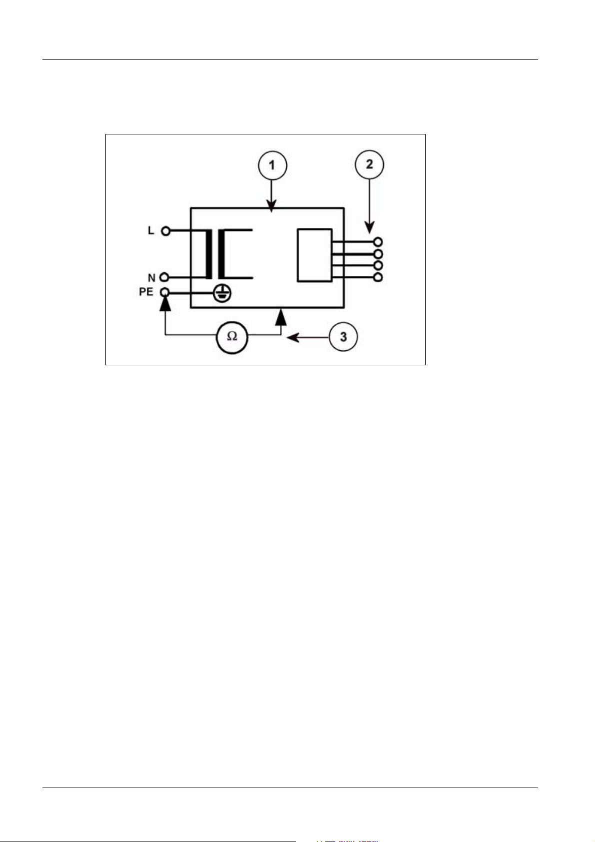
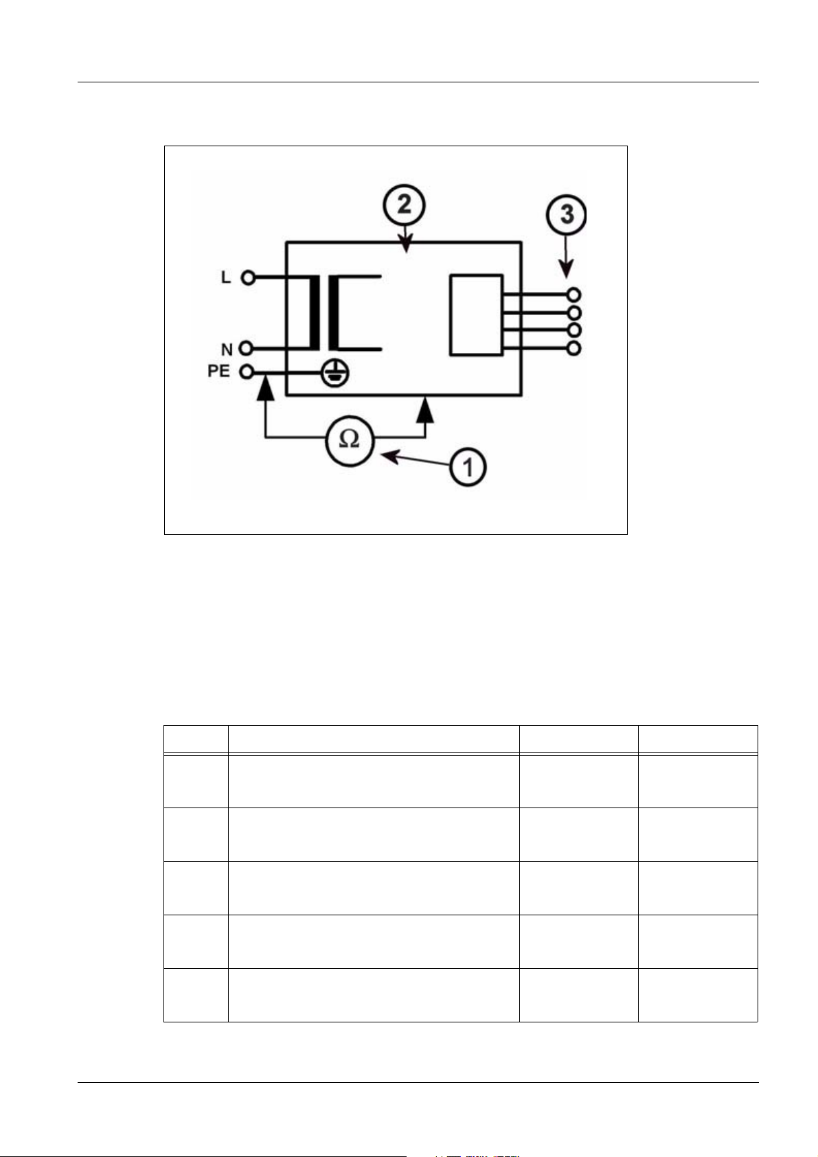
Fig. 1: Measuring circuit for measuring the protective conductor resistance for units that are
ARCADIS Varic SPR2-310.815.01.07.02 Siemens AG
12.06 CS PS SP
Page 12 of 64
Medical Solutions
Page 13

General information 13
disconnected from power, in compliance with DIN VDE 0751-1/2001-10, Fig. C2.
Pos. 1 = Syste m
Pos. 2 = Application part type B (if available)
Pos. 3 = Measurement setup (integrated into measuring device)
Repeat measurement
In the case of maintenance or repairs, perform the protective conductor resistance measurement again.
Document and evaluate the values determined in the repeat measurement.
The measurement must be performed in accordance with DIN VDE 0751, Part 1 (refer to
ARTD Part 2). The protective conductor resistance for all touchable conductive parts must
be measured during the normal operating state of the system.
Make sure that control cables or data cables between the system components are not
mistaken for protective conductor connections.
During the measurement, the power cable and additional connection cables with the integrated protective conductor (e.g. monitor cable between the basic unit and monitor cart)
must be moved section by section to detect cable breaks.
The protective conductor resistance must not exceed 0.2 ohms.
The values determined in the repeat measurement, including the measuring points, must
be recorded and evaluated in the protective conductor resistance protocol.
The measuring procedure and the measuring device used (designation and serial number) must also be documented.
NOTE
For evaluation purposes, the first measured value and the values
documented during previous maintenance or safety checks must
be compared to the measured values. A sudden or unexpected
increase in the measured values may indicate a defect in the protective conductor connections (protective conductor or contacts)
- even if the limit value of 0.2 ohms is not exceeded.
System leakage current measurement information 0
Observe the instructions in the "Safety Rules for Installation and Repair"
(ARTD-002.731.17 ...).
Siemens AG SPR2-310.815.01.07.02 ARCADIS Varic
Medical Solutions
12.06 CS PS SP
Page 13 of 64
Page 14

14 General information
WARNING
Electrical voltage!
Non-compliance can lead to severe injury and even death.
¹ The system leakage current measurement may be per-
formed on systems of protection class I only after the
protective conductor test has been passed.
First measured value
In the case of systems thoroughly tested at the factory prior to delivery, the system leakage current measurement was already performed at the factory and the measured value
was recorded in the system test protocol.
The measurement was performed using the line voltage and line frequency, the measuring procedure, and the measuring equipment recorded in the system test protocol.
The test protocol is included with the accompanying documentation.
When the line voltage and line frequency match, the value recorded in the test protocol
must be used as the first measured value in the system leakage current protocol.
If the local line voltage or line frequency differs from the delivery state of the system or if
no measurement was performed and recorded at the factory, the system leakage current
must be measured.
If the local line voltage or line frequency differs from the delivery state of the system, the
values listed in the test protocol are invalid.
The values must be labeled invalid. The reason for newly determining the first measured
value must be documented and confirmed with date, name, and signature.
Adjust/program the system to the local line voltage/line frequency before the measurement.
In the case of systems with no measured values for the system leakage current measurement recorded in the system test protocol, the system leakage current measurement must
be performed after all work has been completed.
Measurement
Perform the measurement according to DIN VDE 0751, Part 1 (see ARTD-002.731.17....),
and record the determined value as the first measured value.
Measurement of the system leakage current according to the differential current method
(measurement setup according to (Fig.2/p.15)) must be given preference, since this
method is not dangerous to the person performing the measurement and other persons.
However, please note the minimum resolution of the system leakage current measuring
device and any additional manufacturer information restricting the use of the measuring
device.
ARCADIS Varic SPR2-310.815.01.07.02 Siemens AG
12.06 CS PS SP
Page 14 of 64
Medical Solutions
Page 15
General information 15
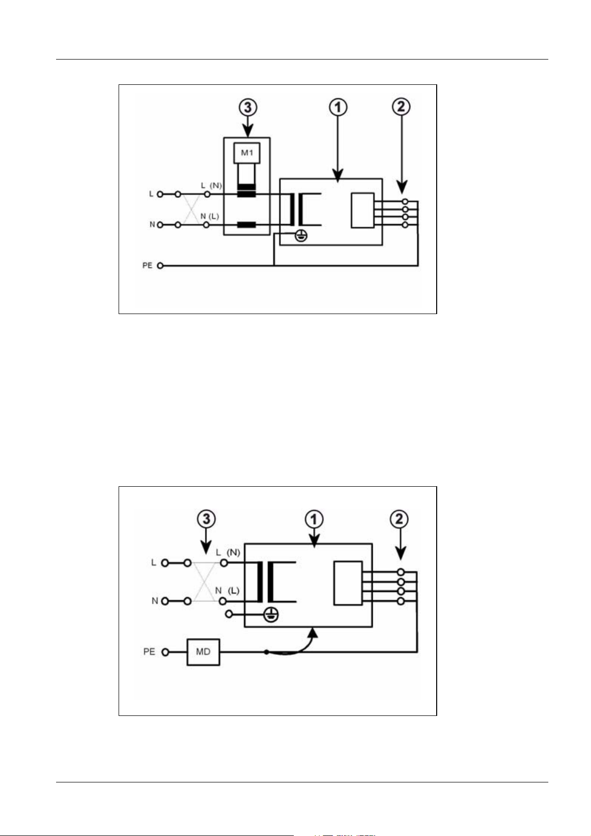
Fig. 2: Measuring circuit for measuring the system leakage current according to the differential
current method in compliance with DIN VDE 0751-1/2001-10, Fig. C6 for protection
class I.
Pos. 1 = Syste m
Pos. 2 = Application part type B (if available)
Pos. 3 = Measurement setup (integrated into measuring device)
If the direct measurement of the system leakage current is used (measurement setup
according to (Fig.3/p.15)), the system must be insulated during the measurement and
must not be touched.
Fig. 3: Measuring circuit for direct measurement of the system leakage current in compliance
Siemens AG SPR2-310.815.01.07.02 ARCADIS Varic
Medical Solutions
12.06 CS PS SP
Page 15 of 64
Page 16

16 General information
with DIN VDE 0751-1/2001-10, Fig. C5 for protection class I.
Pos. 1 = Syste m
Pos. 2 = Application part type B (if available)
Pos. 3 = Measurement setup (integrated into measuring device)
ARCADIS Varic SPR2-310.815.01.07.02 Siemens AG
12.06 CS PS SP
Page 16 of 64
Medical Solutions
Page 17

General information 17
WARNING
Electrical voltage!
Non-compliance can lead to severe injury and even death.
¹ No housing parts of the system may be touched during
direct measurement of the system leakage current (measurement setup according to (Fig.3/p.15)).
¹ Third-person access to the system must be prevented.
The system must be switched on during measurement. Measuring devices with automated measuring sequences must therefore be set to manual measurement.
Enter the highest value as the first measured value in the system leakage current protocol.
This value must not exceed the permissible leakage current values according to DIN VDE
0751-1/2001-10, Table F.1, line "system leakage current for units according to remarks 1
and 3" of
2.5 mA.
Measure and record the current line voltage. If the measured line voltage deviates from
the nominal voltage, correct the measured value to the value corresponding to a measurement at the nominal value of the line voltage. This must also be documented.
Document the measuring procedure (differential measurement or direct measurement)
and the measuring device used (designation and serial number).
Separate the protocol sheet from these instructions and attach it to the protocols already
in the system binder or log book.
Repeat measurement
When maintenance or repair work is performed on the primary power supply circuit (e.g.
repairs to the power-on circuit or replacement of the line filter), the system leakage current
measurement must be repeated.
The same measuring conditions as in the first measurement apply.
Record and evaluate the highest value determined in the repeat measurement in the
existing system leakage current protocol.
This value must not exceed the permissible leakage current values according to DIN VDE
0751-1/2001-10, Table F.1, line "system leakage current for units according to remarks 1
and 3" of
2.5 mA.
Measure and record the current line voltage. If the measured line voltage deviates from
the nominal voltage, correct the measured value to the value corresponding to a measurement at the nominal value of the line voltage. This must also be documented.
Document the measuring procedure (differential measurement or direct measurement)
Siemens AG SPR2-310.815.01.07.02 ARCADIS Varic
Medical Solutions
12.06 CS PS SP
Page 17 of 64
Page 18

18 General information
and the measuring device used (designation and serial number).
NOTE
For evaluation purposes, the first measured value and the values
documented during previous maintenance or safety checks must
be compared to the measured values. A sudden or unexpected
increase in the measured values may indicate that a fault has
occurred in the primary power supply circuit (insulation damage,
damage from moisture, defective interference suppressor, etc.) even if the limit value of 2.5 mA is not exceeded.
ARCADIS Varic SPR2-310.815.01.07.02 Siemens AG
12.06 CS PS SP
Page 18 of 64
Medical Solutions
Page 19

General information 19
Tools, aids (partially for IQ test) 1.3
• Tool case 97 02 457 Y1971
• Dynamic test case 37 90 156 X1963
• Copper filter set 44 06 120 RV090
• Densitometer 97 02 416 Y1996
• Radiation filter set (incl. 25 mm Al) 97 98 596 G5321
• Resolution test 28 71 820 RE999
• Safety tester (leakage current and ground wire testing device)
e.g. Unimed 1100
51 38 727 Y0766
Siemens AG SPR2-310.815.01.07.02 ARCADIS Varic
Medical Solutions
12.06 CS PS SP
Page 19 of 64
Page 20

20 General information
Note on the log book 1.4
The log book is located in the monitor cart behind the keyboard. It is accessible if the
cover on the back of the monitor cart is removed.
ARCADIS Varic SPR2-310.815.01.07.02 Siemens AG
12.06 CS PS SP
Page 20 of 64
Medical Solutions
Page 21

General information 21
Notes on adapting the power plug to local conditions. 1.5
The customer can have the power plug on the supplied power cable replaced with an
appropriate local plug by an electrician, provided that:
• The power plug used can conduct the power required for the operation of the ARCADIS
Varic (refer to current and voltage values stated on the line voltage label, back of monitor cart).
• The required line internal resistance is reached (refer to ARCADIS Varic Planning
Guide).
• The selectivity of the fuse protection is assured - according to the relevant national
standards.
It must also be ensured by the customer that connection to an unsuitable power supply is
prevented (e.g. by identification or design measures).
As concluding measures, perform and document protective ground wire measurements
(in Germany e.g. in the medical device book).
Siemens AG SPR2-310.815.01.07.02 ARCADIS Varic
Medical Solutions
12.06 CS PS SP
Page 21 of 64
Page 22

22 General information
Power line connection information 1.6
The delivery state of the system with respect to the power line connection values is indicated by the line voltage label or in the operating instructions.
Any necessary adjustments to local conditions must be performed in accordance with the
service instructions/the circuit diagram of the system.
The system leakage current measurement guidelines must be observed.
WARNING
Electrical voltage!
Non-compliance can lead to severe bodily injury and even death.
¹ The internal uninterruptible power supply of the system
(UPS) provides several components with line voltage even when the system is switched off or the system
power plug is disconnected.
¹ Before the system is programmed to the local line volt-
age/line frequency, it must be disconnected from the
power supply (the power plug must be disconnected)
and the voltage output plug of the UPS must be disconnected as well.
ARCADIS Varic SPR2-310.815.01.07.02 Siemens AG
12.06 CS PS SP
Page 22 of 64
Medical Solutions
Page 23

General Start-up 23
Power connection 0
2- 2General Start-up
Measuring the local line voltage 0
• Measure the voltage and frequency at the intended outlet for the ARCADIS Varic sys-
tem.
• Compare the measured line voltage with the line voltage label on the back of the moni-
tor cart.
¹ The measured voltage (+/- tolerance) must agree with the voltage read off from
the label.
Adjusting the programmed system line voltage 0
NOTE
NOTE
Only perform if the local line voltage does not match the programmed line voltage of the delivered system.
After adjustment of the line voltage, the leakage current values
logged in the system test protocol are no longer valid.
After all covers have been closed and the protective conductor
test has been successfully completed, the system leakage current
measurement must be repeated and documented.
Observe the leakage current measurement instructions in the
"General information" chapter of these instructions.
WARNING
Danger high voltage!
Disregarding safety precautions can result in death or serious
bodily injury.
¹ Before the line voltage is adapted, the power plug on the
UPS in the monitor cart must be disconnected, since the
monitor cart is not free of voltage after the power plug is
pulled out.
• Remove the back, bottom covers (Fig.4/p.24) from the monitor cart.
• Pull the power plug out of the UPS in the monitor cart.
• Adapt the voltage by changing the connections to transformers T1 and T2. Refer to the
ARCADIS Varic wiring diagram.
Siemens AG SPR2-310.815.01.07.02 ARCADIS Varic
Medical Solutions
12.06 CS PS SP
Page 23 of 64
Page 24

24 General Start-up
Fig. 4: Monitor cart line voltage
Pos. 1 Power plug
Pos. 2 T1 and T2
ARCADIS Varic SPR2-310.815.01.07.02 Siemens AG
12.06 CS PS SP
Page 24 of 64
Medical Solutions
Page 25

General Start-up 25
Function check of the emergency stop switches 2.1
• Connect the system to the voltage and boot it.
• Click "Emergency" for the patient registration.
• Operate the EMERGENCY STOP switch on the C-arm.
• The safety switch moves audibly and the following message appears on the lower left
monitor edge: "The emergency stop has been pressed"
• Disengage the EMERGENCY STOP switch.
• The safety switch moves audibly and the following message appears on the lower left
monitor edge: "The emergency stop switch has been released."
• Document the function of the EMERGENCY STOP switch in the "Test protocol, C-arm
movement and emergency stop.
Siemens AG SPR2-310.815.01.07.02 ARCADIS Varic
Medical Solutions
12.06 CS PS SP
Page 25 of 64
Page 26

26 General Start-up
Checking the temperature indicator 2.2
• Check the temperature indicator on the outside of the image intensifier housing.
¹ If the inner, square field of the indicator is white, the temperature has not been
exceeded. Remove the temperature indicator.
¹ If the indicator is discolored (inner field black), proceed according to IQ docu-
ment RXD0-000-038.01.xx.xx.
ARCADIS Varic SPR2-310.815.01.07.02 Siemens AG
12.06 CS PS SP
Page 26 of 64
Medical Solutions
Page 27

General Start-up 27
Function checks 2.3
Operation of the ARCADIS Varic, see operating instructions
• Stand and C-arm system movements
X
X
• Semi-transparent slot and iris diaphragm in fluoroscopy procedure.
• Collimation of the semi-transparent slot and iris diaphragm using fluoroscopy proce-
dure.
• Mechanical functions of the monitor cart
Siemens AG SPR2-310.815.01.07.02 ARCADIS Varic
Medical Solutions
12.06 CS PS SP
Page 27 of 64
Page 28

28 General Start-up
Functional test of C-arm lift movement and parking brakes 2.4
Fig. 5: C-arm movement functional test
• Switch on the main system (C-arm).
• To move the C-arm downward, press the downward button.
• The lifting column moves to position 1 (1/Fig.5/p.28) and remains there automati-
cally. A stop signal (3 beeps) sounds simultaneously.
• To lower the lifting column further, press the downward button once again.
• The lifting column can then be moved by a further 5 cm to the lowest point, position 2
(2/Fig.5/p.28). In this area a signal (3 beeps) sounds for safety reasons each time the
downward button is pressed.
• To move the C-arm upward, press the upward button. No signal sounds in this case.
• The lift motor remains stationary if both buttons are pressed simultaneously.
• Loosen the different parking brakes and apply them again. Secure blocking of the rele-
vant movement must be assured.
• Document the function of the C-arm movements, brakes and warning signals in the test
protocol, "C-arm movement and emergency stop" .
ARCADIS Varic SPR2-310.815.01.07.02 Siemens AG
12.06 CS PS SP
Page 28 of 64
Medical Solutions
Page 29
Specific system settings 29
System configuration 0
3- 3Specific system settings
Note regarding Hibernation Mode 0
NOTE
Customer and country-specific configurations 0
Hibernation Mode
With the introduction of the Hibernation Mode, system configuration changes are not applied if the system is switched off and
then switched on again using the power buttons on the monitor
cart.
To correctly apply the modified data, perform a system shutdown.
Open the <Options> - <End Session> menu and click the “Shutdown system” button. Immediately thereafter, press the Power off
button on the monitor cart.
The system shuts down and switches off automatically.
• Please clarify in advance with the customer whether the following system configura-
tions are required.
Service login 0
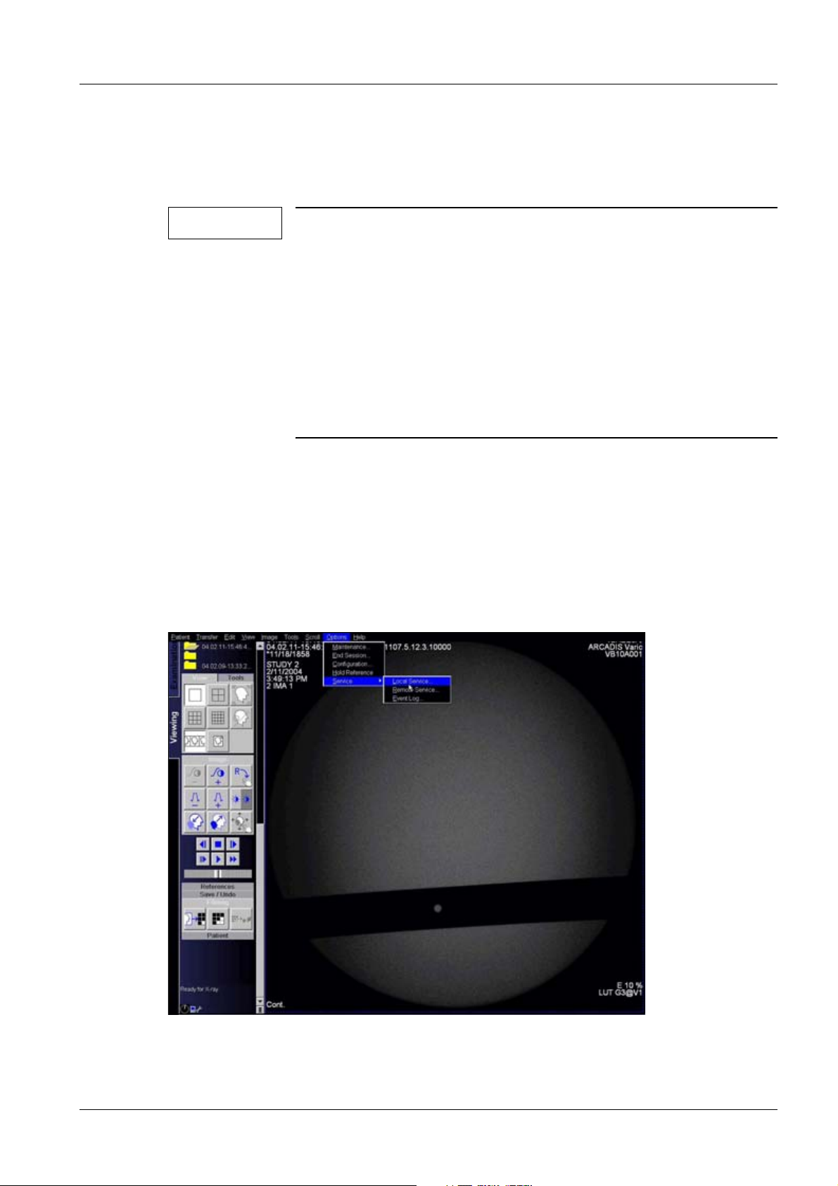
Fig. 6: Service login
• Click on <Options> <Customer service> <Local service>.
Siemens AG SPR2-310.815.01.07.02 ARCADIS Varic
Medical Solutions
12.06 CS PS SP
Page 29 of 64
Page 30

30 Specific system settings
Fig. 7: Authentication_
• Enter the 6-character password and click OK (see system folder for password).
ARCADIS Varic SPR2-310.815.01.07.02 Siemens AG
12.06 CS PS SP
Page 30 of 64
Medical Solutions
Page 31
Specific system settings 31
Customer address configuration 0
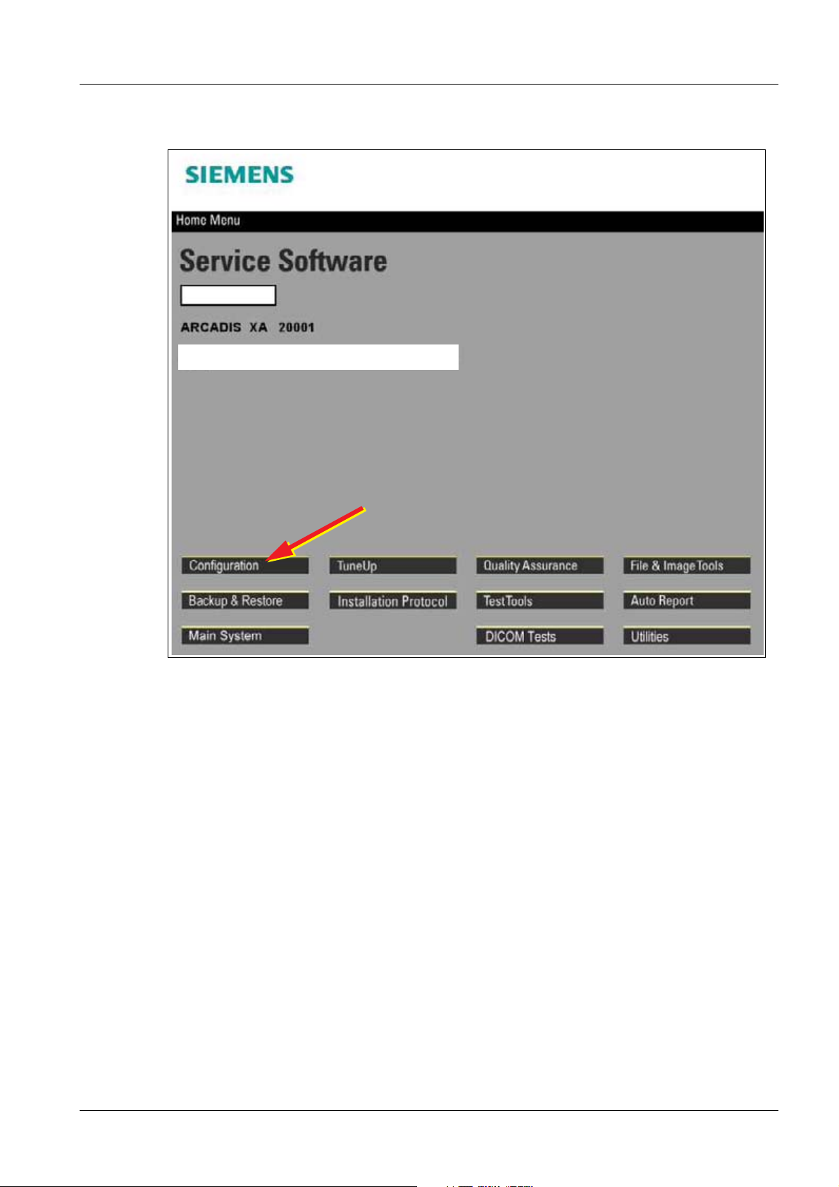
Fig. 8: Configuration_
• Click on <Configuration>.
Siemens AG SPR2-310.815.01.07.02 ARCADIS Varic
Medical Solutions
12.06 CS PS SP
Page 31 of 64
Page 32

32 Specific system settings
Fig. 9: Configuration
• Click <Next>.
Fig. 10: Configuration_Local Host
• Click <Site Info>.
ARCADIS Varic SPR2-310.815.01.07.02 Siemens AG
12.06 CS PS SP
Page 32 of 64
Medical Solutions
Page 33

Specific system settings 33
Fig. 11: Configuration_Local Host_Site Info
• The marked customer-specific data may be adapted. Under no circumstances may you
change the "serial no." or "station name".
• Click <Save>.
• Click <Home>.
Main system configuration 0
• Start the service program and log in as described under "Service Login".
Siemens AG SPR2-310.815.01.07.02 ARCADIS Varic
Medical Solutions
12.06 CS PS SP
Page 33 of 64
Page 34

34 Specific system settings
Fig. 12: Main_system
• Click <Main system>.
Fig. 13: Main system_
• Select ARCADIS Varic and click <Next>.
ARCADIS Varic SPR2-310.815.01.07.02 Siemens AG
12.06 CS PS SP
Page 34 of 64
Medical Solutions
Page 35

Specific system settings 35
Fig. 14: Main System_Configuration_Buzzer
• Under Configuration click <Buzzer>.
Make changes according to the following description:
• Block time settings
- Warning time limit: The buzzer sound starts when the entered radiation time has
elapsed.
- Block time limit: After the entered radiation time has elapsed - without reset of the
“warning time limit" - the radiation is blocked the next time it is selected. Every reset
of the “warning time limit” also resets the “block time limit” to “0”.
• Buzzer mode (direct, cassette)
- After exposure:Buzzer sound after the exposure.
- During exposure:Buzzer sound during the exposure.
• Buzzer mode (indirect, I.I.)
- Buzzer off:Buzzer sound off. Exceptions: Push mode and “warning time limit” has
ended.
- Buzzer on: Buzzer sound always during radiation.
The country-specific regulations must be observed for the max. fluoroscopy time and the
radiation blockage.
Factory setting:
Siemens AG SPR2-310.815.01.07.02 ARCADIS Varic
Medical Solutions
12.06 CS PS SP
Page 35 of 64
Page 36

36 Specific system settings
"Warning time limit" "Blocking time limit"
USA
Service mask
input in 1/10 min.
Europe
Service mask
input in 1/10 min.
5 min.
50
5 min.
50
• Make country-specific changes and click <Save>.
• Click <Home>.
• Perform a system shutdown.
• Switch on the system and wait for the system to boot.
NOTE
With the introduction of the Hibernation Mode, system configuration changes are not applied if the system is switched off and then
switched on again using the power buttons on the monitor cart.
To correctly apply the modified data, perform a system shutdown.
Open the <Options> - <End Session> menu and click the “Shutdown system” button. Immediately thereafter, press the Power off
button on the monitor cart.
0 min.
0
10 min. (5 min. + 5 min.)
50
The system shuts down and switches off automatically.
• If a change is made to "Block time settings", check this function.
Country-specific adaptation of the maximum tube current 0
NOTE
• Start service program and log in as described under "Service Login".
A maximum tube current limit is required - as far as known - only
in Denmark.
ARCADIS Varic SPR2-310.815.01.07.02 Siemens AG
12.06 CS PS SP
Page 36 of 64
Medical Solutions
Page 37

Specific system settings 37
Fig. 15: Main_system
• Click <Main system>.
Siemens AG SPR2-310.815.01.07.02 ARCADIS Varic
Medical Solutions
12.06 CS PS SP
Page 37 of 64
Page 38

38 Specific system settings
Fig. 16: Main system
• Select ARCADIS Varic and click <Next>.
Fig. 17: Main System_Configuration_Current Limitation
• Click <Current limitation>.
• Make country-specific changes (only Denmark) and click <Save>.
• Click <Home>.
• Perform a system shutdown.
ARCADIS Varic SPR2-310.815.01.07.02 Siemens AG
12.06 CS PS SP
Page 38 of 64
Medical Solutions
Page 39

Specific system settings 39
• Switch on the system and wait for the system to boot.
NOTE
With the introduction of the Hibernation Mode, system configuration changes are not applied if the system is switched off and then
switched on again using the power buttons on the monitor cart.
To correctly apply the modified data, perform a system shutdown.
Open the <Options> - <End Session> menu and click the “Shutdown system” button. Immediately thereafter, press the Power off
button on the monitor cart.
The system shuts down and switches off automatically.
Configuring the network (optional) and remote service 0
• Configure the network according to the Configuration Guide,
SPR2-310.843.01.01.xx.xx and the remote connection according to Installation, Siemens Remote Service, SP00-000.816.02.01.xx.xx.
NOTE
With the introduction of the Hibernation Mode, system configuration changes are not applied if the system is switched off and
then switched on again using the power buttons on the monitor
cart.
To correctly apply the modified data, perform a system shutdown.
Open the <Options> - <End Session> menu and click the “Shutdown system” button. Immediately thereafter, press the Power off
button on the monitor cart.
The system shuts down and switches off automatically.
Siemens AG SPR2-310.815.01.07.02 ARCADIS Varic
Medical Solutions
12.06 CS PS SP
Page 39 of 64
Page 40

40 Specific system settings
Backup 3.1
NOTE
NOTE
A backup must be created following software installation, every
software update, and every system adjustment.
After a backup group has been successfully burned to CD, the following message is displayed: "Please insert medium in CD-RW in
order to continue."
Confirm this message with "OK".
This does not require a new CD.
• Select "Backup & Restore" in the “Service Software Home Menu”
• Place the backup CD (located in the monitor cart service compartment) in the CD ROM
drive.
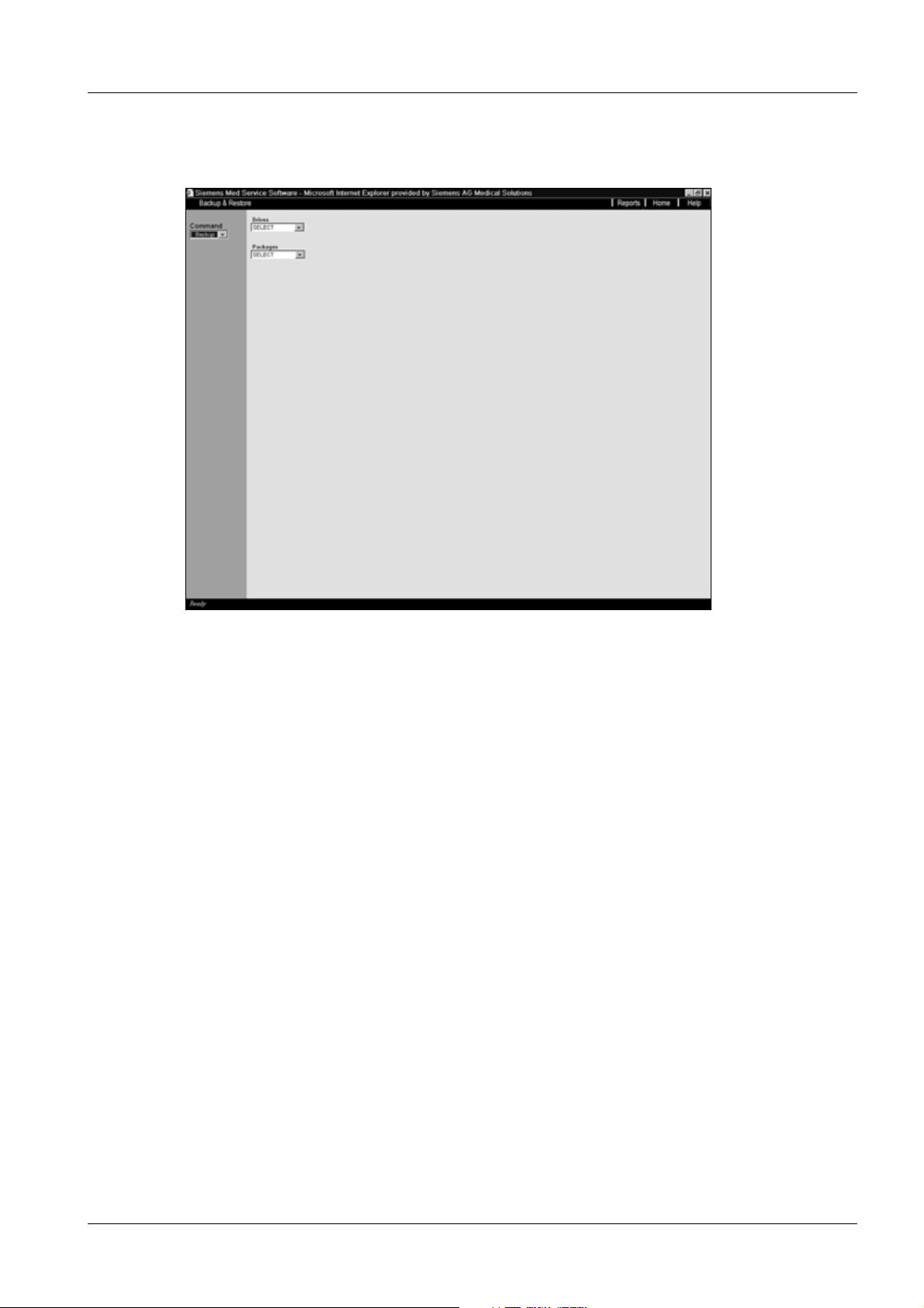
Fig. 18: Backup & Restore_Command
ARCADIS Varic SPR2-310.815.01.07.02 Siemens AG
12.06 CS PS SP
Page 40 of 64
Medical Solutions
Page 41
Specific system settings 41
• Select the <Backup> command.
Fig. 19: Backup & Restore_Command_Backup
• Select the respective drive under “Drives”.
- Save to CD ROM (standard save)
Siemens AG SPR2-310.815.01.07.02 ARCADIS Varic
Medical Solutions
12.06 CS PS SP
Page 41 of 64
Page 42

42 Specific system settings
Fig. 20: Backup & Restore_Command_Backup_Packages
SW - Settings02
• Select “SW-Settings02” under Packages
• Click <Go> and wait until the message “Ready” appears in the footer.
Fig. 21: Backup & Restore_Command_Backup_SW-Settings02
ASPIA settings
ARCADIS Varic SPR2-310.815.01.07.02 Siemens AG
12.06 CS PS SP
Page 42 of 64
Medical Solutions
Page 43

Specific system settings 43
• Select “ASPIA settings” under Packages.
• Click <Go>
- Wait until the message “Ready” is displayed in the footer
ExamSet
• Select “ExamSet” under Packages.
• Click <Go>
- Wait until the message “Ready” is displayed in the footer
Security-Settings
For systems with an HIPAA configuration
• Select “Security-Settings” under Packages.
• Click <Go>
- Wait until the message “Ready” is displayed in the footer
MainSystem
• Select “MainSystem” under Packages.
• Click <Go>
- Wait until the message “Ready” is displayed in the footer
Exiting the backup
• Close the window via <Home>.
• Remove the backup CD ROM from the CD ROM drive.
• Store the CD ROM with the other system documentation.
NOTE
It is not possible to back up the database (patient images)!
Store the patient images in an archive.
Saving to CD ROM as a long-term archive is prohibited.
Siemens AG SPR2-310.815.01.07.02 ARCADIS Varic
Medical Solutions
12.06 CS PS SP
Page 43 of 64
Page 44

44 Final Work Steps
Paper printer (optional) 0
4- 4Final Work Steps
NOTE
Codonics printer 1660L 0
Perform the following steps according to the "User Manual" of the printer:
• Transport instructions (see preface).
Please note:Unpack the printer and remove the two transport pins. Place the printer in
the cart, connect the power cable and the 25-pin plug to the printer (cables are ready for
use in the printer slot of the cart), and set the power switch to "1".
• Install the print media>(General Start-up / p. 23)
If a paper printer was ordered with the system, all mechanical
work and programming was performed at the factory.
In the case of paper printers delivered after the system, they have
to be installed and started up in accordance with the Installation
and Setting instructions SPR2-310.814.03...
NOTE
Keep the transport safety materials. They are required when
replacing or shipping the printer.
Sony printer UP-D72 X 0
Perform the following steps according to the user manual for the printer (CD-ROM):
• Unpack the printer.
• Fill the paper tray with paper (follow instructions on paper package).
• Plug in the USB cable.
• Print a test page after the automatic test.
• Follow the instructions on the CD-ROM from the manufacturer in the event of problems.
Sony Printer UP-970 and UP-990 0
Perform the following steps according to the user manual for the printer (CD-ROM):
• Unpack the printer.
• Fill the paper tray with paper (follow instructions on paper package).
• Plug in the USB cable.
• Print a test page after the automatic test.
• Follow the instructions on the CD-ROM from the manufacturer in the event of problems.
ARCADIS Varic SPR2-310.815.01.07.02 Siemens AG
12.06 CS PS SP
Page 44 of 64
Medical Solutions
Page 45

Final Work Steps 45
Final work steps 4.1
IQ test 0
• Perform IQ test according to instructions SPR2-310.820.01....
¹ Remove the supplied IQ test protocols from the monitor cart service compart-
ment.
Completing protocols 0
• After completing all adjustment work steps and check measurements, the responsible
technician must sign and date the test protocols and country-specific protocols to confirm that all values have been correctly determined and recorded.
Protective conductor resistance test 0
Transferring the values from the test protocol to the "protective conductor" protocol
NOTE
If no covers were opened while installing the system and no additional components (e.g. options) were installed or modified, the
values recorded in the test protocol 1 can be transferred as the
first measured value.
The protective conductor test need not be performed.
Perform the protective conductor resistance test if the conditions
specified above do not apply.
Refer to the section "Protective conductor resistance test during
start-up (if necessary)".
• Complete the "Protective Conductor Resistance" protocol found in the "Protocol" chap-
ter of this manual.
• If the system test protocol only contains the confirmation of the protective conductor
resistance threshold, enter this value in the "Protective conductor resistance" table, row
"Measurement point 1", column "First measured value" (< 0.18 Ohm). Enter "n.a." in
rows "measurement point 2" through "measurement point 22" of column "First measured value."
• If the system test protocol specifies the measured protective conductor resistance val-
ues and their measurement points, transfer the values to rows "Measurement point 1"
through "Measurement point 22" of column "First measured value". Mark empty fields
with "n.a." as "not applicable".
• In row "(1) Meas. circuit", column "First measured value", enter the text "VDE0751-1
Image C2".
Siemens AG SPR2-310.815.01.07.02 ARCADIS Varic
Medical Solutions
12.06 CS PS SP
Page 45 of 64
Page 46

46 Final Work Steps
• If specified in the system test protocol, read off the measuring equipment used at the
factory for the protective conductor test.
¹ Enter this measuring equipment in the "Protective conductor resistance" proto-
col, in the "Measuring device, type:" row.
• If specified in the system test protocol, read off the identification of the measuring
equipment specified in the test protocol.
¹ Enter the ID of the measuring equipment in the "Protective conductor resistance"
protocol, in the "Measuring device, Ser. No.:" row.
• Mark the following rows in the "Protective conductor resistance" protocol with "n.a." as
"not applicable":
¹ Row "Meas. inst. calibrated up to:"
¹ Row "Evaluation:"
• Complete the following rows in the "Protective conductor resistance" protocol:
¹ In the row "Date:" enter the current date.
¹ In the "Name" row, enter your name in block letters.
¹ Sign the protocol in the "Signature" row.
• If you want to complete the protocol with additional remarks, enter them in the
"Remarks" table in the protocol addendum.
Protective conductor resistance test during start-up (if necessary)
NOTE
If covers were opened while installing the system and/or additional components (e.g. options) were installed or modified, the
protective conductor resistance value recorded in system test
protocol 1 is invalid.
The protective conductor resistance test has to be performed
after closing all covers.
NOTE
Observe the instructions for the protective conductor resistance
test in the "General Information" chapter of these instructions.
• Perform the protective conductor resistance test.
¹ The protective conductor resistance must not exceed 0.2 ohms at any measuring
point.
• Complete the "First measured value" column of the "Protective conductor resistance"
protocol.
• If you want to complete the protocol with additional remarks, enter them in the
"Remarks" table in the protocol addendum.
ARCADIS Varic SPR2-310.815.01.07.02 Siemens AG
12.06 CS PS SP
Page 46 of 64
Medical Solutions
Page 47

Final Work Steps 47
Tab. 6 Measurement points for the protective conductor resistance measurement
Measuring points
Measurement from the protective conductor connection of the power plug to the:
Base unit, handle attachment screw for I.I. cover
Base unit, one attachment screw at I.I. grid
Base unit, one attachment screw at I.I.
Base unit, one attachment screw at SIREPHOS
Base unit, one screw at cover of horizontal carriage
Base unit, one screw at lifting column cover (rotational brake)
Base unit, one screw at lifting column
Base unit, a lateral screw at brake pedal
Base unit, back cover (electronics box)
Base unit, equipotential bonding connection
Base unit, base plate of electronics box (at unpainted location)
Base unit, one screw at the back of each monitor
Monitor cart, one screw at monitor support
Monitor cart, one screw at the small, top back cover
Monitor cart, one screw at the large, lower back cover
Monitor cart, one screw at back cover of switch-on assembly
Monitor cart, one screw at the front cover
Monitor cart, one screw at the right side cover
Monitor cart, one screw at the left side cover
Monitor cart, one screw at the right handle
Monitor cart, one screw at the left handle
Siemens AG SPR2-310.815.01.07.02 ARCADIS Varic
Medical Solutions
12.06 CS PS SP
Page 47 of 64
Page 48

48 Final Work Steps
Leakage current measurement 0
Transferring the values from the test protocol to the "device leakage current" protocol
NOTE
If the programmed line voltage has not been changed from its status at delivery, and there have been no changes of parts in the
system's primary circuit, the device leakage current value specified in the test protocol delivered with the system is valid.
The device leakage current test need not be performed.
The value recorded in the test protocol must be used as the "first
measured value" in the "Device Leakage Current" protocol.
Perform the device leakage current measurement if the conditions
specified above do not apply.
Refer to the section "Device leakage current measurement during
start-up (if necessary)".
• Complete the "Device leakage current" protocol found in the "Protocol" section of this
manual.
• Enter the system serial number on the "Serial Number" row of the "Device leakage cur-
rent" protocol.
• If applicable, enter the customer-specific system ID number in the "Customer-specific
ID Number" row of the "Device leakage current" protocol.
• In test protocol 1, table "Alternative leakage current measurement (DIN VDE 0751)" or
"Device leakage current measurement (DIN VDE 0751-1), read off the higher recorded
value between rows "Leakage current under normal operation and with nominal voltage" and "Leakage current with power reversion of polarity and nominal voltage."
¹ Enter the higher value from test protocol 1 in the "Device leakage current" proto-
col, row "Device leakage current (highest measured value) [mA]" and in row
"Device leakage current corrected value [mA]", column "First measured value".
• Read off the line voltage in test protocol 1 under "Revision Level".
¹ Enter the value from test protocol 1 in the "Device leakage current" protocol, row
"Line voltage during measurement [V~]", column "First measured value".
• Read off the production resources entered in test protocol 1, table "Production
resources used".
¹ Enter the production resources from test protocol 1 in the "Device leakage cur-
rent" protocol, row "Measuring device: type", column "First measured value".
• Read off the measuring device ID entered in test protocol 1, table "Production
resources used".
¹ Enter the measuring device ID from test protocol 1 in the "Device leakage cur-
rent" protocol, row "Measuring device, ser. no.", column "First measured value".
• In "Device leakage current" protocol, row "(1) Meas. circuit", column "First measured
value", enter the text "VDE0751-1 Image C5".
ARCADIS Varic SPR2-310.815.01.07.02 Siemens AG
12.06 CS PS SP
Page 48 of 64
Medical Solutions
Page 49

Final Work Steps 49
• Mark the following rows in the "Device leakage current" protocol, column "First mea-
sured value", with "n.a." as "not applicable":
¹ Row "Meas. inst. calibrated up to:"
¹ Row "Evaluation:"
• Complete the following rows in the "Device leakage current" protocol, column "First
measured value":
¹ In the row "Date:" enter the current date.
¹ In the "Name" row, enter your name in block letters.
¹ Sign the protocol in the "Signature" row.
• If you want to complete the protocol with additional remarks, enter them in the
"Remarks" table in the protocol addendum.
Device leakage current measurement during start-up (if necessary)
NOTE
If the programmed line voltage has been changed from its status
at delivery, and/or there have been changes of parts in the system's primary circuit, the device leakage current value specified
in test protocol 1 delivered with the system is no longer valid.
The device leakage current measurement has to be performed.
NOTE
WARNING
Observe the leakage current measurement instructions in the
"General Information" chapter of these instructions.
Electrical voltage!
Non-compliance can lead to severe injury and even death.
¹ The system leakage current measurement may be per-
formed on systems of protection class I only after the
protective conductor test has been passed.
• Perform the device leakage current measurement after successfully completing the
protective conductor test.
• Complete the "First measured value" column of the "Device leakage current" protocol.
• If you want to complete the protocol with additional remarks, enter them in the
"Remarks" table in the protocol addendum.
Siemens AG SPR2-310.815.01.07.02 ARCADIS Varic
Medical Solutions
12.06 CS PS SP
Page 49 of 64
Page 50

50 Final Work Steps
Completing the "ARCADIS Varic Installation" protocol 0
The manufacturer of this product requires information and the legislator demands proofs
that a product delivered free of defects from the factory continues to possess the required
and certified quality properties on installation and start-up.
It is therefore absolutely necessary that the installation report with the installation and
start-up data is sent without delay after completion of the work to the address stated on
the installation report.
You will find the report in the system folder.
ARCADIS Varic SPR2-310.815.01.07.02 Siemens AG
12.06 CS PS SP
Page 50 of 64
Medical Solutions
Page 51

Protocols 51
Protective conductor resistance 0
5- 5Protocols
System: ARCADIS Varic
Material number: 08080017
Serial number: .........................................................................
Customer-specific identification
number:
Tab. 7
First measured value Repeat measurement values
Meas. point 1:
.....................................
Meas. point 2:
.....................................
Meas. point 3:
.........................................................................
Protective conductor resistance
.....................................
Meas. point 4:
.....................................
Meas. point 5:
.....................................
Meas. point 6:
.....................................
Meas. point 7:
.....................................
Meas. point 8:
.....................................
Meas. point 9:
.....................................
Meas. point 10:
.....................................
Meas. point 11:
.....................................
Meas. point 12:
.....................................
Siemens AG SPR2-310.815.01.07.02 ARCADIS Varic
Medical Solutions
12.06 CS PS SP
Page 51 of 64
Page 52

52 Protocols
Protective conductor resistance
First measured value Repeat measurement values
Meas. point 13:
.....................................
Meas. point 14:
.....................................
Meas. point 15:
.....................................
Meas. point 16:
.....................................
Meas. point 17:
.....................................
Meas. point 18:
.....................................
Meas. point 19:
.....................................
Meas. point 20:
.....................................
Meas. point 21:
.....................................
Meas. point 22:
.....................................
(*1) Measuring circuit:
Measuring device type:
Meas. device ser. no.:
Meas. inst. calibrated up to:
Evaluation: n.a.
Date:
Name:
Signature
(*1) Measuring circuit. See (Fig. 22 / p. 53)
ARCADIS Varic SPR2-310.815.01.07.02 Siemens AG
12.06 CS PS SP
Page 52 of 64
Medical Solutions
Page 53
Protocols 53
Measuring circuit 0
Fig. 22: Measuring circuit for measuring the protective conductor resistance for units that are
Pos. 1 Measurement setup (measuring device)
Pos. 2 System
Pos. 3 Application part (if applicable)
disconnected from power, in compliance with DIN VDE 0751-1/2001-10, Fig. C2.
Comments: 0
Tab. 8
Date Comments Name Signature
Siemens AG SPR2-310.815.01.07.02 ARCADIS Varic
Medical Solutions
12.06 CS PS SP
Page 53 of 64
Page 54

54 Protocols
Date Comments Name Signature
ARCADIS Varic SPR2-310.815.01.07.02 Siemens AG
12.06 CS PS SP
Page 54 of 64
Medical Solutions
Page 55

Protocols 55
System leakage current 5.1
System: ARCADIS Varic
Material number: 08080017
Serial number: .........................................................................
Customer-specific identification
number:
Tab. 9
System leakage current
(Highest measured value)
[mA]
Line voltage during the measurement
[V~]
System leakage current
corrected value [mA]
(*1) Measuring circuit:
Measuring device type:
Meas. device ser. no.:
.........................................................................
System leakage current
First measured value Repeat measurement values
Measuring device,
calibrated to:
Evaluation:
Date:
Name:
Signature:
(*1) Measuring circuit: See (Fig. 23 / p. 56) through (Fig. 26 / p. 57)
Siemens AG SPR2-310.815.01.07.02 ARCADIS Varic
Medical Solutions
12.06 CS PS SP
Page 55 of 64
Page 56

56 Protocols
Measuring circuit 0
Direct measurement
Fig. 23: Measuring circuit for direct measurement of the system leakage current in compliance
with DIN VDE 0751-1/2001-10, Fig. C5 for protection class I.
Pos. 1 = Syste m
Pos. 2 = Application part type B (if available)
Pos. 3 = Measurement setup (integrated into measuring device)
Fig. 24: Measuring circuit for direct measurement of the system leakage current in compliance
with DIN VDE 0751-1/2001-10, Fig. C5 for protection class II.
Pos. 1 = Syste m
Pos. 2 = Application part (if applicable)
Pos. 3 = Measurement setup (integrated into measuring device)
ARCADIS Varic SPR2-310.815.01.07.02 Siemens AG
12.06 CS PS SP
Page 56 of 64
Medical Solutions
Page 57

Protocols 57
Differential measurement
Fig. 25: Measuring circuit for measuring the system leakage current according to the differential
current method in compliance with DIN VDE 0751-1/2001-10, Fig. C6 for protection
class I.
Pos. 1 = Syste m
Pos. 2 = Application part type B (if available)
Pos. 3 = Measurement setup (integrated into measuring device)
Fig. 26: Measuring circuit for measuring the system leakage current according to the differential
current method in compliance with DIN VDE 0751-1/2001-10, Fig. C6 for protection
class II.
Pos. 1 = Syste m
Pos. 2 = Application part (if applicable)
Pos. 3 = Measurement setup (integrated into measuring device)
Siemens AG SPR2-310.815.01.07.02 ARCADIS Varic
Medical Solutions
12.06 CS PS SP
Page 57 of 64
Page 58

58 Protocols
Comments: 0
Ta b . 1 0
Date Comments Name Signature
ARCADIS Varic SPR2-310.815.01.07.02 Siemens AG
12.06 CS PS SP
Page 58 of 64
Medical Solutions
Page 59

Protocols 59
C-arm movement and emergency stop 5.2
System: ARCADIS Varic
Material number: 08080017
Serial number: .........................................................................
Customer-specific identification
number:
Tab. 11 C-arm movement and emergency stop protocol
Movement OK
Releasing/locking the brakes
Downward movement, position
1
Downward movement, position
2
The warning signals sound as
described.
Function,
EMERGENCY_STOP_button
.........................................................................
Yes/No
Name Date Initials
Siemens AG SPR2-310.815.01.07.02 ARCADIS Varic
Medical Solutions
12.06 CS PS SP
Page 59 of 64
Page 60

60 Protocols
Network checklist 5.3
System: ARCADIS Varic
Material number: 08080017
Serial number: .........................................................................
Customer-specific identification
.........................................................................
number:
Network checklist (1+) For SAP order no.:_______________________
Will the system have a network connection (HIS/RIS, Camera,
Yes No
PAC S ) ?
Mandatory for image system with network connection!
To ensure that the system is preconfigured at the factory and thus optimize installation at the customer site, we
request that you complete and return this list if a network connection is available (and used).
Person responsible for network configuration at customer site
Name:
Phone / Fax:
E-mail:
System network data
Tab. 12 System network data
Identification:
Computer name *
IP address:
TCP/ IP address
Subnet mask * Configuration/ Local host/ TCP IP address
Gateways * Configuration/ Local host/ TCP IP address
General: Local AE title for:
Study transfer * Configuration/ DICOM/ General
Not networked
Configuration/ Local host/ TCP IP address
* Configuration/ Local host/ TCP IP address
HIS/RIS *
Configuration/ DICOM/ General
Print * Configuration/ DICOM/ General
ARCADIS Varic SPR2-310.815.01.07.02 Siemens AG
12.06 CS PS SP
Page 60 of 64
Medical Solutions
Page 61

Protocols 61
Remarks
Network data for HIS/RIS network partner (only with HIS/RIS option)
Tab. 13 Network data for HIS/RIS
not available
Product: Version: Manufacturer:
Host properties:
Host name
TCP/ IP address * Configuration/ DICOM/ HIS RIS nodes
General node properties
Logical name
Application entity
AE title
Port number * Configuration/ DICOM/ HIS RIS nodes
Remark:
Network checklist (2+)
Network data for reporting console / archive system (only with DICOM Basic option)
(1)
Tab. 14 Network data for reporting console/archiving system
Information on each: Reporting console/
archive system
* Configuration/ DICOM/ HIS RIS nodes
* Configuration/ DICOM/ HIS RIS nodes
* Configuration/ DICOM/ HIS RIS nodes
not available
Product: Version: Manufacturer:
Host properties:
Host name
* Configuration/ DICOM/ Network nodes
TCP/ IP address * Configuration/ DICOM/ Network nodes
General node properties:
Logical name
* Configuration/ DICOM/ Network nodes
Application entity:
AE title
* Configuration/ DICOM/ Network nodes
Por t number * Configuration/ DICOM/ Network nodes
Supported DICOM services:
Siemens AG SPR2-310.815.01.07.02 ARCADIS Varic
Medical Solutions
12.06 CS PS SP
Page 61 of 64
Page 62

62 Protocols
Storage Yes No * Configuration/ DICOM/ Network nodes
Storage commitment Yes No * Configuration/ DICOM/ Network nodes
Query Node name: * Configuration/ DICOM/ Network nodes
QueryNoYe s * Configuration/ DICOM/ Network nodes
RetrieveNoYe s * Configuration/DICOM/Network nodes
Remark:
Network data for reporting console/archive system (only with DICOM Basic option)
(2)
Tab. 15 Network data for reporting console/archiving system
Information on each: Reporting console/
not available
archive system
Product: Version: Manufacturer:
Host properties:
Host name
* Configuration/ DICOM/ Network nodes
TCP/ IP address * Configuration/ DICOM/ Network nodes
General node properties:
Logical name
* Configuration/ DICOM/ Network nodes
Application entity:
AE title
* Configuration/ DICOM/ Network nodes
Por t number * Configuration/ DICOM/ Network nodes
Supported DICOM services:
Storage Yes No
* Configuration/ DICOM/ Network nodes
Storage commitment Yes No * Configuration/ DICOM/ Network nodes
Query Node name: * Configuration/ DICOM/ Network nodes
QueryNoYe s * Configuration/ DICOM/ Network nodes
RetrieveNoYe s * Configuration/DICOM/Network nodes
Remark:
ARCADIS Varic SPR2-310.815.01.07.02 Siemens AG
12.06 CS PS SP
Page 62 of 64
Medical Solutions
Page 63

Protocols 63
Network checklist (3-)
Network data for a DICOM camera in the network (only with the DICOM Print option)
(1)
Tab. 16 Network data for DICOM camera in the network
Information for Every camera No camera available
Product: Version: Manufacturer:
Default camera Yes No
Host properties:
Host name
* Configuration/ DICOM/ Print devices
TCP/ IP address * Configuration/ DICOM/ Print devices
General node properties:
Logical name
* Configuration/ DICOM/ Print devices
Application entity:
AE title
* Configuration/ DICOM/ Print devices
Port number * Configuration/DICOM/Print devices
Remark:
Network data for a DICOM camera in the network (only with the DICOM Print option)
(2)
Tab. 17 Network data for DICOM camera in the network
Information for Every camera No camera available
Product: Version: Manufacturer:
Default camera Yes No
Host properties:
Host name
* Configuration/ DICOM/ Print devices
TCP/ IP address * Configuration/ DICOM/ Print devices
General node properties:
Logical name
* Configuration/ DICOM/ Print devices
Application entity:
AE title
* Configuration/ DICOM/ Print devices
Por t number * Configuration/DICOM/Print devices
Remark:
Siemens AG SPR2-310.815.01.07.02 ARCADIS Varic
Medical Solutions
12.06 CS PS SP
Page 63 of 64
Page 64

64 Changes to previous version
6- 6Changes to previous version
Section Changes
Specific system settings The specification for the buzzer setting for the USA was
changed as follows:
Warning time limit: changed from "45" to "50"
Blocking time limit: changed from "5" to "0"
ARCADIS Varic SPR2-310.815.01.07.02 Siemens AG
12.06 CS PS SP
Page 64 of 64
Medical Solutions
 Loading...