

Page 1

ARCADIS Varic
ARCADIS Varic
English
Operator Manual
SPR2-310.620.01.03.02
ARCADIS Varic
English
Operator Manual
SPR2-310.620.01.03.02
English
Operator Manual
SPR2-310.620.01.03.02
ARCADIS Varic
English
Operator Manual
SPR2-310.620.01.03.02
ARCADIS Varic
English
Operator Manual
SPR2-310.620.01.03.02
ARCADIS Varic
English
Operator Manual
SPR2-310.620.01.03.02
ARCADIS Varic
English
Operator Manual
SPR2-310.620.01.03.02
ARCADIS Varic
English
Operator Manual
SPR2-310.620.01.03.02
Page 2

Page 3
Operator Manual
ARCADIS Varic
VB 13 C
SP
Page 4

© Siemens AG 2006
All rights reserved
The original language of this document is German.
Contact address
Siemens AG Siemens AG, Medical Solutions
Wittelsbacherplatz 2 Special Systems
D-80333 München Henkestraße 127
Germany D-91052 Erlangen
Germany
SP
SPR2-310.620.01.03.02
Printed in Germany
AG 02/06
Page 5

ARCADIS Varic
Overall Table of Contents
Lists
Operator Manual
Overall Table of Contents
Register 1: Safety
General safety information..................................................................................................................... 3
Personal safety .................................................................................................................................... 16
Equipment safety................................................................................................................................. 24
Register 2: System Description
Description of functions......................................................................................................................... 3
Operation ............................................................................................................................................... 9
Register 3: Patient Data
Introduction to patient registration......................................................................................................... 3
Emergency registration.......................................................................................................................... 5
Registering a new patient ...................................................................................................................... 9
Registering a known patient ................................................................................................................ 13
Patient registration configuration ......................................................................................................... 19
Introduction to the Patient Browser..................................................................................................... 25
Searching for and displaying patient data ............................................................................................ 29
Updating and deleting data .................................................................................................................. 35
Patient Browser configuration ............................................................................................................. 49
Register 4: Examination
Safety information relating to the examination procedure..................................................................... 3
The Examination task card ..................................................................................................................... 5
Performing an examination .................................................................................................................... 9
References task card ........................................................................................................................... 21
Displaying reference images................................................................................................................ 25
Native task card ................................................................................................................................... 29
Displaying native images ..................................................................................................................... 30
Reports ................................................................................................................................................ 33
ARCADIS Varic
SPR2-310.620.01.03.02 1
of 2
Page 6

ARCADIS Varic
Overall Table of Contents
Register 5: Viewing
Introduction............................................................................................................................................ 3
Loading and displaying images ............................................................................................................ 13
Scrolling and selecting images............................................................................................................. 19
Editing images ..................................................................................................................................... 33
2D Evaluation (option) .......................................................................................................................... 47
DSA Evaluation .................................................................................................................................... 57
Saving, transferring, documenting, closing images ............................................................................. 61
Viewing configuration .......................................................................................................................... 69
Register 6: Filming/Printing and Archiving
Introduction to filming/printing............................................................................................................... 3
Automatic/manual filming ...................................................................................................................... 9
Viewing and processing film sheets and images................................................................................. 17
Changing film settings for a film job .................................................................................................... 33
Controlling data transfer....................................................................................................................... 43
Configuration for filming/printing ......................................................................................................... 51
Introduction to archiving ...................................................................................................................... 63
Archiving data ...................................................................................................................................... 67
Exporting data...................................................................................................................................... 71
Import/export in the file system........................................................................................................... 79
Controlling data transfer....................................................................................................................... 85
Configuration for archiving ................................................................................................................... 91
Register 7: Configuration
Examination configuration...................................................................................................................... 3
Register 8: Technical Description
Curves and diagrams ............................................................................................................................. 3
Technical data ........................................................................................................................................ 9
Labels .................................................................................................................................................. 13
Register 9: Maintenance
Functional and safety checks................................................................................................................. 3
Service support via network connection................................................................................................ 6
Cleaning and disinfection ....................................................................................................................... 9
Register 10: Accessories
Accessories............................................................................................................................................ 3
Cassette exposure ............................................................................................................................... 11
Operator Manual
2
of 2 SPR2-310.620.01.03.02
Page 7

SiemensSP04Cs2
Operator Manual
ARCADIS Varic
Safety
SP
08.03
SPR2-310.620.01.03.02EnglishEnglish
, 7777SP MSVersion 04
Cs2
Page 8

Please observe the
Safety register
This must be studied thoroughly before system startup.
The original version of this Operator Manual was written in the
German language.
© Siemens AG 2006
All rights reserved
Siemens AG, Wittelsbacherplatz 2, D-80333 München, Germany
Contact information: Siemens AG, Medical Solutions, Special Systems
Henkestraße 127, D-91052 Erlangen, Germany
Order no.: SPR2-310.620.01.03.02
SP
Printed in Germany
AG 02/06
Page 9

General safety information
Information about this Operator Manual . . . . . . . . . . . . . . . . . . . . . . 3
Warnings . . . . . . . . . . . . . . . . . . . . . . . . . . . . . . . . . . . 4
General information . . . . . . . . . . . . . . . . . . . . . . . . . . . . . 4
Information about correcting errors . . . . . . . . . . . . . . . . . . . . . 5
Names and parameters . . . . . . . . . . . . . . . . . . . . . . . . . . . 5
Laws and regulations . . . . . . . . . . . . . . . . . . . . . . . . . . . . . . . . 6
Validity . . . . . . . . . . . . . . . . . . . . . . . . . . . . . . . . . . . . . . . 6
Software . . . . . . . . . . . . . . . . . . . . . . . . . . . . . . . . . . . . . . 7
Equipotential bonding . . . . . . . . . . . . . . . . . . . . . . . . . . . . . . . . 7
Electromagnetic compatibility . . . . . . . . . . . . . . . . . . . . . . . . . . . 8
Use in connection with high frequency . . . . . . . . . . . . . . . . . . . . . . . 8
Maintenance and check . . . . . . . . . . . . . . . . . . . . . . . . . . . . . . 9
Malfunctions . . . . . . . . . . . . . . . . . . . . . . . . . . . . . . . . . . . 10
Error messages at the C-arm system . . . . . . . . . . . . . . . . . . . . 10
System messages on the monitor . . . . . . . . . . . . . . . . . . . . . . 11
Malfunction of electrics . . . . . . . . . . . . . . . . . . . . . . . . . . . . . . 12
Switching to emergency power supply . . . . . . . . . . . . . . . . . . . 12
Disconnecting the power supply plug . . . . . . . . . . . . . . . . . . . . 12
Emergency STOP . . . . . . . . . . . . . . . . . . . . . . . . . . . . . . . . . 13
Fire protection . . . . . . . . . . . . . . . . . . . . . . . . . . . . . . . . . . 14
Explosion protection . . . . . . . . . . . . . . . . . . . . . . . . . . . . . . . 14
Overload protection . . . . . . . . . . . . . . . . . . . . . . . . . . . . . . . . 15
Table of Contents
Personal safety
Open heart and skull examinations . . . . . . . . . . . . . . . . . . . . . . . . 16
Crushing hazards on the C-arm system . . . . . . . . . . . . . . . . . . . . . 16
Crushing hazards on the monitor trolley . . . . . . . . . . . . . . . . . . . . . 18
Mechanical damage . . . . . . . . . . . . . . . . . . . . . . . . . . . . . . . 18
Radiation protection . . . . . . . . . . . . . . . . . . . . . . . . . . . . . . . 19
Location and size of the relevant operating area . . . . . . . . . . . . . . 20
Maximum scatter radiation in the operating area . . . . . . . . . . . . . . 21
Radiation interruption for all operating modes . . . . . . . . . . . . . . . . 23
Equipment safety
Positioning the C-arm . . . . . . . . . . . . . . . . . . . . . . . . . . . . . . . 24
Installation, repair . . . . . . . . . . . . . . . . . . . . . . . . . . . . . . . . . 24
Original accessories . . . . . . . . . . . . . . . . . . . . . . . . . . . . . . . 25
Combination with other products/components . . . . . . . . . . . . . . . . . . 25
Attachment of dedicated options . . . . . . . . . . . . . . . . . . . . . . . . . 26
General safety requirements . . . . . . . . . . . . . . . . . . . . . . . . . 26
Tilting resistance; mechanical strength; central ray migration . . . . . . . . 26
Attachment . . . . . . . . . . . . . . . . . . . . . . . . . . . . . . . . . 26
Attenuation equivalent . . . . . . . . . . . . . . . . . . . . . . . . . . . . 27
Weight counterbalance . . . . . . . . . . . . . . . . . . . . . . . . . . . 27
Image quality . . . . . . . . . . . . . . . . . . . . . . . . . . . . . . . . . 27
Electromagnetic compatibility . . . . . . . . . . . . . . . . . . . . . . . . 27
Additional safety information . . . . . . . . . . . . . . . . . . . . . . . . 28
Disposal . . . . . . . . . . . . . . . . . . . . . . . . . . . . . . . . . . . . . . 28
ARCADIS Varic
SPR2-310.620.01.03.02 1
of 28
Page 10

Table of Contents
Operator Manual
2
of 28 SPR2-310.620.01.03.02
Page 11

Safety
General safety information
Information about this Operator Manual
Proper use of this equipment presupposes that the operating personnel are
familiar with the Operator Manual. This manual must be studied in detail prior to
starting up the system. Special attention must be given to the following sections:
❏ Safety information
❏ Functional and safety checks
❏ Personal safety
❏ Equipment safety
The operating personnel must be instructed in the proper operation of the equipment. Training must be repeated as required at appropriate intervals.
We recommend simulating emergency conditions during training so that appropriate corrective measures can be taught.
ARCADIS Varic
SPR2-310.620.01.03.02 3
of 28
Page 12

Safety
Warnings
Warning Warning is used to indicate the presence of a hazard which can cause personal
injury or death.
WARNING
At first the source of danger is stated.
Then possible consequences are pointed out.
◆ In conclusion you receive information on how to rule out any danger.
Caution Caution is used to indicate the presence of a hazard which can cause damage to
the equipment if this is used improperly.
CAUTION
At first the source of danger is stated.
Then possible consequences are pointed out.
◆ In conclusion you receive information on how to rule out any danger.
General information
Note Note is used to notify users of operator information which is important but not
hazard-related.
Notes are marked with an exclamation mark “ !” and printed in italics.
Operator Manual
4
of 28 SPR2-310.620.01.03.02
28
Page 13

Safety
Information about correcting errors
Information on how to solve problems that might occur when performing operating steps is given at the end of the relevant instructions.
In these paragraphs, the problem and the potential source of error is described.
◆ Perform these operating steps to solve the problem.
Names and parameters
All names and data of patients and institutions that are used in this Operator
Manual are entirely fictional.
Any resemblance to names of existing people or institutions past or present is
entirely coincidental.
All parameters and images shown in this manual are examples. Only the parameters displayed by your system are definite.
ARCADIS Varic
SPR2-310.620.01.03.02 5
of 28
Page 14

Safety
Laws and regulations
If legally binding regulations govern the installation and/or operation of the
system, it is the responsibility of the installer and/or the operator to observe these
regulations.
In all countries, the legally established regulations are to be observed. Deviating
from this Operator Manual, values may be set according to country-specific regulations.
This product is provided with a CE marking in accordance with the provisions of
Directive 93/42/EEC of June 14th, 1993 concerning medical devices.
Data related to individual persons are subject to data protection. Ensure compliance with all applicable laws and regulations.
Legally required tests must be performed at the specified intervals. These tests
include, for example,
❏ Constancy test according to the X-ray ordinance (§16 RöV) in the
Federal Republic of Germany.
❏ Tests based on DHHS guidelines (Department of Health and Human Services)
where applicable.
Validity
This Operator Manual applies to the following product:
❏ ARCADIS Varic
Operator Manual
6
of 28 SPR2-310.620.01.03.02
28
Page 15

Safety
Software
The system and user software used in this product is protected by copyright.
WARNING
Use of unreleased software or manipulations/modifications to released software
can lead to system malfunctions.
This can result in injury to the patient and/or damage to the equipment.
◆ Only software released by Siemens for use with this product may be used.
CAUTION
Impermissible or faulty manipulations/modifications to the software or to the
connection between the ARCADIS Varic system and the power supply can lead
to malfunctioning of the system.
Unauthorized access.
◆ Make sure all necessary precautions are taken (with the existing level of security) when changing a functionality or factory-set configuration.
CAUTION
Reduced system performance due to overload of the network environment.
Unexpected system behavior
◆ Only use the ARCADIS Varic system in a secure and load-adapted network.
Equipotential bonding
Products for which equipotential bonding is required may only be operated in
medical facilities where supplementary equipotential bonding has been installed
and tested according to DIN VDE 0107 or the relevant country-specific regulations.
Electromagnetic compatibility
This medical device complies with the requirements of the applicable standard on
electromagnetic compatibility (EMC).
ARCADIS Varic
SPR2-310.620.01.03.02 7
of 28
Page 16

Safety
(→ see Operator Manual “Information on electromagnetic compatibility”)
However, we wish to inform you that other mobile electronic devices such as
radio telephones (mobile phones) exceed the radiation limits specified in the EMC
standard and can therefore disturb functions of your medical device.
Use in connection with high frequency
The following regulations for use must be observed:
❏ IEC/TR 1289-1/07.94/
High frequency surgical equipment - Part 1: Operation
High frequency surgical equipment - Part 1: Operation
❏ IEC/TR 1289-2/08.94/
High frequency surgical equipment - Part 2: Maintenance
High frequency surgical equipment - Part 2: Maintenance
Operator Manual
8
of 28 SPR2-310.620.01.03.02
28
Page 17

Safety
Maintenance and check
Before using the equipment for examination, the user must ascertain that all
safety-relevant devices function properly and that the system is ready for operation.
Wear and tear The system is subject to mechanical and electrical wear and tear. In the interest
of the safety of patients, operating personnel and third persons, maintenance and
safety checks must be carried out every 12 months to maintain the operational
safety and reliability of the product.
Please observe the relevant information in the
(→
Register 9: Maintenance
)
CAUTION
Mechanical damage and damage to the system electrics due to improper use and
excessive load on the system.
Injury to operating personnel, patients or third persons and damage to the
product.
◆ If necessary, have the system checked more frequently.
◆ Ensure that any defects are repaired professionally.
Image quality Maintenance should include checking the image quality. Maintenance at regular
intervals is recommended to always ensure best image quality.
To ensure optimal image quality, have the following functions checked in particular as part of regular maintenance:
Pixel shift, image rotation, noise reduction, edge enhancement, subtraction,
Roadmapping.
Performing
maintenance
Maintenance work should be performed by trained technical personnel only.
If you do not have a maintenance contract, please contact Siemens Customer
Service.
If national laws or regulations specify more frequent checking and/or maintenance, this must be observed.
ARCADIS Varic
SPR2-310.620.01.03.02 9
of 28
Page 18
Safety
Malfunctions
In the event of malfunctions of the ARCADIS Varic system, call SIEMENS
Customer Service.
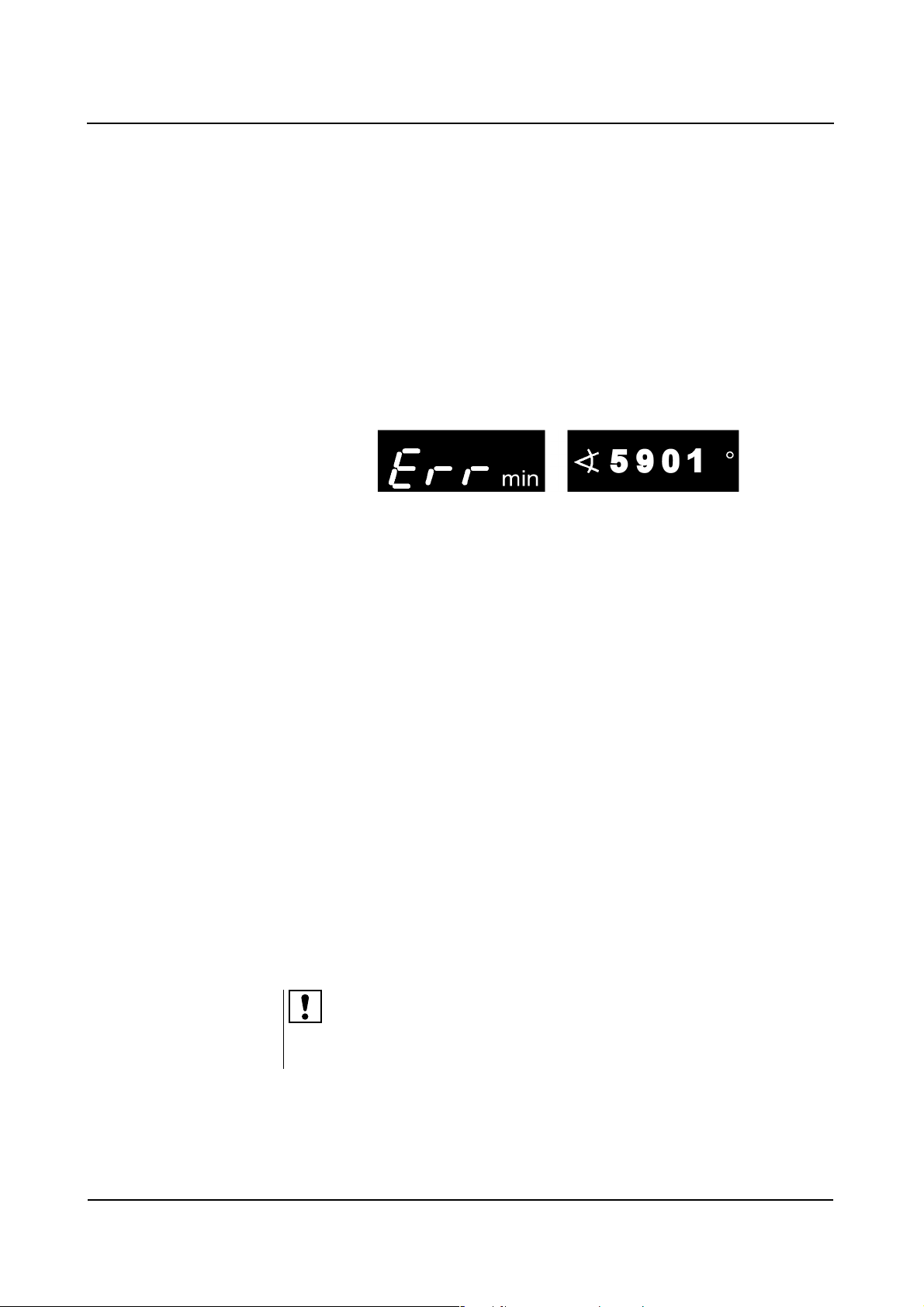
Error messages at the C-arm system
When a malfunction is detected, the ARCADIS Varic system is disabled. An error
message is displayed on the control panel of the C-arm system:
In addition, a malfunction is also displayed on the left monitor:
❏ All vital system functions are automatically checked each time the
ARCADIS Varic is switched on.
❏ During routine operation, the ARCADIS Varic is continuously monitored.
❏ Temporary error messages, such as No. 5901, can be canceled by pressing
any button on the C-arm system (except lifting column and On/Off button).
❏ Non-temporary error messages, such as No. 5015 or 5016, cannot be
canceled. If these errors occur, radiation release is no longer possible.
Please notify Customer Service immediately.
Error messages 7309 (tube unit iris collimator) and 7409 (TV camera iris) are
temporary error messages that can lead to unnecessary radiation exposure of the
user and patient if treatment is continued.
If errors occur repeatedly, switch off the ARCADIS Varic and notify Customer
Service. Have the following information ready:
❏ Error number
❏ Operating mode selected
❏ Was radiation activated when the error occurred?
❏ Is the error related to an operating process?
In case of a malfunction or failure of the radiation indicator, please notify Siemens
Customer Service.
Operator Manual
10
of 28 SPR2-310.620.01.03.02
28
Page 19
Safety
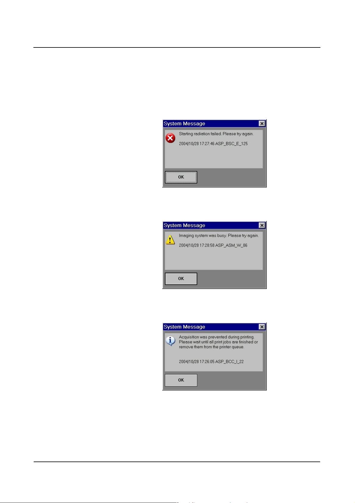
System messages on the monitor
Three different types of system messages can appear on the monitor. The type
of message is identified by a corresponding symbol (top left).
❏ Example of an error message:
❏ Example of a warning:
❏ Example of information:
You must confirm error messages with the OK button or the radiation release
button to be able to resume your work. However, warnings and information do not
disable radiation release.
ARCADIS Varic
SPR2-310.620.01.03.02 11
of 28
Page 20

Safety
Malfunction of electrics
In case of danger for patients and operating personnel (e.g. if there is no live
image on the monitor and the radiation indicator is on despite this) or danger
for the product, you must disconnect the power plug immediately. The
ARCADIS Varic will be shut down completely and disconnected from the
power supply. This will
❏ switch off radiation
❏ abort the current system program
❏ abort and cancel current operating sequences
❏ delete all image information not saved to a hard disk.
Only after the cause of the hazard has been clearly identified and remedied may
the system be reconnected to the power supply. In all other cases, e.g. system
malfunction, contact Siemens Customer Service immediately.
Switching to emergency power supply
If a power interruption lasts longer than 8 ms, the ARCADIS Varic can switch off.
In this case the ARCADIS Varic must be switched on again after switching to the
emergency power supply.
In case of a power failure, a signal sounds (up to 10 min.) when the system
switches to uninterruptible power supply (UPS).
Disconnecting the power supply plug
After disconnecting the power plug, voltage is supplied to the imaging system
and the left monitor by the uninterruptible power supply (UPS) until the
ARCADIS Varic switches off completely.
When the power plug is pulled out, switching to the uninterruptible power supply
causes an acoustic signal to be emitted. The UPS switches off after 10 min. at the
latest.
As soon as the mains supply is restored, the battery of the UPS is recharged.
Please remember that the UPS battery life is limited.
Operator Manual
12
of 28 SPR2-310.620.01.03.02
28
Page 21
Safety
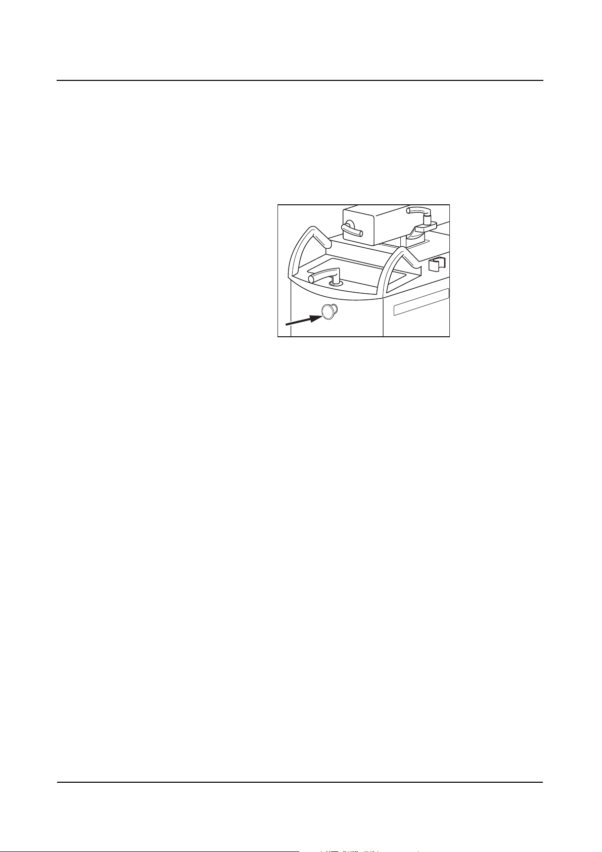
Emergency STOP
Please immediately press the red EMERGENCY STOP button (arrow) on the electronics unit of the C-arm system when a dangerous situation results from motorized movements.
STOP
❏ Motorized vertical movement is then immediately disabled.
❏ All other system functions remain unaffected by this.
Unlock the button only after the danger has clearly been eliminated.
❏ The button can be unlocked by gently turning it clockwise.
ARCADIS Varic
SPR2-310.620.01.03.02 13
of 28
Page 22

Safety
Fire protection
WARNING
In the event of fire
A fire or smoldering fire can produce toxic gases or fumes.
◆ Immediately switch off the ARCADIS Varic.
◆ Pull the power cable out of the wall outlet.
◆ Inform all personnel of the correct procedures in case of fire as part of occu-
pational safety training.
Please inform our Customer Service prior to starting up the ARCADIS Varic again
as it may require refurbishing due to damage caused by fire.
Explosion protection
WARNING
Ignitable concentration of anesthetic gases in the examination room.
Explosion hazard!
◆ The ARCADIS Varic must not be operated in such an environment.
Operator Manual
14
of 28 SPR2-310.620.01.03.02
28
Page 23

Safety
Overload protection
Prolonged continuous radiation at maximum tube load is permissible in fluoroscopy mode. However, this can cause the X-ray tube assembly to heat up. For this
reason, the X-ray tube assembly has a thermal monitor. If necessary, power is
reduced in all operating modes, in SUB/Roadmap with the next new scene/mask.
CAUTION
Heating up of the X-ray tube assembly due to continuous radiation
Burns of the skin may occur.
◆ At a temperature of ≥ 50 °C the single-tank housing must not come into
contact with the patient's skin.
The following operating states can occur:
If the temperature rises to ≥ 50 °C,
❏ the temperature indicator on the control panel of the C-arm system lights up
❏ the selected characteristic curve is switched to S1 at the end of radiation in
fluoro and pulsed fluoro.
If the temperature rises to ≥ 60 °C,
❏ the selected characteristic curve is switched to S1 during radiation in fluoro
and pulsed fluoro.
If the temperature rises to ≥ 70 °C,
❏ the temperature indicator on the control console of the C-arm system flashes
❏ radiation is aborted and cannot be released again.
If the temperature drops back below 50 °C,
❏ the previously deselected curve is automatically reselected.
ARCADIS Varic
SPR2-310.620.01.03.02 15
of 28
Page 24

Safety
Personal safety
Open heart and skull examinations
If an approved system is used alone or with other equipment for cardiac or cranial
examinations, a conductive connection must be made between the system and
a potential equalization point, e.g. the tabletop.
(→ Register 2: System Description, Page 10)
Only then may the patient be connected to the system.
Crushing hazards on the C-arm system
Correct handling of the C-arm system requires that operating personnel and
patients use only the grips provided for this purpose. Where this is not possible,
monitor the points of potential crush injury between movable system parts and
their guide openings.
WARNING
Moving and braking the C-arm (see Fig. 1 and 3).
Risk of crushing hands.
◆ Please make sure that your hands are not in the travel path of system parts.
WARNING
Maximum lowering of the C-arm (see Fig. 2)
Rish crushing feet.
◆ Please watch your feet when the C-arm is being lowered fully, since there may
not be sufficient clearance left between the I.I. and the floor.
Operator Manual
16
of 28 SPR2-310.620.01.03.02
28
Page 25

Safety
WARNING
Maximum lowering of the C-arm (see Fig. 2)
Radiation can be released inadvertently.
◆ Please make sure that the footswitch is not located underneath the C-arm.
The system areas marked in the drawings indicate points of crushing or impact
hazards for the patient or operating personnel.
(1)
(2)
(3)
(1) Potential danger points when moving and braking the C-arm
(2) Potential danger points when the C-arm is lowered fully
(3) Potential danger points when moving and braking the C-arm
ARCADIS Varic
SPR2-310.620.01.03.02 17
of 28
Page 26
Safety
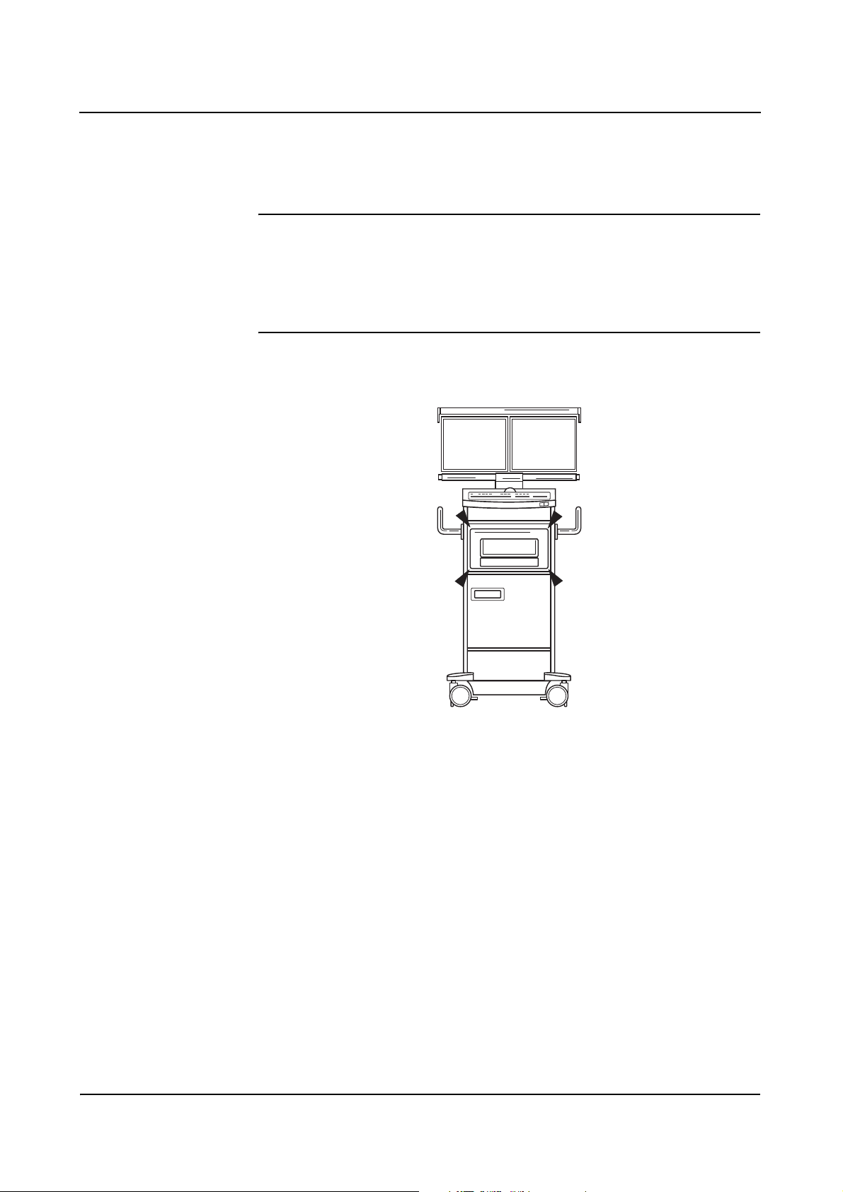
Crushing hazards on the monitor trolley
Your monitor trolley can optionally be equipped with a printer.
CAUTION
Moving the printer out or in
Risk of crushing hands.
◆ Mind your hands when moving the printer out of or into its location.
Mechanical damage
To avoid injury to the patient, operating personnel or third parties, mechanical
damage to the system must be repaired by authorized service personnel.
Operator Manual
18
of 28 SPR2-310.620.01.03.02
28
Page 27

Radiation protection
Automatic dose rate control contributes considerably to the reduction of radiation
exposure of the patient and the operator.
Nevertheless, observe the following important notes in order to keep the dose
absorbed by the patient as low as possible.
For the patient ❏ Keep the radiation field as small as possible.
❏ Provide the best possible protection for reproductive organs (gonadal shield or
lead-rubber cover) when taking exposures in the vicinity of these organs.
Safety
For the operating
personnel
For patients and
operating personnel
❏ When releasing the exposure, the operator must keep a sufficient safety
distance from the X-ray tube assembly.
❏ Wear protective clothing in the control area during an examination.
❏ Wear a radiation monitoring badge or use a pen dosimeter.
❏ Keep the fluoroscopic time as short as possible.
❏ Maintain the maximum possible source-skin distance.
Additional objects in the beam path may result in increased scattered radiation.
Please be aware that certain materials in the X-ray beam (e.g. parts of an operating table) may impair the X-ray image due to imaging of contours and inclusions
in these materials. In rare cases this can result in incorrect diagnosis. This
material may also result in a higher radiation exposure.
ARCADIS Varic
SPR2-310.620.01.03.02 19
of 28
Page 28

Safety
Location and size of the relevant operating area
Vertical beam path. Focus 170 cm (height above floor)
Relevant operating area. Dimensions in cm. (11)
(1) Tube
(2) I.I. housing
Operator Manual
20
of 28 SPR2-310.620.01.03.02
28
Page 29

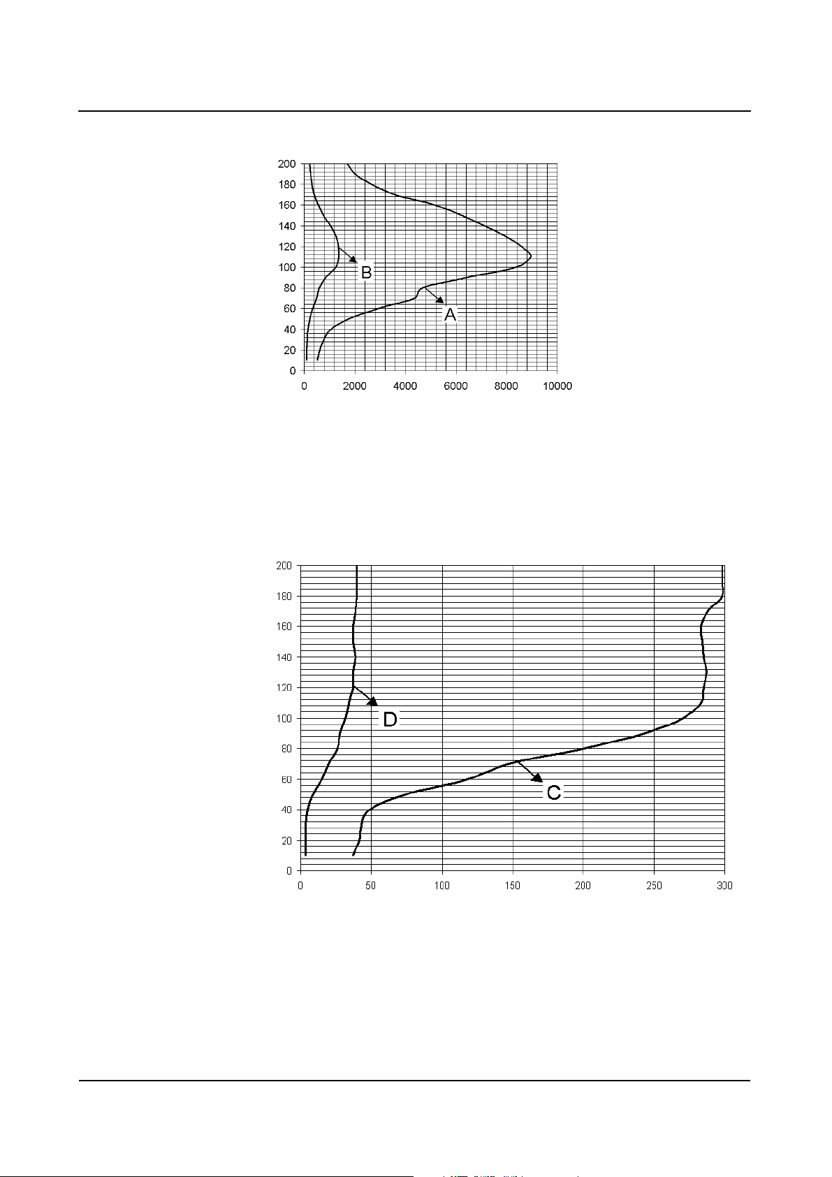
Maximum scatter radiation in the operating area
Scatter radiation in the main operating area according to EN 60601-1-3
Safety
Height above
floor [cm]
10 529 85 37 4
2061694424
30 774 129 43 4
40 1051 145 49 5
50 1760 213 75 9
60 2970 342 118 15
70 4342 491 147 20
80 4687 588 201 26
90 6394 845 244 28
100 8370 1245 270 32
110 8960 1367 283 34
120 8586 1353 285 37
130 7938 1254 287 37
140 7150 1057 285 39
Measurement A
[µGy/h]
Measurement B
[µGy/h]
Measurement C
[µGy/h]
Measurement D
[µGy/h]
150 6232 765 284 37
160 5162 555 283 37
170 3604 397 288 39
180 2657 314 298 40
190 2030 257 298 40
200 1696 220 298 40
Tolerance of air kerma measurements ± 5 %
❏ Measurement A: Operating area A
Continuous fluoroscopy 110 kV, 2.9 mA, C-arm horizontal, downward beam
direction without additional Cu filter, with scatter radiation grid
❏ Measurement B: Operating area A
Characteristic HC2 high 68 kV, 1.3 mA, C-arm horizontal, downward beam
direction without additional Cu filter, with scatter radiation grid
❏ Measurement C: Operating area B
Continuous fluoroscopy 110 kV, 2.9 mA, C-arm horizontal, downward beam
direction without additional Cu filter, with scatter radiation grid
❏ Measurement D: Operating area B
Characteristic HC2 high 68 kV, 1.3 mA, C-arm horizontal, downward beam
direction without additional Cu filter, with scatter radiation grid
ARCADIS Varic
SPR2-310.620.01.03.02 21
of 28
Page 30
Safety
cm above ground
µGy/h (power air kerma)
❏ Measurement A
Continuous fluoroscopy 110 kV, 3.0 mA
❏ Measurement B
Characteristic HC2 high, 68 kV, 1.3 mA
cm above ground
µGy/h (power air kerma)
❏ Measurement C
Continuous fluoroscopy 110 kV, 3.0 mA
❏ Measurement D
Characteristic HC2 high, 68 kV, 1.3 mA
Operator Manual
22
of 28 SPR2-310.620.01.03.02
28
Page 31

Safety
Height above floor [cm] Operating area A/
Measurement B
I.I. 23 cm/9’’ 110 < 1.4 µGy/h
Height above floor [cm] Operating area B/
Measurement D
I.I. 23 cm/9’’ 140 to 200 < 41 µGy/h
The values are valid for characteristic HC2 high, 68 kV, 1.3 mA, C-arm horizontal,
downward beam direction without additional Cu filter, with scatter radiation grid.
Height above floor [cm] Operating area A/
Measurement A
I.I. 23 cm/9’’ 110 < 9 µGy/h
Height above floor [cm] Operating area B/
Measurement C
I.I. 23 cm/9’’ 140 to 200 < 300 µGy/h
The values are valid for continuous fluoroscopy 110 kV, 2.9 mA, C-arm horizontal,
downward beam direction without additional Cu filter, with scatter radiation grid.
Radiation interruption for all operating modes
The hand switch as well as the footswitch are designed as push buttons.
By releasing the respective operating element, radiation in fluoroscopy mode is
interrupted immediately or on completion of the storage image.
ARCADIS Varic
SPR2-310.620.01.03.02 23
of 28
Page 32

Safety
Equipment safety
Positioning the C-arm
The maneuverability of the C-arm may cause the image intensifier or single tank
to collide with the patient or the patient table when the ARCADIS Varic is not
operated as specified.
With unfavorable positioning of the equipment, collisions can also take place
between the image intensifier/single tank and the unit base. This can cause
damage to the components affected.
Brakes Make sure the brakes are applied after adjusting the C-arm position.
Tr a n s p o r t When moving or transporting the C-arm system please take special care that the
system parts do not collide with an obstacle. This could also result in accidental
radiation release or an impairment of image quality under certain circumstances.
Installation, repair
Modifications or upgrades to the product must comply with legal regulations as
well as generally accepted engineering standards.
As manufacturer, SIEMENS will not be held responsible for the safety features,
reliability and performance of the product if:
❏ the product is used in a manner other than that specified in the Operator
Manual;
❏ installation, upgrades, resetting, modifications or repairs are performed by
personnel not authorized by Siemens;
❏ components affecting product safety are not replaced with original Siemens
spare parts;
❏ the electrical wiring in the rooms containing the system does not met the
specifications of DIN VDE 0107 or the corresponding local regulations.
Operator Manual
24
of 28 SPR2-310.620.01.03.02
28
Page 33

Safety
If desired, we will provide the technical documentation for the product. However,
this does not imply authorization to undertake repairs.
We cannot be held responsible for repairs made without our express written
approval.
When any work is performed on the product, we would recommend that you
obtain a certificate indicating the nature and scope of the work performed. The
certificate should include any changes in rated parameters or operating ranges as
well as the date, the name of the company and a signature.
Original accessories
For safety reasons, only approved original accessories from Siemens or accessories from other manufacturers approved by Siemens AG, Medical Solutions
Group, may be used with this product.
The operator is liable for any risks associated with the use of accessories not
approved by Siemens.
Combination with other products/
components
To ensure the required safety, only products/components expressly approved by
SIEMENS AG, Medical Solutions Group, may be used in combination with this
system.
Regarding the attachment of non-Siemens products to the image intensifier, please refer to
(→ Page 26)
Additional components that are placed into the beam path (e.g. positioning aids)
will attenuate radiation and can degrade image quality.
ARCADIS Varic
SPR2-310.620.01.03.02 25
of 28
Page 34

Safety
Attachment of dedicated options
The attachment of certain (dedicated) options is permitted only if the following
conditions are complied with:
General safety requirements
The use of accessories that do not comply with the relevant safety requirements
of this system can result in a reduced safety level of the combined system.
When choosing accessories, the following aspects must be considered in particular:
❏ Use of accessories close to the patient.
❏ Proof that the accessories have been safety tested according to the applicable
IEC 60601-1 guideline and/or the IEC 60601-1-1 harmonized national standard.
Tilting resistance; mechanical strength; central ray migration
To comply with the tilting resistance, mechanical strength and the central ray
migration standards (IEC 60601-1, IEC 60601-2-32, UL 2601, 4 times load,
IEC 60601-1-3), the additional weight attached to the image intensifier must not
exceed 4.5 kg (10 lbs).
If these conditions are not fulfilled, the function may be impaired.
Attachment
When a dedicated option is used on the image intensifier, it must be ensured that
there is no danger due to insufficient or incorrect attachment.
Operator Manual
26
of 28 SPR2-310.620.01.03.02
28
Page 35

Safety
Attenuation equivalent
According to IEC 60601-1-3, inadequate attenuation of the X-ray beam by materials between the patient and image receptor (here: I.I.) must be avoided.
Documented proof by the manufacturer is recommended.
Any auxiliary devices located in the beam path for calibration/adjustment of the
dedicated options must be removed before operating the ARCADIS Varic.
Image quality can be impaired by placing materials directly in front of the image
intensifier, or the applied dose is increased by the automatic adjustment. Additional objects in the beam path may result in increased scatter radiation.
Weight counterbalance
Attachment of additional load on the image intensifier or tube assembly side
means the loss of weight counterbalance and can lead to unwanted, unexpected
or erratic movement of the C-arm.
Users must be alerted to this by a warning label. The responsibility for affixing the
corresponding warning label lies with the company that attaches the dedicated
option to the C-arm.
Image quality
The attachment of a dedicated option, such as a navigation system, must not
affect image quality (impairment of the diagnosis).
After maintenance or service work, the correct function of the non-Siemens
system on the image intensifier (e.g. 2D navigation) must be tested.
Electromagnetic compatibility
EN 60601-1-2 must be observed in order to comply with the limit values for electromagnetic compatibility.
ARCADIS Varic
SPR2-310.620.01.03.02 27
of 28
Page 36

Safety
Additional safety information
❏ Risk of injury due to sharp edges must be avoided.
❏ To avoid thermal overloading of components and short circuits, EN 60601-1
Section 7 and, if appropriate, UL 60601-1 must be complied with.
❏ Connecting external loads to the power supply of the C-arm system is not
permitted.
❏ We recommend that users in the EU have the relevant manufacturer of the
accessory operated by you, e.g. a navigation system, confirm the CE Declaration of Conformity according to Appendix II, MDD and the Declaration of
Compatibility according to Article 12, MDD. In countries outside the EU the
relevant national regulations must be observed.
Product liability and warranty are restricted or expire if the above listed conditions
and limit values are not complied with when attaching equipment, such as navigation systems.
For non-Siemens options, such as navigation systems, we generally accept no
liability.
Disposal
There may be local regulations governing the disposal of your system:
❏ If you want to remove the product from service, take into consideration that
there may be local regulations and laws governing its disposal. To ensure that
these legal regulations are complied with and to avoid potential environmental
hazards which may be caused by the disposal of your product, we recommend
that you consult Siemens Customer Service.
❏ Batteries and packaging material must be disposed of in an environmentally
safe manner according to national regulations.
❏ For further information on the disposal of this product, please refer to the tech-
nical documentation.
Operator Manual
28
of 28 SPR2-310.620.01.03.02
28
Page 37

SiemensSP04Cs2
Operator Manual
ARCADIS Varic
System Description
SP
08.03
SPR2-310.620.01.03.02EnglishEnglish
, 7777SP MSVersion 04
Cs2
Page 38

Please observe the
Safety register
This must be studied thoroughly before system startup.
The original version of this Operator Manual was written in the
German language.
© Siemens AG 2006
All rights reserved
Siemens AG, Wittelsbacherplatz 2, D-80333 München, Germany
Contact information: Siemens AG, Medical Solutions, Special Systems
Henkestraße 127, D-91052 Erlangen, Germany
Order no.: SPR2-310.620.01.03.02
SP
Printed in Germany
AG 02/06
Page 39

Description of functions
Use . . . . . . . . . . . . . . . . . . . . . . . . . . . . . . . . . . . . . . . . . 3
System overview . . . . . . . . . . . . . . . . . . . . . . . . . . . . . . . . . . 3
Operating modes . . . . . . . . . . . . . . . . . . . . . . . . . . . . . . 4
Options . . . . . . . . . . . . . . . . . . . . . . . . . . . . . . . . . . . 4
C-arm system . . . . . . . . . . . . . . . . . . . . . . . . . . . . . . . . . . . . 5
Control and display panel on the C-arm system . . . . . . . . . . . . . . . 6
Monitor trolley . . . . . . . . . . . . . . . . . . . . . . . . . . . . . . . . . . . 7
Keyboard at the monitor trolley . . . . . . . . . . . . . . . . . . . . . . . 8
Operation
Startup . . . . . . . . . . . . . . . . . . . . . . . . . . . . . . . . . . . . . . . 9
Connecting the C-arm system with the monitor trolley . . . . . . . . . . . 9
Establishing the equipotential bonding connection . . . . . . . . . . . . . 10
Switching the ARCADIS Varic system on . . . . . . . . . . . . . . . . . . 11
C-arm movements . . . . . . . . . . . . . . . . . . . . . . . . . . . . . . . . 12
Operating the brakes . . . . . . . . . . . . . . . . . . . . . . . . . . . . . 12
Lifting and lowering the C-arm . . . . . . . . . . . . . . . . . . . . . . . . 13
Moving the C-arm horizontally . . . . . . . . . . . . . . . . . . . . . . . . 15
Swiveling the C-arm . . . . . . . . . . . . . . . . . . . . . . . . . . . . . 16
Angulating the C-arm . . . . . . . . . . . . . . . . . . . . . . . . . . . . 17
Moving the C-arm orbitally . . . . . . . . . . . . . . . . . . . . . . . . . . 18
Preparing exposure . . . . . . . . . . . . . . . . . . . . . . . . . . . . . . . . 19
Positioning the C-arm . . . . . . . . . . . . . . . . . . . . . . . . . . . . 19
Setting the collimator . . . . . . . . . . . . . . . . . . . . . . . . . . . . 19
Image quality . . . . . . . . . . . . . . . . . . . . . . . . . . . . . . . . . 20
Selecting the image intensifier format . . . . . . . . . . . . . . . . . . . . 21
Positioning an image for fluoroscopy . . . . . . . . . . . . . . . . . . . . 22
Selecting the operating mode . . . . . . . . . . . . . . . . . . . . . . . . 23
Setting the X-ray parameters manually . . . . . . . . . . . . . . . . . . . 28
Radiation release . . . . . . . . . . . . . . . . . . . . . . . . . . . . . . . . . 30
Using the hand switch . . . . . . . . . . . . . . . . . . . . . . . . . . . . 30
Using the footswitch . . . . . . . . . . . . . . . . . . . . . . . . . . . . . 32
Shutdown . . . . . . . . . . . . . . . . . . . . . . . . . . . . . . . . . . . . . 33
Switching the system off . . . . . . . . . . . . . . . . . . . . . . . . . . 34
Reactivating the system . . . . . . . . . . . . . . . . . . . . . . . . . . . 36
Transport . . . . . . . . . . . . . . . . . . . . . . . . . . . . . . . . . . . . . 37
Transport and parking position of the C-arm system . . . . . . . . . . . . 37
Monitor trolley transport position . . . . . . . . . . . . . . . . . . . . . . 40
Table of Contents
ARCADIS Varic
SPR2-310.620.01.03.02 1
of 42
Page 40

Table of Contents
Operator Manual
2
of 42 SPR2-310.620.01.03.02
Page 41

System Description
Description of functions
Use
The ARCADIS Varic is a mobile X-ray system designed for use in surgery, trauma
centers, endoscopy and ambulatory patient care. ARCADIS Varic offers the
following operating modes for its wide application spectrum: Digital Radiography,
Fluoroscopy, Pulsed Fluoroscopy, Digital Subtraction (option) and Roadmapping
(option). These are necessary for the performance of a wide variety of clinical
procedures, such as intraoperative bile duct display, nail implant, display of bones,
fluoroscopic techniques used in pain therapy, and positioning of catheters and
probes.
System overview
The ARCADIS Varic consists of a C arm system and a monitor trolley.
(1)
(1) C-arm system with a 23 cm image intensifier and single-focus tube with
generator
(2) Monitor trolley with keyboard, mouse, two TFT displays, CD R/W drive and
memory for 40,000 images
(2)
ARCADIS Varic
SPR2-310.620.01.03.02 3
of 42
Page 42

System Description
Operating modes
The ARCADIS Varic has the following operating modes:
❏ Continuous Fluoroscopy (CFC)
❏ Pulsed Fluoroscopy (PFC) with 8 f/s
❏ Digital Radiography (DR)
Options
The following options are available for the ARCADIS Varic:
❏ Additional operating modes Subtraction and Roadmap
❏ Pulsed Fluoroscopy (PFC) 15 f/s
❏ Fluoro Loop
❏ 2 TFT High-contrast black/white displays (alternative to TFT color displays)
❏ Monitor Out Live
❏ Monitor Out Live & Reference
❏ DICOM Standard (Send/Receive, Storage Commitment, Print)
❏ DICOM Query/Retrieve (Enhancement of DICOM Standard)
❏ DICOM Worklist (Enhancement of DICOM Standard)
❏ DICOM MPPS (Enhancement of DICOM Standard)
❏ DICOM Advanced (Send/Receive, Storage Commitment, Print,
Query/Retrieve, Worklist, MPPS)
❏ DSA/Roadmap
❏ NaviLink 2D
Integrated digital navigation interface for lossless transfer of 2D image data to
a navigation system
❏ 2D measuring function (For measuring angles and distances)
❏ HIPAA (Health Insurance Portability and Accountability Act)
❏ Local paper printer
❏ Local film printer
❏ Dose measuring chamber for dose area product/air kerma
❏ Integrated I.I. laser aimer
❏ Single-tank laser targeting device
❏ DHHS spacer
❏ Grounding cable
Operator Manual
4
of 42 SPR2-310.620.01.03.02
Page 43

System Description
❏ Sterile covers for the image intensifier, X-ray tube assembly and C-arm
❏ Set of clamps
❏ Cassette exposure
C-arm system
The C-arm system comprises the following components:
(6)
(7)
(5)
(4)
(3)
(2)
(1)
(1) Electronics unit
(2) Control and display panel
(3) Lifting column
(4) Horizontal support arm
(5) C-arm
(6) Handle
(8)
(7) Image intensifier with integrated TV camera
(8) Single tank with X-ray tube unit and integrated collimator
ARCADIS Varic
SPR2-310.620.01.03.02 5
of 42
Page 44

System Description
Control and display panel on the C-arm system
On the C-arm system you can find the control and display panel with membrane
keys and digital displays for performing your examinations.
The individual keys and displays are grouped by their functions in different areas.
(7)
SUB
DR
(1)
ROAD
MAP
mA
(9)(10)
kV
R
(2)
mAs
mA min
R
(3)
(4)
BA
(5)
A
(8)
B
B B
(6)
(1) Selection of operating modes
(2) Selection of Power Mode, parameter setting and image reversal keys
(3) Collimator setting
(4) Radiation indicator, power switch and X-ray tube assembly temperature
(5) Image postprocessing
(7)
(6) Image selection and storage
(7) C-arm vertical movement
(8) Image rotation
(9) Radiation time
(10) Fluoro parameters and selection of single-tank laser targeting device
(optional)
Operator Manual
6
of 42 SPR2-310.620.01.03.02
Page 45

Monitor trolley
(1)
System Description
(2)
(3)
(4)
(5)
(6)
(1) Monitor A (left); Monitor B (right)
(2) Radiation indicator
(3) Keyboard and mouse
(4) Compartment or space for options
(2)
(7)
(8)
(9)
(5) Compartment or space for options (e.g. printer)
(6) CD R/W drive
(7) On/Off button of the ARCADIS Varic
(8) Grab handles or push handles
(9) Front wheels with brakes
Back wheels with direction locks
ARCADIS Varic
SPR2-310.620.01.03.02 7
of 42
Page 46

System Description
Keyboard at the monitor trolley
The application software for preparing (e.g. entering patient data) and evaluating
examinations is operated via the keyboard at the monitor trolley.
(1) Alphanumeric keypad
(2) Cursor keys
(3) Symbol keypad
(4) Function keys
Operator Manual
8
of 42 SPR2-310.620.01.03.02
Page 47

System Description
Operation
Startup
Connecting the C-arm system with the monitor trolley
The C-arm system is connected to the monitor trolley with a cable.
The monitor trolley may only be connected to the corresponding C-arm system.
If the monitor trolley is connected to the wrong C-arm system, an error message
is displayed during system startup.
Before starting the ARCADIS Varic, please make sure that the cables are straight
(without loops).
Do not lay connection cables parallel to other cables.
1
(1) Lever
◆ Turn the lever of the central plug all the way counterclockwise.
◆ Plug the central plug into the socket on the front face of the C-arm system.
◆ Turn the lever approx. ¾ turns clockwise until it audibly locks into place and
cannot be turned any further.
– The monitor trolley is connected to the C-arm system.
ARCADIS Varic
SPR2-310.620.01.03.02 9
of 42
Page 48

System Description
Establishing the equipotential bonding connection
The ARCADIS Varic can be connected to a protective earth terminal via the equal
potential connector on the C-arm system. This will ensure that the ARCADIS Varic
has the same electrical potential as other units connected to the same protective
earth terminal.
When performing cardiac examinations or examinations of the open skull, an
additional grounding cable according to DIN 57107/VDE107 must be routed in
rooms of Application Group 2.
◆ Clamp the grounding cable to the front face of the C-arm system (arrow) and
to an equipotential bonding point in the patient vicinity.
– Equipotential bonding is established.
Operator Manual
10
of 42 SPR2-310.620.01.03.02
42
Page 49

System Description
Switching the ARCADIS Varic system on
The ARCADIS Varic is operated via a grounded wall outlet.
◆ Plug the power plug into the appropriate socket.
– The mains connection is established.
The mains cable is on the monitor trolley.
◆ Press the ON button at the monitor trolley.
– The ARCADIS Varic is switched on.
– The system automatically runs a self-test.
After approximately 3 minutes, the ARCADIS Varic is ready for operation and the
following functions are set:
Fluoroscopy mode (CFC)
Iris diaphragm in full format (edges visible)
Semi-transparent slot diaphragm in full format
Before beginning the examination, perform the daily function and safety checks.
ARCADIS Varic
SPR2-310.620.01.03.02 11
of 42
Page 50

System Description
C-arm movements
The brakes for different directions of movement are color coded. A graduation in
the same colors for the corresponding directions of movement is located on the
housing.
Operating the brakes
Before moving the C-arm, the brake for the relevant direction of movement must
be released. After that, you can move the C-arm into the desired position using
the C-arm handle or the I.I. handle.
WARNING
As long as the brakes are not locked after movement, the C-arm system moves
freely.
Risk of injury to the patient and personnel
◆ Lock the brake once the C-arm is in the required position.
◆ Release the brake.
– You can move the C-arm.
or
◆ Lock the brake.
– You can no longer move the C-arm.
Operator Manual
12
of 42 SPR2-310.620.01.03.02
42
Page 51

System Description
Lifting and lowering the C-arm
You can lift and lower the C-arm by motor control using the arrow keys on the
control panel of the C-arm system. The lifting column can be lowered to position 1
and further down to position 2.
(2)
45cm
(1) C-arm in position 1
(2) C-arm in position 2
(1)
WARNING
Hazard caused by motorized movements.
Movement of the lifting column may cause a crushing hazard.
◆ Immediately press the red EMERGENCY STOP button on the electronics unit
of the C-arm system.
ARCADIS Varic
SPR2-310.620.01.03.02 13
of 42
Page 52

System Description
Lowering the C-arm
◆ Press the Down key on the control panel of the C-arm system.
– The lifting column then moves to position 1 and automatically stops there.
A signal sounds.
◆ Press the Down key on the control panel of the C-arm system once more.
– The lifting column is lowered by another 5 cm.
The lifting column cannot be moved.
The EMERGENCY STOP button is pressed and must be unlocked.
STOP
◆ Turn the rotary knob clockwise.
The lifting column can be lowered to position 2. For safety reasons a signal
sounds each time the Down key is pressed.
Lifting the C-arm
◆ Press the Up key on the control panel of the C-arm system.
– The lifting column moves upwards. There is no acoustic signal during this
movement.
Operator Manual
14
of 42 SPR2-310.620.01.03.02
42
Page 53

System Description
Moving the C-arm horizontally
You can move the support arm horizontally by up to 20 cm.
cm
20
S
T
O
P
◆ Release the brake marked in green (arrow).
◆ Move the support arm.
– The support arm is set to the required position.
◆ Lock the brake again.
ARCADIS Varic
SPR2-310.620.01.03.02 15
of 42
Page 54

System Description
Swiveling the C-arm
You can swivel the C-arm horizontally about the system column by ± 12.5°.
12,5°
S
T
O
P
12,5°
◆ Release the brake marked in orange (arrow).
◆ Swivel the C-arm.
– The C-arm is set to the required position.
◆ Lock the brake again.
Operator Manual
16
of 42 SPR2-310.620.01.03.02
42
Page 55

System Description
Angulating the C-arm
You can rotate the C-arm vertically about the horizontal support arm by ± 190°.
190° 190°
S
T
O
P
◆ Release the brake marked in yellow (arrow).
◆ Rotate the C-arm while observing the scale on the support arm joint.
– The C-arm is set to the required position.
◆ Lock the brake again.
ARCADIS Varic
SPR2-310.620.01.03.02 17
of 42
Page 56

System Description
S
T
OP
Moving the C-arm orbitally
Starting from the a.p. position, you can swivel the C-arm from +90° horizontal to
-40° vertical (total range: 130°).
130°
130°
◆ Release the brake marked in blue (arrow).
◆ Swivel the C-arm up to the mark on the outside of the C-arm.
– The C-arm is set to the required position.
◆ Lock the brake again.
Operator Manual
18
of 42 SPR2-310.620.01.03.02
42
Page 57

System Description
Preparing exposure
Positioning the C-arm
◆ Align the ARCADIS Varic.
◆ Release the brakes and set the C-arm to the required position.
(→ Page 12)
Setting the collimator
Setting the semi-transparent slot diaphragm
The semi-transparent slot diaphragm is used primarily for collimation when
imaging the extremities.
Collimation enhances image contrast and reduces scatter radiation. Direct radiation that passes the soft tissue laterally is reduced to such an extent that the
image can be viewed on the monitor without any disturbing differences in brightness.
By rotating the slot diaphragm, the collimated field can be quickly oriented to the
direction of the anatomy under examination (e.g. the extremities).
◆ Press one of these keys.
– The semi-transparent slot diaphragms are rotated to the left/right.
◆ Press this key.
– The semi-transparent slot diaphragm is closed.
◆ Press this key.
– The semi-transparent slot diaphragm is opened.
ARCADIS Varic
SPR2-310.620.01.03.02 19
of 42
Page 58

System Description
Setting the iris diaphragm
The iris diaphragm is a collimator which serves to reduce radiation exposure to
the patient and third parties. Smaller collimation produces less scatter radiation
and therefore better image contrast. When the iris diaphragm is fully opened, it
must be visible in at least 2 places in the fluoro image.
The X iris leaves are set such that at least two leaves are visible.
When the ARCADIS Varic is switched on, the iris diaphragm automatically opens
to full format.
◆ Press this key.
– The iris diaphragm is closed.
◆ Press this key.
– The iris diaphragm is opened.
– The LED lights up.
When you open/close the iris diaphragm or move the semi-transparent slot
diaphragm without radiation, you can see the position of the collimator on the
LIH image displayed with a line/circle superimposed.
When you release radiation, the diaphragms are in the position shown in the
image.
Image quality
Selecting the noise reduction factor
◆ Press this key.
– A low integration factor is selected (for recording fast-moving objects).
When a low integration factor is selected, the LED lights up.
– If the key is pressed again, the LED goes out. A higher integration factor is
selected (for very slow movements).
Operator Manual
20
of 42 SPR2-310.620.01.03.02
42
Page 59

System Description
Selecting the image intensifier format
You can select a zoom format.
When this function is activated, the zoom format symbol is displayed in the
Examination task card and the currently set zoom format is indicated (ZOOM).
◆ Press this key.
– The LED lights up when this function is selected.
Setting image reversal
◆ Press this key.
R
– The image is flipped vertically.
– The LED lights up when this function is selected.
R
◆ Press this key.
– The image is flipped horizontally.
– The LED lights up when this function is selected.
The image reversal is effective only on the left (live) monitor.
ARCADIS Varic
SPR2-310.620.01.03.02 21
of 42
Page 60

System Description
Positioning an image for fluoroscopy
To have the image appear on the monitor in the desired orientation during fluoroscopy, you must rotate it.
Object display on the monitor depends upon the C-arm system position relative
to the patient.
(2)(1)
(1) right side of patient
(2) left side of patient
The rotation angle is displayed on the C-arm system (± 360°). The rotation angle
is displayed absolute (proportional to the original position) as well as relative
(proportional to the previous image).
◆ Press one of these keys.
– The image is rotated in the respective direction.
Operator Manual
22
of 42 SPR2-310.620.01.03.02
42
Page 61

System Description
Selecting the operating mode
You can select between up to five operating modes for the ARCADIS Varic.
Fluoroscopy For fluoroscopy (CFC) you can choose between several exam sets with different
characteristic curves to determine exposure parameters for fluoroscopy. Every
application allows to choose between different optimized programs. Continuous
Fluoroscopy is the default setting after switching on the ARCADIS Varic.
Exposure factors and system control units including the way in which the automatic setting is controlled:
2
❏ 1 K
Typical clinical procedure:
❏ Fracture reposition of the distal upper extremity (e.g. distal forearm fracture)
matrix; 30 f/s frame rate; image integration (as a function of the K factor
set), i.e. a number of K exposures are integrated into one image by sliding
averaging; the K factor can be selected between K = 1 and K = 32 and can be
assigned to an exam set and stored.
in the plaster room of an emergency outpatient clinic where, under continuous
fluoroscopy, the fracture elements are reduced by extension, fixed temporarily
in the best possible position and then fixed permanently by applying a plaster
cast.
Pulsed Fluoroscopy This operating mode (frame rates up to 15 f/s) allows a reduction in the radiation
dose of up to 70 % for the patient and operator. The pulse duration is generally
7 milliseconds. According to the level of noise reduction, many different fluoroscopic images can be integrated. For frame rates less than or equalling 2 frames
per second, a type of intermittent continuous fluoroscopy is used where the
pulse duration varies depending on the noise reduction set.
Exposure factors and system control units including the way in which the automatic setting is controlled:
2
❏ 1 K
Typical clinical procedure:
❏ Fracture reposition of the distal upper extremity (e.g. distal forearm fracture)
matrix; frame rate usually 4 to 15 f/s; image integration (as a function of
the K factor set), i.e. a number of K exposures are integrated into one image
by sliding averaging; the K factor can be selected between K = 1 and K = 8 and
can be assigned to an exam set and stored.
in the plaster room of an emergency outpatient clinic where, under continuous
fluoroscopy, the fracture elements are reduced by extension, fixed temporarily
in the best possible position and then fixed permanently by applying a plaster
cast, with the additional advantage of dose savings for the patient and medical
staff.
ARCADIS Varic
SPR2-310.620.01.03.02 23
of 42
Page 62

System Description
Digital Radiography Digital radiography (DR) provides an electronic instant image of the patient on the
monitor. DR is recommended for final exposures. The exposure time depends on
the noise reduction set.
Exposure factors and system control units including the way in which the automatic setting is controlled:
2
❏ 1 K
Typical clinical procedure:
❏ Final follow-up exposure of a fracture reposition of the distal upper extremity
matrix; 1 f/s frame rate, with image integration, depending on the setting;
X-ray pulse with 7 ms up to approx. 1400 ms width, depending on the noise
reduction set.
(see above).
Subtraction/
Roadmap (option)
The subtraction memory option allows you to perform a digital subtraction
angiography and simultaneously display the unsubtracted angiogram on the
second monitor. Subtraction technique allows hemodynamic display as well as
display of the maximum vascular filling and Roadmap. The Roadmapping features
can also be used for other interventional procedures.
Exposure factors and system control units including the way in which the automatic setting is controlled:
2
❏ 1 K
matrix; continuous fluoroscopy; storage rate usually 3 to 8 f/s; image integration (as a function of the K factor set), i.e. number of K exposures are integrated into one image; the k factor can be set between K = 1 and K = 32 by
an authorized technician.
Typical clinical procedure:
❏ Display of an arterial vessel for localizing vascular stenoses with injection of a
contrast medium to enable the contrast-enhanced display of the vascular
filling (subtraction of the native image (mask) from the contrast-enhanced
image).
❏ Alternative to native image display, subsequent inversion of the displayed
image allows you to display a catheter introduced into the vessel path using
the Roadmap function.
For information on performing an examination with Subtraction or Roadmap refer
to
(→
Register 4: Examination,
Page 17
)
Operator Manual
24
of 42 SPR2-310.620.01.03.02
42
Page 63

System Description
When an operating mode is selected, the LED of the corresponding key lights
up. On the imaging system the operating mode is indicated by a symbol or text
display. The current operating mode is deselected when you switch to another
mode.
By repeatedly pressing an operating mode key that is already activated, you can
scroll through the exam sets assigned to the corresponding operating mode.
This is possible only if a patient has been registered.
Continuous Fluoroscopy (CFC)
◆ Press this key.
– Fluoroscopy mode is selected.
– The LED lights up.
DR
When the ARCADIS Varic is switched on, it automatically defaults to
Fluoroscopy mode.
Pulsed Fluoroscopy (PFC)
◆ Press this key.
– Pulsed Fluoroscopy mode is selected.
– The LED lights up.
Digital Radiography (DR)
Digital radiography (DR) provides an electronic instant image with best image
quality. DR is recommended for final exposures.
On activation of digital radiography a short radiation pulse is released.
◆ Press this key.
– Digital Radiography mode is selected.
– The LED lights up.
Depending on the K factor selected and the build of the patient, the radiation
pulse can be > 0.5 s (EN 60601-2-7/29.1.103).
ARCADIS Varic
SPR2-310.620.01.03.02 25
of 42
Page 64

System Description
mA
High-contrast fluoroscopy (Power Mode)
For high-contrast fluoroscopy you can switch from the normal characteristic to the
“ high contrast” characteristic. This characteristic temporarily enables maximum
output in continuous fluoroscopy (CFC).
At the end of the exposure (max. 15 s) the “ high-contrast” Power Mode switches
off automatically. During the exposure an acoustic warning signal is emitted. If the
ARCADIS Varic is connected to an insufficient mains supply (e.g. high internal
resistance), the maximum time of 15 s is automatically reduced in the CFC mode.
In the DR mode, “ high contrast” is selected by default (LED lights up) and
cannot be deselected.
“ High contrast” is not possible in the PFC, SUB and Roadmap modes.
◆ Press this key.
– High contrast is selected.
– The LED lights up.
◆ Press this key again to switch "high contrast" off.
– High contrast is deselected.
If the X-ray tube overheats, high-contrast fluoroscopy cannot be selected; the
overload protection will change the characteristic curve.
(→
Register 1: Safety, Page 15
If you select another operating mode or change the exam set, the selection of
SIREMATIC curves will change. This depends on the corresponding setting of
exam sets.
)
Operator Manual
26
of 42 SPR2-310.620.01.03.02
42
Page 65

SUB
System Description
Subtraction (SUB)
The subtraction technique enables the isolated display of the vascular system
after contrast injection by means of background subtraction.
(→ Register 4: Examination, Page 17)
◆ Press this key.
– Subtraction mode is selected.
– The LED lights up.
Roadmap
The Roadmap technique allows the user to accurately place a catheter into a
blood vessel under fluoroscopy.
(→ Register 4: Examination, Page 17)
ROAD
MAP
◆ Press this key.
– Roadmap mode is selected.
– The LED lights up.
ARCADIS Varic
SPR2-310.620.01.03.02 27
of 42
Page 66

System Description
Setting the X-ray parameters manually
The default X-ray parameters can be changed manually with the +/- keys for kV/mA.
Automatic dose rate
control
Using automatic dose rate control (ADR), the mean value of the image gray values
is held constant within the dominant largely independently of the object transparency. This ensures optimal image quality for on-screen evaluation. The position of
the dominant is centered to the image intensifier input.
(→ Register 8: Technical Description, Page 4)
There are three factory default settings for the dose rate: reduced dose, standard
dose, increased dose (for 23 cm/9” image intensifier 0.11/0.185/0.37 µGy/s).
Activating ADR stop
When metallic objects (e.g. intermedullary nails) are introduced into the beam
path or when examining objects of varying density (e.g. hip prosthesis) under
fluoroscopy, it is recommended that you set the adjusted kV value with the
Dose rate control Stop key at the start of fluoroscopy.
◆ Press this key.
– The stop function is switched on, the LED lights up.
– Automatic dose control is disabled.
– The +/- keys for kV/mA are enabled.
Operator Manual
28
of 42 SPR2-310.620.01.03.02
42
Page 67

System Description
Setting the X-ray parameters manually
You can set the kV/mA values manually by activating the Dose rate control Stop
key.
◆ Press the +/- keys briefly.
– The kV/mA values are increased/reduced.
– The set values are displayed.
or
◆ Keep the +/- keys pressed for a period of time.
– This results in a continuous increase/decrease of the particular X-ray param-
eters.
– Once the upper or lower limit of the setting range is reached, an acoustic
signal is emitted every time you press the key again.
The mA values assigned to the kV values result from the SIREMATIC curves.
(→
Register 8: Technical Description, Page 3
)
On reaching the end of the curve, the iris diaphragm is opened. The LED flashes.
If the iris diaphragm is opened to maximum, an acoustic signal sounds.
ARCADIS Varic
SPR2-310.620.01.03.02 29
of 42
Page 68

System Description
Radiation release
Using the hand switch
The hand switch is used to remote control radiation release and image storage.
The hand switch can be connected on either side of the C-arm system.
(2)
(1)
(1) Button for saving images
(2) Release button
Releasing radiation
◆ Use the button to release the exposure.
– Radiation is released in the selected operating mode.
– The current radiation parameters are displayed on the control panel of the C-arm
system.
During the exposure or after ending the exposure, an acoustic warning signal
sounds (can be configured).
Operator Manual
30
of 42 SPR2-310.620.01.03.02
42
Page 69

System Description
Confirming a warning signal
When the fluoroscopic time exceeds 5 minutes, an audible alarm sounds.
◆ Press the reset key on the control panel of the C-arm system.
– The acoustic warning signal is deactivated. The fluoroscopic timer continues
to display the amount of fluoro time used.
5 Minutes after reset, the alarm signal sounds again.
10 Minutes after the last reset, radiation is automatically disabled.
Storing images (during radiation)
◆ Press this button on the hand switch during radiation.
– The image currently generated and displayed is saved in the local database.
(→ Register 4: Examination, Page 14)
Storing images (after radiation)
◆ Press this button on the hand switch.
– The last acquired image is stored.
The ARCADIS Varic transfers images from monitor A to monitor B and then
stores them in the local database.
ARCADIS Varic
SPR2-310.620.01.03.02 31
of 42
Page 70

System Description
Using the footswitch
The footswitch is used if both hands need to be free during the exposure.
DR
SUB
ROAD
(1)
(1) left footswitch
(2) right footswitch
(2)
WARNING
When the C-arm is rotated by 180° and lowered to maximum, the image intensifier could touch the footswitch.
Unintentional release of radiation
◆ Please make sure that the footswitch is not located underneath the I.I.
Releasing radiation
The right pedal is always used to activate fluoroscopy (CFC).
The left pedal is used to activate the currently selected operating mode.
Exception: If fluoroscopy (CFC) is selected, the left pedal is assigned the digital
radiography (DR) mode.
◆ Keep the foot pedal pressed during radiation release.
Operator Manual
32
of 42 SPR2-310.620.01.03.02
42
Page 71

System Description
Shutdown
Before disconnecting the ARCADIS Varic from the mains, you must shut it down.
During the shutdown procedure the imaging system is powered down. There are
two different shutdown procedures, each having a different reset time.
❏ Simple shutdown
The imaging system goes into “ Hibernate” mode before it switches off.
When the ARCADIS Varic is switched on again, it will be ready for operation
after only approx. 45 s.
Simple shutdown can be performed up to 12 times in a row. After that, a
complete shutdown is performed automatically. After you have performed the
simple shutdown procedure 10 times in a row, a message is displayed before
the system is shut down completely.
❏ Complete shutdown
The imaging system is shut down completely before it switches off. When the
ARCADIS Varic is switched on again, it will be ready for operation after approx.
3min.
For technical reasons a complete shutdown must be performed on a regular
basis. Unless initiated by you, a complete shutdown is performed automatically when the system is shut down for the 13th time.
The shutdown procedure used depends on how you switch off the ARCADIS Varic.
If you want to ensure a very short power-up time of your ARCADIS Varic system,
we recommend that you initiate a (complete) shutdown yourself before the
maximum number of 12 (simple) shutdown procedures is reached. You can do
this during a break between examinations, for example, and then switch the
ARCADIS Varic on again in time before the next examination.
ARCADIS Varic
SPR2-310.620.01.03.02 33
of 42
Page 72

System Description
Switching the system off
◆ Close the current examination by selecting Patient > End examination in the
main menu of the Examination task card.
◆ Make sure there is no CD in the drive.
If there is a CD in the drive when you restart the ARCADIS Varic, the system will
not recognize the CD drive. In this case you would have to remove the CD, switch
the system off and then restart it.
Simple shutdown
◆ Press the OFF button at the monitor trolley.
—or—
◆ Press the OFF key on the control panel of the C-arm system.
– The C-arm system is immediately switched off.
– The imaging system and monitor A switch off after the computer has been
shut down.
The system can be restarted as early as 5 seconds after pressing the OFF button
(even during shutdown).
Operator Manual
34
of 42 SPR2-310.620.01.03.02
42
Page 73

System Description
Complete shutdown
◆ Select Options > End Session in the main menu at the monitor trolley.
–The End Session dialog box opens.
◆ Click Shut down system.
– The imaging system is completely shut down.
◆ Press the OFF button at the monitor trolley.
—or—
◆ Press the OFF key on the control panel of the C-arm system.
– The C-arm system, the imaging system and the monitors are switched off.
ARCADIS Varic
SPR2-310.620.01.03.02 35
of 42
Page 74

System Description
Reactivating the system
If the imaging system cannot be shut down properly after pressing the OFF
button and does not react any more, you must deactivate the ARCADIS Varic
system as follows:
◆ Press the Reset button at the bottom of the key panel at the monitor trolley.
– All running processes are aborted and the ARCADIS Varic is shut down.
◆ Switch the ARCADIS Varic on again and let it boot up completely.
– Now you can either continue using the ARCADIS Varic or shut it down.
If the ARCADIS Varic is not fully operational in spite of resetting it, please notify
Customer Service.
Operator Manual
36
of 42 SPR2-310.620.01.03.02
42
Page 75

System Description
Transport
The C-arm system is equipped with 4 wheels for easy steering in any direction.
The C-arm system can be locked in place with the foot brake.
CAUTION
When transporting the C-arm system as well as the monitor trolley, the incline of
the ramp or floor must not exceed ± 10°.
The C-arm system can tip over.
◆ Avoid an inclination of more than ± 10°.
Transport and parking position of the C-arm system
Prior to transport, the C-arm system must be set to the transport position.
Prior to transport
◆ Release all brakes on the C-arm.
◆ Set the C-arm to the transport position shown in the drawing.
◆ Lower the lifting column down to position 2.
(→ Page 13)
◆ Move the horizontal carriage all the way back, if possible.
◆ Lock all brakes on the C-arm again.
ARCADIS Varic
SPR2-310.620.01.03.02 37
of 42
Page 76

System Description
Disconnect the power plug
◆ Switch off the ARCADIS Varic and wait for it to shut down.
◆ Pull the power plug out of the wall outlet.
Pull on the plug, not on the cable!
The ARCADIS Varic can be switched on again after approx. 5 s.
Please note that after finishing an examination, the ARCADIS Varic must be shut
down properly before it is disconnected from the power supply.
Disconnecting the central plug
◆ Turn the lever ¾ counterclockwise and remove the plug.
– The central plug is disconnected from the monitor trolley.
◆ If attached, disconnect the grounding cable from the C-arm system.
Rolling up the footswitch cable
◆ Roll up the footswitch cable at the front of the unit and attach the footswitch.
When attaching the footswitch, please be careful not to kink the cable.
Operator Manual
38
of 42 SPR2-310.620.01.03.02
42
Page 77

Driving the unit
System Description
(1)
(2)
(1) Foot brake locked
(2) Foot brake released
◆ Release the foot brake.
(1)
(2)
STOP
STOP
(1) Steering lever shown in the position for forward travel
(2) The steering lever can be locked into position for transverse travel to the right
or left
◆ Lift the steering lever and turn it in the desired direction.
The steering lever can be locked into three different positions. One is for
movement straight ahead, the others for transverse travel to the right or left.
◆ Move the C-arm system by hand.
ARCADIS Varic
SPR2-310.620.01.03.02 39
of 42
Page 78

System Description
– If the steering lever is in a transverse position, the C-arm system moves
parallel to the lever position.
When transporting the C-arm system make sure there are no obstructions on the
floor.
Monitor trolley transport position
During transport, the rolled-up power cable and the connection cable for the C-arm
system should be placed on the cable holders on the back of the monitor trolley.
Do not place the rolled-up cables on the handles.
Depositing the connection cable
◆ Place the rolled-up cable on the transport holders.
Operator Manual
40
of 42 SPR2-310.620.01.03.02
42
Page 79

System Description
Driving the unit
(1)
(2)
◆ Release the brakes (blue footswitches) on the front wheels
(see arrow (1)).
◆ Use the directional locks on the back wheels for long straight distances
(see arrow (2)).
ARCADIS Varic
SPR2-310.620.01.03.02 41
of 42
Page 80

System Description
Operator Manual
42
of 42 SPR2-310.620.01.03.02
42
Page 81

SiemensSP04Cs2
Operator Manual
ARCADIS Varic
Patient Data
SP
08.03
SPR2-310.620.01.03.02EnglishEnglish
, 7777SP MSVersion 04
Cs2
Page 82

Please observe the
Safety register
This must be studied thoroughly before system startup.
The original version of this Operator Manual was written in the
German language.
© Siemens AG 2006
All rights reserved
Siemens AG, Wittelsbacherplatz 2, D-80333 München, Germany
Contact information: Siemens AG, Medical Solutions, Special Systems
Henkestraße 127, D-91052 Erlangen, Germany
Order no.: SPR2-310.620.01.03.02
SP
Printed in Germany
AG 02/06
Page 83

Introduction to patient registration
The Patient Registration window . . . . . . . . . . . . . . . . . . . . . . . . . . 4
Emergency registration
Emergency Registration window . . . . . . . . . . . . . . . . . . . . . . . . . . 6
Emergency registration in the Patient Registration window . . . . . . . . . . . . 8
Registering a new patient
Calling up the Patient Registration window . . . . . . . . . . . . . . . . . . . . . 9
Entering data . . . . . . . . . . . . . . . . . . . . . . . . . . . . . . . . . . . 10
Personal data . . . . . . . . . . . . . . . . . . . . . . . . . . . . . . . . . 10
Hospital-specific data . . . . . . . . . . . . . . . . . . . . . . . . . . . . 11
Examination data . . . . . . . . . . . . . . . . . . . . . . . . . . . . . . . 11
Institution data . . . . . . . . . . . . . . . . . . . . . . . . . . . . . . . . 11
Completing data entry . . . . . . . . . . . . . . . . . . . . . . . . . . . . . . 12
Registering a patient for examination . . . . . . . . . . . . . . . . . . . . 12
Preregistering a patient . . . . . . . . . . . . . . . . . . . . . . . . . . . 12
Registering a known patient
Searching in the Patient Registration window . . . . . . . . . . . . . . . . . . 14
Starting a search . . . . . . . . . . . . . . . . . . . . . . . . . . . . . . . 14
Accepting patient data . . . . . . . . . . . . . . . . . . . . . . . . . . . . 15
Searching in the Patient Browser . . . . . . . . . . . . . . . . . . . . . . . . . 16
Completing your entries . . . . . . . . . . . . . . . . . . . . . . . . . . . . . 17
Resuming a commenced study . . . . . . . . . . . . . . . . . . . . . . . . . . 18
Table of Contents
Patient registration configuration
Calling up the configuration window . . . . . . . . . . . . . . . . . . . . . . . 19
Configuring selection lists . . . . . . . . . . . . . . . . . . . . . . . . . . . . 20
Configuring patient search . . . . . . . . . . . . . . . . . . . . . . . . . . . . 22
Introduction to the Patient Browser
The Patient Browser window . . . . . . . . . . . . . . . . . . . . . . . . . . . 26
Databases and drives . . . . . . . . . . . . . . . . . . . . . . . . . . . . . . . 27
Data levels . . . . . . . . . . . . . . . . . . . . . . . . . . . . . . . . . . . . 28
Searching for and displaying patient data
Data at the workstation . . . . . . . . . . . . . . . . . . . . . . . . . . . . . . 29
Opening a data level . . . . . . . . . . . . . . . . . . . . . . . . . . . . . 29
Filtering data . . . . . . . . . . . . . . . . . . . . . . . . . . . . . . . . . 30
Sorting data . . . . . . . . . . . . . . . . . . . . . . . . . . . . . . . . . 31
Data on external exchange media . . . . . . . . . . . . . . . . . . . . . . . . 31
Data in the network . . . . . . . . . . . . . . . . . . . . . . . . . . . . . . . . 32
Printing a data list . . . . . . . . . . . . . . . . . . . . . . . . . . . . . . . . . 34
ARCADIS Varic
SPR2-310.620.01.03.02 1
of 60
Page 84

Table of Contents
Updating and deleting data
Changing patient or examination data . . . . . . . . . . . . . . . . . . . . . . 35
Safety notes for changing data . . . . . . . . . . . . . . . . . . . . . . . 36
Correcting data . . . . . . . . . . . . . . . . . . . . . . . . . . . . . . . . 37
Rearranging data . . . . . . . . . . . . . . . . . . . . . . . . . . . . . . . 40
History of changes . . . . . . . . . . . . . . . . . . . . . . . . . . . . . . . . 41
Changing the work status . . . . . . . . . . . . . . . . . . . . . . . . . . . . 42
Performance Documentation (MPPS) . . . . . . . . . . . . . . . . . . . . . . 43
Adding data . . . . . . . . . . . . . . . . . . . . . . . . . . . . . . . . . 44
Sending and concluding a report . . . . . . . . . . . . . . . . . . . . . . . 44
Deleting data . . . . . . . . . . . . . . . . . . . . . . . . . . . . . . . . . . . 46
Deleting patient data . . . . . . . . . . . . . . . . . . . . . . . . . . . . . 46
Protecting data from deletion . . . . . . . . . . . . . . . . . . . . . . . . 47
Removing delete protection . . . . . . . . . . . . . . . . . . . . . . . . . 47
Deleting data in the scheduler . . . . . . . . . . . . . . . . . . . . . . . . 48
Patient Browser configuration
Calling up the configuration window . . . . . . . . . . . . . . . . . . . . . . . 49
General settings . . . . . . . . . . . . . . . . . . . . . . . . . . . . . . . . . 50
Configuring the tool bar . . . . . . . . . . . . . . . . . . . . . . . . . . . 51
Work status . . . . . . . . . . . . . . . . . . . . . . . . . . . . . . . . . 52
Delete confirmation . . . . . . . . . . . . . . . . . . . . . . . . . . . . . 53
Tree view . . . . . . . . . . . . . . . . . . . . . . . . . . . . . . . . . . . . . 54
Selecting a database and a data level . . . . . . . . . . . . . . . . . . . . 55
List entries . . . . . . . . . . . . . . . . . . . . . . . . . . . . . . . . . . 56
Hiding data levels . . . . . . . . . . . . . . . . . . . . . . . . . . . . . . 56
Single view . . . . . . . . . . . . . . . . . . . . . . . . . . . . . . . . . . . . 57
Selecting a database and a data level . . . . . . . . . . . . . . . . . . . . 58
List entries . . . . . . . . . . . . . . . . . . . . . . . . . . . . . . . . . . 59
Configuring patient search . . . . . . . . . . . . . . . . . . . . . . . . . . . . 60
Operator Manual
2
of 60 SPR2-310.620.01.03.02
Page 85

Patient Data
Introduction to patient registration
Before you can examine a patient with your system, you must register the patient.
Registration means that you give your system all the information about a patient
that it requires for an examination.
Depending on how registrations are organized in your hospital and how much
time you have for registration, you can choose between different patient registration procedures.
Emergency
registration
Registration for the
examination
Preregistration If you want to prepare the system to examine a patient at a later time, then you
HIS/RIS query If your system is connected to a HIS/RIS system (hospital and radiology informa-
If a patient is admitted who is in an extremely critical condition and must therefore
be examined and treated immediately, call up emergency registration. This
reduces the time before you can begin the examination to a minimum.
However, if you want to register a patient for an examination, you first enter the
patient's data or call it up from the database and then examine the patient.
can preregister the patient.
For example, in the morning you can enter the data of all the patients to be
examined during the day. When you want to begin an examination, simply call up
the relevant data and edit them, if necessary. This saves time during the examination.
tion system), you can query and retrieve data for the patient to be examined for
preregistration or registration.
ARCADIS Varic
SPR2-310.620.01.03.02 3
of 60
Page 86

Patient Data
The Patient Registration window
The Patient Registration window is subdivided into four areas into which you
can enter topically coherent data.
(1) Personal data of the patient (PATIENT)
(2) Hospital-specific data (HOSPITAL)
(3) Study-specific data (PROCEDURE)
(4) Institution data (INSTITUTION)
The input fields can be adapted by Siemens Service.
Operator Manual
4
of 60 SPR2-310.620.01.03.02
Page 87

Patient Data
Emergency registration
An emergency registration is performed if a patient must be examined and
treated immediately, without wasting time entering the patient’s data.
You can register an emergency patient either in the Emergency Registration
window or in the Patient Registration window.
If you release radiation without having registered a patient for the examination,
a corresponding dialog box is displayed. After radiation has been released
again, an emergency patient is automatically registered. You can register an
emergency patient by releasing radiation twice with the hand switch or footswitch. Thus entries at the monitor trolley are unnecessary.
Provisional patient
data
The patient is registered with provisional data as an emergency patient. As soon
as you have more time after the examination, you must complete the patient and
examination data of your emergency patient using the Patient Browser.
ARCADIS Varic
SPR2-310.620.01.03.02 5
of 60
Page 88

Patient Data
Emergency Registration window
◆ First finish off or interrupt the current examination.
◆ Press the button in the tool bar of the Patient Browser.
—or—
◆ Call up Patient > Emergency in the main menu.
–The Emergency Registration window opens.
Operator Manual
6
of 60 SPR2-310.620.01.03.02
Page 89

Patient Data
◆ Click on the Exam button in the Emergency Registration window.
–The Emergency Registration window is closed.
–The Examination task card is opened.
By clicking Cancel you can stop emergency registration at any time, e.g. if you
have accidentally called up the Emergency Registration window instead of the
Patient Registration window.
ARCADIS Varic
SPR2-310.620.01.03.02 7
of 60
Page 90

Patient Data
Emergency registration in the Patient
Registration window
◆ First finish off or interrupt the current examination.
◆ Press the key on the symbol keypad.
–The Patient Registration window is displayed.
◆ Click the Emergency button in the Patient Registration window.
–The Patient Registration window is closed.
–The Examination task card is opened.
Operator Manual
8
of 60 SPR2-310.620.01.03.02
Page 91

Patient Data
Registering a new patient
If a patient has never been examined in your hospital or practice before, no data
about this patient will be stored on your system.
Therefore all the data of this patient must be entered before an examination.
Registration If you register a patient and want to examine this patient immediately afterwards,
enter all the examination-relevant data into the corresponding input fields.
Preregistration If you only want to preregister the patient for later examination, you must fill in at
least the mandatory input fields. These are emphasized by bold letters (sex,
name, patient ID and date of birth).
Calling up the Patient Registration window
The data of a new patient are entered into the empty Patient Registration
window.
You can call up the Patient Registration window from the Patient menu, via icon
buttons on the Viewing task card and from the Patient Browser.
◆ Press the key on the symbol keypad.
or
◆ Click the corresponding button on the Viewing task card/Patient subtask card
or in the tool bar of the Patient Browser.
or
◆ Select Patient > Register.
–The Patient Registration window opens.
If you call up the Patient Registration window from the Patient Browser, make
sure that you have not selected a patient or study there. Otherwise the selected
data are transferred to the Patient Registration window.
ARCADIS Varic
SPR2-310.620.01.03.02 9
of 60
Page 92

Patient Data
Entering data
After you have called up the Patient Registration window, the cursor is in the input
field for the patient name in the PATIENT area.
The Exam and Preregister buttons remain deactivated until you have entered all
the information required to register or preregister a patient.
Personal data
Name, patient ID, age, and sex of the patient are mandatory entries. This information uniquely identifies the patient in your databases.
If you do not enter a Patient ID, your system automatically generates an identi-
fication code from the date, time, abbreviation for daylight-saving or standard
time, and the identification number of your system (unique worldwide).
CAUTION
For internal identification of patient data, e.g., studies, series and images, the
system time is used. By resetting the system time duplicate identifiers may be
created.
Data may be assigned to the wrong patient.
◆ If it is necessary to reset the system time for synchronization, wait until the
new system time is later than before.
◆ Enter the personal data of the patient (at least the mandatory input fields) in
the PATI ENT area.
The valid input format for the Date of birth is displayed in the status line. Enter
the year of birth using four digits.
If you do not know the date of birth you can enter the estimated age. The system
then calculates a date of birth from the current date. In the selection field next to
it you can specify whether the age is in years, months or days (for example for
infants).
Operator Manual
10
of 60 SPR2-310.620.01.03.02
Page 93

Patient Data
Hospital-specific data
In the HOSPITAL area, you can enter the referring physician, the preliminary diag-
nosis, and the hospital ward where the patient is located.
◆ Enter the hospital-specific data via the keyboard.
or
◆ Select the entries you require from the selection lists.
Examination data
In the PROCEDURE area, data from the HIS/RIS system (option), if connected,
are entered automatically.
◆ Do not enter any data here.
After you have registered the patient, the data for the upcoming examination can
be entered in the Examination task card.
Institution data
In the INSTITUTION area, you enter the information about the institution and the
personnel performing the examination. This information can be helpful if the
examination results are passed on to a different organization for reporting.
◆ Enter the institution data via the keyboard.
or
◆ Select the entries you require from the selection lists.
ARCADIS Varic
SPR2-310.620.01.03.02 11
of 60
Page 94

Patient Data
Completing data entry
After you have entered all the necessary patient data in the Patient Registration
window, you can register the patient for the ensuing examination or preregister
him or her for examination later on.
Registering a patient for examination
If you want to examine the patient directly afterwards, register the patient now.
The ensuing examination is conducted with the data that you have entered.
◆ Click the Exam button.
–The Examination task card is displayed.
– Now you can start examining the patient.
Preregistering a patient
You can preregister the patient with the data entered if you want to perform the
examination later on. You can then access the patient data again when you start
the examination.
(→ Page 13)
◆ Click the Preregister button.
– The patient is included in the scheduler. The input fields of the Patient area in
the Patient Registration window are empty again. You can enter the data of
the next patient.
Operator Manual
12
of 60 SPR2-310.620.01.03.02
Page 95

Patient Data
Registering a known patient
A patient who is preregistered or has already been examined in your hospital or
practice is known to your system.
You can search for the patient in the databases and transfer the information stored
into the Patient Registration window.
Resuming a
commenced study
(e.g. IVP)
HIS/RIS query If the patient's data have already been entered via a HIS/RIS system, you can
Adopt the examination data of a patient additionally to the personal data, if you
want to resume his or her study. You can then resume the study.
query and retrieve the data from the hospital network and transfer them to the
scheduler. The patient is then preregistered.
The scheduler is updated via the HIS/RIS system at regular intervals. If the
patient registered for examination does not appear in the scheduler, although he/
she has been entered via the HIS/RIS, update the scheduler manually by doubleclicking the scheduler icon. This is advisable in particular after switching on or
restarting the ARCADIS Varic.
ARCADIS Varic
SPR2-310.620.01.03.02 13
of 60
Page 96

Patient Data
Searching in the Patient Registration window
You can search for patient data in the databases from the Patient Registration
window and then use the data for registration.
In Registration Configuration you can define which databases (e.g. local database, local archive) are to be searched.
(→
Page 22
Starting a search
◆ Call up the empty Patient Registration window.
◆ Enter the data known to you in the Last name and Patient ID fields.
)
If you know only part of the name or part of the ID of the patient you are looking
for, you can use the asterisk "*" as a wildcard.
It does not matter whether your entries contain upper or lower case letters.
◆ Click Search.
– The databases of your system are now searched for the patient with the data
entered.
– During the search, the Cancel button is displayed instead of the Search
button. Thus you can cancel long search processes.
Operator Manual
14
of 60 SPR2-310.620.01.03.02
Page 97

Patient Data
Accepting patient data
If only one patient was found at the end of the search, this patient's personal data
are automatically entered in the Patient Registration window.
As soon as a second patient is found, your system displays the Patient Search
window with the hit list.
◆ Select the patient in the search list and click OK.
or
◆ Double-click the required patient.
– The personal data of the selected patient, for preregistered patients all data
entered previously, are transferred to the Patient Registration window.
Repeat your search with changed entries and/or extend the search to further
databases.
ARCADIS Varic
SPR2-310.620.01.03.02 15
of 60
Page 98

Patient Data
Searching in the Patient Browser
You can also use the Patient Browser to search for a patient in the scheduler, a
database and in the “ local archive” (inserted data medium). You can then transfer
the data to the Patient Registration window. You can simplify your search by
filtering and sorting the patient data.
(→ Page 29)
◆ First select the database from which you want to transfer the patient data.
◆ Click the required patient entry in the navigation or content area of the Patient
Browser.
—or—
◆ Select the study or studies of the patient that you want to perform or repeat.
◆ Press the key on the symbol keypad.
—or—
◆ Select Patient > Register to open the Patient Registration window.
Operator Manual
16
of 60 SPR2-310.620.01.03.02
Page 99

Patient Data
Completing your entries
After you have transferred the patient data you searched for into the Patient
Registration window, check that the data are correct and, if necessary, add any
missing data before registering the patient.
◆ Click Exam if you want to examine the patient next.
– The patient is registered for examination.
– The examination data are transferred to the Examination task card and you
can begin the examination.
or
◆ Click Preregister to preregister the patient.
The Changing Patient Attributes window is displayed.
If you have transferred the patient from the local database and made corrections
to that patient’s personal data, this message box appears.
◆ Do not forget to correct the patient data in the original record later on.
◆ Close the message window with Continue.
ARCADIS Varic
SPR2-310.620.01.03.02 17
of 60
Page 100

Patient Data
Resuming a commenced study
You can resume an incomplete study of a patient.
All newly generated images are appended to the existing study as a new series.
◆ Call up the Patient Browser.
◆ Select the relevant study.
◆ Call up the Patient Registration window.
◆ Click the Exam button.
–The Examination task card is displayed and you can resume the study.
Operator Manual
18
of 60 SPR2-310.620.01.03.02
 Loading...