

Page 1

Würthwein
ARCADIS Varic
Maintenance Instructions
System
SP
Maintenance Instructions
These maintenance instructions include
maintenance protocol SPR2-310.832.01.02.01
The protocol SPR2-310.832.01.02.02 is required for
these instructions
Print No.:
Replaces: SPR2-310.831.01.01.02
SPR2-310.831.01.02.02
08080017
© Siemens AG
The reproduction, transmission or use
of this document or its contents is not
permitted without express written
authority. Offenders will be liable for
damages. All rights, including rights
created by patent grant or registration
of a utility model or design, are
reserved.
English
Doc. Gen. Date: 08.04
2004
Page 2

2 Revision / Disclaimer
1Revision / Disclaimer
Document revision level
The document corresponds to the version/revision level effective at the time of system
delivery. Revisions to hardcopy documentation are not automatically distributed.
Please contact your local Siemens office to order current revision levels.
Disclaimer
The installation and service of equipment described herein is to be performed by qualified
personnel who are employed by Siemens or one of its affiliates or who are otherwise
authorized by Siemens or one of its affiliates to provide such services.
Assemblers and other persons who are not employed by or otherwise directly affiliated
with or authorized by Siemens or one of its affiliates are directed to contact one of the
local offices of Siemens or one of its affiliates before attempting installation or service procedures.
ARCADIS Varic SPR2-310.831.01.02.02 Siemens AG
08.04 CS SD 24
Page 2 of 24
Medical Solutions
Page 3

Table of Contents 3
0 Table of Contents
1 _______ General ________________________________________________________ 4
Requirements . . . . . . . . . . . . . . . . . . . . . . . . . . . . . . . . . . . . . . . . . . . . . . . . . . . . . . . . . . 4
Required documents . . . . . . . . . . . . . . . . . . . . . . . . . . . . . . . . . . . . . . . . . . . . . . . . . . . . 5
When laser light localizer is present . . . . . . . . . . . . . . . . . . . . . . . . . . . . . . . . . . . . . . 5
When I.I. laser light localizer is present . . . . . . . . . . . . . . . . . . . . . . . . . . . . . . . . . . . 5
Required tools, test equipment and aids . . . . . . . . . . . . . . . . . . . . . . . . . . . . . . . . . . . . . 6
Potentially required spare parts . . . . . . . . . . . . . . . . . . . . . . . . . . . . . . . . . . . . . . . . . . . . 7
Emphasized texts . . . . . . . . . . . . . . . . . . . . . . . . . . . . . . . . . . . . . . . . . . . . . . . . . . . . . . . 8
Safety information and preventive measures . . . . . . . . . . . . . . . . . . . . . . . . . . . . . . . . . . 9
Explanation of abbreviations . . . . . . . . . . . . . . . . . . . . . . . . . . . . . . . . . . . . . . . . . . . . . 10
Maintenance interval . . . . . . . . . . . . . . . . . . . . . . . . . . . . . . . . . . . . . . . . . . . . . . . . . . . 11
2 _______ Visual and electrical inspection ___________________________________ 12
Visual inspection. . . . . . . . . . . . . . . . . . . . . . . . . . . . . . . . . . . . . . . . . . . . . . . . . . . . . . . 12
Electrical inspection . . . . . . . . . . . . . . . . . . . . . . . . . . . . . . . . . . . . . . . . . . . . . . . . . . . . 13
Outlets. . . . . . . . . . . . . . . . . . . . . . . . . . . . . . . . . . . . . . . . . . . . . . . . . . . . . . . . . . . . 13
3 _______ Safety inspection _______________________________________________ 14
Mechanical safety inspection . . . . . . . . . . . . . . . . . . . . . . . . . . . . . . . . . . . . . . . . . . . . . 14
Electrical safety inspection . . . . . . . . . . . . . . . . . . . . . . . . . . . . . . . . . . . . . . . . . . . . . . . 16
4 _______ Maintenance, operating value, and functional inspection______________ 18
Maintenance. . . . . . . . . . . . . . . . . . . . . . . . . . . . . . . . . . . . . . . . . . . . . . . . . . . . . . . . . . 18
Operating value inspection. . . . . . . . . . . . . . . . . . . . . . . . . . . . . . . . . . . . . . . . . . . . . . . 19
Functional inspection . . . . . . . . . . . . . . . . . . . . . . . . . . . . . . . . . . . . . . . . . . . . . . . . . . . 20
5 _______ Final result/quality inspection and maintenance _____________________ 23
Final work steps . . . . . . . . . . . . . . . . . . . . . . . . . . . . . . . . . . . . . . . . . . . . . . . . . . . . . . . 24
Siemens AG SPR2-310.831.01.02.02 ARCADIS Varic
Medical Solutions
08.04 CS SD 24
Page 3 of 24
Page 4

4 General
1-
1 General
1.1 Requirements
The requirements described in chapter 1 of the Service Instructions also apply to maintenance.
ARCADIS Varic SPR2-310.831.01.02.02 Siemens AG
08.04 CS SD 24
Page 4 of 24
Medical Solutions
Page 5

General 5
1.2 Required documents
• Safety information according to ARTD, part 2
• Maintenance protocol SPR2-135.832.01..
• Main system adjustment instructions SPR2-310.842.01..
• Spare parts list
• Replacement of parts: SPR2-310.841.01.01.02
1.2.1 When laser light localizer is present
• Setting Instructions RXR2-130.032.01
1.2.2 When I.I. laser light localizer is present
• Installation and Setting Instructions RXR2-130.033.03..
Siemens AG SPR2-310.831.01.02.02 ARCADIS Varic
Medical Solutions
08.04 CS SD 24
Page 5 of 24
Page 6

6 General
1.3 Required tools, test equipment and aids
NOTE
All tools, measuring equipment and aids, with the exception of
those including a “*”, are listed and specified in ARTD (part 3).
• Tool case*
• 1 set of Allen wrenches*
• Spring balance up to 200N 44 15 113 RH090
• Equivalent leakage current measuring
unit,
e.g., Bender safety
tester
97 06 979 Y0526
• Ground wire tester 44 15 899 RV090
• DVM Fluke 8060A 97 02 101 Y4290
• Dosimeter, e.g., PTW Diados 97 17 612 Y0388
• Dynamic test case 37 90 156 X1963
• Precision radiation filter 99 00 598 XE999
• Set of resolution tests 28 71 820 RE999
• Set of radiation filters 97 98 596 G5321
• Centering cross (only with diamentor) 96 60 051 RE999
• SMfit Spotmeter 77 52 848
• Sealant 34 43 009
• Line impedance tester 84 28 104 Y4337
• Special oil (Optimol GmbH- Viscogen
KL300, 40g)
73 95 353 RH090
ARCADIS Varic SPR2-310.831.01.02.02 Siemens AG
08.04 CS SD 24
Page 6 of 24
Medical Solutions
Page 7

General 7
1.4 Potentially required spare parts
• Cable deflectors steering castor large/ARCADIS Varic stand
• Cable deflectors steering castor small/ARCADIS Varic stand
• Paint stick
• Paint spray can
Siemens AG SPR2-310.831.01.02.02 ARCADIS Varic
Medical Solutions
08.04 CS SD 24
Page 7 of 24
Page 8
8 General
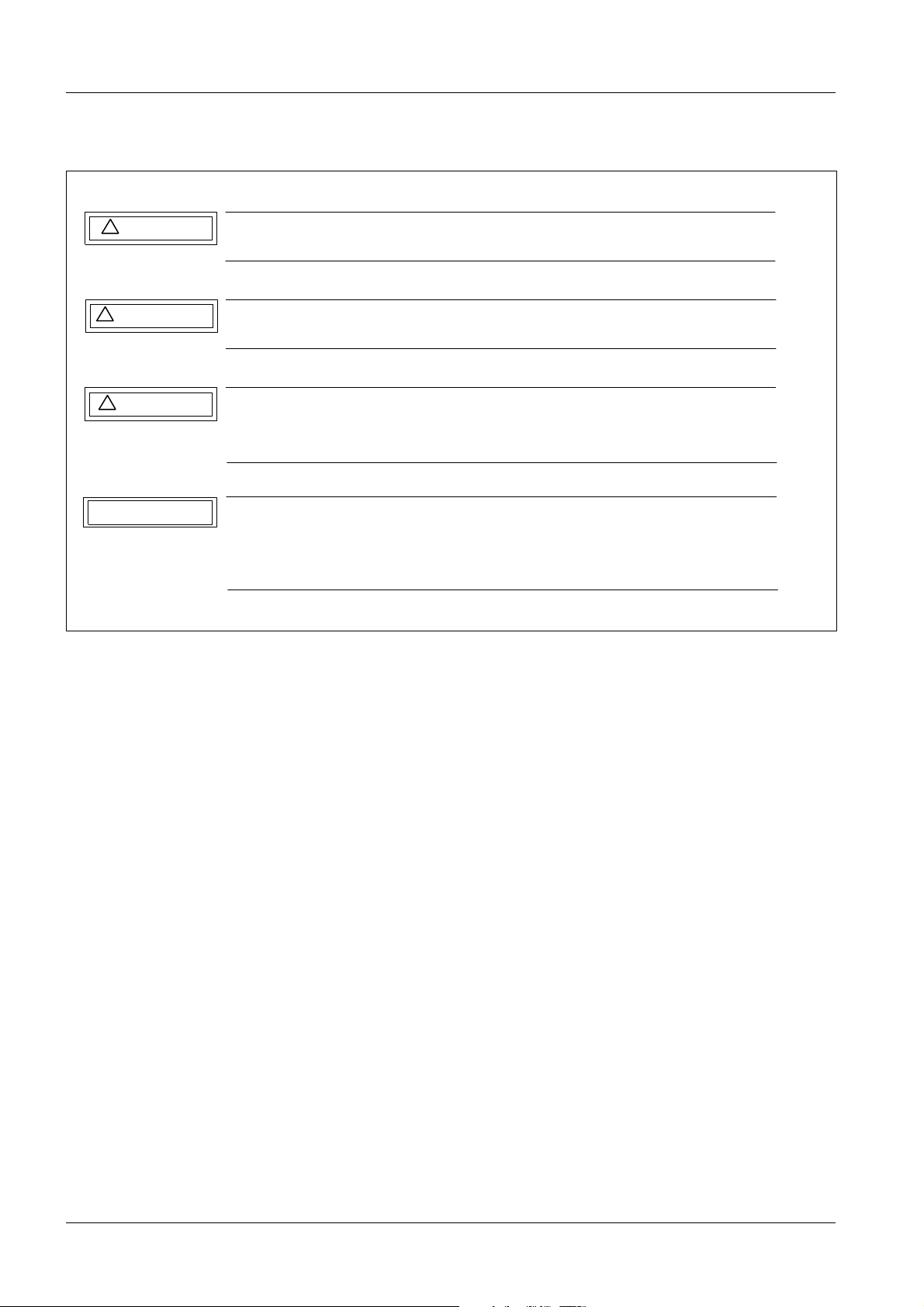
1.5 Emphasized texts
!
DANGER
!
WARNING
!
CAUTION
NOTICE
Fig. 1: Safety Notes
DANGER indicates when there is an immediate danger that
l e a d s to death or serious physical injury.
WARNING indicates a risk of danger that m a y l e a d to death
or serious physical injury.
CAUTION used with the safety alert symbol indicates a risk of
danger that leads to slight or moderate physical injury and/ or
damage to property.
NOTICE used without the safety alert symbol indicates a risk of
danger that if disregarded leads or may lead to a potential
situation which may result in an undesirable result or state other
than death, physical injury or property damage.
ARCADIS Varic SPR2-310.831.01.02.02 Siemens AG
08.04 CS SD 24
Page 8 of 24
Medical Solutions
Page 9

General 9
1.6 Safety information and preventive measures
NOTICE
The following instructions must be observed!
¹ When performing service work and tests, you must
adhere to:
¹ - The product-specific safety information in the docu-
mentation, safety information TD00-000.860.01.03.01,
¹ - As well as the general safety information contained in
ARTD, part 2.
¹ Pull out the power plug when working on the ARCADIS
Varic.
¹ Ensure compliance with general safety requirements
when working with the system under power.
¹ Observe ESD guidelines!
¹ Switch off the ARCADIS Varic before replacing modules
or boards.
¹ After all work has been completed and all cover panels
have been installed, perform the ground wire measurement according to ARTD-002.731.17.
¹ The protective conductor resistance may not exceed 0.2
ohms.
¹ When performing service work on the power-on module,
(replacing the power-on module or replacing the power
cable) the equivalent leakage current must be measured
and recorded.
Siemens AG SPR2-310.831.01.02.02 ARCADIS Varic
Medical Solutions
08.04 CS SD 24
Page 9 of 24
Page 10

10 General
1.7 Explanation of abbreviations
Abbrev. Explanation
SI Safety inspection
SIE Electrical safety inspection
SIM Mechanical safety inspection
PM Preventive maintenance
PMP Periodic preventive maintenance
PMA Preventive maintenance adjustments
PMF Preventive check of the operating values and functions
Q Quality quality, image quality
QIQ Image quality
QSQ System quality check
SW Software maintenance
The steps identified by these abbreviations are listed as checkpoints in the Maintenance
Protocol and must be checked off there accordingly.
NOTE
The sequence for the complete inspection and maintenance is
found on the following pages.
Each step must be performed annually, unless otherwise specified.
ARCADIS Varic SPR2-310.831.01.02.02 Siemens AG
08.04 CS SD 24
Page 10 of 24
Medical Solutions
Page 11

General 11
1.8 Maintenance interval
12 months
36 months
UPS (Uninterrupted Power Supply)
• The lead-acid batteries of the UPS in the monitor cart are to be exchanged every 36
months.
Siemens AG SPR2-310.831.01.02.02 ARCADIS Varic
Medical Solutions
08.04 CS SD 24
Page 11 of 24
Page 12

12 Visual and electrical inspection
2-
2 Visual and electrical inspection
2.1 Visual inspection
PMP Damage
Check the entire system for damage, such as housing or paint damage.
ARCADIS Varic SPR2-310.831.01.02.02 Siemens AG
08.04 CS SD 24
Page 12 of 24
Medical Solutions
Page 13

Visual and electrical inspection 13
2.2 Electrical inspection
2.2.1 Outlets
SIE Damage
SIE Line voltage
SIE Internal line impedance
• Check outlets used to operate the system for damage.
• Measure the line voltage and compare it to the line voltage label on the monitor cart.
• Measure the internal line impedance
Siemens AG SPR2-310.831.01.02.02 ARCADIS Varic
Medical Solutions
08.04 CS SD 24
Page 13 of 24
Page 14

14 Safety inspection
3-
3 Safety inspection
3.1 Mechanical safety inspection
SIM Cover panels
• Remove the cover panels from the ARCADIS Varic stand and the monitor cart.
• Check the cover panels for mechanical damage.
SIM Cable deflectors
• Check the cable deflectors at the stand and monitor cart and replace them if necessary.
SIM I.I. laser light localizer mechanics (if available)
• Check the I.I. laser light localizer for mechanical damage.
• Mount the I.I. laser light localizer on the I.I. and ensure proper locking and seating.
When doing this, pay special attention to the tension band and its closure.
• Check the I.I. ring for damage.
SIM I.I. laser light localizer function (if available)
• Perform maintenance on the I.I. laser light localizer according to Installation and Set-
ting Instructions RXR2-120.033.03...
SIM Laser light localizer mechanics (if available)
• Check the I.I. attachment of the laser light localizer for mechanical damage.
• Mount the I.I. attachment of the laser light localizer on the I.I. and ensure proper locking
and seating.
• Check the I.I. ring for damage.
SIM Laser light localizer function (if available)
• Perform maintenance on the laser light localizer according to Setting Instructions
RXR2-130.032.01...
SIM Foot brake
• Check the braking effect of the foot brakes of the ARCADIS Varic stand and monitor
cart on a flat surface.
SIM Brakes
• Use the spring balance to check whether the orbital brake, angulation brake, swivel
brake, horizontal lift brake, and vertical lift brake reach the defined braking values in the
braked state (Replacement of Parts Instructions for ARCADIS Varic).
SIM C-arm
• Perform all C-arm movements while paying attention to the bearing play and bearing
noises.
SIM Wheels
• Move ARCADIS Varic on a flat surface.
• Evaluate the straight and quiet movement of the ARCADIS Varic.
• Replace damaged wheels.
SIM Lifting column
ARCADIS Varic SPR2-310.831.01.02.02 Siemens AG
08.04 CS SD 24
Page 14 of 24
Medical Solutions
Page 15

Safety inspection 15
NOTE
There may not be any additional weight on the C-Arm for these
checks and adjustments, e.g. lead aprons or other cover panels.
• Switch the system on.
• Electrically move the lifting column over its entire lift range.
- While doing this, listen for movement noises and bearing play.
- The lifting column must automatically shut off at the final positions.
- In the case of the ARCADIS Varic, a stop signal sounds when moving backward and
the lifting column does not move. A signal sounds when the backward button is again
operated.
- When the direction buttons are pressed at the same time, the lifting column must remain in position.
• Operate the emergency stop button.
- The motorized vertical lift is blocked.
• Unlock the emergency stop button by pressing it lightly and turning to the left.
• Switch the system off.
• Oil the lifting column.
- Move the lifting column approx. 50 cm in an upward direction for this purpose.
- Remove the now visible plastic cap.
- Fill approx. 2 cm
SIM Cassette holder (if present)
3
of special oil into the visible tunnel.
• Check cassette holder for mechanical damage.
• Mount the cassette holder on the I.I. and ensure proper locking and seating.
SIM Warning signs
• Check the completeness and condition of the warning signs.
- If they are no longer legible, replace them.
SIM ID labels
• Check the completeness and condition of the ID labels.
- If they are no longer legible, replace them.
SIM TFT monitor(s)
• Check monitor(s) for damage.
• Check monitor(s) for proper attachment to the monitor cart.
• Check additional monitors for damage and proper attachment to the wall support/moni-
tor support system (if applicable).
Siemens AG SPR2-310.831.01.02.02 ARCADIS Varic
Medical Solutions
08.04 CS SD 24
Page 15 of 24
Page 16

16 Safety inspection
3.2 Electrical safety inspection
SIE Cables and plugs
• Check visible system cables and plugs for damage.
SIE Fluoroscopic timer
• Check: See compulsory radiation shut off.
SIE Acoustic warning signal
• Check: See compulsory radiation shut off.
SIE Compulsory radiation shut off
• Switch the system on.
X
SIE Check the radiation release switch
• Check the functioning of the acoustic warning signal and the compulsory radiation shut
off in accordance with the country regulations (if required). Also check the functioning of
the fluoroscopic timer in this process.
NOTE
The acoustic warning signal must sound every 4, 5.5, or 9.5 minutes of the fluoroscopic time depending on the programming. It
sounds again every 5 or 10 minutes. It is turned off by pressing the
-0- button once. Pressing this button again resets the fluoroscopic
timer to "0". Depending on the country-specific programming, either the required radiation shut off does not occur or it occurs every 5 or 10 minutes and then every 5 or 10 minutes after that.
• Check the functioning of the hand and foot switches for radiation release.
X
• check the cables of the radiation release switches for mechanical damage.
• Check the cables for cable breakage via movement.
SIE Radiation indicator
• Activate fluoroscopy briefly.
X ¹ The radiation indicator on the operating part of the ARCADIS Varic stand and
the radiation indicator on the monitor cart must light.
• Switch the system off.
SIE Iris collimator
• Check the iris collimator and correct it if necessary.
X - Select I.I. full format and activate fluoroscopy briefly.
- The collimator plates must be clearly visible at the image edge.
- Select zoom format and activate fluoroscopy briefly.
- The collimator plates must be slightly visible at the image edge.
SIE Conductive rubber
• Check conductive rubber on the ARCADIS Varic stand and the wheels of the monitor
cart for damage or contamination, and replace or clean them as necessary.
SIE Ground wire test
• Test the ground wire with the ground wire tester according to ARTD-002.731.17.
ARCADIS Varic SPR2-310.831.01.02.02 Siemens AG
08.04 CS SD 24
Page 16 of 24
Medical Solutions
Page 17

Safety inspection 17
NOTE
The equivalent leakage current is to be measured and documented
using the equivalent leakage current tester according to
ARTD-002.731.17 in the scope of validity of DIN VDE 0751. See the
subsequent work steps.
SIE Equivalent leakage current
The equivalent leakage current is to be measured and documented using the equivalent
leakage current tester according to ARTD-002.731.17 in the scope of validity of DIN VDE
0751.
NOTE
The instructions according to ARTD-002.731.17 are to be adhered
to outside the scope of validity of DIN VDE 0751.
Siemens AG SPR2-310.831.01.02.02 ARCADIS Varic
Medical Solutions
08.04 CS SD 24
Page 17 of 24
Page 18

18Maintenance, operating value, and functional inspection
4-
4 Maintenance, operating value, and functional inspection
4.1 Maintenance
PMP Cleaning the system
• Clean the entire system:
- Visible cables
- Outside surfaces
- Running surfaces of the wheels
- Interior space
PMP System ventilation
• Clean the ventilation slots of the ARCADIS Varic stand and monitor cart.
ARCADIS Varic SPR2-310.831.01.02.02 Siemens AG
08.04 CS SD 24
Page 18 of 24
Medical Solutions
Page 19

Maintenance, operating value, and functional inspection
4.2 Operating value inspection
SIE Dose rate
X
• Switch the system on.
• Check the dose rate (see the ARCADIS Varic service instructions for this purpose).
PMF Event log
• Read out and evaluate the system event log.
Siemens AG SPR2-310.831.01.02.02 ARCADIS Varic
Medical Solutions
08.04 CS SD 24
Page 19 of 24
Page 20

20Maintenance, operating value, and functional inspection
4.3 Functional inspection
SIE TFT monitor
• Check the TFT monitor with the image quality assurance test.
SIE Cassette exposure collimation (if present)
• Check cassette exposure collimation.
X - Attach the cassette holder with the cassette and film to the I.I.
- The iris diaphragm opens fully when the cassette is inserted.
- The mA display switches to mAs in the exposure data field and the operation indicator switches off.
- Initiate an exposure with 40 kV and 5 mAs and develop the film. The diaphragm
plates should be visualized parallel to the film edges, be visible at all four edges of the
film, and appear at the film edge.
- Pressing the iris diaphragm buttons simultaneously causes the iris diaphragm to
open to the dimensions previously set during fluoroscopy.
• Correction:
- See the Main System Adjustment Instructions, "Setting the cassette exposure collimation".
SIE Area dose product measuring unit (if present)
• Check the area dose product measuring unit and the calibration. (See the Main System
Adjustment Instructions SPR2-310.842.01...).
PMF Laser camera connection (if present)
• Check the functioning of the laser camera connection.
PMF Check the operating function.
• Check all system operating functions.
PMF Monitor display of the iris collimator opening
• Select I.I. full format.
• Completely close the iris collimator (X-iris).
• Mark the diameter of the collimated iris collimator opening on the monitor.
X
• Switch fluoroscopy on briefly. The actual diameter of the iris collimator is visible. The
previously displayed monitor display must match the position and diameter of the actual iris collimator opening.
• Completely open the iris collimator.
• Mark the diameter of the collimated iris collimator opening on the monitor.
X
• Switch fluoroscopy on briefly. The actual diameter of the iris collimator is visible. The
previously displayed monitor display must match the position and diameter of the actual iris collimator opening.
• Select I.I. zoom format.
• Completely close the iris collimator (X-iris).
• Mark the diameter of the collimated iris collimator opening on the monitor.
ARCADIS Varic SPR2-310.831.01.02.02 Siemens AG
08.04 CS SD 24
Page 20 of 24
Medical Solutions
Page 21

Maintenance, operating value, and functional inspection
X • Switch fluoroscopy on briefly.
The actual diameter of the iris collimator is visible. The previously displayed monitor
display must match the position and diameter of the actual iris collimator opening.
• Completely open the iris collimator.
• Mark the diameter of the collimated iris collimator opening on the monitor.
X
PMF PMF monitor display of the slot diaphragm positions.
• Switch fluoroscopy on briefly.
The actual diameter of the iris collimator is visible. The previously displayed monitor
display must match the position and diameter of the actual iris collimator opening.
• Select I.I. full format.
• Completely close the slot diaphragm and rotate the slot diaphragm from the basic posi-
tion.
• Mark the distance and angle of rotation of the displayed slot diaphragm position on the
monitor.
X
• Switch fluoroscopy on briefly.
The actual position (distance of the plates and angle of rotation) of the slot diaphragm is
visible. The previously displayed monitor display must match the position and angle of
rotation of the actual slot diaphragm position.
• Completely open the slot diaphragm and rotate the slot diaphragm again.
• Mark the distance and angle of rotation of the displayed slot diaphragm position on the
monitor.
X
• Switch fluoroscopy on briefly.
The actual position (distance of the plates and angle of rotation) of the slot diaphragm is
visible. The previously displayed monitor display must match the position and angle of
rotation of the actual slot diaphragm position.
X
• Select I.I. zoom format.
• Completely close the slot diaphragm and rotate the slot diaphragm from the basic posi-
tion.
• Mark the distance and angle of rotation of the displayed slot diaphragm position on the
monitor.
• Switch fluoroscopy on briefly.
The actual position (distance of the plates and angle of rotation) of the slot diaphragm is
visible.
• The previously displayed monitor display must match the position and angle of rotation
of the actual slot diaphragm position.
• Completely open the slot diaphragm and rotate the slot diaphragm again.
• Mark the distance and angle of rotation of the displayed slot diaphragm position on the
monitor.
Siemens AG SPR2-310.831.01.02.02 ARCADIS Varic
Medical Solutions
08.04 CS SD 24
Page 21 of 24
Page 22

22Maintenance, operating value, and functional inspection
X • Switch fluoroscopy on briefly.
The actual position (distance of the plates and angle of rotation) of the slot diaphragm is
visible. The previously displayed monitor display must match the position and angle of
rotation of the actual slot diaphragm position.
NOTE
Perform this check with the lowest possible kV values so that the
front edges of the slot diaphragm plate are effectively visualized.
PMF Battery replacement in the UPS
The lead-acid battery installed in the UPS must be replaced preventively every 36
months.
The replacement procedure is described in the supplied installation instructions from the
manufacturer as well as in Replacement of Parts Instructions SPR2-310.841.01.
ARCADIS Varic SPR2-310.831.01.02.02 Siemens AG
08.04 CS SD 24
Page 22 of 24
Medical Solutions
Page 23

Final result/quality inspection and maintenance 23
5-
5 Final result/quality inspection and maintenance
SIE IQ quick test
• Test the image quality according to the ARCADIS Varic image quality assurance test.
Include additional monitors (if applicable).
PMP Maintenance
• Entire system: Improve damage to paint as possible.
Siemens AG SPR2-310.831.01.02.02 ARCADIS Varic
Medical Solutions
08.04 CS SD 24
Page 23 of 24
Page 24

24 Final result/quality inspection and maintenance
5.1 Final work steps
SIE Ground wire test
SIE Ground wire resistance
• Perform the ground wire test while the system is closed according to
ARTD-002.731.17. The ground wire resistance may not exceed 0.2 ohms.
ARCADIS Varic SPR2-310.831.01.02.02 Siemens AG
08.04 CS SD 24
Page 24 of 24
Medical Solutions
 Loading...