

Page 1
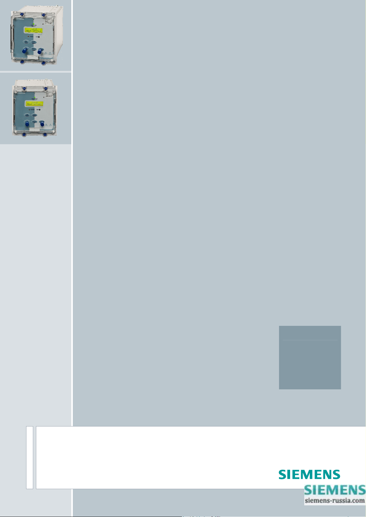
7SG11 – Argus 8
Voltage and Frequency Relays
Answers for energy
Reyrolle
Protection
Devices
Page 2

Contents
Technical Manual Chapters
1 Description of Operation
2 Performance Specification
3 Relay Settings
4 Communication Interface
5 Applications Guide
6 Installation
7 Commissioning
8 Maintenance
9 Drawings
7SG11 Argus 8 Contents
The copyright and other intellectual property rights in this document, and in any model or article produced from it
(and including any registered or unregistered design rights) are the property of Siemens Protection Devices
Limited. No part of this document shall be reproduced or modified or stored in another form, in any data retrieval
system, without the permission of Siemens Protection Devices Limited, nor shall any model or article be
reproduced from this document unless Siemens Protection Devices Limited consent.
While the information and guidance given in this document is believed to be correct, no liability shall be accepted
for any loss or damage caused by any error or omission, whether such error or omission is the result of
negligence or any other cause. Any and all such liability is disclaimed.
©2011 Siemens Protection Devices Limited
Page 3
7SG11 Argus 8 Description of Operation
7SG11 Argus 8
Voltage and Frequency Relays
Document Release History
This document is issue 2010/02 The list of revisions up to and including this issue is:
Pre release
2010/02 Document reformat due to rebrand
Software Revision History
2011/11 2422H80004R7 Fault trigger when the voltage blocking threshold is OFF.
IEC 60870-5-103 fault numbering for fault and its measurands
The copyright and other intellectual property rights in this document, and in any model or article produced from it
(and including any registered or unregistered design rights) are the property of Siemens Protection Devices
Limited. No part of this document shall be reproduced or modified or stored in another form, in any data retrieval
system, without the permission of Siemens Protection Devices Limited, nor shall any model or article be
reproduced from this document unless Siemens Protection Devices Limited consent.
While the information and guidance given in this document is believed to be correct, no liability shall be accepted
for any loss or damage caused by any error or omission, whether such error or omission is the result of
negligence or any other cause. Any and all such liability is disclaimed.
©2011 Siemens Protection Devices Limited
Page 4

7SG11 Argus 8 Description of Operation
Contents
1 Introduction..........................................................................................................................................4
3 Protection Functions....................................................................................................................8
3.1 Voltage Blocking Element............................................................................................................8
3.2 Voltage Elements ........................................................................................................................8
3.3 NPS Overvoltage Elements.........................................................................................................9
3.4 NVD Overvoltage Elements.........................................................................................................9
3.5 Frequency Elements....................................................................................................................9
3.6 Two Systems Connection..........................................................................................................10
3.7 External Tripping .......................................................................................................................10
4 Other Features ..........................................................................................................................10
4.1 Metering.....................................................................................................................................10
4.2 Data Storage .............................................................................................................................11
4.2.1 Waveform Records..........................................................................................................11
4.2.2 Event Records.................................................................................................................11
4.2.3 Fault Data Records .........................................................................................................12
4.3 Communications........................................................................................................................12
4.4 General Alarm Screens.............................................................................................................13
4.5 Default Instrument Screens.......................................................................................................13
4.6 Multiple Settings Groups. ..........................................................................................................13
4.7 Password Feature .....................................................................................................................13
4.8 Trip Circuit Supervision .............................................................................................................14
5 User Interface............................................................................................................................14
5.1 Liquid Crystal Display................................................................................................................14
5.2 LED Indications .........................................................................................................................14
5.3 Keypad.......................................................................................................................................14
5.4 Navigating the Menu System.....................................................................................................14
Table of Figures
Figure 1 - Voltage Element.......................................................................................................................8
Figure 2 - NPS Overvoltage Element.......................................................................................................9
Figure 3 - NVD Overvoltage Element.......................................................................................................9
Figure 4 - Frequency Element................................................................................................................10
Figure 5 - Display Menu Structure..........................................................................................................20
Tables
Table 1 - Argus 8 - 2 Pole Variants...........................................................................................................................5
Table 2 - Argus 8 - 3 Pole Variants...........................................................................................................................5
Table 3 - Output Relay Types...................................................................................................................................6
Table 4 - Connection Table (E4 Versions)..............................................................................................................16
Table 5 - Connection Table (E6 Versions)..............................................................................................................17
Table 6 - Event Codes ............................................................................................................................................19
©2011 Siemens Protection Devices Limited Chapter 1 Page 2 of 20
Page 5

7SG11 Argus 8 Description of Operation
Reference Material
[1] - REYDISP EVOLUTION : is a PC based relay support package which allows local or remote access to relays
for uploading settings, downloading event and disturbance records, readin g real-time data and allowing control of
plant. The package is available from Reyrolle Protection and is compatible with all Argus range relays.
[2] - INFORMATIVE COMMUNICATIONS INTERFACE : a report detailing all aspects of the communications
protocol used in the Argus range of relays is available from Reyrolle Protection. The report reference is
434TM05B.
©2011 Siemens Protection Devices Limited Chapter 1 Page 3 of 20
Page 6

7SG11 Argus 8 Description of Operation
1 Introduction
The Argus 8 series of Voltage and Frequency relays are numerical, multi-function devices, which have been
designed to be applied for the protection of generation, transmission, distribution and industrial systems.
• Argus 8 - 100 series provide under / over voltage, negative sequence overvoltage and ne utral voltage
displacement functions.
• Argus 8 - 200 series provide under / over frequency functions in addition to the functions included in the
100 series.
• Argus 8 - 300 series provide identical functionality to the 200 series but have a faster frequency element
operate time. Suitable for 50Hz systems only.
The protection functions available in the range have many possible applications, some of which are mentioned
below :
Under / overvoltage elements :
Four independent elements are supplied, each of which can be set to operate for under or overvoltage conditions
and all having separate DTL time delay elements. These can be used to protect generators against overvoltages,
motors against loss of supply or applied as backup protection in the event of defective system regulatin g
equipment.
Negative phase sequence (NPS) overvoltage elements :
Two independent elements are supplied, each of which has a DTL time delay element. These can be used to
monitor the quality of the supply and protect plant or feeders against system unbalance.
Neutral voltage displacement (NVD) elements :
Two independent elements are supplied, each of which has a DTL time delay element. These can be used to
detect earth faults in high impedance earthed or isolated systems. For this feature, the residual voltage can be
measured directly from an open delta tertiary winding or calculated interna lly from the three phase voltage inputs.
The NVD elements include a third harmonic filter, which de-sensitises the elements to any superimposed third
harmonic frequencies.
Under / overfrequency elements :
Four independent elements are supplied, each of which can be set to operate for under or over frequenc y and all
having separate DTL time delay elements. These can be applied wherever frequency protection is required to
maintain system stability e.g. in load shedding schemes. The accuracy and security of operation of the numeric
algorithms enables the relay to be employed to detect any frequency abnormalities.
Blocking operation :
Each protection element can be blocked from operation by a user defined status input signal. In addition, the
voltage, frequency, and NPS elements can be blocked by the Voltage Blocking Threshold, which has a variable
setting range. Also, each frequency element can be blocked by any combination of the voltage elements starting.
Argus 8 series of Voltage and Frequency relays are part of the comprehensive range of Argus-platform based
numeric relays. These relays have extensive control functions, which are suppleme nted by advanced metering,
data storage and fibre optic communications. Supervisory and self-monitoring features give added confidence to
the user as well as reduced maintenance and down time. A menu-based interface gives user-friendly access to
relay settings, meters and operational data.
The relay conforms to the relevant IEC 60255 standards.
©2011 Siemens Protection Devices Limited Chapter 1 Page 4 of 20
Page 7
7SG11 Argus 8 Description of Operation
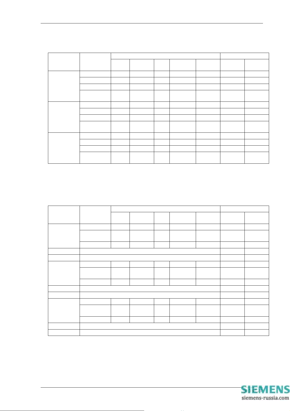
The following table details the functions available in the Argus 8 - two pole variants which are supplied in the
Epsilon E4 case size. Note how the number and type of elements included depend upon the ‘C onnection Setting’
parameter.
Connection
Number
AG8 101-103
AG8 201-203
AG8 301303*
* Argus 8 types 301-303 are suitable for 50Hz systems only.
The following table details the functions available in the Argus 8 - three pole variants which are suppli ed in the
Epsilon E6 case size. Note how the number and type of elements included depend upon the ‘C onnection Setting’
parameter.
Setting
2Ph-Ph 4 - 2 - - 4 7
Ph-N+NVD 4 - - 2 -
Ph-Ph+NVD 4 - - 2 -
2 systems
A/B
2Ph-Ph 4 4 2 - - 4 7
Ph-N+NVD 4 4 - 2 -
Ph-Ph+NVD 4 4 - 2 -
2 systems
A/B
2Ph-Ph 4 4 2 - - 4 7
Ph-N+NVD 4 4 - 2 -
Ph-Ph+NVD 4 4 - 2 -
2 systems
A/B
Voltage Frequency NPS NVD
4 - - - -
4 - - - -
4 - - - -
Table 1 - Argus 8 - 2 Pole Variants
Protection Elements Available I/O Available Catalogue
Direct
NVD
Calc.
Inputs Outputs
Catalogue
Number
AG8 104-106
AG8 107-109 All features as above 9 7
AG8 110-112 All features as above 5 11
AG8 204-206
AG8 207-209 All features as above 9 7
AG8 210-212 All features as above 5 11
AG8 304-
306*
AG8 307-309 All features as above 9 7
AG8 310-312 All features as above 5 11
* Argus 8 types 304-312 are suitable for 50Hz systems only.
Connection
Setting
3Ph-Ph 4 - 2 - - 1 7
2Ph-
Ph+NVD
3Ph-N+NVD 4 - 2 - 2
3Ph-Ph 4 4 2 - - 1 7
2Ph-
Ph+NVD
3Ph-N+NVD 4 4 2 - 2
3Ph-Ph 4 4 2 - - 1 7
2Ph-
Ph+NVD
3Ph-N+NVD 4 4 2 - 2
Voltage Frequency NPS NVD
4 - - 2 -
4 4 - 2 -
4 4 - 2 -
Table 2 - Argus 8 - 3 Pole Variants
Protection Elements Available I/O Available
Direct
NVD
Calc.
Inputs Outputs
©2011 Siemens Protection Devices Limited Chapter 1 Page 5 of 20
Page 8
7SG11 Argus 8 Description of Operation
2 Hardware Description
2.1 General
All of the Argus range of relays share common hardware components and modules. The design for the
mechanical arrangement of the relays has been carefully cho sen to provide a high level of EMI
screening using multi-layer PCB’s with ground planes, RFI suppression components and earthed
metal screens. The internal arrangement has been divided into noisy and quiet areas in order to
improve noise immunity and reduce RFI emissions. The only direct connection from the quiet
components to the external environment is via the optical serial communications interface, which is
immune to radiated or conducted interference.
2.2 Analogue Inputs
The input stage of an Argus 8 relay measures either two or three voltage quantities depending upon the particular
variant. Over the range of 5 Vrms to 200 Vrms it maintains accuracy within ±1% (or 0.25V) over the declared
frequency performance range. The wide measuring range of the input stage allows for either phase-phase or
phase-neutral connections e.g. 110Vrms or 63.5Vrms nominal voltages.
Note : on relay variants which have a 2Ph-Ph connection setting, the 3rd phase voltage can be calculated from the
two known phases if the external connection is connected phase-phase.
In order to ensure high accuracy voltage, frequency and sequence component calculations the voltage
signals are sampled at 32 samples per cycle for both 50Hz and 60Hz system frequencies. The high
sampling rate provides high accuracy and quality waveform storage records, which are stored at a rate
of 16 samples per cycle.
2.3 Output Relays
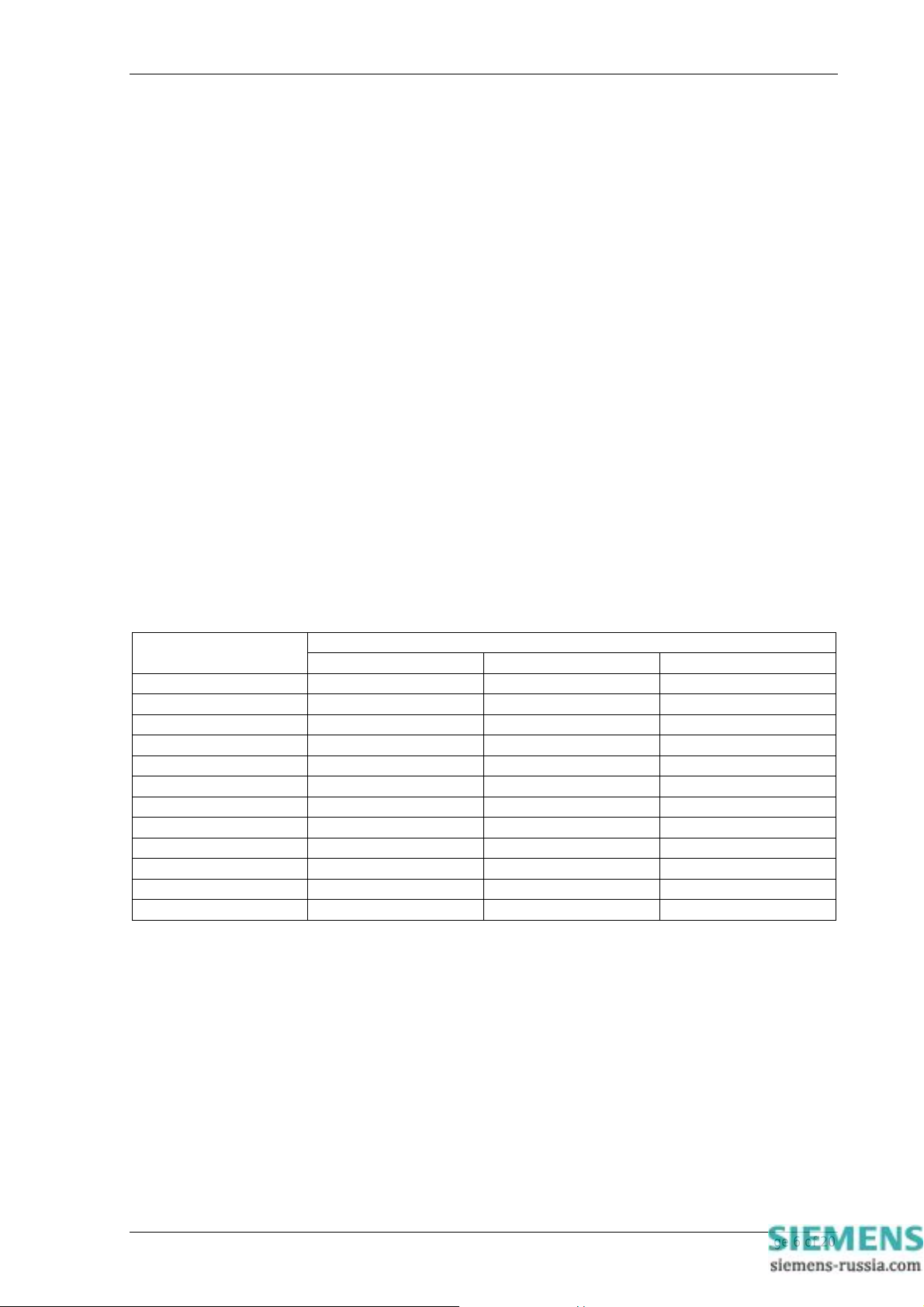
Argus 8 relays have a variety of output contact types available depending upon the case size and expansion card
option. The full range is given in Table 3.
Catalogue Number
C/O Contact N/O Contact N/C Contact
AG8 101-103 1 5 1
AG8 201-203 1 5 1
AG8 301-303 1 5 1
AG8 104-106 3 4 AG8 204-206 3 4 AG8 304-306 3 4 AG8 107-109 3 4 AG8 207-209 3 4 AG8 307-309 3 4 AG8 110-112 3 8 AG8 210-212 3 8 AG8 310-312 3 8 -
Table 3 - Output Relay Types
All output relays are fully user configurable and can be programmed to operate from any or all of the protection
functions. In addition, a watchdog feature within the relay can be mapped to any of the output relays. A
changeover or normally-closed contact is generally required for this.
All output relays are of the same design and therefore each is capable of handling direct circuit breaker-tripping
duty.
Output relays can be set to remain energised for a minimum time of between 100-500msec. If required, however,
outputs can be programmed to operate as latching relays. These latched outputs can be reset by either pressing
the TEST/RESET button, by energising a status input or by sending an appropriate communications command.
A trip test feature is provided to exercise the output contacts.
Output Relays Available
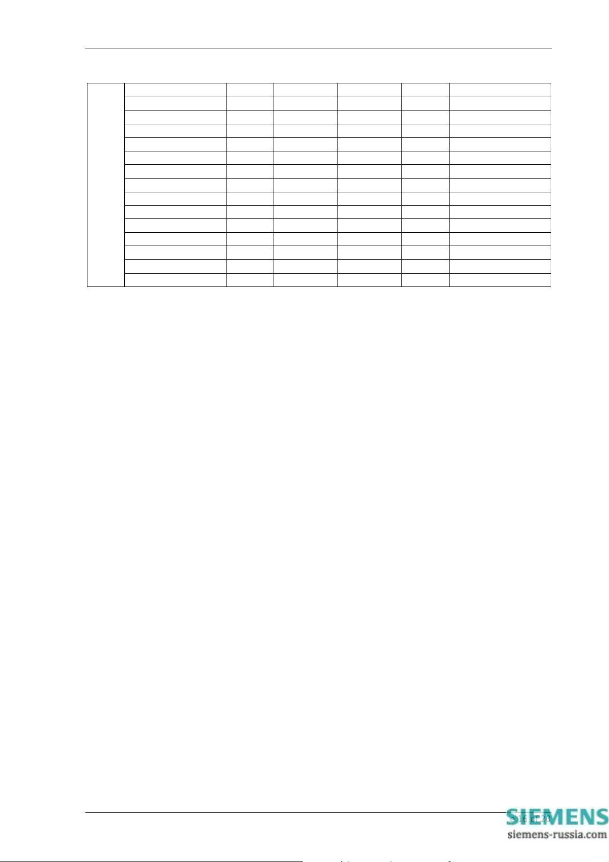
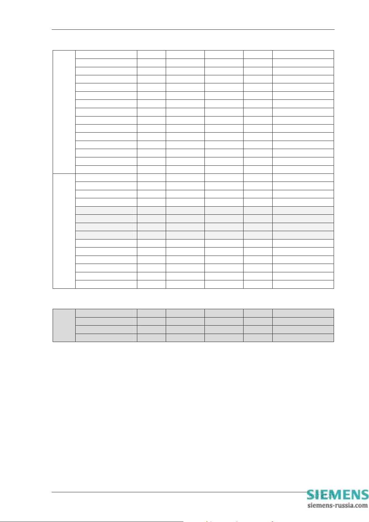
For a list of terminal numbers and their usage see Tables 4 and 5 at the back of this section.
©2011 Siemens Protection Devices Limited Chapter 1 Page 6 of 20
Page 9

7SG11 Argus 8 Description of Operation
2.4 Status Inputs
On two pole Argus 8 variants there are a total of 4 status inputs available in the relay. Of these three have a
common negative supply and one is electrically isolated from the rest.
Standard three pole Argus 8 relays have 1 status input. One type of expansion card includes an extra 4 status
inputs giving a total of 5. Another type of expansion card includes an extra 8 status inputs giving a total of 9.
Tables 1 and 2 show the number of status inputs available for each type of relay.
All status inputs are fully user programmable and each has a pick-up and drop-off timer. These timers allow
software filtering to be applied, which provides security in the presence of any induced A.C. voltages in the
external wiring. If high-speed operation is required then the pick-up delay should be set to zero.
Each of the status inputs can be programmed to perform one of the following functions :
• Inhibit operation of any one or more protection functions.
• Select an alternative settings group.
• T r igger storage of a waveform record.
• S ynchronise th e real-time clock.
• Reset latched output relays.
• Energise a n ou tput relay.
• Regist er a Trip by an external device.
• Raise an alarm annunciation.
Additionally, each status input can have its operating logic inverted with the Status Invert feature.
For a list of terminal numbers and their usage see Tables 4 and 5 at the back of this section.
2.5 Self Monitoring
The relay incorporates a number of self-monitoring features. Each of these features can initiate a controlled reset
sequence, which can be used to generate an alarm output. In addition, the Protection Healthy LED will give visual
indication.
A watchdog timer continuously monitors the microprocessor and the relay program memory is continuously
checked for data corruption using a cyclic redundancy check (CRC) routine. The internal voltage supply rails are
also continuously supervised and the microprocessor is reset if any of the rails are detected to be outside of their
working ranges. Any failure is detected in sufficient time so that the microprocessor can be shut down in a safe
and controlled manner.
2.6 Measuring Principles
The input phase voltages to the relay are passed through voltage transformers, which step down the phase
voltages to levels which are suitable for the electronic input stage of the relay. The transformers also provide
essential isolation between the power system and the relay. The output of the transformers are differential signals
which are passed through lowpass filters and then from the voltage transformer board to the processor / analog ue
board. Here the signals are fed to differential amplifiers which have excellent common-mode rejection. T hese will
reject any high frequency noise which may have coupled to the differential pair signals.
The single-ended output from the differential amplifiers is then fed to gain switching amplifiers which maximise the
signal gain to provide optimum measurement resolution. From here the signals are fed to the ADC where they are
sampled at a rate of 32 samples per power system cycle. (The dynamic range of the analogue-to-digital converter
(ADC) is increased with this gain switching method.)
The main signal processing algorithm in the relay is a discrete fourier transform (DFT ) which is performed on each
phase input. The DFT extracts the power system fundamental frequency component from the input voltages,
effectively filtering out noise, D.C. and harmonics. The DFT is tuned for either 50 or 60Hz, depending upon the
system frequency setting. Output from the DFT calculations are real and imaginary components for ea ch voltage
input.
The real and imaginary components are used to derive the magnitude quantity, which is then scaled to give a
RMS value. Part of the DFT calculation includes extra filtering which smoothes the real and imaginary
components, giving reduced ripple on the RMS calculation for off-system frequency conditions. In addition, a
lookup table is used to compensate for magnitude variations from the output of the RMS calculation for 4 7-62Hz
frequencies.
The real and imaginary components output from the DFT module are als o used to derive the phase of the input
signal. The frequency is derived from the rate-of-change of the phase angle calculation. In addition, negative
phase sequence (NPS) and zero phase sequence (ZPS) quantities are also derived from the output of the DFT
calculation. The DFT ensures that D.C. and harmonics are rejected and so guarantees accurate and stable
©2011 Siemens Protection Devices Limited Chapter 1 Page 7 of 20
Page 10
7SG11 Argus 8 Description of Operation
sequence calculations. The ZPS calculation, which is used in the ne utral voltage displacement (NVD) function
also benefits from excellent inherent 3
rd
harmonic rejection.
All relays are fully calibrated during manufacture usin g accurate voltage source equipment. Calibration
coefficients are stored in EEPROM and are used by the processor to compensate for any inaccuracies in the
input stage, which have been introduced by the analogue circuits. Errors in magnitude and phase are eliminated
using this method.
3 Protection Functions
3.1 Voltage Blocking Element
The voltage blocking element acts as a block to the Voltage, Frequency and NPS elements in the relay. If all
phase voltages fall below the threshold level then the blocking operation will operate. This block does not apply to
the NVD elements.
• For 3 pole relay variants: Voltage blocking is applied when all 3 phases fall below the threshold level. (If
set to 2Ph-Ph+NVD, then when the two phases fall below).
• For 2 pole relay variants (set as 2Ph-Ph): Voltage blocking is applied when both phases fall below the
threshold level.
The setting range for the voltage blocking threshold is OFF, 1V - 100V with a 1V step . This element is required
mainly for undervoltage operation conditions. Under normal circumstances, if all phase voltages fall below the
undervoltage setting, a trip output would be the expected response. However, in some applications e.g. autoreclose schemes, having an undervoltage relay trip when the line is de-ener gised during the auto-reclose
sequence is not usually desirable. Blocking the undervoltage operation in this situatio n can be achieved by using
the Voltage Blocking Threshold, which should generally be set above the level of expected induced voltages on
the line.
(See Applications Guide Section 2.2 for more information regarding this element).
3.2 Voltage Elements
Each version of the Argus 8 relay has 4 voltage elements as standard. These can be configured to be either
undervoltage (U/V) or overvoltage (O/V) elements. If the input voltages exceed the pickup level, whether U/V or
O/V, then each element operates through a gate, which selects operation from any one phase or all phases. At
this point the element can still be inhibited from starting, using either a status input inhibit or if the input voltages
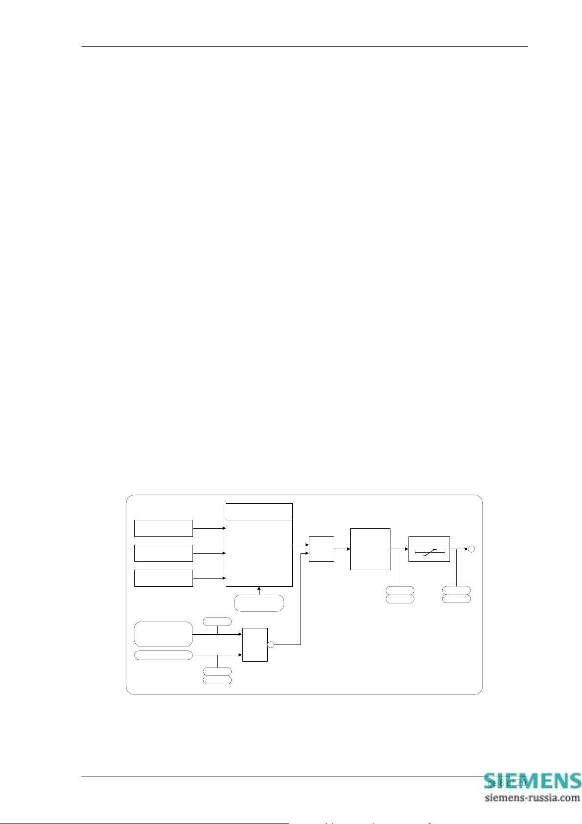
are below the voltage blocking threshold level. Figure 1 shows the basic operation of each voltage element. The
‘event’ and ‘instrument’ labels in the diagram indicate where this type of information is generated.
V Element O/P Phases
VA Pickup Value
VB Pickup Value
VC Pickup Value
(VA & VB & VC)
☯
V Block Threshold
Status Input
Event
(V Element Inhibit)
Event
Instrument
Any 1
or
All
Setting Select
1
Block
&
V Element
Starter
Instrument
DTL
Event
Trip
Event
Instrument
Figure 1 - Voltage Element
The voltage elements each have a variable hysteresis setting which allows the user to vary the pick-up - drop-off
ratio for a particular element.
©2011 Siemens Protection Devices Limited Chapter 1 Page 8 of 20
Page 11
7SG11 Argus 8 Description of Operation
3.3 NPS Overvoltage Elements
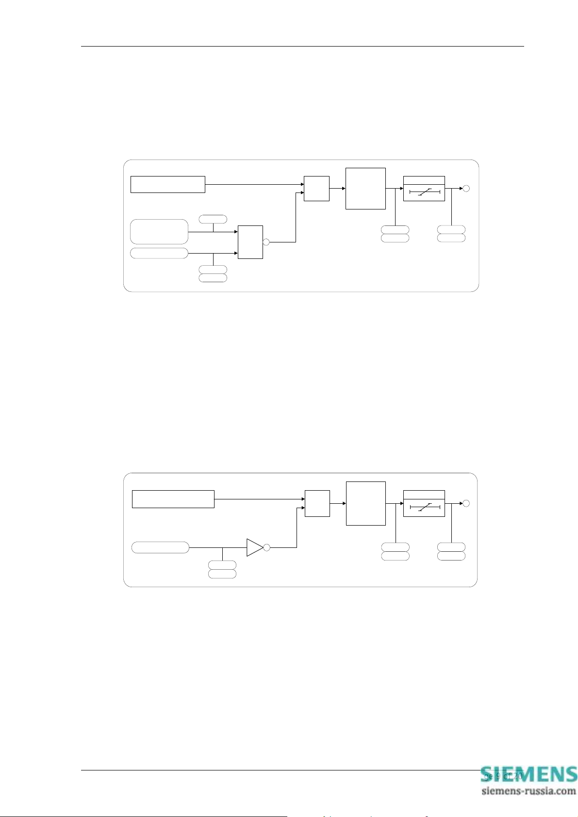
Some Argus 8 variants have, depending upon their configuration, 2 NPS overvoltage elements. If the NPS (V2)
input exceeds the setting value the starter will pickup unless any of the inhibits are enable d. Figure 2 shows the
basic operation of each NPS overvoltage element. The ‘event’ and ‘instrument’ labels in the dia gram indicate
where this type of information is generated.
NPS (V2) Pickup Value
(VA & VB & VC)
☯
V Block Threshold
Status Input
(V2 Element Inhibit)
Event
Event
Instrument
1
Block
NPS
&
Element
Starter
Instrument
Event
DTL
Trip
Event
Instrument
Figure 2 - NPS Overvoltage Element
3.4 NVD Overvoltage Elements
Some Argus 8 variants have, depending upon configuration, 2 neutral voltage displacement (NVD) overvoltage
elements. The neutral or residual voltage can be measured directly from an open delta tertiary windin g or
calculated internally from the three phase voltage inputs.
If the relay is configured so that the residual voltage is measured directly, then this value is fed to the element
starter directly. Also, a 3Vo V.T. ratio setting will be made available. If however, the residual is calculated from the
3 phase input voltages, then 3 x Vo is fed to the element starter. (Vo is the zero sequence voltage ).
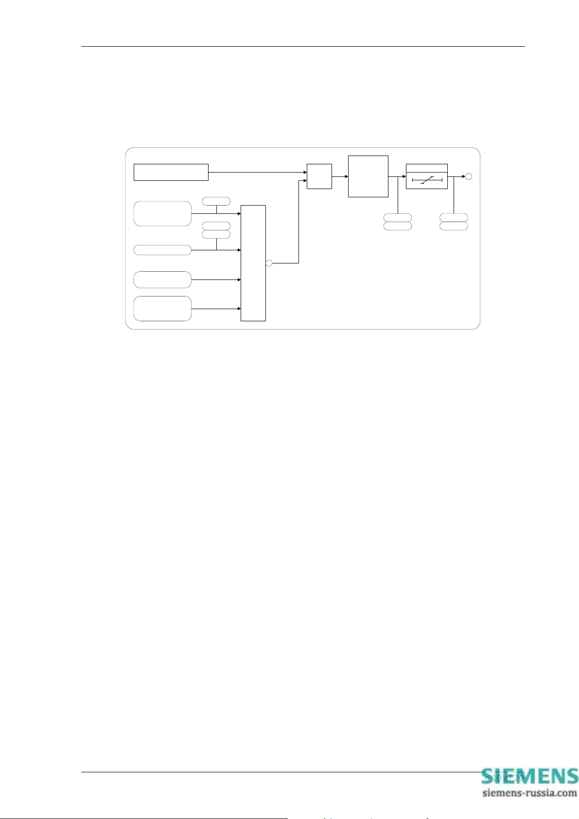
If the NVD input exceeds the setting value the starter will pickup unless an inhibit is enabled. Figure 3 sh ows the
basic operation of each NVD overvoltage element. The ‘event’ and ‘instrument’ labels in the diagram indicate
where this type of information is generated.
3 x ZPS (3Vo) Pickup Value
Status Input
Event
Instrument
NVD
&
Block(3Vo Element Inhibit)
Element
Starter
Instrument
Event
DTL
Trip
Event
Instrument
Figure 3 - NVD Overvoltage Element
3.5 Frequency Elements
Argus 8 - 200 and 300 series variants have 4 frequency elements as standard. These can be configured as either
underfrequency (U/F) or overfrequency (O/F). Each element can be inhibited in four different ways :-
1. If all phase voltages fall below the voltage blocking threshold level.
2. Via a status input inhibit signal.
3. Via any combination of voltage elements starting.
©2011 Siemens Protection Devices Limited Chapter 1 Page 9 of 20
Page 12
7SG11 Argus 8 Description of Operation
4. If all of the phase voltages fall below 29V. This is independent of the voltage blocking threshold and
is required to ensure that the frequency accuracy claims are within ±10mHz. (Below 29V the
frequency accuracy deteriorates marginally).
Figure 4 shows the basic operation of the frequency elements. The ‘event’ and ‘instrumen t ’ labels in the diagram
indicate where this type of information is generated.
F Element Pickup Value
(VA & VB & VC)
☯
V Block Threshold
Status Input
V Element Inhibit
(VA & VB & VC)
☯
29Vrms
(F Element Inhibit)
Event
Instrument
Event
1
Block
Frequency
&
Element
Starter
Instrument
Event
DTL
Trip
Event
Instrument
Figure 4 - Frequency Element
The frequency calculation is performed on data from one input phase only. If all phase voltages are above an
internal threshold of 29V, then the frequency calculation will be derived from the phase A input. If however, phase
A falls below 29V, then the calculation will automatically switch to phase B data. During the switchov er process
the last frequency value measured is held until phase B returns a valid frequency answer. This will take
approximately 180ms. The switchover precedence is A-B-C and as each phase recovers its voltage then the
frequency calculation is switched back to this phase. This method ensures that the frequency calc ulation is
performed on a solid system voltage and not on low levels of input voltage where noise co uld cause incorrect
calculation.
3.6 Two Systems Connection
Two pole Argus 8 variants have a ‘2 Systems A/B’ connection setting. This setting re-configures the relay to
become a 4 element voltage relay but with the ability to assign the voltage elements to two different systems.
System A has voltage elements VE1 and VE2 assigned to it and System B has VE3 and VE4 assigned to it.
The System A input voltage is applied at the Va / Vab input terminals. System B is applied at the Vo / Vbc input
terminals.
3.7 External Tripping
Any status input can be programmed to receive a trip signal from another device. The status input should firstly be
mapped to the trip output contact in the Output Configuration Menu, so that energisation of the status input results
in a trip signal being issued. If the same trip contact is specified in the ‘Fault trigger’ setting then the relay will
switch to the fault data mode and indicate that an external trip has occurred.
4 Other Features
4.1 Metering
The Argus metering feature provides real-time data available from the relay fascia in the ‘ Instruments Mode’ or via
the communications interface. The following displays are available :
• Primary RMS volts for VA, VB, VC and VO (alternatively VAB, VBC, VCA)
• Secondary RMS volts for Va, Vb, Vc, V1, V2 and Vo (alternatively Vab, Vbc, Vca)
©2011 Siemens Protection Devices Limited Chapter 1 Page 10 of 20
Page 13

7SG11 Argus 8 Description of Operation
• System frequency
• Output relay status
• Digital input status
• General alarm screen
• Trip counter
• Power on counter
• Number of waveforms recorded
• Number of events stored
• Date - displayed in DD/MM/YY format
• Time - displayed in HH:MM:SS format
• Starter information for Voltage, Frequenc y, NPS and NVD elements
Note : the instrument displays are updated as often as the software routines can service them, however the RMS
voltage measurands have a response time of approximately 500msec.
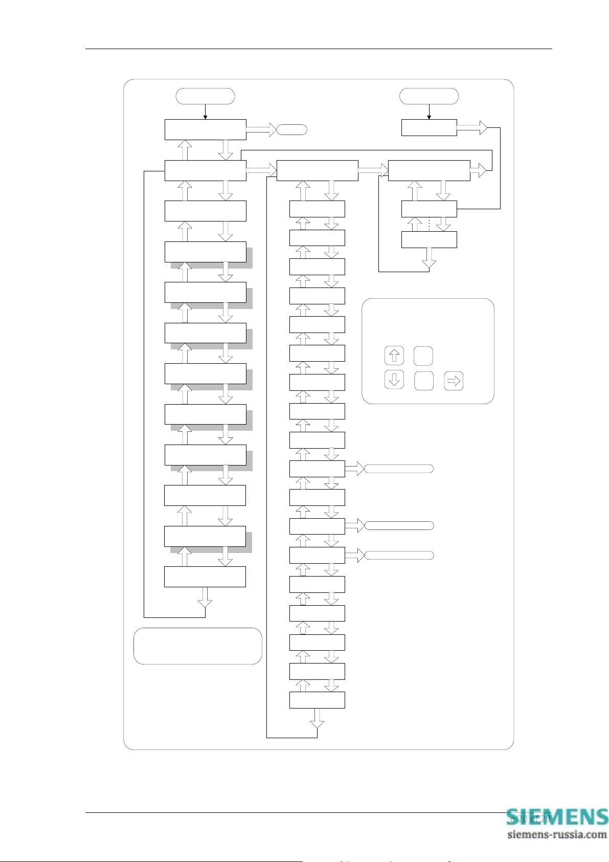
Figure 5 shows the display menu structure from where the available instruments can be accessed. Note that
pressing the Test/Reset key can clear three of the instruments, the Trip Counter, Waveforms and Events.
4.2 Data Storage
Details of relay operation are recorded in three forms, namely Waveform records, Event records and Faul t Data
records. All records are time and date stamped with a year 2000 compatible real time clock which maintains the
time even when the relay is de-energised [see Note below]. Time and date can be set either via the relay fascia
using appropriate commands in the System Config menu or via the communications inter face. In the latter case,
relays connected in a network can be synchronised by a global time sync command.
Alternatively, synchronising pulses can be received via a status input. To use this feature one of the status inputs
has to be assigned to the ‘Clock Sync’ feature in the Status Config menu. Additionally the ‘Clock Sync Period’
setting in the System Config menu should be set to either ‘seconds’ or ‘minutes’. If ‘seconds’ are selected then the
energisation of the selected status input will result in the clock being synchronised to the nearest secon d with the
milliseconds set to zero. If ‘minutes’ are selected then the clock is synchronised to the nearest minute with both
seconds and milliseconds set to zero.
Note : the real-time clock, waveform records and event records are all maintained, in the event of loss of auxiliar y
d.c. supply voltage, by the backup storage capacitor. This capacitor has the ability to maintain the charges on the
real-time clock IC and the SRAM memory device for typically 2-3 weeks time duration. This time, however, is
influenced by factors such as temperature and the age of the capacitor and could be shorter.
4.2.1 Waveform Records.
The waveform record feature stores analogue and digital information for the voltage input s, status inputs and
output relays. The waveform record is 1.0 second long (0.833sec at 60Hz) with a sampling resolution of 16
samples per cycle. The recorder feature has the ability to store records for the previous five trip operations of the
relay. These are labelled 1-5 with 1 being the most recent record.
The waveform recorder can be triggered in the following ways ;
• Via the waveform trigger status input signal.
• From any element Tr ip operation, including, Voltage, Frequency, NVD and NPS elements.
• Via the IEC870-5-103 communications interface.
The waveform recorder has a settable pre-fault triggering capability.
4.2.2 Event Records
The event recorder feature allows the time tagging of any change of state (event) of the relay. As an event occurs,
the actual event condition is logged as a record along with a time and date stamp to a resolution of 5ms. There is
capacity for a maximum of 500 event records to be stored in the relay and when the event buffer is full, any new
record will over-write the oldest. The following events are logged :
©2011 Siemens Protection Devices Limited Chapter 1 Page 11 of 20
Page 14

7SG11 Argus 8 Description of Operation
• Change of setting (though not the actual setting change). Also indication of which group of settings is
active.
• Change of state of each output relay.
• Change of state of each status Input.
• Change of state of any of the protection functions of the relay.
• Trip indication reset
• Trip test.
• Trip supply failure.
For a full list of all the events available see Table 6.
4.2.3 Fault Data Records
When issuing a trip output under fault conditions, the Argus 8 relay will illuminate the T r ip LED, store a fault
record and display the fault indication screen. The fault indication screen displays a summary of the fault data
record, giving immediate, easily understood information on what has occurred. It displays date (DD/MM), time
(HH:MM:SS) and the poles which were picked up when the trip signal was issued e.g.
25/04 17:25:51
TRIP A B C
This display is held until the TEST/RESET button is pressed, upon which the LED will turn off and any latched
output relays are reset. The relay enters ‘Fault Data Display Mode’ at which point the fault indication screen is
replaced by a more detailed scrolling fault data display. This shows date and time of fault and for each pole the
elements which were picked up and the voltages measured at the time of trip e.g.
FAULT 1 25/04/00 17:25:51.5400 G1, VAB VE1 VE2 VE3 VE4 110.22V, Vo <3VoE1> <3VoE2> 110.2 15V,FE1
FE2 FE3 FE4 50.499Hz
FAULT 1
<< Fault Data >>
The fault record is viewed in the ‘Fault Data Display Mode’ of the menu system and can be viewed again at a later
date. The relay will store the last 10 fault records, which are numbered 1-10, with 1 being the most recent record.
To view them, scroll downwards using the button.
Depending upon the relay application, some of the protection elements may not be used for tripping purposes but
for alarm purposes. In these cases it would be undesirable for the Argus to light the Trip LED and give fault
indication. It is therefore necessary to define a ‘Fault’ for the cases where a trip is issued. A ‘Fault Trigger’ setting
exists in the Data Storage Menu, which allows a fault condition to be defined by selecting any combination of
output relays as tripping outputs. The Trip LED and the fault record storage will be triggered when any of the
selected output relays are energised. Note that a trip output can still be generated even if the fault trigger setting
is not used, though no trip indication will be given.
Fault records are stored in non-volatile memory.
4.3 Communications
A fibre optic communication port is provided which gives superior EMC performance. Communication is
compatible with the IEC870-5-103 FT 1.2 transmission and application standards. For communication with the
relay via a PC (personal computer) a user-friendly software package, REYDISP EVOLUTION [1], is available to
allow transfer of the following:
• Relay Settings
• Waveform Records
• Event Records
• Fault Data Records
• Instrument and meters
• Control Functions
Communications operation is described in detail in Section 4 of this manual.
©2011 Siemens Protection Devices Limited Chapter 1 Page 12 of 20
Page 15
7SG11 Argus 8 Description of Operation
4.4 General Alarm Screens
The Argus 8 relay has an independent display function that provides up to nin e General Alarm screens, each of
which may be programmed by the user to display a message associated with an external alarm.
Within the System Config Menu, each alarm message can be text edited by the user to display up to 13
characters. Also, each alarm can be user mapped to any status input, via the Status Config Menu, so that on
energisation of that input the associated alarm message is automatically displayed. Where more than one
General Alarm is raised then the display will scroll right to left to show all energised screens sequentially, with
screens separated by a ‘+’ sign. If required, more than one alarm may be mapped to a single status input,
allowing long messages to be displayed.
The message will appear on the LCD for the duration of the time that the status input is energised.
General Alarms
<< Alarm1 + Al<<
4.5 Default Instrument Screens
The menu presentation of the various instruments allows the user to view a single screen at a time. Ho wever, for
in-service use, it is desirable that a small number of high interest, user selectable, screens are presented
automatically by default without user intervention. The instrument screens of interest to the user e.g. those
required to be presented to a visiting engineer for record purposes can be selected by the user by pressing
ENTER when viewing the required screen. On pressing ENTER a ‘Screen Set As Default’ message will be
flashed up and a ‘D’ will appear at the top right of that screen. The ‘D’ indicates that a screen is a ‘default screen’.
To de-select a default screen, simply press ENTER while on that particular screen and a ‘Screen Cleared As
Default’ message will be flashed up. The ‘D’ symbol will be cleared.
Frequency
50.003Hz
If no keys have been pressed for a pre-determined time the relay will jump to the default instrument display
regardless of where the menu system has been left by the user. It will then scroll through each of the selected
default instruments and remain on each for 5 seconds. The main timer, which sets the time to elapse before the
relay goes into the default instruments mode is found in the System Config Menu. This is the Default Screen
Timer setting and it can be set to a range of values from 10 seconds to 1 hour. See relay settings, Section 3 of
this manual.
If any General Alarm is raised, then the general alarm screen will be presented in the default screen seq uence.
The general alarm screen, which has a scrolling display, will present one pass of its display message.
Any key press while in the default screen sequence will result in a return to the ‘Relay Ide ntifier’ screen at the top
of the menu structure.
4.6 Multiple Settings Groups.
Argus relays provide eight alternative setting groups, making it possible to edit one group while the rela y
protection algorithms operate using another ‘active’ group. An indication o f which group is being viewed is given
by the ‘Gn’ character in the top left of the display. The relay can then be switched from one group of settings to
another to suit alterations in the power system configuration. Changeover will occur within 25ms.
A change of group can be achieved either locally at the relay fascia, remotely via a communication interface
command or by energisation of a status input. In the case of the latter method, the ‘Settings Group Select’ setting
is used to configure any one (or more) of the status inputs to select a settings group. The selected group is then
made active if the status input is energised and remains active for as long as the input remains energised.
4.7 Password Feature
The programmable password feature enables the user to enter a 4 char acter alphanumeric code to secure access
to the relay settings. The relay is supplied with the password set to ‘NONE’ which means that the password
feature is not activated. Once a password has been entered then it will be required thereafter to change settings.
It can, however, be de-activated by using the password to gain access and by resetting it back to ‘NONE’.
As soon as the user attempts to change a setting the password is requested before any setting alterations are
allowed. Once the password has been validated, the user is ‘logged on’ and any further changes can be made
without re-entering the password. If no more changes are made within 1 hour then the user will automatically be
‘logged off’, re-enabling the password feature.
©2011 Siemens Protection Devices Limited Chapter 1 Page 13 of 20
Page 16

7SG11 Argus 8 Description of Operation
Note that the password validation screen also displays a numerical code. If the password is lost or forgotten, this
code can be communicated to Reyrolle Protection by authorised personnel, and the p assword can be retrieved.
4.8 Trip Circuit Supervision
A trip circuit supervision feature is provided within the relay. The Argus 8 can monitor its own trip circuit by
configuring one of its status inputs using the ‘Trip Circuit Fail’ setting and connecting the status input into the trip
circuit. Indication is then given instantaneously of ‘Trip Circuit Fail’ should a fault be detected and this display also
identifies which input has detected the fault. Since the status inputs can be programmed to operate output
contacts, an alarm can be also generated from the trip circuit supervision feature.
See Section 5 - Applications Guide, subsection 2.6 for more details on the trip circuit supervision scheme.
5 User Interface
The user interface is designed to provide a user-friendly method of entering settings and retrieving data from the
relay. The relay fascia includes a 16 character by 2 line, backlit, liquid crystal displa y (LCD), 3 light emitting
diodes (LED) and 5 push buttons.
5.1 Liquid Crystal Display
The liquid crystal display is used to present settings, instrumentation and fault data in a textual format. To
conserve power the display backlighting is turned off if no push buttons are pressed for 5 minutes. After one hour
the whole display is de-activated except if the display is left in the ‘Instruments Mode’ where it remain visible
permanently so that instruments can be displayed continuously. Also, if any default instruments have been
selected then the display will not power down, only the backlight will turn off. Once the backlight is turned off, any
following key press will turn the backlight on without changing the display.
5.2 LED Indications
The following indications are provided :
• Prot ectio n Healthy – Green LED (flashes with fault).
This LED is solidly illuminated to indicate that DC volts have been applied to the relay and that the relay is
operating correctly. If the internal relay watchdog detects a permanent fault then this LED will continuously flash.
• Starter – Yello w LED (self resetting).
This LED indicates that any of the protection element starters are operating.
• Trip – Red L ED (latched).
This LED indicates that a trip as defined by the user has occurred. Such a trip may be issued by any of the relay’s
protection functions.
5.3 Keypad
Five pushbuttons are used to control the functions of the relay. They are labeled ENTER and CANCEL.
Note that the button is also labeled TEST/RESET.
When the relay front cover is in place only the and buttons are accessible. This allows only read access to all
the menu displays. It is not possible to change settings.
5.4 Navigating the Menu System
The display menu structure is shown in Figure 5. This diagram shows the three main modes of display, which are
the Settings Mode, Instruments Mode and the Fault Data Mode.
On relay start up the user is presented with a default relay identifier,
ARGUS 8
Factory Settings
©2011 Siemens Protection Devices Limited Chapter 1 Page 14 of 20
Page 17

7SG11 Argus 8 Description of Operation
which shows that the relay has been set with the standard factory default settings. The top line of the LCD can be
changed to some user-definable identifier or code if preferred.
Pressing the key on this display initiates an LED test. Pressing at this display allows access to the three
display modes which are accessed in turn by pressing the key.
The ‘Settings Mode’ contains up to 10 setting sub-menu’s. (Note :- this number can vary depending up on relay
configuration). These hold all of the programmable settings of the relay in separate logical groups. The sub
menu’s are accessed by pressing the key. This enters the sub menu and presents a list of all the settings within
that sub menu. Pressing the key scrolls through the settings until after the last setting in the group the next sub
menu is presented. Access to this group is via the same method as before. If a particular sub menu is not
required to be viewed then pressing the key will skip past that particular menu and present the next one in the
list. Note that all screens can be viewed even if the password is not known. The password only pr otects against
unauthorised changes to settings.
While viewing an editable screen pressing the ENTER key allows the user to change the displayed data. The
editable field will be indicated by a flashing character(s). Pressing or scrolls through the available setting
values or, pressing the key moves right through the edit fields. Note that all settings can be incremented or
decremented using the or keys and they all wrap-around so that to go from e.g. a setting minimum value to
the maximum value it is quicker to press the key, rather than scroll up through every setting. Also, to facilitate
quicker setting changes an acceleration feature is available which if or are depresse d and held, then the rate
of scrolling through the setting values increases.
If CANCEL is pressed during a setting change operation the original setting valu e is restored and the display is
returned to the normal view mode.
If changes are made to the setting value then pressing ENTER disables the flashing character mode and displays
the new setting value. This is immediately stored in non-volatile memory.
Note : the relay exhibits a method of hiding settings which are not relevant to a particular customer scheme which
is known as setting dependencies. Some settings are dependant on others being enabled and if a function is not
enabled then associated settings are not displayed e.g. if Voltage Element 1 is not required then set,
Gn V Element 1 Operation to OFF ; the following associated settings will not be displayed ;
Gn V Element 1 Setting
Gn V Element 1 Delay
Gn V Element 1 Hysteresis
Gn V Element 1 O/P Phases
Also hidden are all associated output relays options and status input inhib its.
There are many examples of setting dependencies and care must be taken to ensure a function is en abled before
looking for other associated settings which otherwise would be hidden.
The ‘Instruments Mode’ contains a maximum of 17 instruments. This number is dependent upon the relay
configuration and therefore some instruments may not be displayed. Pressing the key scrolls down through the
list of instruments and pressing scrolls up through them. For more information on the relay’s instruments see
Sections 4.1 and 4.5.
The ‘Fault Data Mode’ can contain a maximum of 10 fault records. These are accessed in the same way as the
other display modes. For more information on the fault record displays see Section 4.2.3.
For a complete list of all possible settings see Section 3 – of this manual. This section also shows all setting
ranges and factory default values, as well as including a brief description of each setting function.
©2011 Siemens Protection Devices Limited Chapter 1 Page 15 of 20
Page 18
7SG11 Argus 8 Description of Operation
Function Terminal Terminal Function
Va / (Vab) Start
Vo / (Vbc) Start
Status Input 1 (+)
Relay 1 (N/C) –
Relay 2 (N/O) –
Relay 4 (N/O) –
Aux. Volts (+)
Earth
Relay 3 (COM) –
Terminal Block 1
Relay 5 (N/O) –
Relay 6 (N/O) –
Relay 7 (N/O) –
Status Input 4 (+)
Status Input 2 (+)
Table 4 - Connection Table (E4 Versions)
1 2
3 4
5 6
7 8
9 10
11 12
13 14
15 16
17 18
19 20
21 22
23 24
25 26
27 28
Finish Va / (Vab)
Finish Vo / (Vbc)
(–) Status Input 1
(–) Aux. Volts
(+) Status Input 3
(–) Status Common
– Relay 1 (N/C)
– Relay 2 (N/O)
– Relay 4 (N/O)
– Relay 3 (N/O)
– Relay 3 (N/C)
– Relay 5 (N/O)
– Relay 6 (N/O)
– Relay 7 (N/O)
©2011 Siemens Protection Devices Limited Chapter 1 Page 16 of 20
Page 19
Function Terminal Terminal Function
Not Used –
Status Input 1 (+)
Relay 1 (N/C) –
Relay 1 (N/O) –
Relay 2 (COM) –
Relay 4 (N/O) –
Aux. Volts (+)
Earth
Relay 3 (COM) –
Terminal Block 1
Relay 5 (N/O) –
Relay 6 (N/O) –
Relay 7 (N/O) –
Not Used –
Not Used –
Status Input 5 (+)
Status Input 4 (+)
Status Input 3 (+)
Status Input 2 (+)
Relay 8 (N/O) –
Relay 9 (N/O) –
Relay 10 (N/O) –
Relay 11 (N/O) –
Not Used –
Terminal Block 2
Not Used –
Not Used –
Vc / (Vca) / (Vo) Start
Vb / (Vbc) Start
Va / (Vab) Start
Alternative expansion board :
7SG11 Argus 8 Description of Operation
1 2
3 4
5 6
7 8
9 10
11 12
13 14
15 16
17 18
19 20
21 22
23 24
25 26
27 28
29 30
31 32
33 34
35 36
37 38
39 40
41 42
43 44
45 46
47 48
49 50
51 52
53 54
55 56
(–) Status Input 1
(–) Aux. Volts
(–) Status Input 5
(–) Status Input 4
(–) Status Input 3
(–) Status Input 2
Finish Vc / (Vca) / (Vo)
Finish Vb / (Vbc)
Finish Va / (Vab)
– Not Used
– Relay 1 (COM)
– Relay 2 (N/O)
– Relay 2 (N/C)
– Relay 4 (N/O)
– Relay 3 (N/O)
– Relay 3 (N/C)
– Relay 5 (N/O)
– Relay 6 (N/O)
– Relay 7 (N/O)
– Not Used
– Not Used
– Relay 8 (N/O)
– Relay 9 (N/O)
– Relay 10 (N/O)
– Relay 11 (N/O)
– Not Used
– Not Used
– Not Used
Status Input 9 (+)
Status Input 8 (+)
Status Input 7 (+)
Status Input 6 (+)
Table 5 - Connection Table (E6 Versions)
37 38
39 40
41 42
43 44
(–) Status Input 9
(–) Status Input 8
(–) Status Input 7
(–) Status Input 6
©2011 Siemens Protection Devices Limited Chapter 1 Page 17 of 20
Page 20

7SG11 Argus 8 Description of Operation
The following event codes can be stored in the relay and will be time stamped to a resolution of 5ms. There can
be a maximum of 500 events stored in the event buffer as per the Argus range of relays. The Argus 8 events are
assigned to function code 167.
Event Description Frame
Type
Data Lost 1 RaisedOnly
Reset FCB 5 RaisedOnly
Reset CU 5 RaisedOnly
Start/Restart 5 RaisedOnly 4
Power On 5 RaisedOnly
External Trip 1 RaisedOnly
LED’s Reset 1 RaisedOnly
Trip Test 1 RaisedAndCleared
Settings Changed 1 RaisedAndCleared
Setting Group 1 Selected 1 RaisedAndCleared
Setting Group 2 Selected 1 RaisedAndCleared
Setting Group 3 Selected 1 RaisedAndCleared
Setting Group 4 Selected 1 RaisedAndCleared
Setting Group 5 Selected 1 RaisedAndCleared
Setting Group 6 Selected 1 RaisedAndCleared
Setting Group 7 Selected 1 RaisedAndCleared
Setting Group 8 Selected 1 RaisedAndCleared
Input 1 1 RaisedAndCleared
Input 2 1 RaisedAndCleared
Input 3 1 RaisedAndCleared
Input 4 1 RaisedAndCleared
Input 5 1 RaisedAndCleared
Input 6 1 RaisedAndCleared
Input 7 1 RaisedAndCleared
Input 8 1 RaisedAndCleared
Input 9 1 RaisedAndCleared
Event Operation GI Code
18
19
21
22
23
24
25
26
35
36
37
38
27
28
29
30
45
46
47
48
49
0
2
3
5
Output 1 1 RaisedAndCleared
Output 2 1 RaisedAndCleared
Output 3 1 RaisedAndCleared
Output 4 1 RaisedAndCleared
Output 5 1 RaisedAndCleared
Output 6 1 RaisedAndCleared
Output 7 1 RaisedAndCleared
Output 8 1 RaisedAndCleared
Output 9 1 RaisedAndCleared
Output 10 1 RaisedAndCleared
Output 11 1 RaisedAndCleared
Voltage Block 1 RaisedAndCleared
Waveform Stored 1 RaisedOnly
Remote CTRL Interrupted 1 RaisedOnly
Power On Counter Alarm 1 RaisedAndCleared
Trip Circuit Fail 1 RaisedAndCleared
Trip Count Alarm 1 RaisedAndCleared
General Alarm 1 1 RaisedAndCleared
General Alarm 2 1 RaisedAndCleared
General Alarm 3 1 RaisedAndCleared
51
52
53
54
55
56
57
58
59
60
61
79
80
81
92
20
33
121
122
123
©2011 Siemens Protection Devices Limited Chapter 1 Page 18 of 20
Page 21

7SG11 Argus 8 Description of Operation
Event Description Frame
Type
General Alarm 4 1 RaisedAndCleared
General Alarm 5 1 RaisedAndCleared
General Alarm 6 1 RaisedAndCleared
General Alarm 7 1 RaisedAndCleared
General Alarm 8 1 RaisedAndCleared
General Alarm 9 1 RaisedAndCleared
V Element 1 Starter 1 RaisedAndCleared
V Element 2 Starter 1 RaisedAndCleared
V Element 3 Starter 1 RaisedAndCleared
V Element 4 Starter 1 RaisedAndCleared
F Element 1 Starter 1 RaisedAndCleared
F Element 2 Starter 1 RaisedAndCleared
F Element 3 Starter 1 RaisedAndCleared
F Element 4 Starter 1 RaisedAndCleared
3Vo Element 1 Starter 1 RaisedAndCleared
3Vo Element 2 Starter 1 RaisedAndCleared
V2 Element 1 Starter 1 RaisedAndCleared
V2 Element 2 Starter 1 RaisedAndCleared
V Element 1 Trip 1 RaisedOnly
V Element 2 Trip 1 RaisedOnly
V Element 3 Trip 1 RaisedOnly
V Element 4 Trip 1 RaisedOnly
F Element 1 Trip 1 RaisedOnly
F Element 2 Trip 1 RaisedOnly
F Element 3 Trip 1 RaisedOnly
F Element 4 Trip 1 RaisedOnly
3Vo Element 1 Trip 1 Raise dOnly
3Vo Element 2 Trip 1 Raise dOnly
V2 Element 1 Trip 1 RaisedOnly
V2 Element 2 Trip 1 RaisedOnly
Event Operation GI Code
124
125
126
127
128
129
170
171
172
173
174
175
176
177
178
179
180
181
182
183
184
185
186
187
188
189
190
191
192
193
Table 6 - Event Codes
©2011 Siemens Protection Devices Limited Chapter 1 Page 19 of 20
Page 22
7SG11 Argus 8 Description of Operation
CANCEL FAULT
RELAY IDENTIFIER
SETTINGS
MODE
SYSTEM CONFIG
MENU. TO VIEW
VOLTAGE
MENU. TO VIEW
NEUTRAL VOLTAGE
MENU. TO VIEW
NPS OVERVOLTAGE
MENU. TO VIEW
FREQUENCY
MENU. TO VIEW
O/P RELAY CONFIG
MENU. TO VIEW
READ UP
READ DOWN
FAULT DATA
DISPLAY
FAULT DATA
MODE
FAULT 1
FAULT 10
ENTER
CANCEL
TEST/RESET
LED TEST
INSTRUMENTS
MODE
VA = 63.55 KV
VB = 63.47 KV
G1
G8
G1
G8
G1
G8
G1
G8
G1
G8
VC = 63.52 KV
Va = 63.42 V
Vb = 63.34 V
Vc = 63.49 V
Vo = 0.020 V
V1 = 63.55 V
V2 = 0.03 V
Frequency
50.003 Hz
Relay Status
1_1111____1
Status Inputs
1_1_1
NOTE : THE ARROWS IN THE DIAGRAM
REPRESENT THE KEY PRESSES REQUIRED
TO NAVIGATE THE MENU SYSTEM.
G1
STATUS CONFIG
G8
MENU. TO VIEW
COMMS INTERFACE
MENU. TO VIEW
G1
DATA STORAGE
G8
MENU. TO VIEW
CB MAINTENANCE
MENU. TO VIEW
NOTE : THE SETTING SUBMENUS ABOVE
ARE NOT ALWAYS VISIBLE. THEY ARE
DEPENDENT UPON RELAY TYPE AND
VARIOUS CONFIGURATION OPTIONS.
General Alarms
No Alarms Raised
Trip Counter
128
Power On Count
7
Waveforms
Events Stored
Date = 02/05/99
Time = 11:14:34
V Starters
VE1 VE4
V2 Starters
V2E1
Vo Starters
3VoE2
F Starters
FE1 FE2
237
RESET TRIP COUNTER
5
RESET WAVEFORMS STORED
RESET EVENTS STORED
Figure 5 - Display Menu Structure
©2011 Siemens Protection Devices Limited Chapter 1 Page 20 of 20
Page 23
7SG11 Argus 8 Performance Specification
7SG11 Argus 8
Voltage and Frequency Relays
Document Release History
This document is issue 2010/02 The list of revisions up to and including this issue is:
Pre release
2010/02 Document reformat due to rebrand
Software Revision History
2011/11 2422H80004R7 Fault trigger when the voltage blocking threshold is OFF.
IEC 60870-5-103 fault numbering for fault and its measurands
The copyright and other intellectual property rights in this document, and in any model or article produced from it
(and including any registered or unregistered design rights) are the property of Siemens Protection Devices
Limited. No part of this document shall be reproduced or modified or stored in another form, in any data retrieval
system, without the permission of Siemens Protection Devices Limited, nor shall any model or article be
reproduced from this document unless Siemens Protection Devices Limited consent.
While the information and guidance given in this document is believed to be correct, no liability shall be accepted
for any loss or damage caused by any error or omission, whether such error or omission is the result of
negligence or any other cause. Any and all such liability is disclaimed.
©2011 Siemens Protection Devices Limited
Page 24

7SG11 Argus 8 Performance Specification
Contents
1 General .............................................................................................................................................................. 3
2 Characteristic Energizing Quantity ..................................................................................................................... 3
3 Auxiliary Energising Quantity ............................................................................................................................. 3
3.1 DC Power Supply...................................................................................................................................... 3
3.2 DC Status Inputs....................................................................................................................................... 3
4 Setting Ranges................................................................................................................................................... 4
5 Accuracy Reference Conditions ......................................................................................................................... 4
6 Accuracy ............................................................................................................................................................ 4
6.1 Overvoltage Element ................................................................................................................................ 4
6.2 Undervoltage Element .............................................................................................................................. 5
6.3 Neutral Voltage Element........................................................................................................................... 5
6.4 NPS Overvoltage Element........................................................................................................................ 5
6.5 Overfrequency Element ............................................................................................................................ 5
6.6 Underfrequency Element .......................................................................................................................... 6
6.7 DTL Timing Elements ............................................................................................................................... 6
7 Accuracy General............................................................................................................................................... 6
8 Accuracy Influencing Factors ............................................................................................................................. 6
9 Thermal Withstand ............................................................................................................................................. 6
10 Burdens.............................................................................................................................................................. 6
11 Output Contacts ................................................................................................................................................. 7
12 Environmental Withstand ................................................................................................................................... 7
12.1 General...................................................................................................................................................... 7
12.2 Immunity .................................................................................................................................................... 7
12.3 Emissions .................................................................................................................................................. 8
12.4 Mechanical ................................................................................................................................................. 8
Table of Figures
Figure 1 - Typical O/V Operate Time Characteristic ............................................................................................9
Figure 2 - Typical U/V Operate Time Characteristic ............................................................................................9
©2011 Siemens Protection Devices Limited Chapter 2 Page 2 of 9
Page 25
7SG11 Argus 8 Performance Specification
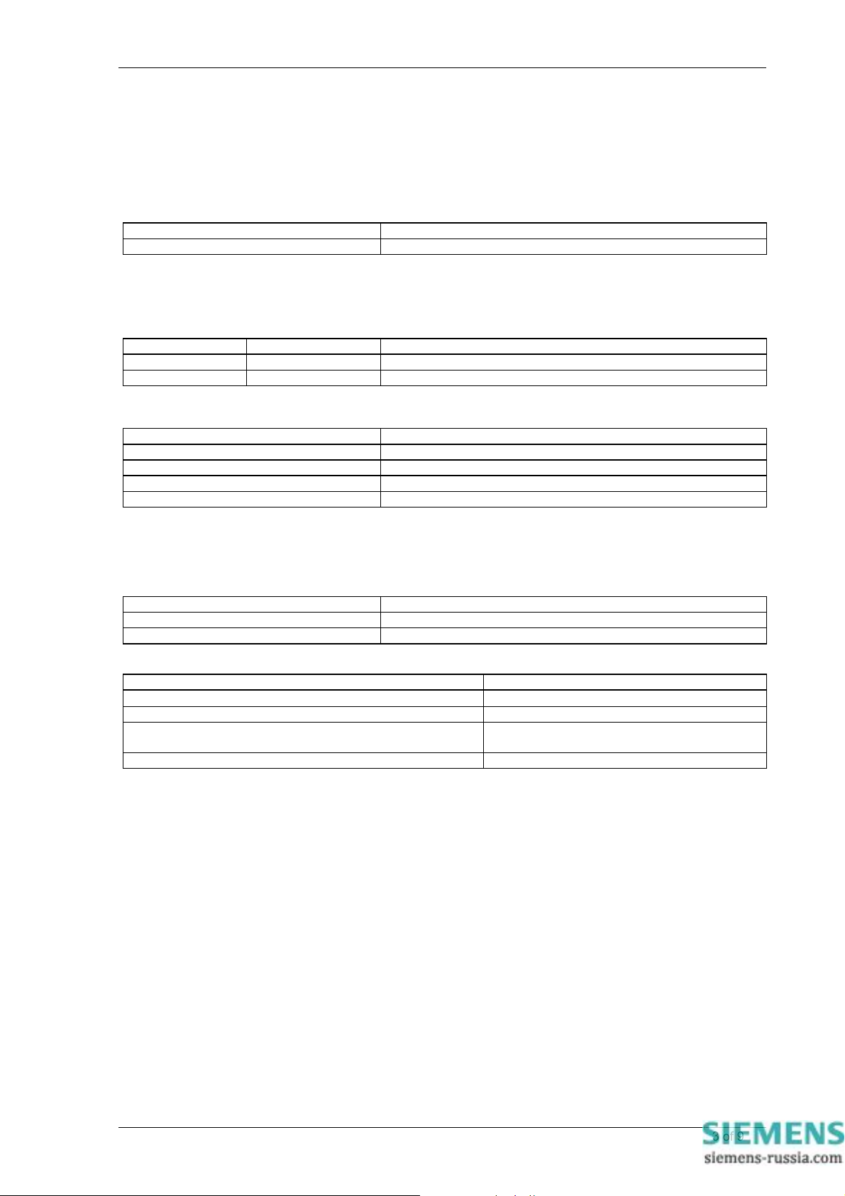
1 General
The relay complies with the relevant clauses in the following specification :-
• IEC 60255 - 3
2 Characteristic Energizing Quantity
AC Voltage Vn 63.5 / 110 Vrms
Frequency 50 / 60Hz
3 Auxiliary Energising Quantity
3.1 DC Power Supply
Nominal Operating Range
V
24, 30, 48V 18V to 60V dc
AUX
V
110, 220V 88V to 280V dc
AUX
3.2 DC Status Inputs
Nominal Voltage Operating Range
30 18V to 37.5V
48 37.5V to 60V
110 87.5V to 137.5V
220 175 to 280V
NB : the status operating voltage need not be the same as the main energising voltage. For 110/125V or
220/250V working, a standard Argus relay with 48/54V status can be supplied for use with external dropper
resistors as follows:-
Status Input External Resistances
Nominal Voltage Resistor Value (Wattage)
110 2k7 ± 5% ; (2.5W)
220 8k2 ± 5% ; (6.0W)
Status Input Performance
Minimum DC current for operation 10mA
Reset/Operate Voltage Ratio
Typical response time < 5ms
Typical response time when programmed to energise an
output relay contact
Minimum pulse duration 40ms
Each status input has associated timers which can be programmed to give time delayed pick-up and time delayed
drop-off. The drop-off timers have default settings of 20ms, thus providing immunity to an AC input signal. Status
inputs will not respond to the following:
• 250V RMS 50/60Hz applied for two seconds through a 0.1μF capacitor.
• 500V RMS 50/60Hz applied between each terminal and earth.
• Discharge of a 10μF capacitor charged to maximum DC auxiliary supply voltage.
The inputs meet the requirements of ESI 48-4.
Note : special versions of status input are available for direct operation from 110V and 220V supplies. These do
not comply with the ESI 48-4 specification and will operate with a DC current of less than 10mA.
≥ 90%
< 15ms
©2011 Siemens Protection Devices Limited Chapter 2 Page 3 of 9
Page 26
7SG11 Argus 8 Performance Specification
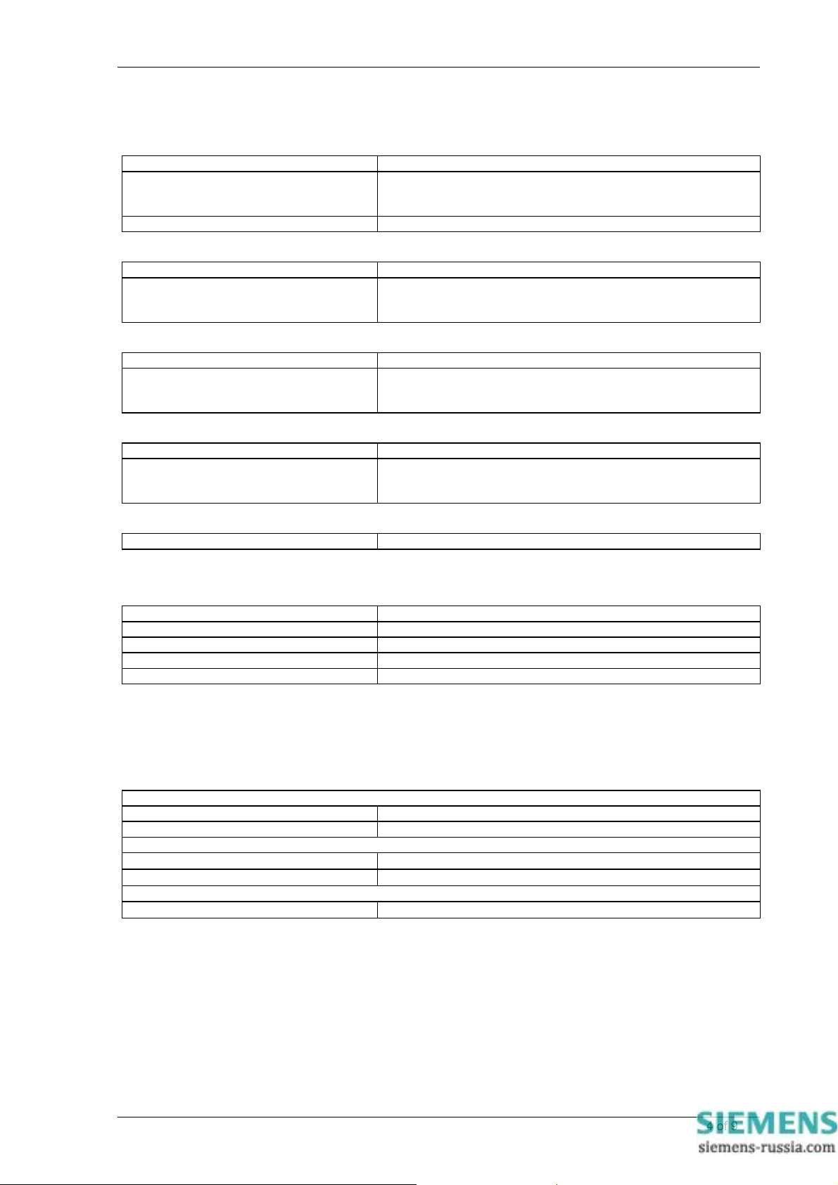
4 Setting Ranges
Voltage Element Settings
V Element Setting 5V – 200V step 0.5V
V Element Delay 0.00-20.00 step 0.01sec
20.0-100.0 step 0.5sec
100-600 step 1.0sec
V Element Hysteresis 1% – 90% step 1%
Neutral Voltage Settings
3Vo Element Setting 1V – 100V step 0.5V
3Vo Element Delay 0.00-20.00 step 0.01sec
20.0-100.0 step 0.5sec
100-600 step 1.0sec
NPS Overvoltage Settings
V2 Element Setting 1V – 100V step 0.5V
V2 Element Delay 0.00-20.00 step 0.01sec
20.0-100.0 step 0.5sec
100-600 step 1.0sec
Frequency Element Settings
F Element Setting 47.00Hz - 62.00Hz step 0.01Hz
F Element Delay 0.00-20.00 step 0.01sec
20.0-100.0 step 0.5sec
100-600 step 1.0sec
Voltage Blocking Element
Voltage Blocking Threshold OFF, 1V – 100V step 1.0V
5 Accuracy Reference Conditions
General IEC 60255 –3
Auxiliary Supply Nominal
Rating 63.5 or 110 Vrms
Frequency 50 or 60Hz
Ambient Temperature 20°C
6 Accuracy
The following accuracy is specified at reference conditions.
6.1 Overvoltage Element
Overvoltage Element
Operate Level Setting ± 1% or 0.25V
Reset Level ≥ (operate level – hysteresis setting)
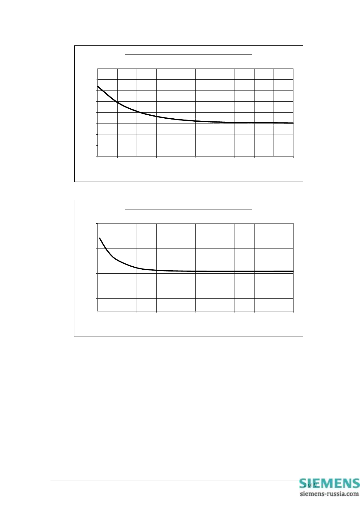
Operate Time (see Fig.1) – to output contact
0V to 2x setting
0V to 1.1x setting
Reset Time
1.1x to 0.9x setting
≤ 45ms
≤ 55ms
≤ 50ms
©2011 Siemens Protection Devices Limited Chapter 2 Page 4 of 9
Page 27
7SG11 Argus 8 Performance Specification
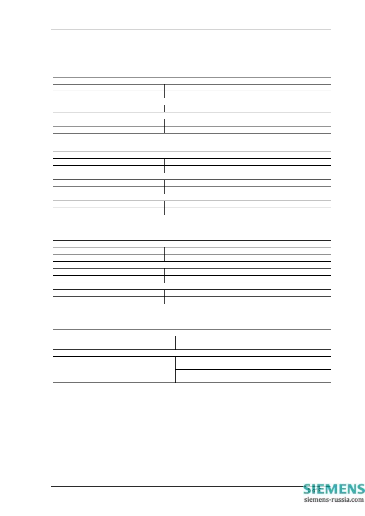
6.2 Undervoltage Element
Undervoltage Element
Operate Level Setting ± 1% or 0.25V
Reset Level
Operate Time (see Fig.2)
1.1x to 0.9x setting
Reset Time
0V to 1.1x setting
0V to 2x setting
≤ (operate level + hysteresis setting)
≤ 65ms
≤ 75ms
≤ 65ms
6.3 Neutral Voltage Element
Neutral Voltage Element
Operate Level Setting ± 1% or 0.25V
Reset Level
Operate Time
0V to 2x setting
0V to 1.1x setting
Reset Time
1.1x to 0.9x setting
1.1x to 0V
1
– For NVD settings below 7.5V the Reset Level can be up to 60% of operate value.
> 95% of operate value
≤ 85ms
≤ 85ms
≤ 80ms
≤ 70ms
1
6.4 NPS Overvoltage Element
Negative Phase Sequence Element
Operate Level Setting ± 1% or 0.25V
Reset Level > 95% of operate value2
Operate Time
0V to 2x setting
0V to 1.1x setting
Reset Time
1.1x to 0.9x setting
1.1x to 0V
2
– For NPS settings below 3.5V the Reset Level can be up to 80% of operate value.
≤ 85ms
≤ 85ms
≤ 80ms
≤ 70ms
6.5 Overfrequency Element
Overfrequency Element
Operate Level Setting ± 10mHz
Reset Level Operate – 20mHz
Operate Time
For ROCOF between 0.1-10 Hz/sec
Typically < 140ms
Maximum < 175ms
Typically < 100ms : AG8 - 300 series only
Maximum < 150ms
©2011 Siemens Protection Devices Limited Chapter 2 Page 5 of 9
Page 28
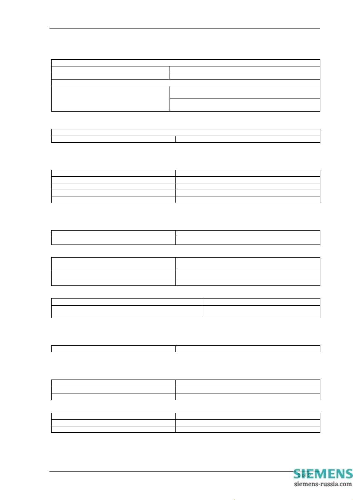
6.6 Underfrequency Element
Underfrequency Element
Operate Level Setting ± 10mHz
Reset Level Operate + 20mHz
Operate Time
For ROCOF between 0.1-10 Hz/sec
Typically < 140ms
Maximum < 175ms
Typically < 100ms : AG8 - 300 series only
Maximum < 150ms
6.7 DTL Timing Elements
All Timers
Timing Accuracy ±1% or 30ms
7 Accuracy General
Measuring Accuracy (50 or 60 Hz)
Phase Voltage ± 1% or 0.25V
Vo (Measured) ± 1% or 0.5V
Vo (Calculated) ± 1% or 0.5V
V2 (NPS) ± 1% or 0.5V
Frequency < ± 10mHz
7SG11 Argus 8 Performance Specification
8 Accuracy Influencing Factors
Temperature
Ambient Range -10°C to +55°C
Variation over range
Frequency
Range 47Hz to 52Hz
Setting variation
Operating time variation
Auxiliary DC Supply - IEC 60255-11
Allowable superimposed ac component
Allowable breaks/dips in supply (collapse to zero from
nominal voltage)
≤ 5%
57Hz to 62Hz
≤ 1%
≤ 1%
≤ 12% of DC voltage
≤ 20ms
9 Thermal Withstand
Continuous Overload
AC Voltage 250Vrms ( 353Vpk)
10 Burdens
AC Burd en
AC Burden
110Vrms Input
63.5Vrms Input
DC Burden
DC Burden
Quiescent (Typical) 3 Watts
Max 10 Watts
≤ 0.1VA
≤ 0.05VA
©2011 Siemens Protection Devices Limited Chapter 2 Page 6 of 9
Page 29
7SG11 Argus 8 Performance Specification
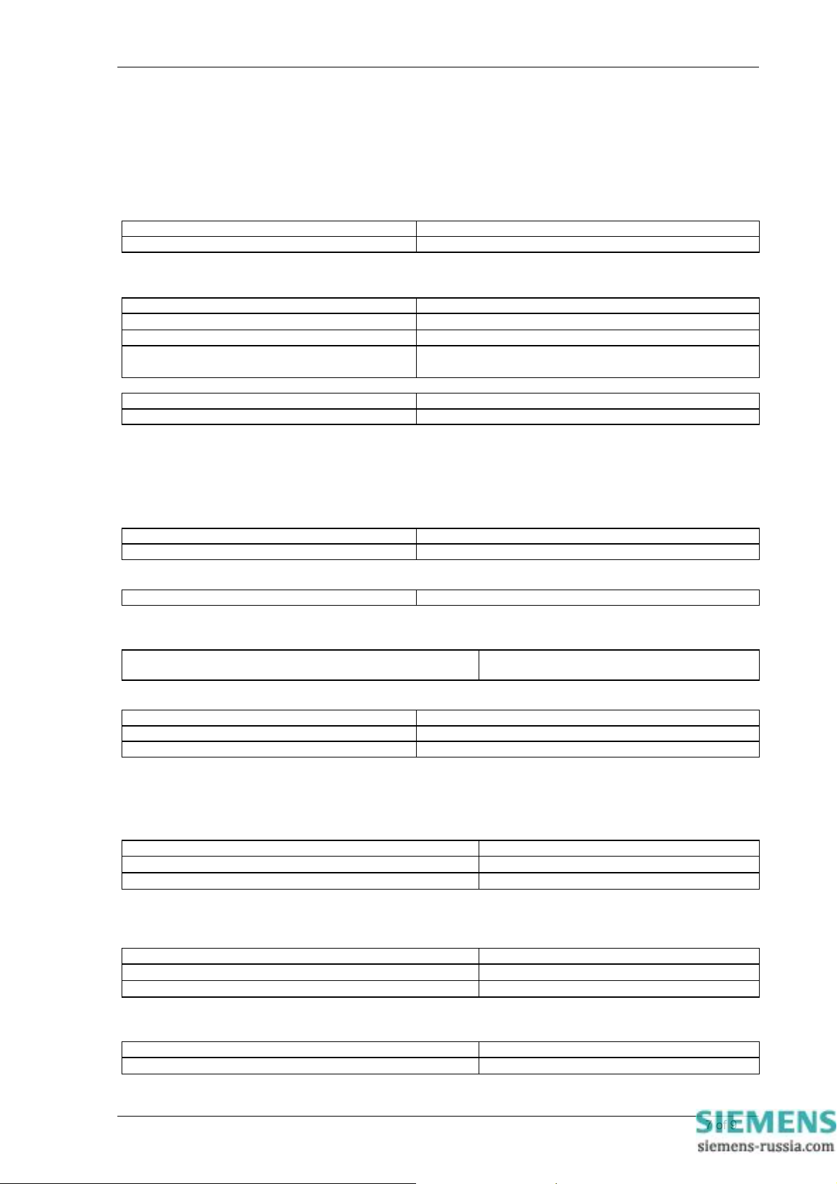
11 Output Contacts
Contact rating to IEC 60255-0-20.
Carry continuously 5A ac or dc
Make and Carry
(limit L/R ≤ 40ms and V ≤ 300 volts)
For 0.5 sec 20A ac or dc
For 0.2 sec 30A ac or dc
Break
(limit ≤ 5A or ≤ 300 volts)
Ac resistive 1250VA
Ac inductive
Dc resistive 75W
Dc inductive
Minimum number of operations 1000 at maximum load
Minimum recommended load 0.5W, limits 10mA or 5V
250VA @ PF ≤ 0.4
30W @ L/R ≤ 40 ms
50W @ L/R ≤ 10 ms
12 Environmental Withstand
12.1 General
Temperature - IEC 60068- 2-1/2
Operating range -10°C to +55°C
Storage range -25°C to +70°C
Humidity - IEC 60068- 2-3
Operational test 56 days at 40°C and 95% RH
Transient Overvoltage – IEC 60255-5
Between all terminals and earth or between any two
independent circuits without damage or flashover
Insulation - IEC 60255-5
Between all terminals and earth 2.0kV rms for 1 min
Between independent circuits 2.0kV rms for 1 min
Across normally open contacts 1.0kV rms for 1 min
5kV 1.2 / 50µs 0.5J
12.2 Immunity
High Frequency Disturbance IEC 60255-22-1 Class III
Variation
2.5kV Common (Longitudinal) Mode
1.0kV Series (Transverse) Mode
Electrostatic Discharge IEC 60255-22-2 Class 3
Variation
6kV contact discharge
8kV air discharge (to fascia)
Radio Frequency Interference IEC 60255-22-3 Class III
Variation
80MHz to 1000MHz, 10V/m
≤ 5%
≤ 5%
≤ 5%
≤ 5%
≤ 5%
©2011 Siemens Protection Devices Limited Chapter 2 Page 7 of 9
Page 30
7SG11 Argus 8 Performance Specification
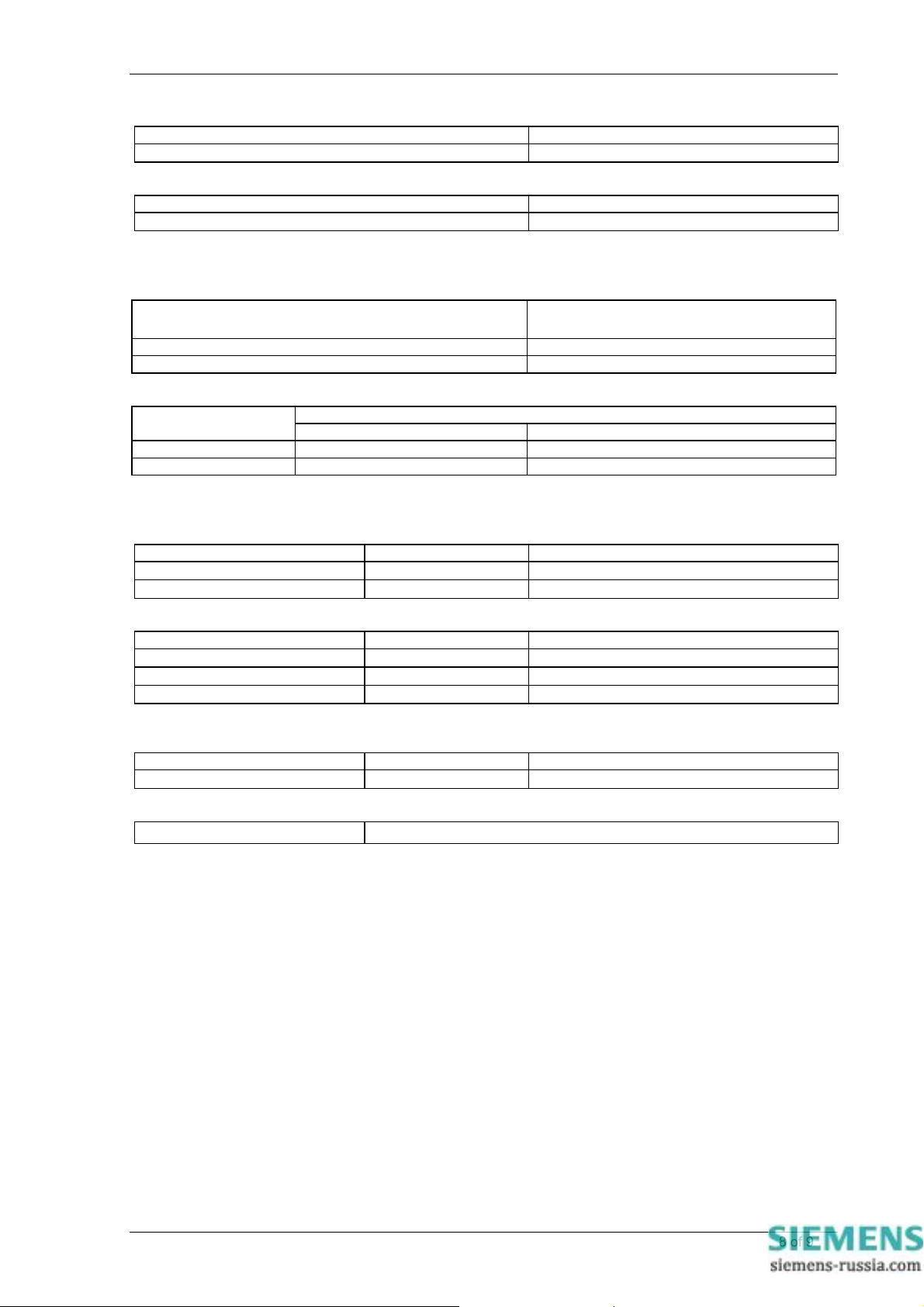
Fast Transient – IEC 60255-22-4 Class IV
Variation
4kV 5/50ns 2.5kHz repetitive
Conducted RFI – IEC 60255-22-6
Variation
0.15 to 1000MHz - 10V
≤ 5%
≤ 5%
12.3 Emissions
Radiated Limits – IEC 60255-25
Frequency Range Limits at 10m
Quasi-peak dB (µV/m)
30 to 230MHz 40
230 to 1000MHz 47
Conducted Limits – IEC 60255-25
Frequency Range
Quasi-peak Average
0.15 to 0.5MHz 79 66
0.5 to 30MHz 73 60
Limits dB (µV)
12.4 Mechanical
Vibration (Sinusoidal) – IEC 60255-21-1 Class 1
Variation
Vibration response 0.5gn
Vibration endurance 1.0gn
Shock and Bump – IEC 60255-21-2 Class 1
Variation
Shock response 5 gn 11ms
Shock withstand 15 gn 11ms
Bump test 10 gn 16ms
Seismic – IEC 60255-21-3 Class 1
Variation
Seismic Response 1gn
Mechanical Classification
Durability
Qualification
Product :- C compliant to all relevant EU directives.
Quality Systems :- accredited to ISO 9001
In excess of 106 operations
≤ 5%
≤ 5%
≤ 5%
≤ 5%
≤ 5%
≤ 5%
©2011 Siemens Protection Devices Limited Chapter 2 Page 8 of 9
Page 31
7SG11 Argus 8 Performance Specification
Typical Instantaneous O/V Operate Time Characteristic
65
60
55
50
45
40
35
Operate Time (msec)
30
25
100 110 120 130 140 150 160 170 180 190 200
Applied Overvoltage (% of setting)
Figure 1 - Typical O/V Operate Time Characteristic
Typical Instantaneous U/V Operate Time Characteri stic
65
60
55
50
45
40
Operate Time (msec)
35
30
0 102030405060708090100
Applied Undervoltage (% of setting)
Figure 2 - Typical U/V Operate Time Characteristic
©2011 Siemens Protection Devices Limited Chapter 2 Page 9 of 9
Page 32
7SG11 Argus 8 Relay Settings
7SG11 Argus 8
Voltage and Frequency Relays
Document Release History
This document is issue 2010/02 The list of revisions up to and including this issue is:
Pre release
2010/02 Document reformat due to rebrand
Software Revision History
2011/11 2422H80004R7 Fault trigger when the voltage blocking threshold is OFF.
IEC 60870-5-103 fault numbering for fault and its measurands
The copyright and other intellectual property rights in this document, and in any model or article pro duced
from it (and including any registered or unregistered design rights) are the propert y of Siemens Protection
Devices Limited. No part of this document shall be reproduced or modified or stored in another form, in any
data retrieval system, without the permission of Siemens Protection Devices Limited, nor shall any model or
article be reproduced from this document unless Siemens Protection Devices Limited consent.
While the information and guidance given in this document is believed to be correct, no liability shall be
accepted for any loss or damage caused by any error or omission, whether such error or omission is the
result of negligence or any other cause. Any and all such liability is disclaimed.
©2011 Siemens Protection Devices Limited
Page 33

7SG11 Argus 8 Relay Settings
Contents
1 System Config Menu.......................................................................................................................................... 3
2 Voltage Menu.....................................................................................................................................................4
3 System A Menu.................................................................................................................................................. 5
4 System B Menu.................................................................................................................................................. 5
5 Neutral Voltage Menu......................................................................................................................................... 6
6 NPS Overvoltage Menu...................................................................................................................................... 6
7 Frequency Menu ................................................................................................................................................ 6
8 O/P Relay Config Menu...................................................................................................................................... 7
9 Status Config Menu............................................................................................................................................8
10 Comms Interface Menu......................................................................................................................................9
11 Data Storage Menu............................................................................................................................................9
12 CB Maintenance Menu..................................................................................................................................... 10
©2011 Siemens Protection Devices Limited Chapter 3 Page 2 of 10
Page 34
7SG11 Argus 8 Relay Settings
1 System Config Menu
SETTING RANGE DEFAULT
Active Settings Group
selects the settings group that the relay will act upon
Settings Group Edit/View
selects the settings group to be displayed on the
LCD
Copy Group
allows the contents of one settings group to be
copied completely to another group. Note that Copy
Group will not allow the copying of a group onto the
currently active group
Power System Frequency
selects between 50 or 60Hz nominal frequencies
Voltage Blocking Threshold
sets the blocking threshold level which acts to block
the Voltage, Frequency and NPS elements
Connection (3 pole versions)
selects different relay configurations and therefore
different functions will be made available
Connection (2 pole versions)
selects different relay configurations and therefore
different functions will be made available
Ph VT Primary
sets the primary system rated voltage
Ph VT Secondary
sets the secondary system rated voltage
3Vo VT Primary
sets the primary neutral rated voltage
3Vo VT Secondary
sets the secondary neutral rated voltage
Set Identifier
allows a 13 character alphanumeric code or unique
identification reference to be entered for the relay
Set Alarm 1
allows a 13 character alphanumeric string to be
entered for the General Alarm screen. It will be
displayed on energisation of the ALARM 1 status
input
Set Alarm ..n
as Alarm 1. There are a maximum of 9 alarms
available in Argus 8 relays
Calendar – Set Date
sets the current date in DD/MM/YY format
Clock - Set Time
sets the current time in HH/MM/SS format. Note that
only hours and minutes can be set. The seconds
default to zero on pressing the ENTER key
G1-G8 G1
G1-G8 G1
From G1-G8 to G1-G8 From G1-G2
50 / 60 Hz
(Note: 300 series are 50Hz only)
OFF, 1V – 100V step 1V 5V
3Ph-Ph
3Ph-N+NVD
2Ph-Ph+NVD
2Ph-Ph
Ph-N+NVD
Ph-Ph+NVD
2 Systems A/B
000000 to 999999
(each of the 6 digits can be set
individually)
40 – 70 step 0.1
70 – 150 step 0.5
000000 to 999999
(each of the 6 digits can be set
individually)
40 – 70 step 0.1
70 – 150 step 0.5
Up to 16 alphanumeric characters ARGUS 8
Up to 13 alphanumeric characters ALARM 1
Up to 13 alphanumeric characters ALARM n
DD/MM/YY 01/01/00
HH:MM:SS 00:00:00
50Hz
3Ph-Ph
2Ph-Ph
11000
110.0
11000
110.0
©2011 Siemens Protection Devices Limited Chapter 3 Page 3 of 10
Page 35
7SG11 Argus 8 Relay Settings
SETTING RANGE DEFAULT
Clock Sync. From Status
sets the period of synchronisation of the clock to the
nearest second or minute. The synchronisation
occurs on energisation of the Clock Sync. status
input
Default Screen Timer
sets the time delay after which, if no key presses
have been detected, the relay will begin to poll
through any screens which have been selected as
default instrument screens
Change Password
allows a 4 character alphanumeric code to be
entered as the password. Note that the display
shows a password dependant encrypted code on
the second line of the display
Seconds or Minutes Minutes
10sec, 60sec, 5min, 1hour 5 min
4 alphanumeric characters NONE
2 Voltage Menu
SETTING RANGE DEFAULT
Gn V Element 1 Operation
sets the mode of operation of Voltage Element 1,
whether under or over-voltage
Gn V Element 1 Setting
sets the pickup level of Voltage Element 1
Gn V Element 1 Delay
sets the DTL timer value for Voltage Element 1
Gn V Element 1 Hysteresis
sets the amount of hysteresis required i.e. the
PU/DO ratio
Gn V Element 1 O/P Phases
sets the number of phases required to operate
before an output can be given
Gn V Element 2 Operation
Gn V Element 2 Setting
Gn V Element 2 Delay
Gn V Element 2 Hysteresis
Gn V Element 2 O/P Phases
Gn V Element 3 Operation
Gn V Element 3 Setting
Gn V Element 3 Delay
Gn V Element 3 Hysteresis
Gn V Element 3 O/P Phases
Gn V Element 4 Operation
Gn V Element 4 Setting
Gn V Element 4 Delay
Gn V Element 4 Hysteresis
Gn V Element 4 O/P Phases
OFF, O/V, U/V OFF
5V – 200V step 0.5V 80V
0.00 – 20.00 step 0.01 sec
20.0 – 100.0 step 0.5 sec
100 – 600 step 1.0 sec
1% – 90% step 1% 2%
Any 1, All Any 1
As per Element 1 OFF
As per Element 1 80V
As per Element 1 0.00 sec
As per Element 1 2%
As per Element 1 Any 1
As per Element 1 OFF
As per Element 1 80V
As per Element 1 0.00 sec
As per Element 1 2%
As per Element 1 Any 1
As per Element 1 OFF
As per Element 1 80V
As per Element 1 0.00 sec
As per Element 1 2%
As per Element 1 Any 1
0.00 sec
©2011 Siemens Protection Devices Limited Chapter 3 Page 4 of 10
Page 36
7SG11 Argus 8 Relay Settings
The following two menus appear if the ‘2 Systems A/B’ option is selected. They replace the Voltage Menu.
3 System A Menu
SETTING RANGE DEFAULT
Gn V Element 1 Operation
sets the mode of operation of Voltage Element 1,
whether under or over-voltage
Gn V Element 1 Setting
sets the pickup level of Voltage Element 1
Gn V Element 1 Delay
sets the DTL timer value for Voltage Element 1
Gn V Element 1 Hysteresis
sets the amount of hysteresis required i.e. the
PU/DO ratio
Gn V Element 2 Operation
Gn V Element 2 Setting
Gn V Element 2 Delay
Gn V Element 2 Hysteresis
OFF, O/V, U/V OFF
5V – 200V step 0.5V 80V
0.00 – 20.00 step 0.01 sec
20.0 – 100.0 step 0.5 sec
100 – 600 step 1.0 sec
1% – 90% step 1% 2%
As per Element 1 OFF
As per Element 1 80V
As per Element 1 0.00 sec
As per Element 1 2%
0.00 sec
4 System B Menu
SETTING RANGE DEFAULT
Gn V Element 3 Operation
sets the mode of operation of Voltage Element 3,
whether under or over-voltage
Gn V Element 3 Setting
sets the pickup level of Voltage Element 3
Gn V Element 3 Delay
sets the DTL timer value for Voltage Element 3
Gn V Element 3 Hysteresis
sets the amount of hysteresis required i.e. the
PU/DO ratio
Gn V Element 4 Operation
Gn V Element 4 Setting
Gn V Element 4 Delay
Gn V Element 4 Hysteresis
OFF, O/V, U/V OFF
5V – 200V step 0.5V 80V
0.00 – 20.00 step 0.01 sec
20.0 – 100.0 step 0.5 sec
100 – 600 step 1.0 sec
1% – 90% step 1% 2%
As per Element 1 OFF
As per Element 1 80V
As per Element 1 0.00 sec
As per Element 1 2%
0.00 sec
©2011 Siemens Protection Devices Limited Chapter 3 Page 5 of 10
Page 37
7SG11 Argus 8 Relay Settings
5 Neutral Voltage Menu
SETTING RANGE DEFAULT
Gn 3Vo Element 1 Setting
sets the pick up level of NVD Element 1
Gn 3Vo Element 1 Delay
sets the DTL timer value for NVD Element 1
Gn 3Vo Element 2 Setting
Gn 3Vo Element 2 Delay
0FF, 1 – 100V step 0.5V OFF
0.00 – 20.00 step 0.01 sec
20.0 – 100.0 step 0.5 sec
100 – 600 step 1.0 sec
As per Element 1 OFF
As per Element 1 0.00 sec
0.00 sec
6 NPS Overvoltage Menu
SETTING RANGE DEFAULT
Gn V2 Element 1 Setting
sets the pick up level of NPS Element 1
Gn V2 Element 1 Delay
sets the DTL timer value for NPS Element 1
Gn V2 Element 2 Setting
Gn V2 Element 2 Delay
0FF, 1 – 100V step 0.5V OFF
0.00 – 20.00 step 0.01 sec
20.0 – 100.0 step 0.5 sec
100 – 600 step 1.0 sec
As per Element 1 OFF
As per Element 1 0.00 sec
0.00 sec
7 Frequency Menu
SETTING RANGE DEFAULT
Gn F Element 1 Operation
sets the mode of operation of Frequency Element 1,
whether under or over-frequency
Gn F Element 1 Setting
sets the pick up level for Frequency Element 1
Gn F Element 1 Delay
Sets the DTL timer value for Frequency Element 1
Gn F Element 1 Inhib
sets which voltage element operation should block
Frequency Element 1 from operating
Gn F Element 2 Operation
Gn F Element 2 Setting
Gn F Element 2 Delay
Gn F Element 2 Inhib
Gn F Element 3 Operation
Gn F Element 3 Setting
Gn F Element 3 Delay
Gn F Element 3 Inhib
Gn F Element 4 Operation
Gn F Element 4 Setting
Gn F Element 4 Delay
Gn F Element 4 Inhib
OFF, O/F, U/F OFF
47.00Hz – 62.00Hz step 0.01Hz 50.00Hz
0.00 – 20.00 step 0.01 sec
20.0 – 100.0 step 0.5 sec
100 – 600 step 1.0 sec
VE1, VE2, VE3, VE4 NONE
As per Element 1 OFF
As per Element 1 50.00Hz
As per Element 1 0.00 sec
As per Element 1 NONE
As per Element 1 OFF
As per Element 1 50.00Hz
As per Element 1 0.00 sec
As per Element 1 NONE
As per Element 1 OFF
As per Element 1 50.00Hz
As per Element 1 0.00 sec
As per Element 1 NONE
0.00 sec
©2011 Siemens Protection Devices Limited Chapter 3 Page 6 of 10
Page 38
7SG11 Argus 8 Relay Settings
8 O/P Relay Config Menu
SETTING RANGE DEFAULT
Gn Relay Healthy
sets the output relay operated by the relay(s)
watchdog monitor. An output relay with a
changeover or normally closed contact should be
used for this function
Gn V Block Alarm
sets the output relay(s) operated by the Voltage
Blocking Threshold function
Gn VE1 Starter
sets the output relay(s) operated by the Voltage
Element 1 starter function
Gn VE1 Trip
sets the output relay(s) operated by the Voltage
Element 1 trip function
Gn VE2 Starter
Gn VE2 Trip
Gn VE3 Starter
Gn VE3 Trip
Gn VE4 Starter
Gn VE4 Trip
Gn 3VoE1 Starter
sets the output relay(s) operated by the NVD
Element 1 starter function
Gn 3VoE1 Trip
sets the output relay(s) operated by the NVD
Element 1 trip function
Gn 3VoE2 Starter
Gn 3VoE2 Trip
Gn V2E1 Starter
sets the output relay(s) operated by the NPS
Element 1 starter function
Gn V2E1 Trip
sets the output relay(s) operated by the NPS
Element 1 trip function
Gn V2E2 Starter
Gn V2E2 Trip
Gn FE1 Starter
sets the output relay(s) operated by the Frequency
Element 1 starter function
Gn FE1 Trip
sets the output relay(s) operated by the Frequency
Element 1 trip function
Gn FE2 Starter
Gn FE2 Trip
Gn FE3 Starter
Gn FE3 Trip
Gn FE4 Starter
Gn FE4 Trip
Gn Status 1
sets the output relay(s) operated by Status Input 1
energisation
RL1..RLn RL1
RL1..RLn None
RL1..RLn None
RL1..RLn None
RL1..RLn None
RL1..RLn None
RL1..RLn None
RL1..RLn None
RL1..RLn None
RL1..RLn None
RL1..RLn None
RL1..RLn None
RL1..RLn None
RL1..RLn None
RL1..RLn None
RL1..RLn None
RL1..RLn None
RL1..RLn None
RL1..RLn None
RL1..RLn None
RL1..RLn None
RL1..RLn None
RL1..RLn None
RL1..RLn None
RL1..RLn None
RL1..RLn None
RL1..RLn None
©2011 Siemens Protection Devices Limited Chapter 3 Page 7 of 10
Page 39
7SG11 Argus 8 Relay Settings
SETTING RANGE DEFAULT
Gn Status ..n
sets the output relay(s) operated by Status Input n
energisation
Gn Trip counter Alarm
sets the output relay(s) operated by the Trip
Counter Alarm function
Gn PowerOn Count
sets the output relay(s) operated by the Power On
Count Alarm function
Gn Hand Reset
sets the output relay(s) which are to stay latched
after operation. These can be reset via the fascia, a
status input, or a communications command
Min O/P Energise Time
sets the minimum output pulse length of energised
output relays
RL1..RLn None
RL1..RLn None
RL1..RLn None
RL1..RLn None
100 – 500ms step 50ms 100ms
9 Status Config Menu
SETTING RANGE DEFAULT
Settings Group Select
sets the status input(s) required to select a settings
group to become the active settings group. Note
that the lower the number of status input, the higher
precedence that it has e.g. Status 1 will take
precedence over all the rest
Inverted Inputs
sets the status input(s) required to be inverted. Any
function assigned to an inverted input becomes
active when the input is de-energised
Gn VE1 Inhibit
sets the status input(s) which will inhibit Voltage
Element 1
Gn VE2 Inhibit
Gn VE3 Inhibit
Gn VE4 Inhibit
Gn 3VoE1 Inhibit
Gn 3VoE2 Inhibit
Gn V2E1 Inhibit
Gn V2E2 Inhibit
Gn FE1 Inhibit
Gn FE2 Inhibit
Gn FE3 Inhibit
Gn FE4 Inhibit
Gn Trip Circuit Fail
sets the status input(s) which will be used within the
Trip Circuit Monitoring scheme
Gn ALARM 1
sets the status input(s) which, on energisation, will
cause the Alarm 1 message to be displayed on the
LCD
Gn ALARM ..n
Gn Waveform Trigger
sets the status input(s) which, on energisation, will
cause a waveform record to be stored
S1..Sn
(each status can be set from 1-8 to
select active group 1-8)
S1..Sn None
S1..Sn None
S1..Sn None
S1..Sn None
S1..Sn None
S1..Sn None
S1..Sn None
S1..Sn None
S1..Sn None
S1..Sn None
S1..Sn None
S1..Sn None
S1..Sn None
S1..Sn None
S1..Sn None
S1..Sn None
S1..Sn None
None
©2011 Siemens Protection Devices Limited Chapter 3 Page 8 of 10
Page 40
7SG11 Argus 8 Relay Settings
SETTING RANGE DEFAULT
Gn Clock Sync.
sets the status input(s) which, on energisation, will
synchronise the real time clock to the nearest
second or minute
Gn Reset Outputs
sets the status input(s) which, on energisation, will
reset the Trip LED and any latched output relays
Gn Status 1 P/U Delay
sets the delay period to be applied to the pick-up of
Status Input 1
Gn Status 1 D/O Delay
sets the delay period to be applied to the drop-off of
Status Input 1
Gn Status n P/U Delay
Gn Status n D/O Delay
S1..Sn None
S1..Sn None
0 – 2.00 sec step 10ms
2.10 – 20.00 sec step 100ms
21 – 300 sec step 1 sec
360 – 3600 sec step 60 sec
3900 – 14400 sec step 300 sec
As above 0.00sec
As Status 1 0.02sec
As Status 1 0.00sec
0.02sec
10 Comms Interface Menu
SETTING RANGE DEFAULT
Comms Protocol
Sets the communications protocol
Class 2 Update Period
Sets the IEC60870 Class 2 measurand update
period
IEC Class 2 Scaling
Sets the IEC60870 Class 2 measurand scaling
factor
Comms Baud Rate
sets the required communications Baud Rate
Comms Parity
selects whether a parity check is transmitted with
the comms data
Relay Address
sets the required address of a particular relay within
a network
Line Idle
sets the required communications line idle sense
Data Echo
enables Data Echo which is necessary for use with
relays connected in a ring
IEC60870-5-103,
MODBUS-RTU
INST, 1 – 60 sec 15 sec
1.2x, 2.4x 1.2x
75, 110, 150, 300, 600, 1200, 2400,
4800, 9600, 19200
NONE, EVEN EVEN
0 – 254 0
LIGHT ON, LIGHT OFF LIGHT OFF
OFF / ON OFF
IEC60870-5103
19200
11 Data Storage Menu
SETTING RANGE DEFAULT
Gn Fault Trigger
sets the output relay(s) which are connected as trip
outputs for the purpose of giving trip information and
storing fault records
Gn Waveform Trig
selects which functions trigger a waveform record
©2011 Siemens Protection Devices Limited Chapter 3 Page 9 of 10
RL1..RLn None
STA, V, F, NPS, NVD STA+V+NPS+
NVD+F
Page 41
7SG11 Argus 8 Relay Settings
SETTING RANGE DEFAULT
Gn Waveform Pre-trigger
selects which functions trigger a waveform record
Clear All Waveforms
clears all the waveform records stored. Note that
this can also be done at the instruments display.
(see Section 1 Fig 6)
Clear All Events
clears all the event records stored. Note that this
can also be done at the instruments display. (see
Section 1 Fig 6)
Clear Fault Data
clears all the fault data records stored
OFF, 10%-100% step 10% 50%
NO, YES (Confirmation required) NO
NO, YES (Confirmation required) NO
NO, YES (Confirmation required) NO
12 CB Maintenance Menu
SETTING RANGE DEFAULT
Trip Counter Alarm
sets a target value for which an alarm output will be
given when the value is reached
Trip Counter Reset
resets the Trip Counter to zero
Power On Count Alarm
sets a target value for which an alarm output will be
given when the value is reached
Power On Count Reset
resets the Trip Counter to zero
O/P Test
allows any combination of output relays to be
energised. This is achieved by selecting one of the
output settings defined in the O/P Relay Config
Menu. Note that the relay is energised after 10
seconds have elapsed and is energised for only 100
ms
OFF, 1 – 999 step 1 OFF
NO, YES (Confirmation required) NO
OFF, 1 – 999 step 1 OFF
NO, YES (Confirmation required)
Any output relay option OFF
©2011 Siemens Protection Devices Limited Chapter 3 Page 10 of 10
Page 42
7SG11 Argus 8 Communication Interface
7SG11 Argus 8
Voltage and Frequency Relays
Document Release History
This document is issue 2010/02 The list of revisions up to and including this issue is:
Pre release
2010/02 Document reformat due to rebrand
Software Revision History
2011/11 2422H80004R7 Fault trigger when the voltage blocking threshold is OFF.
IEC 60870-5-103 fault numbering for fault and its measurands
The copyright and other intellectual property rights in this document, and in any model or article produced from it
(and including any registered or unregistered design rights) are the property of Siemens Protection Devices
Limited. No part of this document shall be reproduced or modified or stored in another form, in any data retrieval
system, without the permission of Siemens Protection Devices Limited, nor shall any model or article be
reproduced from this document unless Siemens Protection Devices Limited consent.
While the information and guidance given in this document is believed to be correct, no liability shall be accepted
for any loss or damage caused by any error or omission, whether such error or omission is the result of
negligence or any other cause. Any and all such liability is disclaimed.
©2011 Siemens Protection Devices Limited
Page 43

7SG11 Argus 8 Communication Interface
Contents
1 Introduction ........................................................................................................................................................ 3
2 Connection specification and relay settings ....................................................................................................... 3
2.1. Recommended cable..................................................................................Error! Bookmark not defined.
2.2. Connection Method.................................................................................................................................... 3
2.3. Transmission Method................................................................................................................................. 3
2.4. Transmission Rate..................................................................................................................................... 3
2.5. Line Idle Setting......................................................................................................................................... 3
2.6. Parity Setting ............................................................................................................................................. 4
2.7. Address Setting ......................................................................................................................................... 4
3 Modems ............................................................................................................................................................. 5
3.1 Connecting a modem to the relay(s).......................................................................................................... 5
3.2 Setting the Remote Modem.......................................................................................................................5
3.3 Connecting to the remote modem..............................................................................................................5
Figures
Figure 1 - Basic Communications Configuration..................................................................................................6
Figure 2 - Basic Communications Configuration (Remote)..................................................................................6
Figure 3 - Star Type Configuration (Multiplexer).................................................................................................7
Figure 4 - Data Concentrator Configuration........................................................................................................7
Figure 5 - Optical Ring Configuration .................................................................................................................8
Figure 6 - Configuration using the Sigma 3 – Dual Port RS232 Device..............................................................8
Glossary
Baud Rate
Bit
Bits Per Second (BPS)
Data Bits
Half-Duplex
Asynchronous
Communications
Hayes ‘AT’
Master Station
Modem
Parity
Parity Bit
Primary Station
PSTN
RS232C
Secondary Station
Slave Station
Start Bit
Stop Bit
See bits per second.
The smallest measure of computer data.
Measurement of data transmission speed.
A number of bits containing the data. Sent after the start bit.
Communications in two directions, but only one at a time.
Modem command set developed by Hayes Microcomputer products, Inc.
See primary station.
MOdulator / DEModulator device for connecting computer equipment to a
telephone line.
Method of error checking by counting the value of the bits in a sequence, and
adding a parity bit to make the outcome, for example, even.
Bit used for implementing parity checking. Sent after the data bits.
The device controlling the communication.
Public Switched Telephone Network
Serial Communications Standard. Electronic Industries Association
Recommended Standard Number 232, Revision C.
The device being communicated with.
See secondary station.
Bit (logical 0) sent to signify the start of a byte during data transmission.
Bit (logical 1) sent to signify the end of a byte during data transmission.
©2011 Siemens Protection Devices Limited Chapter 4 Page 2 of 8
Page 44

7SG11 Argus 8 Communication Interface
1 Introduction
This document describes how to connect the IEC870-5-103 compliant communications interface to a control system or
interrogating computer.
To access the interface the user will need appropriate software within the control system or on the interrogating
computer (e.g. Reydisp Evolution).
2 Connection Specification and Relay Settings
This section defines the connection medium as defined by IEC 870-5-103. Appendix A sho ws some typical
communication connections.
2.1. Connection Method
Argus relays can be connected in either a Star or Ring fibre-optic communications network. If star
connected then a passive fibre optic hub must be used. A lower cost option is the ring configuration
where the Argus relays are ‘daisy chained.’ That is, the transmit output of the first relay is connected to
the receive input of the second relay, and so on until the ring is complete.
Communication to the ring may be achieved either locally in the substation or remotely via the Public
Switched Telephone Network (PSTN). If remote communication is desired, then additi onal modem
equipment must be installed.
Reydisp Evolution is a PC based software package providing capability for both local and remote
communication. It provides features such as download of disturbance and event records, upload of
relay settings, real-time monitoring of measurands and remote control of plant.
2.2. Transmission Method
The transmission method is Half Duplex serial asynchronous transmission. In IEC 870-5-103 the line
idle state is defined as Light ON. This can alternatively be selected as Light OFF in the
Communications Interface menu of the relay if required for use with alternate hardware (See Section
2.5).
2.3. Transmission Rate
Rates of 19200, 9600, 4800, 2400, 1200, 600, 300, 150, 110 and 75 bits per second (BPS) are
provided. Only 19200 and 9600 BPS are standard in IEC 870-5-103, the additional rates ar e provided
for local or modem communications.
2.4. Line Idle Setting
The line idle setting can be set to be either ON or OFF and the setting must be compatible with the
device connected to the relay. The IEC 870-5-103 standard defines a line idle state of Light On. If the
device the relay is connected to does not have a compatible fibre-optic port then a suitable electrical to
optical converter is required to connect it to a standard RS232C electrical interface. A suitable
converter is the Sigma 4 type, which is available from Reyrolle Protection.
Alternative converters are the Reyrolle Dual RS232 Port (Sigma 3) or Reyrolle Passive Fi bre-Optic Hub
(Sigma 1).
1. The Sigma 3 Dual RS232 port provides a fibre-optic interface to a relay and two RS232 ports.
The RS232 system port is typically connected to a control system while the second port is a local
port. When the local port is in use the system port is automatically disabled. The Sigma 3 has an
internal link to switch between line idle Light ON or Light OFF. The default configuration is Light
OFF.
2. The Sigma 1 Passive Fibre-Optic Hub provides fibre-optic interfaces for up to 29 relays. It has a
fibre-optic port to the control system and multiple relay connections. Each of the 30 fibre-optic
ports can be configured for either Light ON or Light OFF operation. Default for all is OFF.
©2011 Siemens Protection Devices Limited Chapter 4 Page 3 of 8
Page 45

2.5. Parity Setting
IEC 870-5-103 defines the method of transmission as using EVEN Parity. However, in some instances an
alternative may be required. This option allows the parity to be set to NONE.
2.6. Address Setting
The address of the relay must be set to a value between 1 and 254 inclusive before any
communication can take place. Setting the address to zero disables communications to the relay,
although if it is in an optical ring it will still obey the Data Echo setting. All relays in an optical ring must
have a unique address. Address 255 is reserved as a global broadcast address.
7SG11 Argus 8 Communication Interface
©2011 Siemens Protection Devices Limited Chapter 4 Page 4 of 8
Page 46
7SG11 Argus 8 Communication Interface
3 Modems
The communications interface has been designed to allow data transfer via modems. However, IEC 870-5103 defines the data transfer protocol as an 11 bit format of 1 start, 1 stop, 8 data and 1 parity bit which is a
mode most commercial modems do not support. High performance modems, for example, Sonix (now 3Com),
Volante and MultiTech Systems MT series will support this mode but are expensive. For this reason a parity
setting (see section 2.6) to allow use of easily available and relatively inexpensive commercial modems has
been provided. The downside to using no parity is that the data security will be reduced slightly and the
system will not be compatible with true IEC870 control systems.
3.1 Connecting a modem to the relay(s)
The RS232C standard defines devices as being either Data Terminal Equipment (DTE) e.g.
computers, or Data Communications Equipment (DCE) e.g. modems. To connect the modem to a relay
requires a fibre-optic to electrical connector and a Null Terminal connector which switches various
control lines. The fibre-optic converter is then connected to the relay in the following manner :
Fibre-Optic
Converter
Tx Rx
Rx Tx
Relay
Connection
3.2 Setting the Remote Modem
Most modems support the basic Hayes ‘AT’ command format, though, different manufacturers can use
different commands for the same functions. In addition, some modems use DIP switches to set
parameters while others are entirely software configured. Before applying the following settings it is
necessary to return the modem to its factory default settings to ensure that it is in a known state.
The remote modem must be configured as Auto Answer, which will allow it to initiate communications
with the relays. Auto answer usually requires 2 parameters to be set. One switches auto answer on
and the other, the number of rings after which it will answer. The Data Terminal Ready (DTR) settings
should be forced on which tells the modem that the device connected to it is ready to receive data. The
parameters of the modem’s RS232C port need to be set to match those set on the relay i.e. baud rate
and parity to be the same as the settings on the relay, and number of data bits to be 8 and stop bits 1.
Note : although it may be possible to communicate with the modem at e.g. 19200bps, it may not be
possible to transmit at this rate over the telephone system which may be limited to 14400. A baud rate
setting needs to be chosen which is compatible with the telephone system. As 14400 is not available in
the relay, the next lowest rate, 9600, would have to be used.
Since the modem needs to be transparent, simply passing on the data sent from the controller to the
device and vice versa, the error correction and buffering must be turned off. In addition if possible force
the Data Carrier Detect (DCD) setting to ON as this control line will be used by the fibre-optic
converter.
Finally these settings should be stored in the modem’s memory for power on defaults.
3.3 Connecting to the remote modem
Once the remote modem is configured correctly it should be possible to dial into it using the standard
configuration from a local PC. As the settings on the remote modem are fixed, the local modem should
negotiate with it on connecting and choose suitable matching settings. If it does not, however, set the
local modem to mimic the settings of the remote modem described above.
©2011 Siemens Protection Devices Limited Chapter 4 Page 5 of 8
Page 47
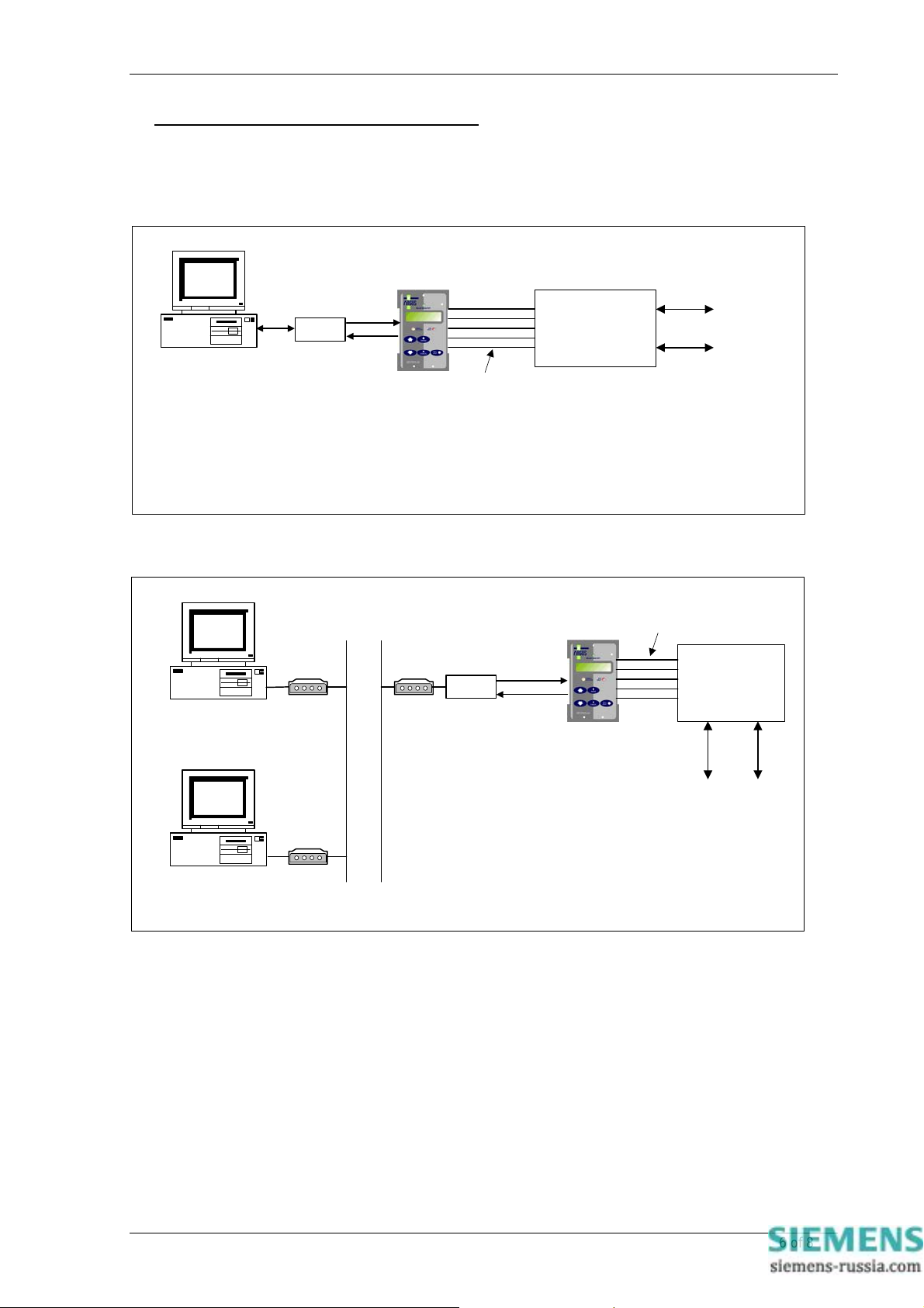
7SG11 Argus 8 Communication Interface
APPENDIX A - COMMUNICATION CONNECTIONS
Figures 1 to 6 illustrate a number of methods of connecting relays in communications networks.
(Note that in the case of the optical ring configuration (figure 5), the Data Echo feature must be switched ON in
the communications settings menu of the relay. In all other cases this setting should be set to OFF).
SIGMA-4
Personal Computer
1. Dialogue type comms (connection oriented)
2. Dialogue for purpose of analogue and digital fault
waveform extraction and display, setting display and change,
event display, instruments etc.
3. Manufacturer specific
Optical link
Parallel hardwired connections
(clean contacts, binary inputs)
Figure 1 - Basic Communications Configuration
Personal Computer
Modem
Modem
P
S
T
N
SIGMA-4
Classical SCADA
Optical link
EMS Remote
Control Points
Parallel hardwired connections
(clean contacts, binary inputs)
Classical SCADA
EMS Remote
Control Points
PSTN : Public Switched Telephone Network
Personal Computer
- Version of the former configuration of Figure 1. It is
necessary to make dial-up connection before actual
information exchange.
Modem
Figure 2 - Basic Communications Configuration (Remote)
©2011 Siemens Protection Devices Limited Chapter 4 Page 6 of 8
Page 48
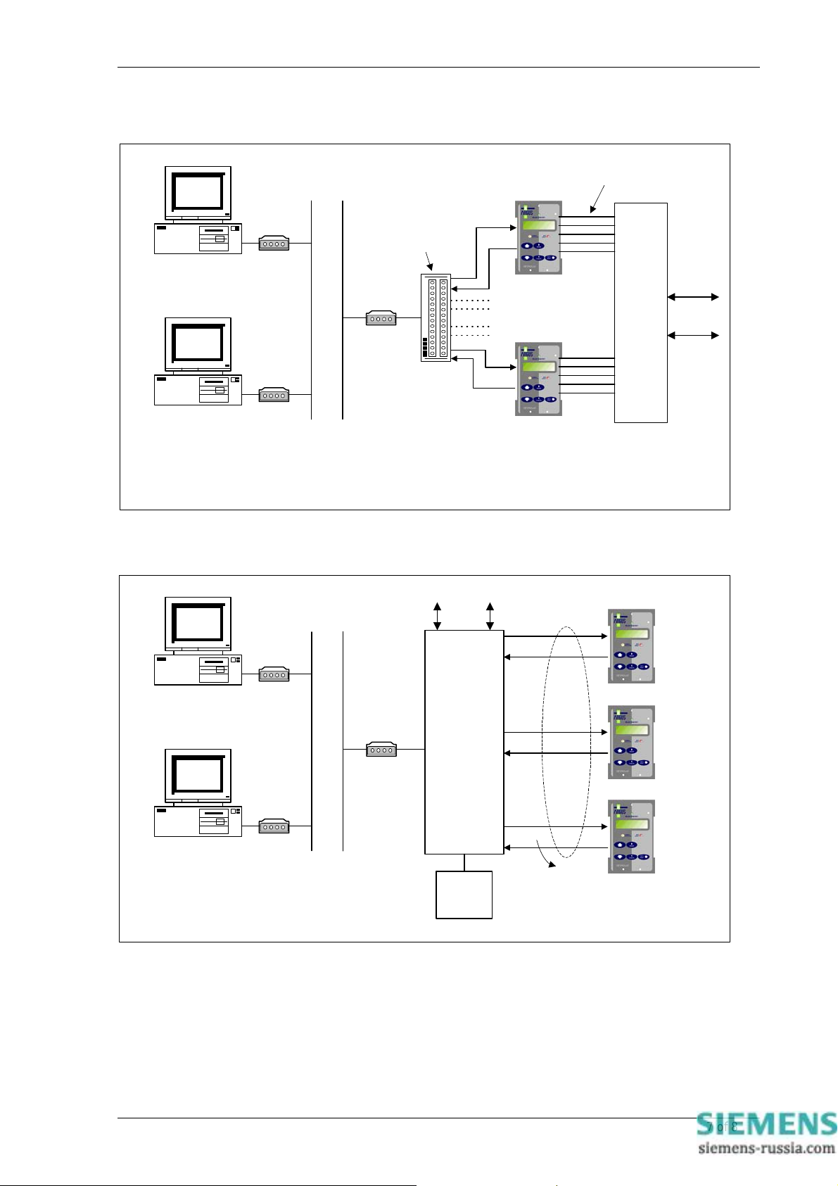
Personal Computer
7SG11 Argus 8 Communication Interface
Parallel hardwired connections
(clean contacts, binary inputs)
PSTN : Public Switched Telephone Network
Fibre-Optic Hub
Multiplexer
Modem
P
S
T
N
Personal Computer
- A more sophisticated version of the former configuration of
Figure 2. Several relays within the substation can be
accessed via one modem but only one can be communicated
with at a time.
Personal Computer
Modem
Figure 3 - Star Type Configuration (Multiplexer)
PSTN : Public Switched Telephone Network
Modem
Modem
P
S
T
N
Modem
SIGMA-1
EMS Remote
Control Points
Data Concentrator /
Control system
Serial optical
links
Tx
Serial optical links
Rx
Tx
Rx
Classical
SCADA
EMS Remote
Control Points
Tx
Personal Computer
- Both Dialogue type and Automatic comms :
- Automatic type : continuous interrogation of all relays by
cyclical polling.
- Dialogue type comms. can be initialised from MMI also
Modem
Man-Machine
Interface
Rx
Cyclical
polling
Figure 4 - Data Concentrator Configuration
©2011 Siemens Protection Devices Limited Chapter 4 Page 7 of 8
Page 49
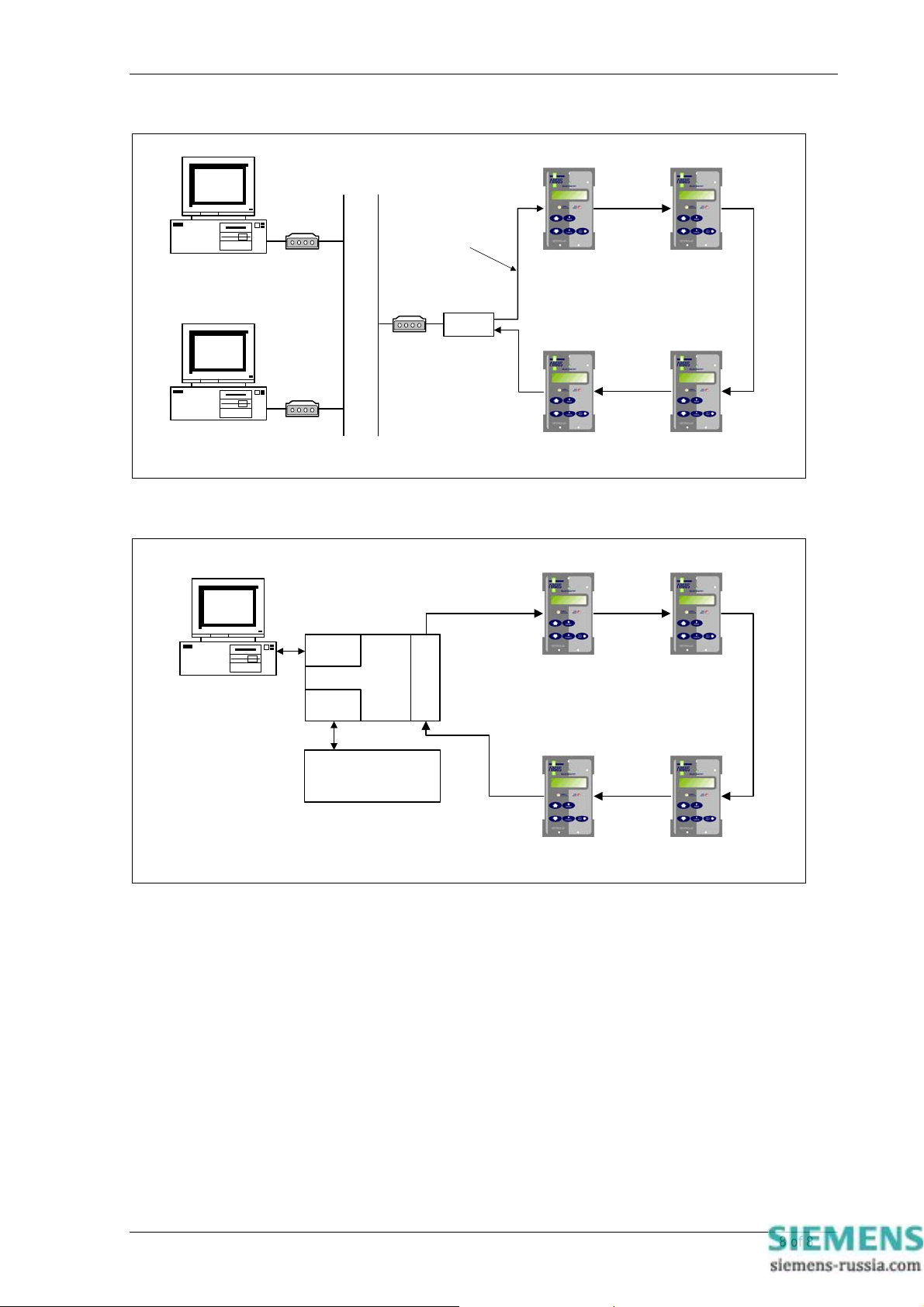
7SG11 Argus 8 Communication Interface
Personal Computer
Personal Computer
Personal Computer
PSTN : Public Switched Telephone Network
Serial optical link
Modem
P
S
T
Modem
N
Modem
Figure 5 - Optical Ring Configuration
Local
RS232
SIGMA-3
System
RS232
Tx
FO
Rx
SIGMA-4
Serial optical
link
Rx Rx
Tx
Rx
Rx Rx
Tx Tx
Tx Tx
TxTx
RxRx
Control System
TxTx
RxRx
Figure 6 - Configuration using the Sigma 3 – Dual Port RS232 Device
©2011 Siemens Protection Devices Limited Chapter 4 Page 8 of 8
Page 50
7SG11 Argus 8 Applications Guide
7SG11 Argus 8
Voltage and Frequency Relays
Document Release History
This document is issue 2010/02. The list of revisions up to and including this issue is:
Pre release
2010/02 Document reformat due to rebrand
Software Revision History
2011/11 2422H80004R7 Fault trigger when the voltage blocking threshold is OFF.
IEC 60870-5-103 fault numbering for fault and its measurands
The copyright and other intellectual property rights in this document, and in any model or article produced from it
(and including any registered or unregistered design rights) are the property of Siemens Protection Devices
Limited. No part of this document shall be reproduced or modified or stored in another form, in any data retrieval
system, without the permission of Siemens Protection Devices Limited, nor shall any model or article be
reproduced from this document unless Siemens Protection Devices Limited consent.
While the information and guidance given in this document is believed to be correct, no liability shall be accepted
for any loss or damage caused by any error or omission, whether such error or omission is the result of
negligence or any other cause. Any and all such liability is disclaimed.
©2011 Siemens Protection Devices Limited
Page 51

7SG11 Argus 8 Applications Guide
Contents
1 Introduction..........................................................................................................................................2
2 General Information.............................................................................................................................2
2.1 Relay External Connections........................................................................................................2
2.2 Voltage Blocking Element............................................................................................................2
2.3 Output Contact Delay Time.........................................................................................................3
2.4 Setting DTL Times.......................................................................................................................3
2.5 Voltage Element Hysteresis........................................................................................................4
2.6 Trip Circuit Supervision ...............................................................................................................4
3 Application of Functions......................................................................................................................4
3.1 Undervoltage Protection..............................................................................................................4
3.2 Overvoltage Protection................................................................................................................5
3.3 Neutral Voltage Displacement Protection....................................................................................5
3.4 NPS Overvoltage Protection........................................................................................................6
3.5 Frequency Protection ..................................................................................................................6
Table of Figures
Figure 1 – Trip Circuit Supervision Scheme........................................................................................8
Figure 2 – 2 Phase-Phase ‘V’ Connection..........................................................................................9
Figure 3 – 2 Phase-Phase Connection.............................................................................................10
Figure 4 – Phase-Phase with Residual Voltage Connection.............................................................11
Figure 5 – 2 Systems Connection (Ph-N)..........................................................................................12
Figure 6 – 3 Phase-Neutral Connection............................................................................................13
Figure 7 – 2 Phase-Phase with Residual Voltage Connection..........................................................14
Figure 8 – 3 Phase-Phase Connection.............................................................................................15
©2011 Siemens Protection Devices Limited Chapter 5 Page 1 of 16
Page 52

7SG11 Argus 8 Applications Guide
1 Introduction
There are numerous applications for the Argus 8 series of relays, which have been developed suitable for
generation, industrial, distribution and transmission systems. This application gui de will illustrate some typical
examples, though actual setting guidelines or recommendations will be limited, as these are very much
system dependent
.
2 General Information
2.1 Relay External Connections
The Argus 8 relay can be configured in many different ways, which usually involve different external
connections to the relay. For phase-neutral and phase-phase connections the relay assumes nominal
63.5V and 110V systems respectively. This does not mean that the relay cannot be applied to nominal
57.7V and 100V systems. For these systems the normal operation of the relay is identical to that of the
63.5 / 110V systems.
Note, however, that if the relay is used in 57.7 / 100V systems and the communications interface is
accessing the relay’s measurand data, any Class 2 measurands will be normalised to 63.5 / 110V
nominal secondary voltages.
Figures 2 through to 7 are typical application diagrams, which show ways o f connecting and using the
relays in different configurations.
2.2 Voltage Blocking Element
The voltage blocking element acts as a block to the Voltage, Frequency and NPS elements in the
relay. If all phase voltages fall below the threshold level then the blocking operation will operate. T his
block does not apply to the NVD elements.
The voltage blocking element performs a number of functions :
1. If the relay has been set up with undervoltage elements enabled and is switched on with no volts
applied to its inputs then, an undervoltage starter would pickup and the relay may issue a trip. The
relay would then stay locked in this trip condition until volts are applied and the element is reset.
To prevent this from happening the voltage blocking threshold has to see volts above its set level
otherwise the relay is fully blocked and no starter or trip operation will follo w.
2. In auto-reclose schemes the voltage blocking threshold can be used to prevent unnecessary
operations of the undervoltage elements during the time when the line is d e-energised. For this
type of blocking operation the threshold is typically set to 20% of rated volts, though it should
always be set to a value above the expected level of induced voltages on t he line.
3. Where the Relay is used in Under / Over Voltage schemes the relay can discriminate between the
condition of a true system Undervoltage which exists for some time i.e. a progressive reduction in
system voltage, caused by increase in loading or due to switching or as a result of problems with
tap changers, and for which a Trip output must be given; or, the condition of an Undervoltage due
to loss of system voltage due to an upstream circuit breaker being opened which results in a rapid
voltage collapse to a much lower voltage, this voltage value being determined by coupling from
parallel lines or grading capacitors across series break contacts in Circuit Breakers, and for which
it may not be desirable for a Trip to be issued, note that resultant differential coupling voltages may
also cause the NPS Element threshold to be exceeded and the NPS element to operate. Setting
the Voltage Blocking Threshold to a setting above the expected induced dead-line voltage causes
the Undervoltage block to be raised to inhibit U/V & NPS elements to prevent unwanted Trips /
alarms from being generated.
The Voltage Blocking Threshold setting should be set either to the minimum setting of 1 volt or to a
value graded above the expected dead-line voltage.
In schemes where detection and Alarm /Trip outputs for absolute zero volts is also required the
UnderVoltage Block output ‘ V Block Alarm ‘ should be mapped to the relevant output relay(s). If a
Time delay is needed then the output relay should be connected to a Status input to make use of its
Pick-up and Drop-off time delays.
©2011 Siemens Protection Devices Limited Chapter 5 Page 2 of 16
Page 53
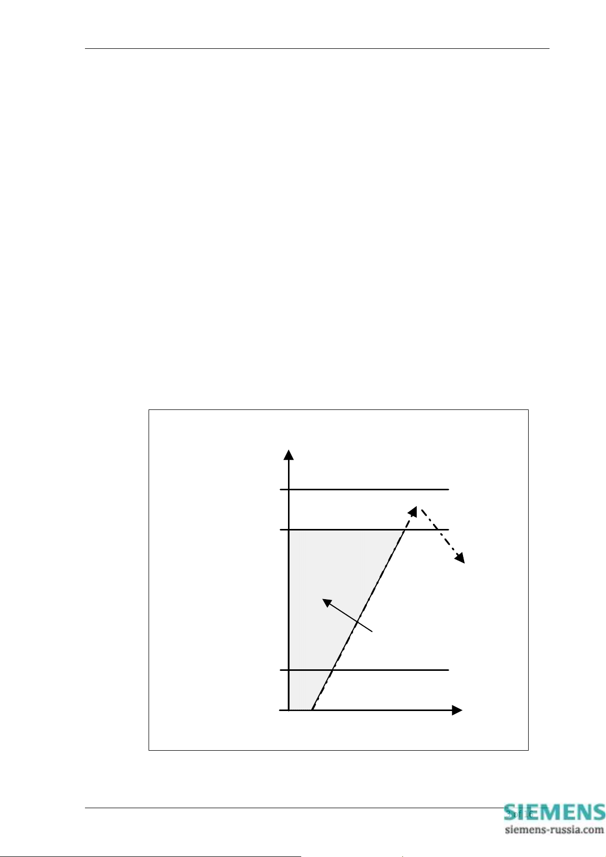
7SG11 Argus 8 Applications Guide
2.3 Output Contact Delay Time
The output relay contacts have a typical close response time of 7ms.This inherent dela y is not,
however, the only factor determining the actual contact closure time. The relay has a main software
control loop of 10ms. Any software decision or external interrupt to the microcontroller involves a
maximum possible delay of 10ms while the software completes the loop. This time should be added to
the contact closure time of 7ms to give a maximum response time.
e.g. - if an energisation signal is applied to a status input which is programmed to directly operate an
output relay the following delays should be added:
Status I/P response time (< 5ms) + Status PU delay setting + S/W loop (max. 10ms) + O/P contact
closure (typically 7ms).
This gives a total time of < 22ms + Status PU delay setting.
2.4 Setting DTL Times
When applying a DTL timer with any of the protection elements the instantaneous operate time of the
element will have to be determined so that the overall required time delay can be set.
Total Delay Time = Instantaneous Operate Time + DTL Time
The performance specification - Section 2 of this manual gives typical instantaneous operate times for
all of the different characteristics. The instantaneous operate time of an under voltage ele m ent for
example can vary between < 65ms to about 47ms at its fastest. This variation is due to the level of
applied undervoltage and is in fact a function of the method of calculation.
Note that the instantaneous operate time of an undervoltage element is marginally slower than that for
an equivalent overvoltage element. This is because the undervoltage element is deliberately ‘slugged’
so that, when nominal voltage is applied, the RMS calculation has time to ramp up to the correct level
without issuing an invalid trip during the ramp up sequence. This is shown in the diagram below:
Nominal Volts
U/V Setting
V block
Threshold
0V
Volts
RMS
ramp-up
Operate
U/V elemen t will
not operate in this
region
time
©2011 Siemens Protection Devices Limited Chapter 5 Page 3 of 16
Page 54

7SG11 Argus 8 Applications Guide
2.5 Voltage Element Hysteresis
Each under and over voltage element has a variable hysteresis setting which allows the user to alter
the pick-up / drop-off ratio (or drop-off / pick-up ratio) of the element. Note that the NPS, NVD and
frequency elements have fixed levels of hysteresis which are not adjustable.
When using the variable hysteresis, care has to be taken to ensure that with undervoltage elements,
the reset level of the element is not set to a value higher than that at which the system rated voltage is
expected to operate. The system rated voltage will have a tolerance of typically +/- 6% and so the
upper level of the hysteresis must be below the lower limit of the tolerance, otherwise the element
might not reset in practice. Conversely, the level of hysteresis set for an overvoltage element should
not be set below that at which the system rated voltage is expected to run.
Typical values for the amount of hysteresis applied to a voltage element are < 5%. When setting the
hysteresis level the user has to be aware that if the amount of hysteresis is set too low e.g. 1%, then
for large frequency excursions and low values of voltage element setting, the element might becom e
unstable and ‘chatter’. This will produce nuisance alarms / tripping and generate large nu m bers of
stored event records. A minimum recommended level is 2% for this reason.
2.6 Trip Circuit Supervision
Argus relay can be used to supervise trip circuits while the associated circuit breaker (CB) is either
open or closed. A low value of dc current, derived from the auxiliary supply, is passed through the
entire trip circuit to monitor the trip coil, its auxiliary switch, the CB secondary isolating contacts and the
relevant wiring. If the current flow ceases, the energised status input drops off and if it is userprogrammed to operate one of the output relays, this relay will close an output contact to signal trip
circuit failure. In addition, the LCD display on the Argus relay will indicate ‘Trip Circuit Fail’.
To avoid giving spurious alarm messages while the CB is operating, or protection device on adjac ent
supply circuits is operating, the status input should be programmed to have a 500ms drop-off delay.
The Electricity Association H6 Scheme is shown in Figure 1.
3 Application of Functions
3.1 Undervoltage Protection
Undervoltages are reasonably frequent events on power systems and can occur for a number of
different reasons. Faults on the system can cause the phase voltages to be depressed, the actual
voltage drop being dependent upon a number of factors including the fault type and system earthing
etc. During system earth fault conditions, the undervoltage protection is not generally required to
operate and thus connecting the relay in the phase-phase configuration will make it less susceptible to
single-phase voltage depressions.
Another cause of undervoltage is an increase in system loading, which should be corrected by system
regulating equipment such as tap-changers and AVR’s. However, if this equipment is defective then an
undesirable situation will occur which will require an undervoltage relay to trip non-essential loads to
correct for this voltage excursion and to bring it back to its nominal level. This tripping should happen
after an appropriate time delay has expired. Generally, wherever voltage relays are employed, timing
elements should be used to prevent operation during transient disturbances.
If the system is supplying 3-phase induction motors or variable frequency thyristor drives,
undervoltages can have the following effect. Voltage depressions down to approximately 80% of rated
voltage cause the load current to increase, possibly resulting in a larger voltage depression due to the
supply source impedance. Below 80% the current drawn is proportional to the voltage and an induction
motor is likely to stall. The current drawn is then dependent on the drive design e.g. thyristor drives
include current limitation. An undervoltage element can be set to trip out a motor circuit when the
voltage falls below a preset value, selected based on the motor drive and system design parameters,
and after a preset time delay. The time delay is required to ensure voltage dips due to remote system
faults do not result in an unnecessary trip.
If the system supply to a group of motors is lost, undervoltage protection can be applied to ensure that
each of the motor circuit breakers or contactors are tripped so that on restoration of the main supply, it
is not overloaded by the simultaneous starting of all the motors. A 3-phase undervoltage relay may be
used for this task of tripping a feeder for the detection of a complete loss of voltage. Also, where a
supply to induction motors is lost, the undervoltage relay can be used to detect the loss of supply or to
©2011 Siemens Protection Devices Limited Chapter 5 Page 4 of 16
Page 55

7SG11 Argus 8 Applications Guide
monitor any busbar residual voltage e.g. resulting from back e.m.f. generated by the induction motors
as they run down. The relay can act as a guard prior to re-connecting a supply from an alternative
source.
Where undervoltage relays are used on a system, the voltage eleme nts should be set to a value below
that where a normal system voltage excursion can be expected. (See also section 2.5). Typically the
set values may be of the order of 65-80% of nominal for protection of the system or plant. For
confirmation that a monitored supply is ‘dead’ or that any residual voltage has reduced to a safe level,
typical set values should be of the order of 10-30% of nominal voltage.
3.2 Overvoltage Protection
Overvoltages may be caused for a number of different reasons. On generator sets for example, it may
be caused by defective operation of the voltage regulator, or, if there is a sudden loss of load due to
line tripping. Under this load rejection situation the generator set may overspeed causing a dangero us
voltage rise. This should be corrected by system regulating equipment such as tap changers and
AVR’s, but if this equipment mal-functions then voltage levels may rise. High levels of overvoltages on
a system cannot be sustained for long periods because they can cause damage to the system
insulation and severely affect the life of the insulation. An overvoltage element with an appropriat e DTL
time delay setting to allow for the normal system regulating equipment to operate can be used to
protect against this type of condition.
With a maximum of four overvoltage elements available, the Argus 8 relay can provide for a variety of
different applications. If the overvoltage condition is only small a relatively long DTL time delay can be
set on an element to clear the fault. If the overvoltage is more severe then another element, set at a
higher pickup level and with a faster DTL time, can be used to clear the fault more quickly.
Alternatively, elements can be set to provide alarm and tripping stages, with the alarm levels set lower
than the tripping stages.
Note - the use of instantaneous and wide ranging DTL settings allows a simple and secure grading
system to be applied to co-ordinate the network design, the regulating plant design and system plant
insulation withstand. The use of IDMTL protection is not recommended because of the difficulty of
choosing settings to ensure correct co-ordination and security of supply.
Generally, wherever voltage relays are employed, timing elements should be used to prevent operation
during transient disturbances. Also, overvoltage relays must be co-ordinated with other overvoltage
relays elsewhere on the system
.
3.3 Neutral Voltage Displacement Protection
The three phases of a balanced healthy system summate to zero. When a single-phas e earth fault
occurs, the system balance is upset and a ‘residual’ voltage is produced. The residual voltage is
therefore a means of detecting earth fault conditions without any measurement of current. This may be
essential for high impedance earthed or insulated systems where it might not be viable to provide core
balance CT’s on each feeder.
The residual voltage can be measured at the secondary terminals of a VT havin g an ‘open delta’
secondary connection. The VT must be a standard five limb type or three single phase VT’s can be
used. This is because the residual voltage is three times the zero sequence voltage and therefor e zero
sequence flux has to flow in the core. For this to happen there must be a return path for the resultant
summated flux and this occurs on a five limb type because the outer limbs are unwound. Where three
single phase VT’s are used, each phase unit has a core with a closed magnetic circuit. A three limb VT
is not suitable for this application because there is no magnetic path, through the core, which the zero
sequence flux can flow.
Another requirement for the VT is that the primary winding neutral has to be earthed. Without this, an
earth zero sequence exciting current cannot flow. Figures 4 and 7 are typical connection diagrams
showing the two versions of relay with a residual voltage connection to a five limb VT.
Internally the relay performs a zero sequence calculation, which is multiplied by 3 to derive the residual
voltage. (The actual residual voltage element setting is referred to as 3Vo). Note that the ‘Vo’
instrument in the ‘Instruments Display Menu’ displays the zero sequence voltage regardless of whether
the residual voltage is directly measured or calculated internally. The actual system residual voltage is
three times the indicated Vo reading.
The output voltage of the open delta winding can contain triplen harmonics, with the 3rd being the most
predominant. These triplen harmonics appear across the open delta windin g even when there is no
earth fault on the network and no zero sequence voltage. The relay’s main measuring algorithm being
©2011 Siemens Protection Devices Limited Chapter 5 Page 5 of 16
Page 56

7SG11 Argus 8 Applications Guide
based upon a DFT, coupled with the anti-aliasing filter in the input stage, ensures that any 3rd harmonic
present is heavily attenuated and will not cause a mal-trip.
Where a power transformer delta or unearthed star winding is connected to a transformer feeder it is
essential to ensure that this unearthed winding cannot remain energised under system earth-fault
conditions. This condition will result in danger to life and possible hazard to the sound phases due to
intermittent arcing via system earth capacitance. Initiation of tripping may be by means of a neutral
displacement relay arranged to detect residual voltage to earth at the transformer using either a voltage
transformer or coupling capacitors. The relay will operate for external as well as internal feeder faults
and must, therefore, be provided with a time delay to ensure discrimination.
The NVD protection in the relay consists of 2 independent stages which can be used for alarm and trip
purposes. Each has a user settable DTL time delay element associated with it. These are useful for
applications such as insulated systems where, following an earth fault, the phase voltages may have to
withstand sustained overvoltages. An alarm from the first stage can be issued after a short delay to
indicate that there is an earth fault on the system. If this is not satisfactorily cleared then the second
stage can issue a trip signal to isolate the fault.
3.4 NPS Overvoltage Protection
Unbalanced voltage on 3-phase network results as a consequence of unbalanced load current caus ing
unequal voltage drops in network impedances. The unbalanced load current could be the result of
single phase open circuits (isolator failures, broken conductors etc.), or because of loads generatin g
harmonics (e.g. thyristor drives). Unbalanced voltage generated at a busbar has the knock-on effect of
causing healthy balanced loads to become unbalanced.
In the case of generators, unbalanced loading causes negative phase sequence (NPS) currents in the
generator stator, which induces double frequency currents in the rotor causing heating of the machine.
If the NPS current exceeds the limit of the generator, protection on the generator will operate and could
result in all the generators connected being tripped. Induction motors also are vulnerable to NPS
current and again, as for generators, NPS overcurrent protection is provided and included on the
majority of industrial plant motors.
The NPS or unbalanced voltage function in the Argus 8 relay can be employed to monitor the quality of
the 3-phase ac supply and thus provide early warning of developing problems of NPS currents, which
might cause tripping of generators or motors. In this respect the NPS overvoltage protection is very
beneficial.
The NPS protection consists of 2 independent stages, each with a user settable DTL time del ay
element associated with it. These can be used for both alarm and tripping purposes.
Where the 3-phase VT’s supplying an Argus 8 relay are protected by fuses, special consideration has
to be made. Any single fuse operating e.g. due to ageing or a winding / wiring fault, will result in NPS
voltage in the input to the relay. Where miniature circuit breakers (MCB’s) are employed they can be
provided with an “all phases trip” feature which prevents the mal-operation of an NPS voltage
monitoring relay. (An “all phases trip” MCB will operate for any fault condition). However, where fuses
are employed, allowance must be made for the impact of a single fuse operation. If the NPS
overvoltage function of the relay is used only for alarm purposes, there is no serious consequence. If,
however if it used for delayed tripping, then consideration should be given to blocking for single fuse
failure. One method is to use the two separate NPS stages, one set as a high set instantaneous for
blocking a trip and the other as a lower set, time delayed stage for protection of the rotating plant.
However, a problem arises in that a broken primary circuit phase has a similar effect to single fuse
operation. The preferred solution is to provide MCB’s with an “all phases trip” feature for the secondary
circuit protection.
3.5 Frequency Protection
When a power system is in stable operation at normal frequency, the total mechanical power input from
the prime movers to the generators is equal to the sum of all the connected loads, plus all real power
losses in the system. Any frequency variation is an indication of generator-load imbalance in the
system. If an interconnected system splits, for example, there might be a situation where the load in
one of the subsystems is in excess of the generator capacity in that subsystem. In this instance the
generator speed will begin to decrease causing a proportional frequency drop. An underfrequency
condition at nominal voltage can lead to over-fluxing of plant such as generators and transformers. If
the governors and other regulating equipment cannot respond quickly enough, a sustained
underfrequency condition may lead to a system collapse. Conversely, if there is an exces s of
generation in the subsystem then the generator speed will increase causing a proportional frequency
©2011 Siemens Protection Devices Limited Chapter 5 Page 6 of 16
Page 57

7SG11 Argus 8 Applications Guide
rise. This may be unacceptable to industrial loads, for example, where the running speeds of
synchronous motors will be affected.
In the situation where the system frequency is collapsing rapidly it is common practise to disco nnect
non-essential loads for short periods of time, until the generation-load requirements and network
configuration can be corrected. This is designed to preserve system integrity and minimise outages.
Normally utilities will avoid intentionally interrupting service, but in this case non-critic al loads can be
interrupted for short periods. This type of scheme is known as an underfrequency load shedding
scheme. Usually, automatic load shedding, based on underfrequency, is necessary since sudden,
moderate-to-severe frequency shifts can throw a system into a dangerous state much faster than an
operator can react. Underfrequency relays are usually installed at distribution substations, or industrial
plant, where selected loads can be disconnected and where similar priority l oads are often grouped
together
The object of load shedding is to re-establish the generator-load equation. At the instant of a
disturbance a measure of the amount of overload is not readily available and thus load is shed in
stages until the frequency stabilises and returns to within the nominal band. An example scheme would
have the first load shedding stage set just below the nominal frequency, e.g. between 49.0 - 49.5Hz. A
time delay element would be associated with this and this would be set to allow for transient dips in
frequency, as well as to provide a time for the system regulating equipment to respond. The first load
shedding stage would be set to shed a significant percentage of the system load. If this drop is
sufficient, the frequency will stabilise and perhaps increase and return to nominal. If, however, this is
not sufficient then a second load shedding stage, set at a lower frequency, will now shed a small er
percentage of load until the overload is relieved. This process will continue until all stages have
operated. In the event of the load shedding being unsuccessful, a final stage of underfrequency
protection should be provided to totally isolate all loads before plant is damaged, e.g. due to
overfluxing.
An alternative type of load shedding scheme would be to set all underfrequency stages to about the
same frequency setting but to have different length time delays set on each stage. If after the first stage
is shed the frequency doesn’t recover then subsequent stages will shed after longer time delays have
elapsed.
As has been mentioned earlier, where there is an excess of generation in a subsystem the frequency
will rise. This is most commonly due to loss of load situations, which cause the generators to speed up.
Normally the generator control equipment will respond to regain the normal running speed, but if this
equipment fails then the overfrequency protection can be used as a b ackup . The settings for the
overfrequency elements should be set to allow for transient frequency excursions following a loss of
load condition and allow time for the generator control systems to recover the situation.
The Argus 8 relay has four frequency elements, each of which can be set for underfrequency
operation. These, coupled with independent voltage elements and a large number of output contacts
available, enable economic application for complex load shedding sch emes. The accuracy and security
of operation built into the numeric algorithms makes them ideally suited for this type of application. All
frequency elements can be blocked in a number of different ways. Section 1 - 3.5 of this manual
describes the ways in which this can be achieved. It is important to note that where there is other load
shedding equipment on a system, the Argus 8 relay should be set to co-ordinate with it.
.
©2011 Siemens Protection Devices Limited Chapter 5 Page 7 of 16
Page 58
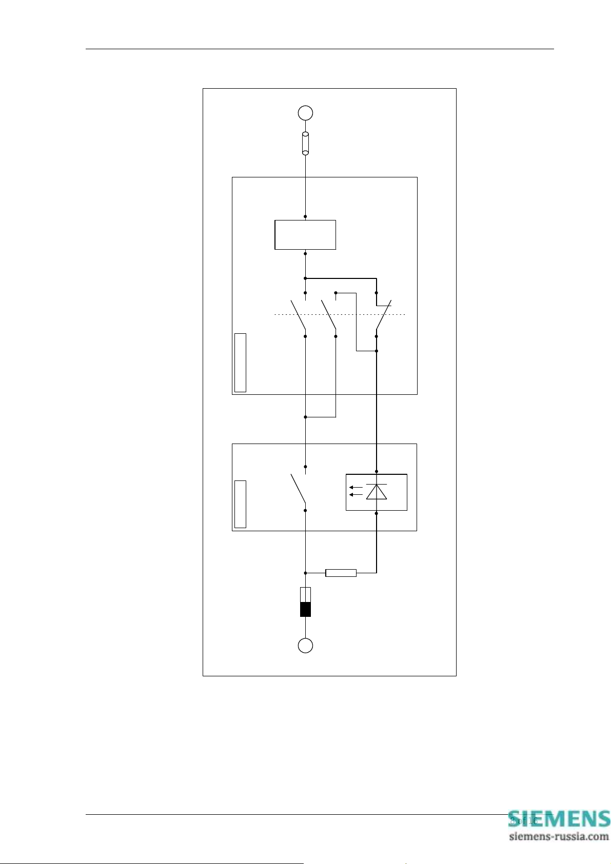
Circuit Breaker
Auxiliary
Trip Coil
Contacts
Auxiliary
7SG11 Argus 8 Applications Guide
Supply
Link
Argus Relay Circuit Breaker
Trip Relay Contact
Fuse
Auxiliary
Supply
+ -
Status Input
For 110/125Vdc
use external 2K7
dropper resistor
Figure 1 – Trip Circuit Supervision Scheme
ELECTRICITY ASSOCIATION H6 SCHEME
©2011 Siemens Protection Devices Limited Chapter 5 Page 8 of 16
Page 59
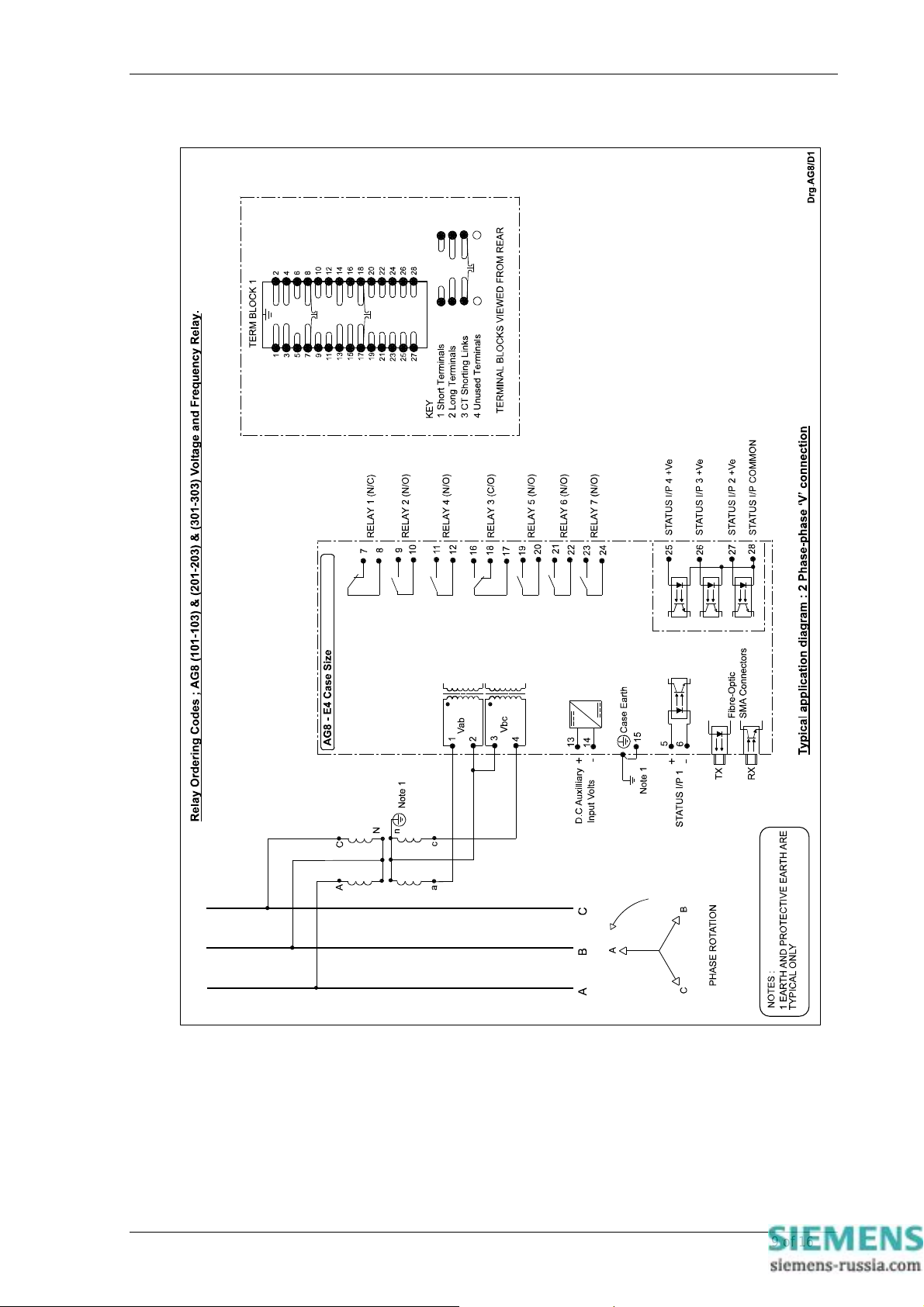
7SG11 Argus 8 Applications Guide
Figure 2 – 2 Phase-Phase ‘V’ Connection
©2011 Siemens Protection Devices Limited Chapter 5 Page 9 of 16
Page 60
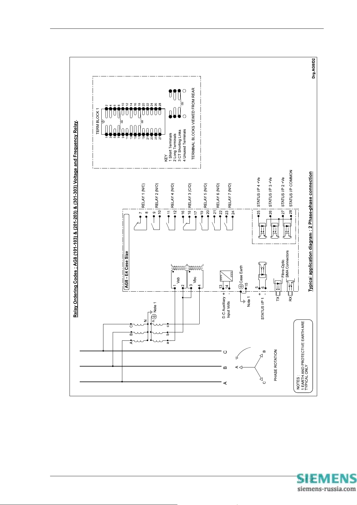
7SG11 Argus 8 Applications Guide
Figure 3 – 2 Phase-Phase Connection
©2011 Siemens Protection Devices Limited Chapter 5 Page 10 of 16
Page 61
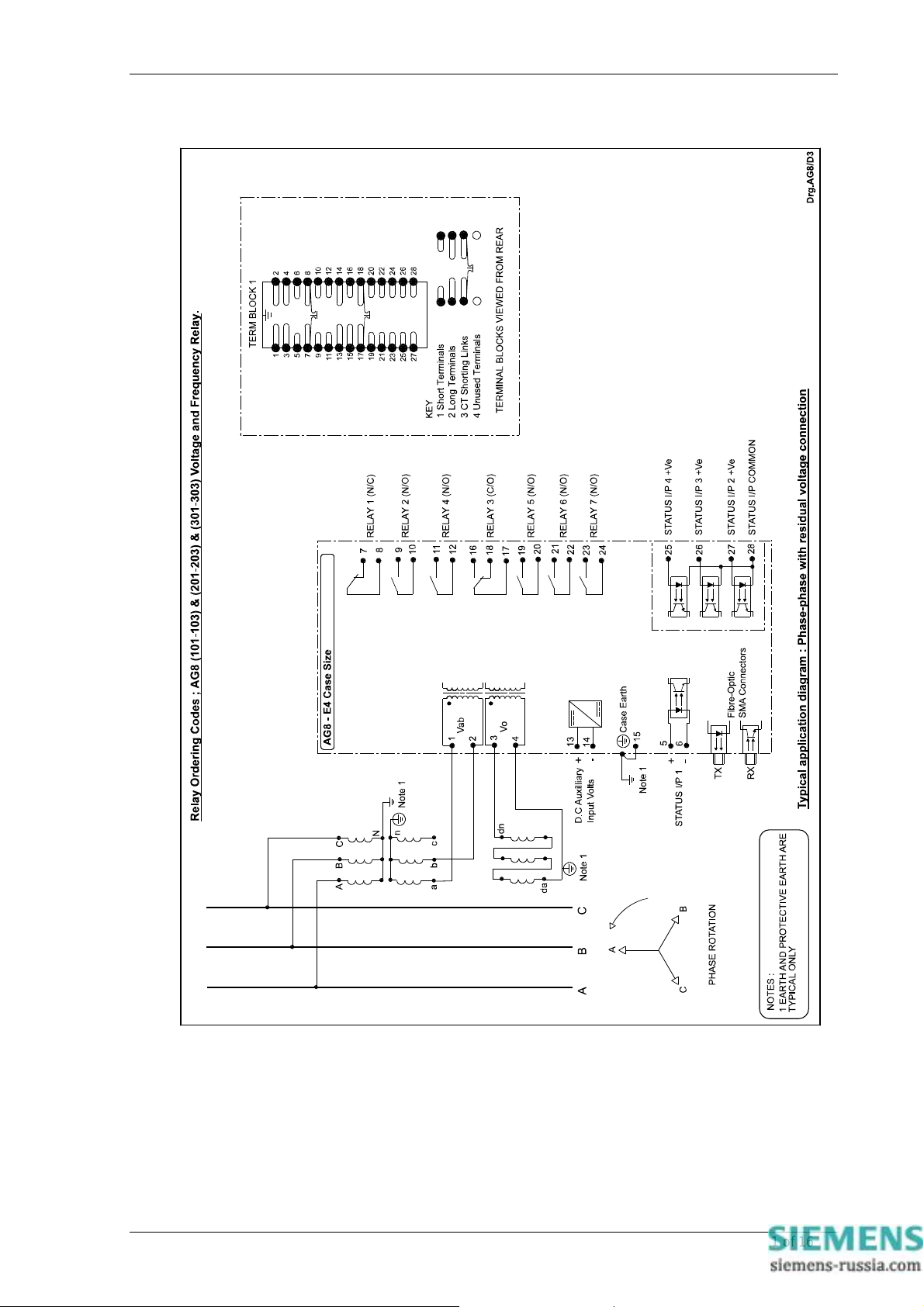
7SG11 Argus 8 Applications Guide
Figure 4 – Phase-Phase with Residual Voltage Connection
©2011 Siemens Protection Devices Limited Chapter 5 Page 11 of 16
Page 62
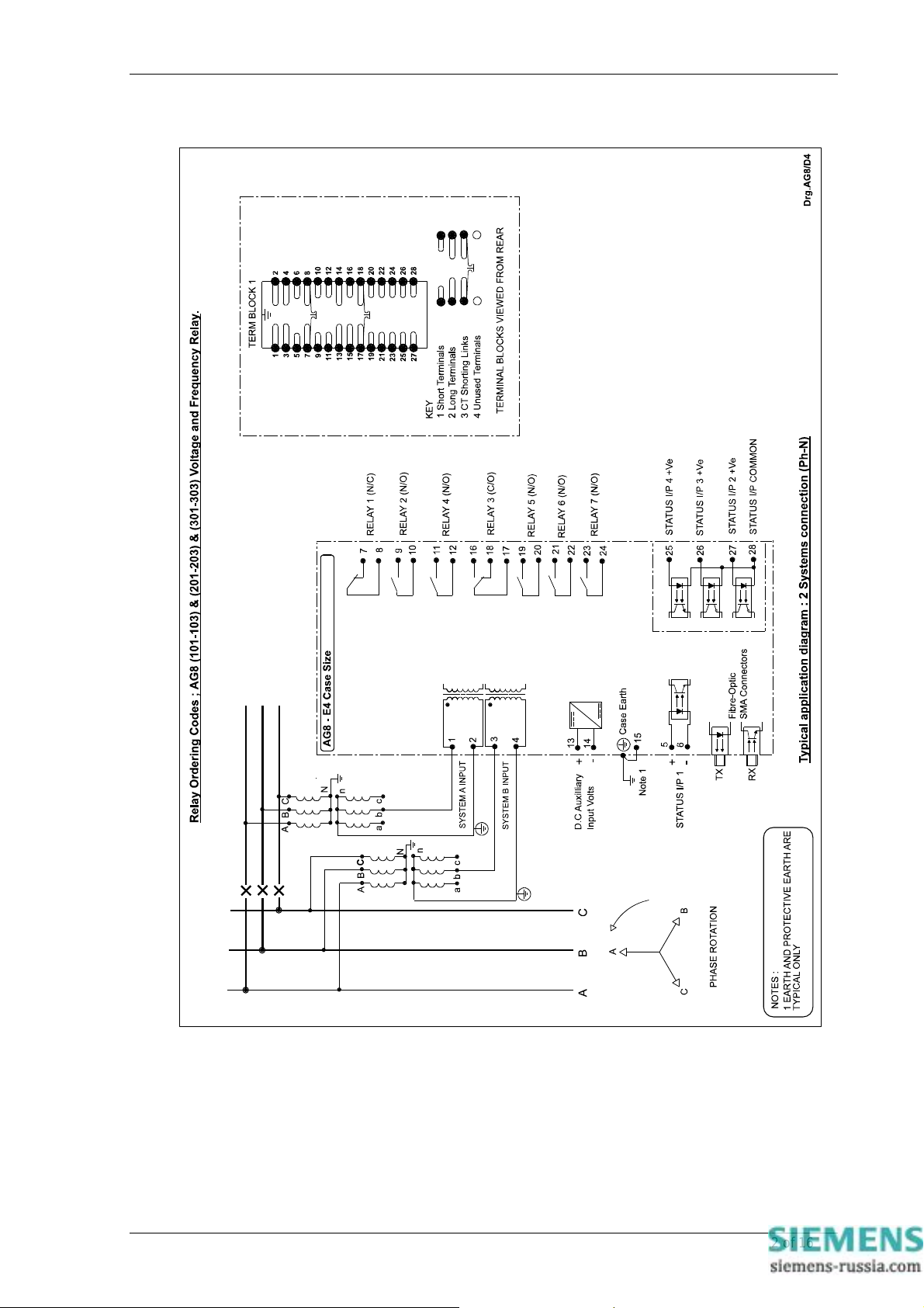
7SG11 Argus 8 Applications Guide
Figure 5 – 2 Systems Connection (Ph-N)
©2011 Siemens Protection Devices Limited Chapter 5 Page 12 of 16
Page 63
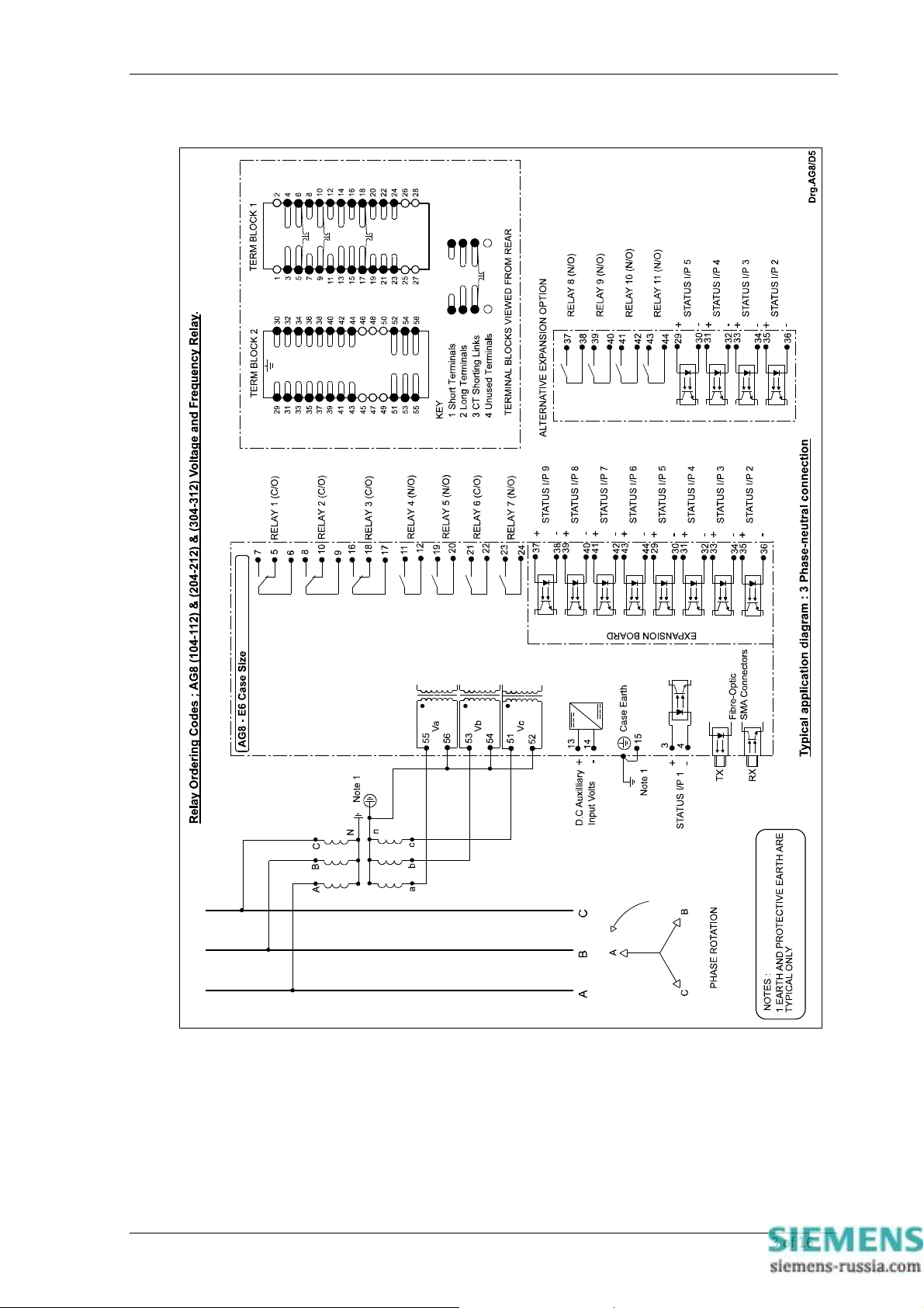
7SG11 Argus 8 Applications Guide
Figure 6 – 3 Phase-Neutral Connection
©2011 Siemens Protection Devices Limited Chapter 5 Page 13 of 16
Page 64
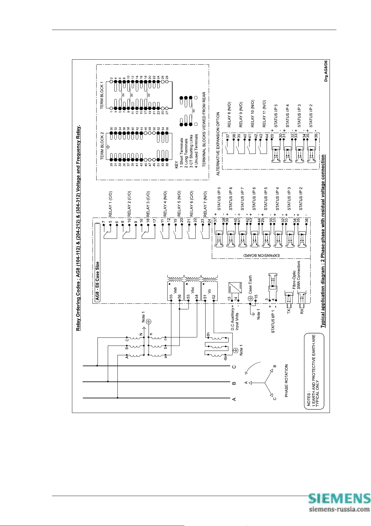
7SG11 Argus 8 Applications Guide
Figure 7 – 2 Phase-Phase with Residual Voltage Connection
©2011 Siemens Protection Devices Limited Chapter 5 Page 14 of 16
Page 65
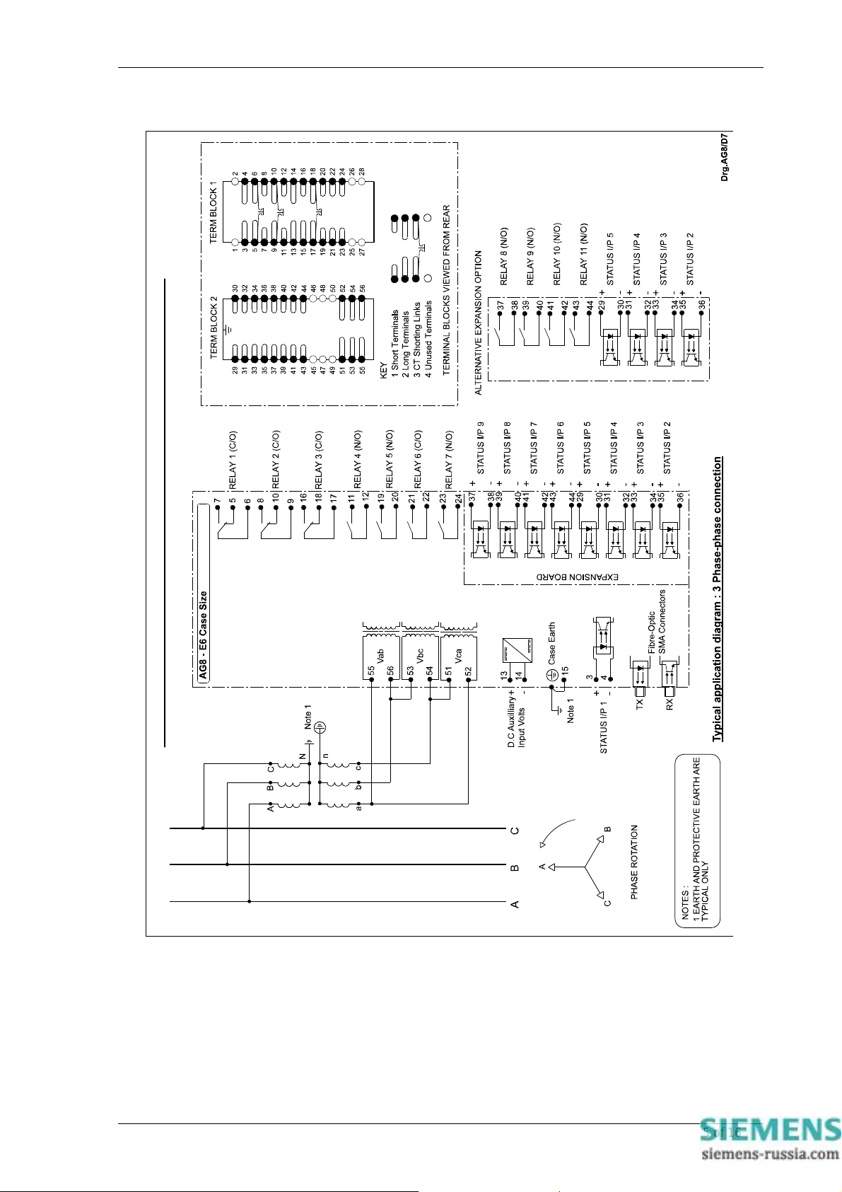
7SG11 Argus 8 Applications Guide
Relay Ordering Codes ; AG8 (104-112) & (204-212) & (304-312) Voltage and Frequency Relay.
Figure 8 – 3 Phase-Phase Connection
©2011 Siemens Protection Devices Limited Chapter 5 Page 15 of 16
Page 66
7SG11 Argus 8 Installation
7SG11 Argus 8
Voltage and Frequency Relays
Document Release History
This document is issue 2010/02. The list of revisions up to and including this issue is:
Pre release
2010/02 Document reformat due to rebrand
Software Revision History
2011/11 2422H80004R7 Fault trigger when the voltage blocking threshold is OFF.
IEC 60870-5-103 fault numbering for fault and its measurands
The copyright and other intellectual property rights in this document, and in any model or article produced from it
(and including any registered or unregistered design rights) are the property of Siemens Protection Devices
Limited. No part of this document shall be reproduced or modified or stored in another form, in any data retrieval
system, without the permission of Siemens Protection Devices Limited, nor shall any model or article be
reproduced from this document unless Siemens Protection Devices Limited consent.
While the information and guidance given in this document is believed to be correct, no liability shall be accepted
for any loss or damage caused by any error or omission, whether such error or omission is the result of
negligence or any other cause. Any and all such liability is disclaimed.
©2011 Siemens Protection Devices Limited
Page 67

7SG11 Argus 8 Installation
Contents
1 Unpacking, storage and handling........................................................................................................3
2 Recommended mounting position.......................................................................................................3
3 Relay dimensions................................................................................................................................3
4 Fixings.................................................................................................................................................3
4.1 Crimps .........................................................................................................................................3
4.2 Panel Fixing Screws....................................................................................................................3
4.3 Communications..........................................................................................................................4
5 Ancillary equipment.............................................................................................................................4
Table of Figures
Figure 1 - Overall dimensions of E4 case ...........................................................................................5
Figure 2 - Overall dimensions of E6 case ...........................................................................................6
©2011 Siemens Protection Devices Limited Chapter 6 Page 2 of 6
Page 68
7SG11 Argus 8 Installation
1 Unpacking, storage and handling
On receipt, remove the relay from the container in which it was received and inspect it for obvious damage.
Check that the relay is the correct model number and the rating information is correct. It is recommended that
the relay is not removed from the case. To prevent the possible ingress of dirt, the sealed polythene bag
should not be opened until the relay is to be used. If damage has been sustained a claim should immediately
be made against the carrier and Siemens Protection Devices Limited and the nearest Siemens agent should
be informed, using the Defect Report Form in the Maintenance section of this manual.
When not required for immediate use the relay should be returned to its original carton and stored in a clean,
dry place. The relay contains static sensitive devices, which are susceptible to damage due to static discharge
and for this reason it is essential that the correct handling procedure is followed. The relays’ electro nic circuits
are protected from damage by static discharge when it is housed in its case. When it has been withdrawn
from the case, static handling procedures should be observed.
• Before removing the relay fro m its case the operator must first ensure that he is at the same potential as
the relay by touching the case.
• The relay must not be ha ndled by any of the relay terminals on the rear of the chassis.
• Relays must be packed for transport in an anti-static container.
• Ensure that anyone else h andling the relays is at the same potential as the relay.
As there are no user serviceable parts in the relay, then there should be no requirement to remove any
modules from the chassis. If any modules have been removed or tampered with, then the guarantee will be
invalidated. Reyrolle Protection reserves the right to charge for any subsequent repairs.
2 Recommended mounting position
The relay uses a liquid crystal display (LCD) which displays setting and metering information. It has a viewing
angle of ± 70º and an internal back light. The recommended viewing position is at eye level.
The relay should be mounted onto the circuit breaker or panel at a level which allows the user easiest access
to the relay functions.
3 Relay dimensions
The relay is supplied in either the Epsilon size E4 case or E6 case. Mechanical diagrams of the case
dimensions and panel cut-out requirements are shown in Figures 1 and 2 respectively.
4 Fixings
4.1 Crimps
Amp Pidg or Plasti Grip Funnel entry ring tongue
Size AMP Ref Reyrolle Ref
0.25-1.6mm2 342103 2109E11602
1.0-2.6mm2 151758 2109E11264
4.2 Panel Fixing Screws
Kit – 2995G10046 comprising :
• Screw M4 X10TT 2106F14010 – 4 off
• Lock Washers 2104F70040 – 4 off
• Nut M4 2103F11040 – 4 off
©2011 Siemens Protection Devices Limited Chapter 6 Page 3 of 6
Page 69

7SG11 Argus 8 Installation
4.3 Communications
ST fibre optic connections – 2 per relay.
(Refer to Section 4 of this manual – Communications Interface).
5 Ancillary equipment
The relay can be interrogated locally or remotely by making connection to the fibre optic terminals on the rear
of the relay. For local interrogation a portable PC with a fibre to RS232 modem (Sigma 4) is required. The PC
must be capable of running Microsoft Windows Ver 3.1 or greater, and it must have a standard RS232 port in
order to drive the modem. For remote communications more specialised equipment is required. Refer to
Section 4 of this manual – Communications Interface.
©2011 Siemens Protection Devices Limited Chapter 6 Page 4 of 6
Page 70
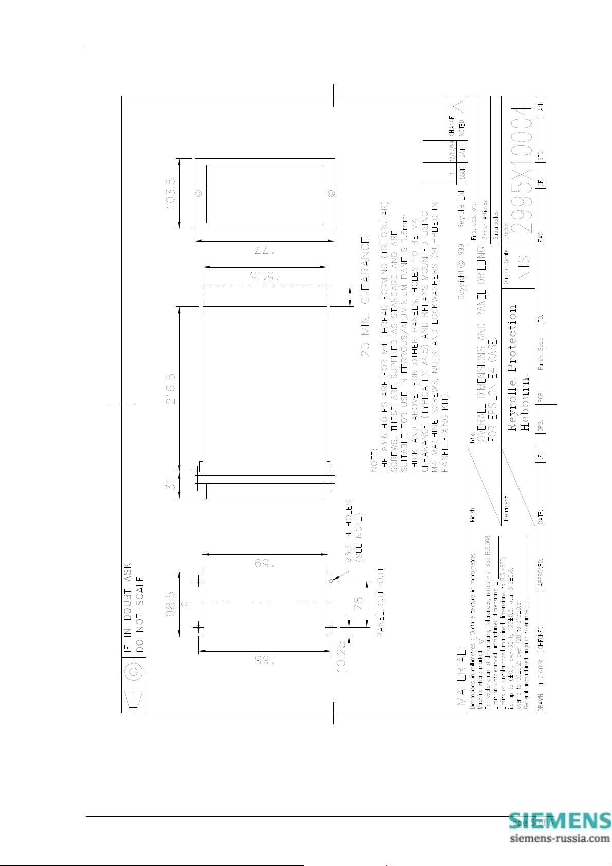
7SG11 Argus 8 Installation
Figure 1 - Overall dimensions of E4 case
©2011 Siemens Protection Devices Limited Chapter 6 Page 5 of 6
Page 71
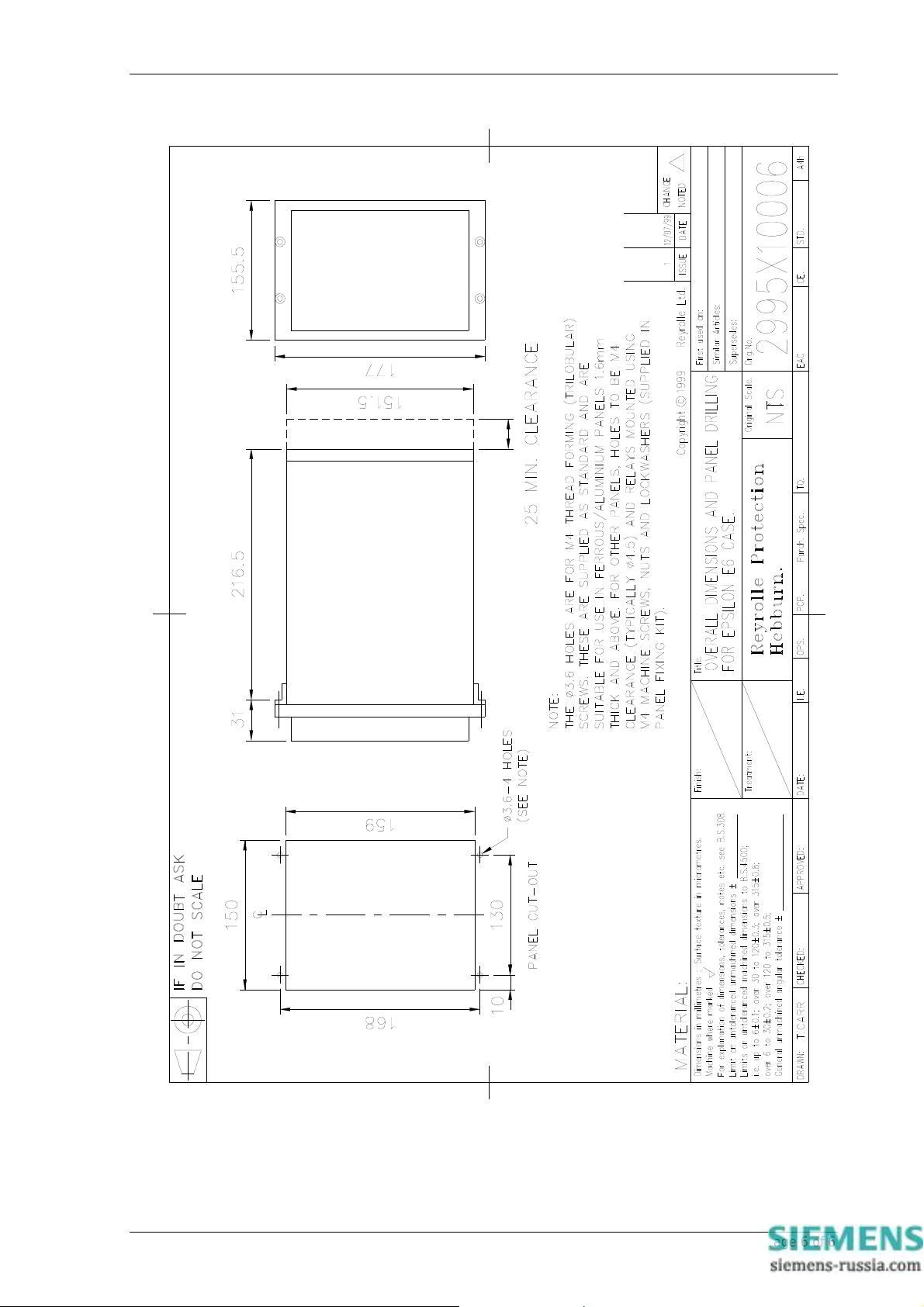
7SG11 Argus 8 Installation
Figure 2 - Overall dimensions of E6 case
©2011 Siemens Protection Devices Limited Chapter 6 Page 6 of 6
Page 72
7SG11 Argus 8 Commissioning
7SG11 Argus 8
Voltage and Frequency Relays
Document Release History
This document is issue 2010/02. The list of revisions up to and including this issue is:
Pre release
2010/02 Document reformat due to rebrand
Software Revision History
2011/11 2422H80004R7 Fault trigger when the voltage blocking threshold is OFF.
IEC 60870-5-103 fault numbering for fault and its measurands
The copyright and other intellectual property rights in this document, and in any model or article produced
from it (and including any registered or unregistered design rights) are the property of Siemens Protection
Devices Limited. No part of this document shall be reproduced or modified or stored in another form, in any
data retrieval system, without the permission of Siemens Protection Devices Limited, nor shall any model or
article be reproduced from this document unless Siemens Protection Devices Limited consent.
While the information and guidance given in this document is believed to be correct, no liability shall be
accepted for any loss or damage caused by any error or omission, whether such error or omission is the
result of negligence or any other cause. Any and all such liability is disclaimed.
©2011 Siemens Protection Devices Limited
Page 73

7SG11 Argus 8 Commissioning
Contents
1 Introduction ........................................................................................................................................................ 3
2 Required test equipment .................................................................................................................................... 3
3 Commissioning tests .......................................................................................................................................... 4
3.1 Inspection .................................................................................................................................................. 4
3.2 Insulation ................................................................................................................................................... 4
3.3 Wiring Check ............................................................................................................................................. 4
3.4 Auxiliary Supply Check .............................................................................................................................. 4
3.5 Energising the Relay.................................................................................................................................. 4
3.6 Visual Inspection........................................................................................................................................ 5
3.7 Precautions................................................................................................................................................ 5
3.8 Status Input Tests...................................................................................................................................... 5
3.9 Output Relay Tests .................................................................................................................................... 6
3.10 Voltage Input Tests .................................................................................................................................... 7
3.11 Applying Settings ....................................................................................................................................... 7
3.12 Optional Test ............................................................................................................................................. 7
3.12.1 Under/Over Voltage Element .......................................................................................................... 7
4 Putting into service ............................................................................................................................................. 8
4.1 On-load Testing ......................................................................................................................................... 8
4.2 Final Checks .............................................................................................................................................. 8
5 Trouble shooting................................................................................................................................................. 9
Tables
Table 1 - Status Input Tests...............................................................................................................................11
Table 2 - Output Relay Tests.............................................................................................................................11
Table 3 - Measured Voltages.............................................................................................................................12
Table 4 - Under/Over Voltage Element Tests....................................................................................................12
©2011 Siemens Protection Devices Limited Chapter 7 Page 2 of 12
Page 74

7SG11 Argus 8 Commissioning
1 Introduction
Before any commissioning work is carried out, the user should be familiar with the following sections :
• Section 1 - Description of Operation.
• Section 3 - Relay Settings.
• Section 6 - Installation. Particular attention should be paid to unpacking, storage and handling.
The Argus range of relays are fully numeric and incorporate many self-checking features which, if a fault
occurs on the relay, will inhibit the protection functions of the relay and give an alarm output. This inherent
self-checking gives high levels of confidence in the relays which means that commissioning tests do not have
to be as comprehensive as with static or electromechanical type relays.
The recommended commissioning procedure for this type of numeric relay is to carry out the following tests :
1 Examine the relay for any damage.
2 Energise the relay and check that the hardware is working correctly.
3 Verify that the settings are as required for the application.
4 Verify that the external wiring is as required by the scheme diagram.
5 Perform secondary injection tests.
6 Perform on-load tests.
2 Required test equipment
The following equipment will be required to perform commissioning tests on Argus 8 relays.
• 500V Insulation resistance test set.
• A variable ac voltage source, ideally a portable relay test set e.g. Doble, Omicron etc.
• Electronic Timer. (Required only if portable relay test set is not available).
• Multimeter with ac and dc voltage ranges.
• A dc supply with nominal voltage within the working range of the relay’s dc auxiliary supply
rating.
• A dc supply with nominal voltage within the working range of the relay’s dc status input rating.
• Continuity tester e.g. multimeter.
• Phase rotation meter.
Additional equipment for testing the communications channel :
• Portable PC with an electrical-to-optical RS232 converter and fibre optic connectors.
• A copy of Reydisp Evolution software installed on the PC to exercise the communications
channel.
• Optional printer (for printing a hard copy of the settings file if required).
©2011 Siemens Protection Devices Limited Chapter 7 Page 3 of 12
Page 75

3 Commissioning tests
3.1 Inspection
Check that the relay has not been damaged in any way since being installed into the panel. Remove
the relay from the case and check that the serial numbers of the relay, the case and the relay cover are
all identical. Check also that the relay is the correct model and that the rating information is correct for
the particular installation.
Ensure that all external connections are tight and that the relay case is solidly bonded to a local earth
point by checking the earthing connection to the case. Replace the relay back into the case and check
that it is fully inserted.
3.2 Insulation
When required, insulation tests to check the relay and associated wiring can be performed using a
500V electronic insulation resistance test set. The wiring may be tested between :-
1. All electrically isolated circuits.
2. All circuits to earth.
Accessible terminals of the same circuit should be connected together and deliberate circuit earthing
links removed for the tests. Normal connections must be restored after testing. Satisfactory values for
the various readings above depend upon the amount of wiring concerned. Where considerable multicore wiring is involved a reading of 2.5 to 3.0 MΩ can be considered satisfactory. For short lengths of
wiring higher values can be expected. A value of 1.0 MΩ or less should not be considered satisfactory
and should be investigated.
We do not recommend a 2KV site pressure test on the secondary wiring with relays connected. If this
has to be carried out then, as above, deliberate earth links must be removed. Note that both the
positive and negative feeds to the relay’s DC/DC converter are earthed via 5KV capacitors and the
leakage current of these capacitors may trip the 2KV pressure test set. Also note that the capacitance
effect of the secondary wiring may give rise to test set calibration errors that give impressed voltages
higher than measured. To avoid this phenomenon, the pressure test set used should have the metering
on the secondary (high voltage) side. Suitable test sets are manufactured by T&R Test Equipment
(Type KV5 – 100).
While performing the tests, HV test voltages should be smoothly increased form zero and smoothly
decreased to zero after the test to avoid arcing and trapped charge.
All Reyrolle relays are comprehensively pressure tested during manufacture.
7SG11 Argus 8 Commissioning
3.3 Wiring Check
Check that the wiring to the back of the relay is as required by the external connection diagram or the
relevant scheme diagram.
3.4 Auxiliary Supply Check
Before energising the relay check with a multimeter that the dc auxiliary supply voltage is within the
operating range of the relay given in the table below :
Vaux 24 / 30 / 48 18 – 60
Vaux 110 / 220 88 – 280
Note that the relay can withstand a superimposed ac ripple of upto 12% on the upper limit of the
operative dc voltage range
Rating (V) Operating Range (V)
.
3.5 Energising the Relay
If the power supply is within the correct operating range then energise the relay. Indication of correct
relay power up will be given by the green Protection Healthy LED being lit. This should be held
©2011 Siemens Protection Devices Limited Chapter 7 Page 4 of 12
Page 76
permanently on and should not flash. After the relay has completed its startup initialisation routines, the
LCD backlight will be switched on the display will revert to whichever screen was last selected.
At this point a continuity tester can be used to check that the chosen watchdog relay contacts are in
their correct position for a healthy energised relay.
3.6 Visual Inspection
If the relay is powered up and in a healthy state, remove the relay cover and perform the following
checks :
1. Press CANCEL a number of times to so that the relay displays the identifier screen. Now press
TEST/RESET so that an LED test is initiated. The yellow Starter and red Trip LED’s should
operate momentarily and the LCD will display ‘LED Test’ .
2. View the LCD from a point directly in front of the relay. If the LCD is too faint or too dark then
adjust the contrast by inserting a small flat screwdriver into the hole on the fascia above the LCD.
The potentiometer is a multi-turn type and may require a number of turns before any changes are
seen. Turning clockwise will increase the contrast, anti-clockwise will reduce the contrast. Ensure
that the contrast is not too dark otherwise scrolling alarm screens will not be displayed clearly.
3.7 Precautions
Before testing commences the relay should be isolated from the voltage transformers in line
with the local site procedures. The closing and alarm circuits should also be isolated where
practical. Ensure that the correct dc auxiliary voltage is applied to the circuit. See the
relevant scheme diagrams for the relay connections.
7SG11 Argus 8 Commissioning
3.8 Status Input Tests
This test checks that the status input circuits are functioning correctly. The status input circuits should
be energised in turn and observed to be operating using the instruments mode ‘Status Inputs’ display.
A ‘1’ indicates that the status circuit is energised, a ‘_’ indicates that it is not.
Note : if the Status Invert feature is used, then when an input is externally energised, the instrument
display will show a ‘_’. When the input is de-energised it will display a ‘1’.
Connect the correct dc voltage to the following terminals to energise the status inputs :
For E4 case size relays :
Status Input + DC Volts - DC Volts
Status 1 5 6
Status 2 27 28
Status 3 26 28
Status 4 25 28
For E6 case size relays :
Status Input + DC Volts - DC Volts
Status 1 3 4
Status 2 35 36
Status 3 33 34
Status 4 31 32
Status 5 29 30
Status 6 43 44
Status 7 41 42
Status 8 39 40
Status 9 37 38
Record the operation of the Status Inputs in Table 1.
©2011 Siemens Protection Devices Limited Chapter 7 Page 5 of 12
Page 77
3.9 Output Relay Tests
This test checks that the output relays are functioning correctly. The output relays should be energised
in turn and the contacts should be checked for correct operation using a continuity tester. The output
relays can be energised in a number of ways. The following is the recommended method :
Assign each output relay in turn to ‘Protection Healthy’ in the output relay menu. On pressing the
ENTER key the output relay selected will be energised. Check with a continuity tester that the actual
contacts have operated. De-select the output relay and check that the contact returns.
(Assigning the output relays to ‘Protection Healthy’ ensures that they stay energised until they are deselected. Otherwise, if they were assigned to a protection element, they may only be energised for the
minimum output contact time, which is 100ms. This might not be long enough time for a continuity
tester to register.)
Connect the continuity tester between the following terminals to test the output relays :
For E4 case size relays :
Output Relay Type Terminal No.
Relay 1 N/C 7 – 8
Relay 2 N/O 9 – 10
Relay 3 C/O 17 (COM)
Relay 4 N/O 11 – 12
Relay 5 N/O 19 – 20
Relay 6 N/O 21 – 22
Relay 7 N/O 23 – 24
For E6 case size relays :
7SG11 Argus 8 Commissioning
18 (N/C)
16 (N/O)
Output Relay Type Terminal No.
Relay 1 C/O 6 (COM)
5 (N/C)
7 (N/O)
Relay 2 C/O 9 (COM)
10 (N/C)
8 (N/O)
Relay 3 C/O 17 (COM)
18 (N/C)
16 (N/O)
Relay 4 N/O 11 – 12
Relay 5 N/O 19 – 20
Relay 6 N/O 21 – 22
Relay 7 N/O 23 – 24
Relay 8 N/O 37 – 38
Relay 9 N/O 39 – 40
Relay 10 N/O 41 – 42
Relay 11 N/O 43 – 44
Note : when finished testing the output relays make sure that the ‘Protection healthy’ is re-assigned to
the correct output relay given in the settings file and that all other relays have been de-selected from
this option.
Record the operation of the Output Relays in Table 2.
©2011 Siemens Protection Devices Limited Chapter 7 Page 6 of 12
Page 78
3.10 Voltage Input Tests
This test checks that the voltage measurements are within acceptable tolerances.
Apply rated ac volts to each of the voltage input circuits of the relay, in turn, using the ac variable
voltage source or the portable relay test set. Using a multimeter check the voltage at the relay
terminals. This should equal the voltage displayed on the relay’s secondary voltage displays, although
there is a tolerance of +
the primary instrument displays can be viewed. These will be scaled by the ‘Ph VT Ratio’ setting.
Relay Case Size Voltage Input Type Apply Voltage Between Terminals
E4 Va (Vab) 1 – 2
E4 Vo (Vbc) 3 – 4
E6 Va (Vab) 55 – 56
E6 Vb (Vbc) 53 – 54
E6 Vc (Vca) 51 – 52
Record the measured and displayed voltages in Table 3.
2% on the measurement display meters. If a phase VT ratio has been set, then
3.11 Applying Settings
Wherever possible, the relay should be commissioned with the actual settings calculated for the
particular scheme. If this is not practical, however, one of the unused settings groups could be used as
a commissioning test group. For information on selecting ‘Active Settings Groups’, see Section 1 of this
manual. Note that Alarm and Tripping contacts must be programmed correctly before any scheme tests
are carried out.
Settings can be entered into the relay using the keypad on the front of the relay or they can be sent to
the relay, from a file, using a portable PC and the Reydisp Evolution software package. Entering the
settings by hand can be a slow process and therefore using a previously prepared settings file is the
recommended method. Using Reydisp Evolution also allows a hardcopy of the settings file to be easily
acquired and saved.
Once the settings have been entered they will have to be verified. This is not essential, however, if the
settings have been uploaded using Reydisp Evolution. If they have been entered by hand then the user
should step through the relay settings list and compare them with the required setting record. (Note :
see the Appendix section of this manual for Setting Configuration Sheets).
7SG11 Argus 8 Commissioning
3.12 Optional Test
It is not necessary to perform tests on all internal elements of the relay. If the settings have been
verified, the external wiring checked, the status inputs and output relays verified and the relay
measures satisfactorily then the relay can be considered to be working to its design requirements. It
will operate correctly, to the performance claims, and its operation under all service conditions is
guaranteed. For this reason it is not essential to test the operation of any of the internal relay elements.
However, if added confidence is required, then an element can be checked. Ideally an element
employed in the scheme would be the best candidate to be tested. The following example shows the
basic testing of a Voltage Element.
3.12.1 Under/Over Voltage Element
Using either the scheme settings or convenient settings, which are suitable for the limitations of
the available test equipment, energise a Voltage Element and record its pick-up and drop-off
values in Table 3. The pick-up and drop-off will be indicated by the yellow starter LED coming
on, though more detailed information is given at the starter screens in the instruments display
mode of the menu system e.g. the following display :
V Starters
VE1
Set the Delay Time to 0.00 sec so that the instantaneous operate time of the chosen voltage
element can be determined. Curves showing the instantaneous operate time for voltage
elements are given in Section 2 of this manual. Take 3 timings and average them to get the
instantaneous operate time. (Note that the instantaneous operate time is dependant upon the
level of undervoltage applied).
©2011 Siemens Protection Devices Limited Chapter 7 Page 7 of 12
Page 79

7SG11 Argus 8 Commissioning
Apply a Delay Time, ideally the time required for the scheme. Take 3 timings and average the
values. The overall delay time should be the sum of the instantaneous operate time and the
DTL time. Record the times in Table 4.
Performing this test is all that is essentially required to prove that the relay is functioning
correctly. This is because the timing test also proves that the crystal oscillator, which clocks the
microprocessor, is running at the correct frequency.
4 Putting into service
After all of the tests have been performed satisfactorily the relay should be put into service as follows :
• Remove all test connections and replace any external wiring, which may have been removed to allow
testing.
• Replace all fuses and links.
• It is important to check that the correct settings group is active, if more than one group has been
programmed.
4.1 On-load Testing
This test should only be performed if there are no restrictions on energising the system which is being
commissioned.
Energise the system and measure the secondary voltages. Compare these with the relay’s measured
values which are displayed in the instruments display mode. The values should compare and be within
± 2%.
Look at the relay’s primary voltage displays. These will be indicating the primary voltages which have
been scaled to the correct ratio of the line voltage transformers.
If the relay is a 2 pole version and has been configured as 2Ph-Ph connection, or a 3 pole version,
configured as 3Ph-Ph or 3Ph-N+NVD, then look at the V1 and V2 instruments displays. These will
prove that the system phasing is correct. For correct phasing and rated system volts the V1 instrument
should read full rated volts and the V2 instrument should read 0V.
If the relay versions are not configured as mentioned above, then test that the system volts are phased
correctly using a phase rotation meter.
4.2 Final Checks
• Remove any test leads and links which have been used during the on-load testing phase.
• In the CB Maintenance menu reset the Trip Counter if any trips have been registered.
• Reset any alarms and LED’s.
• Replace the relay cover and secure.
If a password has been entered the relay will automatically log the user out after a time of 1 hour has
elapsed
.
©2011 Siemens Protection Devices Limited Chapter 7 Page 8 of 12
Page 80
7SG11 Argus 8 Commissioning
5 Trouble shooting
OBSERVATION ACTION
Relay does not power up. Check that the correct auxiliary DC voltage is applied and
that the polarity is correct.
Relay won’t accept the password. The Password being entered is wrong. Enter correct
password.
If correct password has been forgotten, note down the
Numeric Code which is displayed at the Change
Password screen e.g.
To retrieve the password communicate this code to the
nearest Reyrolle representative.
Protection Healthy LED flashes General failure. Contact Reyrolle.
LCD screen flashes continuously. The LCD has many possible error messages which when
displayed will flash continuously. These indicate various
processor card faults.
General failure. Contact Reyrolle.
Backlight is on but no text can be seen. Adjust the contrast.
Scrolling text messages are unreadable. Adjust the contrast.
Relay displays one instrument after another with
no user intervention.
The LCD is stuck at the ‘General Alarms’ screen
and is displaying ‘Trip Circuit Failure Sx’. (x =
1..5)
Cannot communicate with the relay.
Relays will not communicate in a ring network.
Default instruments are enabled. Remove all instruments
from the default list and only add those which are
required.
The ‘D’ indicates that the instrument is a default
instrument. Press ENTER to deselect it.
(See Description of Operation – subsection 4.5 of this
manual).
The trip circuit failure feature is enabled and is expecting
a healthy status input signal. Energise the correct Status
Input, or disable the trip circuit feature if it is not required.
• Check that all of the communications settings match
• Check that the Tx and Rx fibre-optic cables are
• Check that all cables, modems and fibre-optic cables
• Set the line idle setting to Light On. Examine the Tx
(See Communications Interface section of
this manual).
• Check that the Data Echo setting on all relays is set
• Check that all relays are powered up.
• Check that all relays have unique addresses.
Change Password
Code= 123456789
Frequency
50.003Hz
those used by Reydisp Evolution.
connected correctly.
( Tx –> Rx and Rx –> Tx ).
work correctly.
port on the back of the relay, with the fibre removed,
and check that it is glowing red. If it is not then the
communications board on the case may not be
aligned correctly with the processor card socket.
Contact Reyrolle.
(WARNING : DO NOT LOOK AT THE FIBRE-OPTIC
TRANSMITTER FOR A PROLONGED TIME).
to ON.
©2011 Siemens Protection Devices Limited Chapter 7 Page 9 of 12
Page 81
7SG11 Argus 8 Commissioning
Status inputs do not work.
Relay instrument displays show small voltages
even though the system is dead.
If the above checklist does not help in correcting the problem please contact your nearest Reyrolle
representative.
• Check that the correct DC voltage is applied and that
the polarity is correct.
• Check that the status input settings such as the
Pick-up and Drop-off timers and the status inversion
function are correctly set.
• This is normal. The relay is displaying calculation
noise. This will not affect any accuracy claims for the
relay.
©2011 Siemens Protection Devices Limited Chapter 7 Page 10 of 12
Page 82
Date :
Station :
Circuit :
RELAY INFORMATION
7SG11 Argus 8 Commissioning
Appendix 1 : COMMISSIONING TEST RESULTS
Relay Type
Article Number
Serial Number
Auxiliary Voltage (Vx)
Rated Frequency (Fn)
Status Input Voltage
STATUS INPUT TESTS
Status Input S1 S2 S3 S4 S5 S6 S7 S8 S9
Working ?
(Yes / No / N/A)
OUTPUT RELAY TESTS
Output Relay
Working ?
(Yes / No / N/A)
Table 1 - Status Input Tests
RL1 RL2 RL3 RL4 RL5 RL6 RL7 RL8 RL9 RL10 RL11
Table 2 - Output Relay Tests
V dc
Hz
V dc
©2011 Siemens Protection Devices Limited Chapter 7 Page 11 of 12
Page 83
7SG11 Argus 8 Commissioning
Input Pole Voltage @ Relay
Terminals
(V)
Va (Vab)
Vb (Vbc)
Vc (Vca)
Vo
V Element
Number
Setting
(V)
Delay
Time
(sec)
Operation
Mode
Hysteresis
(%)
Operate
Time 1
(sec)
Relay Secondary
Table 3 - Measured Voltages
O/P
Phases
PU Level
(V)
Operate
Time 2
(sec)
Displays
(V)
Output
Relay(s)
DO Level
(V)
Operate
Time 3
(sec)
VT Ratio Relay Primary
PU Error
(%)
Average
Time
(sec)
DO Error
(%)
PASS /
Displays
(V)
Ratio
(%)
PASS / FAIL
PASS /
FAIL
FAIL
Table 4 - Under/Over Voltage Element Tests
©2011 Siemens Protection Devices Limited Chapter 7 Page 12 of 12
Page 84
7SG11 Argus 8 Appendix
7SG11 Argus 8
Check and System Synchronising Relays
Document Release History
This document is issue 2010/02 The list of revisions up to and including this issue is:
Pre release
2010/02 Document reformat due to rebrand
Software Revision History
2011/11 2422H80004R7 Fault trigger when the voltage blocking threshold is OFF.
IEC 60870-5-103 fault numbering for fault and its measurands
The copyright and other intellectual property rights in this document, and in any model or article produced from it
(and including any registered or unregistered design rights) are the property of Siemens Protection Devices
Limited. No part of this document shall be reproduced or modified or stored in another form, in any data retrieval
system, without the permission of Siemens Protection Devices Limited, nor shall any model or article be
reproduced from this document unless Siemens Protection Devices Limited consent.
While the information and guidance given in this document is believed to be correct, no liability shall be accepted
for any loss or damage caused by any error or omission, whether such error or omission is the result of
negligence or any other cause. Any and all such liability is disclaimed.
©2011 Siemens Protection Devices Limited
Page 85

7SG11 Argus 8 Appendix
Appendix
Attached are Setting Configuration Sheets, which can be photocopied and used to store a record of a relay’s
settings. Also, attached is a Programming Matrix, which is a convenient way of recording the input / output
logic for a relay
.
©2011 Siemens Protection Devices Limited Chapter 9 Page 2 of 13
Page 86
7SG11 Argus 8 Appendix
GENERAL INFORMATION
Relay Type :
Article Number :
Serial Number :
Date :
Station :
Circuit :
The following Setting Menu Tables are for SETTINGS GROUP G
SYSTEM CONFIGURATION MENU
SETTING RANGE SET VALUE
Active Settings Group G1-G8
Power System Frequency 50 / 60 Hz
Voltage Blocking Threshold 1V – 100V step 1V
Connection (3 pole versions)
Connection (2 pole versions)
Ph VT Primary 000000 – 999999
Ph VT Secondary 40, 40.1…70.0, 70.5…150.0
3Vo VT Primary 000000 – 999999
3Vo VT Secondary 40, 40.1…70.0, 70.5…150.0
Set Identifier Up to 16 alphanumeric characters
Set Alarm 1 Up to 13 alphanumeric characters
Set Alarm 2 Up to 13 alphanumeric characters
Set Alarm 3 Up to 13 alphanumeric characters
Set Alarm 4 Up to 13 alphanumeric characters
Set Alarm 5 Up to 13 alphanumeric characters
Set Alarm 6 Up to 13 alphanumeric characters
Set Alarm 7 Up to 13 alphanumeric characters
Set Alarm 8 Up to 13 alphanumeric characters
Set Alarm 9 Up to 13 alphanumeric characters
Calendar – Set Date DD/MM/YY
Clock - Set Time HH:MM:SS
Clock Sync. From Status Seconds or Minutes
Default Screen Timer 10sec, 60sec, 5min, 1hour
Change Password 4 alphanumeric characters
VOLTAGE MENU (can be used also for SYSTEM A and SYSTEM B MENUS)
SETTING RANGE SET VALUE
Gn V Element 1 Operation OFF, O/V, U/V
Gn V Element 1 Setting OFF, 5V – 200V step 0.5V
3Ph-Ph
3Ph-N+NVD
2Ph-Ph+NVD
2Ph-Ph
Ph-N+NVD
Ph-Ph+NVD
2 Systems A/B
©2011 Siemens Protection Devices Limited Chapter 9 Page 3 of 13
Page 87
7SG11 Argus 8 Appendix
VOLTAGE MENU (can be used also for SYSTEM A and SYSTEM B MENUS)
SETTING RANGE SET VALUE
Gn V Element 1 Delay 0.00 – 20.00 step 0.01 sec
20.0 – 100.0 step 0.5 sec
100 – 600 step 1.0 sec
Gn V Element 1 Hysteresis 1% – 90% step 1%
Gn V Element 1 O/P Phases Any 1, All
Gn V Element 2 Operation OFF, O/V, U/V
Gn V Element 2 Setting OFF, 5V – 200V step 0.5V
Gn V Element 2 Delay As Element 1 Delay
Gn V Element 2 Hysteresis 1% – 90% step 1%
Gn V Element 2 O/P Phases Any 1, All
Gn V Element 3 Operation OFF, O/V, U/V
Gn V Element 3 Setting OFF, 5V – 200V step 0.5V
Gn V Element 3 Delay As Element 1 Delay
Gn V Element 3 Hysteresis 1% – 90% step 1%
Gn V Element 3 O/P Phases Any 1, All
Gn V Element 4 Operation OFF, O/V, U/V
Gn V Element 4 Setting OFF, 5V – 200V step 0.5V
Gn V Element 4 Delay As Element 1 Delay
Gn V Element 4 Hysteresis 1% – 90% step 1%
Gn V Element 4 O/P Phases Any 1, All
NEUTRAL VOLTAGE MENU
SETTING RANGE SET VALUE
Gn 3Vo Element 1 Setting 0FF, 1 – 100V step 0.5V
Gn 3Vo Element 1 Delay 0.00 – 20.00 step 0.01 sec
20.0 – 100.0 step 0.5 sec
100 – 600 step 1.0 sec
Gn 3Vo Element 2 Setting 0FF, 1 – 100V step 0.5V
Gn 3Vo Element 2 Delay As Element 1 Delay
NPS OVERVOLTAGE MENU
SETTING RANGE SET VALUE
Gn V2 Element 1 Setting 0FF, 1 – 100V step 0.5V
Gn V2 Element 1 Delay 0.00 – 20.00 step 0.01 sec
20.0 – 100.0 step 0.5 sec
100 – 600 step 1.0 sec
Gn V2 Element 2 Setting 0FF, 1 – 100V step 0.5V
Gn V2 Element 2 Delay As Element 1 Delay
©2011 Siemens Protection Devices Limited Chapter 9 Page 4 of 13
Page 88
7SG11 Argus 8 Appendix
FREQUENCY MENU
SETTING RANGE SET VALUE
Gn F Element 1 Operation OFF, O/F, U/F
Gn F Element 1 Setting 47.00Hz – 62.00Hz step 0.01 Hz
Gn F Element 1 Delay
Gn F Element 1 Inhib VE1, VE2, VE3, VE4
Gn F Element 2 Operation OFF, O/F, U/F
Gn F Element 2 Setting 47.00Hz – 62.00Hz step 0.01 Hz
Gn F Element 2 Delay As Element 1 Delay
Gn F Element 2 Inhib VE1, VE2, VE3, VE4
Gn F Element 3 Operation OFF, O/F, U/F
Gn F Element 3 Setting 47.00Hz – 62.00Hz step 0.01 Hz
Gn F Element 3 Delay As Element 1 Delay
Gn F Element 3 Inhib VE1, VE2, VE3, VE4
Gn F Element 4 Operation OFF, O/F, U/F
Gn F Element 4 Setting 47.00Hz – 62.00Hz step 0.01 Hz
Gn F Element 4 Delay As Element 1 Delay
Gn F Element 4 Inhib VE1, VE2, VE3, VE4
0.00 – 20.00 step 0.01 sec
20.0 – 100.0 step 0.5 sec
100 – 600 step 1.0 sec
©2011 Siemens Protection Devices Limited Chapter 9 Page 5 of 13
Page 89

7SG11 Argus 8 Appendix
O/P RELAY CONFIG MENU
SETTING RANGE SET VALUE
Gn Relay Healthy RL1..RL11
Gn V Block Alarm RL1..RL11
Gn VE1 Starter RL1..RL11
Gn VE1 Trip RL1..RL11
Gn VE2 Starter RL1..RL11
Gn VE2 Trip RL1..RL11
Gn VE3 Starter RL1..RL11
Gn VE3 Trip RL1..RL11
Gn VE4 Starter RL1..RL11
Gn VE4 Trip RL1..RL11
Gn 3VoE1 Starter RL1..RL11
Gn 3VoE1 Trip RL1..RL11
Gn 3VoE2 Starter RL1..RL11
Gn 3VoE2 Trip RL1..RL11
Gn V2E1 Starter RL1..RL11
Gn V2E1 Trip RL1..RL11
Gn V2E2 Starter RL1..RL11
Gn V2E2 Trip RL1..RL11
Gn FE1 Starter RL1..RL11
Gn FE1 Trip RL1..RL11
Gn FE2 Starter RL1..RL11
Gn FE2 Trip RL1..RL11
Gn FE3 Starter RL1..RL11
Gn FE3 Trip RL1..RL11
Gn FE4 Starter RL1..RL11
Gn FE4 Trip RL1..RL11
Gn Status 1 RL1..RL11
Gn Status 2 RL1..RL11
Gn Status 3 RL1..RL11
Gn Status 4 RL1..RL11
Gn Status 5 RL1..RL11
Gn Status 6 RL1..RL11
Gn Status 7 RL1..RL11
Gn Status 8 RL1..RL11
Gn Status 9 RL1..RL11
Gn Trip counter Alarm RL1..RL11
Gn PowerOn Count RL1..RL11
Gn Hand Reset RL1..RL11
Min O/P Energise Time 100 – 500ms step 50ms
©2011 Siemens Protection Devices Limited Chapter 9 Page 6 of 13
Page 90

7SG11 Argus 8 Appendix
STATUS CONFIG MENU
SETTING RANGE SET VALUE
Settings Group Select S1..S9
(Note : special setting where each
status can be set from 1-8 to select
active group 1-8)
Inverted Inputs S1..S9
Gn VE1 Inhibit S1..S9
Gn VE2 Inhibit S1..S9
Gn VE3 Inhibit S1..S9
Gn VE4 Inhibit S1..S9
Gn 3VoE1 Inhibit S1..S9
Gn 3VoE2 Inhibit S1..S9
Gn V2E1 Inhibit S1..S9
Gn V2E2 Inhibit S1..S9
Gn FE1 Inhibit S1..S9
Gn FE2 Inhibit S1..S9
Gn FE3 Inhibit S1..S9
Gn FE4 Inhibit S1..S9
Gn Trip Circuit Fail S1..S9
Gn ALARM 1 S1..S9
Gn ALARM 2 S1..S9
Gn ALARM 3 S1..S9
Gn ALARM 4 S1..S9
Gn ALARM 5 S1..S9
Gn ALARM 6 S1..S9
Gn ALARM 7 S1..S9
Gn ALARM 8 S1..S9
Gn ALARM 9 S1..S9
Gn Waveform Trigger S1..S9
Gn Clock Sync. S1..S9
Gn Reset Outputs S1..S9
Gn Status 1 P/U Delay 0 – 2.00 sec step 10ms
2.10 – 20.00 sec step 100ms
21 – 300 sec step 1 sec
360 – 3600 sec step 60 sec
3900 – 14400 sec step 300 sec
Gn Status 1 D/O Delay As above
Gn Status 2 P/U Delay As above
Gn Status 2 D/O Delay As above
Gn Status 3 P/U Delay As above
Gn Status 3 D/O Delay As above
Gn Status 4 P/U Delay As above
Gn Status 4 D/O Delay As above
Gn Status 5 P/U Delay As above
Gn Status 5 D/O Delay As above
Gn Status 6 P/U Delay As above
Gn Status 6 D/O Delay As above
Gn Status 7 P/U Delay As above
Gn Status 7 D/O Delay As above
©2011 Siemens Protection Devices Limited Chapter 9 Page 7 of 13
Page 91
7SG11 Argus 8 Appendix
STATUS CONFIG MENU
SETTING RANGE SET VALUE
Gn Status 8 P/U Delay As above
Gn Status 8 D/O Delay As above
Gn Status 9 P/U Delay As above
Gn Status 9 D/O Delay As above
COMMS INTERFACE MENU
SETTING RANGE SET VALUE
Comms Baud Rate 75, 110, 150, 300, 600, 1200, 2400, 4800,
9600, 19200
Comms Parity NONE, EVEN
Relay Address 0 – 254
Line Idle LIGHT ON, LIGHT OFF
Data Echo OFF / ON
DATA STORAGE MENU
SETTING RANGE SET VALUE
Gn Fault Trigger RL1..RL11
Gn Waveform Trig STA, V, F, NPS, NVD
Gn Waveform Pre-trigger OFF, 10%-100% step 10%
CB MAINTENANCE MENU
SETTING RANGE SET VALUE
Trip Counter Alarm OFF, 1 – 999 ste p 1
Power On Count Alarm OFF, 1 – 999 step 1
©2011 Siemens Protection Devices Limited Chapter 9 Page 8 of 13
Page 92
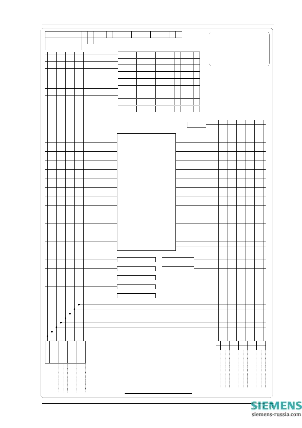
Relay Identifier
Relay Address
Settings Group No.
Alarm 1
Alarm 2
Alarm 3
Alarm 4
Alarm 5
Alarm 6
Alarm 7
Alarm 8
Alarm 9
Relay Healthy
7SG11 Argus 8 Appendix
Note:
This programming matrix can be
used for both E4 and E6 case
size ARGUS 8 variants. For
different I/O options and particular
relay configurations ignore the
redundant features.
VE1 Inhibit
VE2 Inhibit
VE3 Inhibit
VE4 Inhibit
3VoE1 Inhibit
3VoE2 Inhibit
V2E1 Inhibit
V2E2 Inhibit
FE1 Inhibit
FE2 Inhibit
FE3 Inhibit
FE4 Inhibit
PROTECTION FUNCTIONS
Settings Group Select
Clock Sync.
Waveform Trig
V Block Alarm
VE1 Starter
VE1 Trip
VE2 Starter
VE2 Trip
VE3 Starter
VE3 Trip
VE4 Starter
VE4 Trip
3VoE1 Starter
3VoE1 Trip
3VoE2 Starter
3VoE2 Trip
V2E1 Starter
V2E1 Trip
V2E2 Starter
V2E2 Trip
FE1 Starter
FE1 Trip
FE2 Starter
FE2 Trip
FE3 Starter
FE3 Trip
FE4 Starter
FE4 Trip
Trip Counter Alarm
PowerOn Count
Reset Outputs
Trip Circuit Fail
DO TIMER
PU TIMER
INVERTED INPUTS
LATCHED / HAND RESET
2 4 5 6 7
13
8 9 1011
123456789
Output Relays
Status Inputs
ARGUS 8 - Programming Matrix
©2011 Siemens Protection Devices Limited Chapter 9 Page 9 of 13
Page 93

7SG11 Argus 8 Appendix
Notes Pages
©2011 Siemens Protection Devices Limited Chapter 9 Page 10 of 13
Page 94
7SG11 Argus 8 Appendix
Notes Pages
©2011 Siemens Protection Devices Limited Chapter 9 Page 11 of 13
Page 95

7SG11 Argus 8 Appendix
Notes Pages
©2011 Siemens Protection Devices Limited Chapter 9 Page 12 of 13
Page 96

7SG11 Argus 8 Appendix
Notes Pages
©2011 Siemens Protection Devices Limited Chapter 9 Page 13 of 13
Page 97

Published by and copyright © 2010:
Siemens AG
Energy Sector
Freyeslebenstrasse 1
91058 Erlangen, Germany
Siemens Protection Devices Limited
P.O. Box 8
North Farm Road
Hebburn
Tyne & Wear
NE31 1TZ
United Kingdom
Phone: +44 (0)191 401 7901
Fax: +44 (0)191 401 5575
www.siemens.com/energy
For more information, please contact our
Customer Support Center.
Phone: +49 180/524 70 00
Fax: +49 180/524 24 71(Charges depending on provider)
E-mail: [email protected]
Power Distribution Division Order No. C53000-G7076-C3-2
Printed in Fürth
Printed on elementary chlorine-free bleached paper.
All rights reserved.
Trademarks mentioned in this document are the property of Siemens AG, its affili-
ates, or their respective owners.
Subject to change without prior notice.
The information in this document contains general
descriptions of the technical options available, which
may not apply in all cases. The required technical
options should therefore be specified in the contract.
www. siemens.com/energy
Siemens Protection Devices Limited 2
 Loading...